

Page 1
CRS1
ORDER NO. MD0509368C0
A6
Mechanism Unit
CONTENTS
Page Page
1 Mechanism Overview 3
2 Mechanism Drive Unit
2.1. Tray Open/Close and Multi-Discs Change operations
2.2. Disc Selection operation
2.3. Play/Stop operation
3 Mechanism Operation Description
3.1. General Feature
3.2. Hardware composition
3.3. Mechanism Operation
3.4. Switches Chattering Check
3.5. Motor Movement Control
3.6. Plunger Timing Chart
3.7. Initialization of Mechanism Unit.
3.8. Mechanism "HOME" position
3.9. Mechanism "Play Driving" position
3.10. Trays Operation
3.11. Drive tray between STOCK and PLAY position
3.12. Selection of Tray by Moving UD base Up/down
3.13. Fail Safe
3.14. Manual Trigger Tray Close
3.15. Changer Error Code
4 Self diagnosis and special mode setting
12
12
12
15
16
17
18
25
26
29
30
31
32
4
4
5
7
9
9
9
9
4.1. Special Mode Table 32
4.2. Error code Table
5 Troubleshooting Explorer
5.1. Preparation of service jig
5.2. Checking of Changer Unit
5.3. Setting the trays in "STOCK" position
6 Flow Chart
6.1. Disassembly Flow Chart
6.2. Assembly Flow Chart
6.3. Disassembly Flow
7 Assembling and Disassemb ling Procedure.
7.1. Disassembling Procedures
7.2. Assembling Procedure
8 CRS1 (Changer Unit) Ageing / Reliability
8.1. Equipments
9 Notes of Schematic Diagram
10 Schematic Diagram
10.1. CD Loading Circuit
11 Printed Circuit Board
11.1. CD Loading P.C.B.
12 Exploded Views
12.1. CD Loading Mechanism
34
38
38
38
38
49
49
50
51
53
53
73
93
93
94
95
95
96
96
97
97
© 2005 Matsushita Electric Industrial Co. Ltd.. All
rights reserved. Unauthorized copying and
distribution is a violation of law.
Page 2

CRS1
13 Replacement Parts List 100
13.1. CD Loading Mechanism Parts List
101
13.2. Electrical Parts List
102
2
Page 3
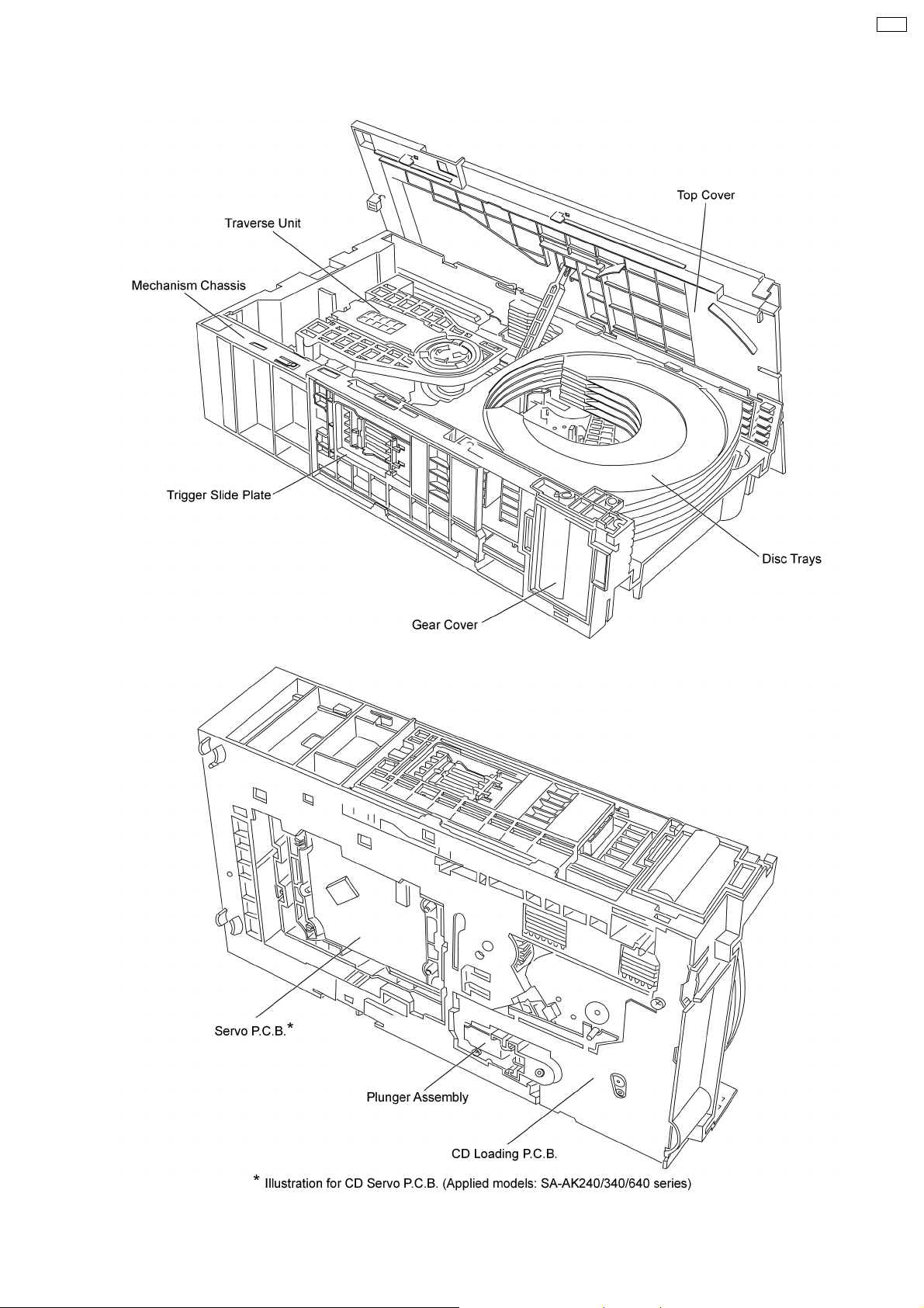
1 Mechanism Overview
CRS1
3
Page 4
CRS1
2 Mechanism Drive Unit
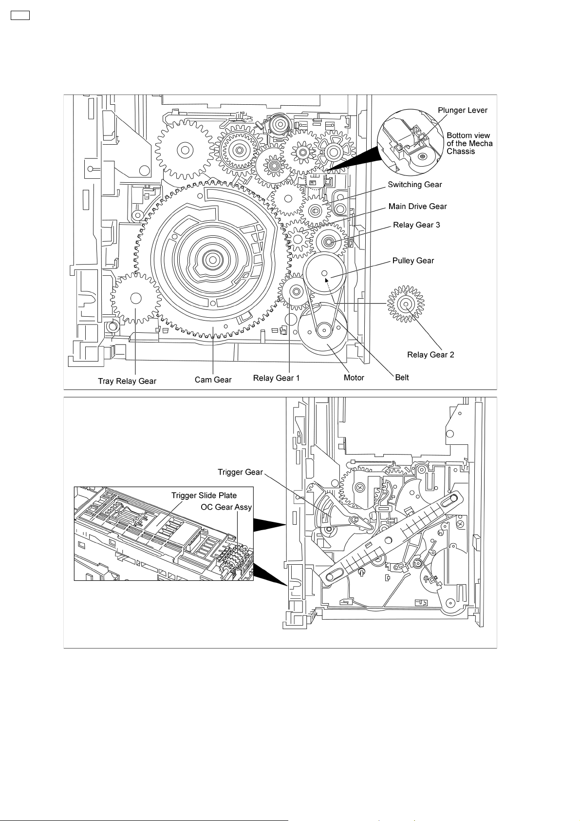
2.1. Tray Open/Close and Multi-Discs Change operations
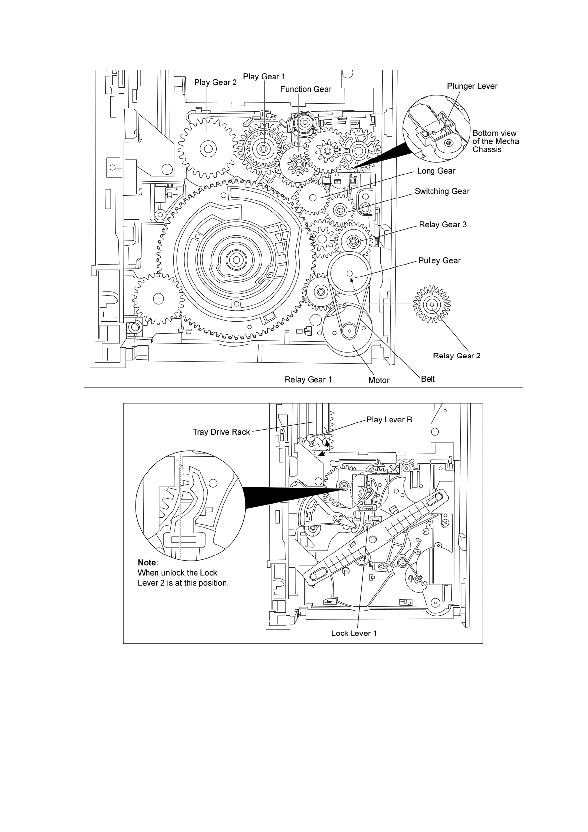
2.1.1. Description of tray open/close and multi-discs change operations
1. The motor turns in the clockwise direction and the rotation is transmitted via the belt, the pulley gear also turns clockwise.
2. The relay gear 1 turns counterclockwise.
3. The relay gear 2 turns clockwise.
4. The relay gear 3 turns counterclockwise.
5. The switching gear at down position turns clockwise (up/down position functioned by the plunger lever).
6. The main drive gear turns counterclockwise.
4
Page 5
7. The cam gear turns clockwise, which is engaged with the trigger gear and slide plate, are driven, causes the tray lock lever
unlock.
8. The tray relay gear turns counterclockwise, which is engaged with the OC assy, is driven.
9. The movement of the OC assy releases the disc trays.
(The operation of the disc trays closed is the opposite of that for opening of disc trays.)
2.2. Disc Selection operation
CRS1
5
Page 6

CRS1
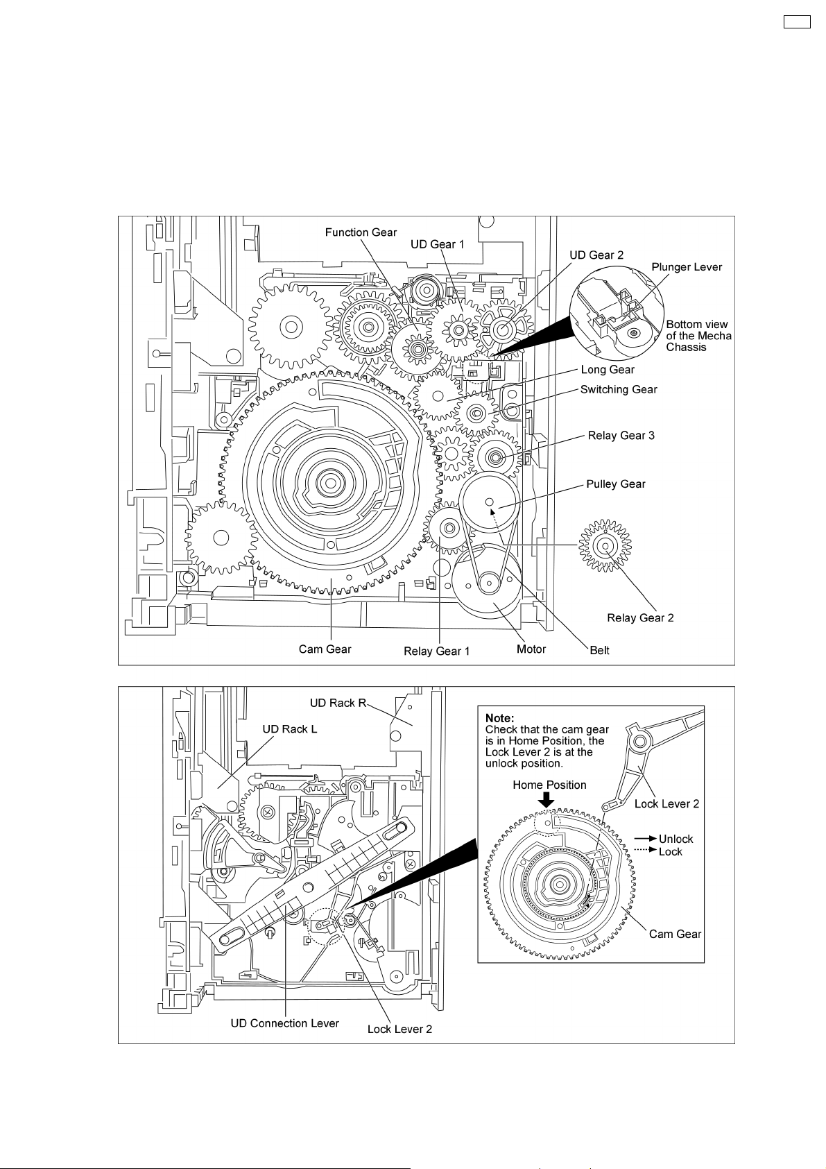
2.2.1. Description of disc selection operation
Note: Check that the cam gear is in “HOME” position.
1. The motor turns in the clockwise direction and the rotation is transmitted via the belt, the pulley gear also turns clockwise.
2. The relay gear 1 turns counterclockwise.
3. The relay gear 2 turns clockwise.
4. The relay gear 3 turns counterclockwise..
5. The switching gear move up turns clockwise (up/down position functioned by the plunger lever).
6. The long gear turns counterclockwise.
7. The function gear moved up turns clockwise.
8. The UD gear 1 turns counterclockwise.
9. The UD gear 2 turns clockwise engaged with the UD rack R drives the UD connection lever turns clockwise, UD rack L, is driven
to move the traverse deck assembly up.
(The operation of the traverse deck assembly down is the opposite of that for the traverse deck assembly up.)
6
Page 7
2.3. Play/Stop operation
CRS1
2.3.1. Description of play/stop operation
Note: Check that the Lock Lever 1 is unlock.
1. The motor turns in the clockwise direction and the rotation is transmitted via the belt, the pulley gear also turns clockwise.
2. The relay gear 1 turns counterclockwise.
3. The relay gear 2 turns clockwise.
4. The relay gear 3 turns counterclockwise.
5. The switching gear move up turns clockwise (up/down position functioned by the plunger lever).
6. The long gear turns counterclockwise.
7
Page 8

CRS1
7. The function gear move down turns clockwise.
8. The play gear 1 turns counterclockwise.
9. The play gear 2 turns clockwise engaged with the tray drive rack and tray catch lever to push in the disc trays.
10. Play lever B engaged with the traverse deck assembly’s play lever A, causes slide plate move towards to the play position.
8
Page 9
3 Mechanism Operation Description
3.1. General Feature
· This is a five disc changer mechanism for CD/DVD. The outline figure is shown below.
CRS1
· The mechanism has "CHANGE WHILE PLAY" function. It open other trays for disc exchanging while one tray is at PLAY
position performing recording or reproducing.
· The mechanism can quickly change all trays with "CHANGE ALL" function. All trays can be move to OPEN position with one
operation.
· There is no sensor to indicate presence of disc on any tray.
3.2. Hardware composition
· Below is the hardware components of the mechanism
Name Function
Open Switch (OPEN-SW) The switch is used to detect normal tray opening
The switch is used for detect tray being manually push/trigger when full open
Home Switch (HOME-SW) Is used to detect cam gear home position
Close Sensor (CLOSE-SENSOR) Used for normal single tray closing
Used to detect cam gear rotate to Play Driving position
Play Switch (PLAY-SW) Detect TRV clamping complete position
Stocking Switch (STOCK-SW) Detect tray completely transfer for play position to stocking positi
UD Sensor (UD-SENSOR) Detect TRV vertical movement position
Top Switch (TOP-SW) Detect a default position of TRV vertical movement position
Driver IC To drive Motor
Motor Main driving source for changer
Plunger Switching the driving source from motor to:
1. Tray open/close
2. Drive tray to play/stock position and TRV vertical movemen
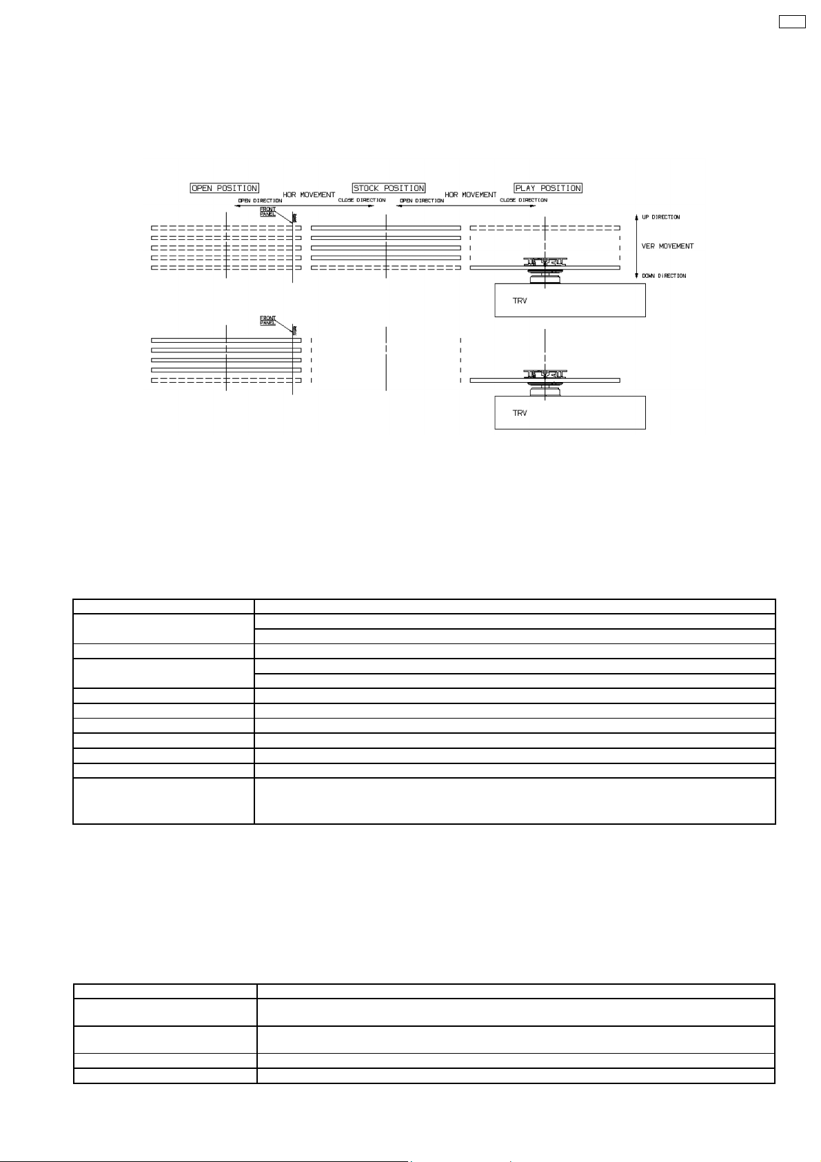
3.3. Mechanism Operation
· This mechanism has the following state:
1. Driving of a tray to open/close
2. Up/down operation of a traverse performs a state changes of tray.
By using the plunger to lift/release of a switching gear, and the cam gear to lift/release the function gear the motor can be link
to several gear trains to perform various operations.
· The functions that can be perform in this mechanism are described as below:
Condition Explanation
Open current playing tray The state to change current playing disc. All tray will be open at once and current tray at PLAY position
Open All The state where all trays being driven to OPEN position. The disc can be taken in or out from tray to tray
Stock The state where the trays are stored in STOCK position
Play The state where one of the tray 5 trays is being driven to PLAY position and clamped by traverse unit
will be expose.
by close tray one by one from top to bottom.
9
Page 10
CRS1
Condition Explanation
Play & Open Tray-* The state where one of the tray is in playing position performing recording or reproducing, other trays can
Change The state when one of the opened tray being driven from OPEN position to STOCK position and other
Close All The state where all open trays will being driven from OPEN position to STOCK position, one by one from
Note: * represent tray number (from 1 ~ 5)
be used (OPEN position) for disc exchanging without stopping the recording or reproducing process.
opened trays remain still at OPEN position.
top to bottom
· Logics of motor control:
Action CW CCW Plunger
Tray Opening H L L
Tray Closing L H L
Cam move from Home Position to Play Driving Position H L L
Cam move from Play Driving Position to Home Position L H L
Drive tray to PLAY position H L H
Drive tray to STOCK position L H H
UD base moving upward H L H
UD base moving downward L H H
Notes :
CW/CCW : Motor direction control (CW : clockwise, CCW : Anti-clockwise)
Plunger : Solenoid Control (H : ON = Activation)
· Cam gear in the mechanism use for opening/closing of trays and lifting a function gear to link to gear train that drive UD base
moving up/down. When cam gear is being driven to play driving position, the function gear will be bring down to link the gear
train that drive tray to and from STOCK position and PLAY position. Below are the relation between mechanism function and
cam gear movement and position
Motor Direction Plunger Unit Cam gear movement/position Function
CW Release Home SW → rotate CW Trays Open
CCW Release Rotate CCW → Home SW Trays Close
CW Release Home SW → close sensor 1st L-H signal Cam gear move from Home Position to Play
CCW Release Close sensor 1st (H → L) signal → Home SW Cam gear move from Play Driving Position to
CW Up Cam Stop at Home Position UD base moving from bottom to top
CCW Up Cam Stop at Home Position UD base moving from top to bottom
CW Up Cam Stop at Play Driving Position Tray move from STOCK to PLAY position
CCW Up Cam Stop at Play Driving Position Tray move from PLAY position to STOCK
Driving Posi
Home Position
Position
· Cam gear rotation direction, switch and state changes is show in figure below:
· The movement of UD base (vertical up/down) and driving of tray(s) between STOCK position and PLAY position is only enable
when plunger ON (lift up the switching gear to link driving source to the both gear train). Only one gear train can be driven at
one time, the selection of either gear train is depending on cam gear position. Below are figure showing the operation of motor
driving direction and its function carry out.
Cam Gear
Motor Home Position (UD Driving Position) Play Driving Position
CW UD base move upwards direction 5→1 Stock → Play
CCW UD base move downwards direction 1→5 Play → Stock
· For driving UD base up/down the cam gear must be at the home position (UD driving position) and plunger need to be
activated, the switch and state change is as figure below:
10
Page 11
· To drive the tray(s) between STOCK/PLAY position, cam gear must be at the play driving position and plunger need to be
activated, the switch and state change is as figure below:
CRS1
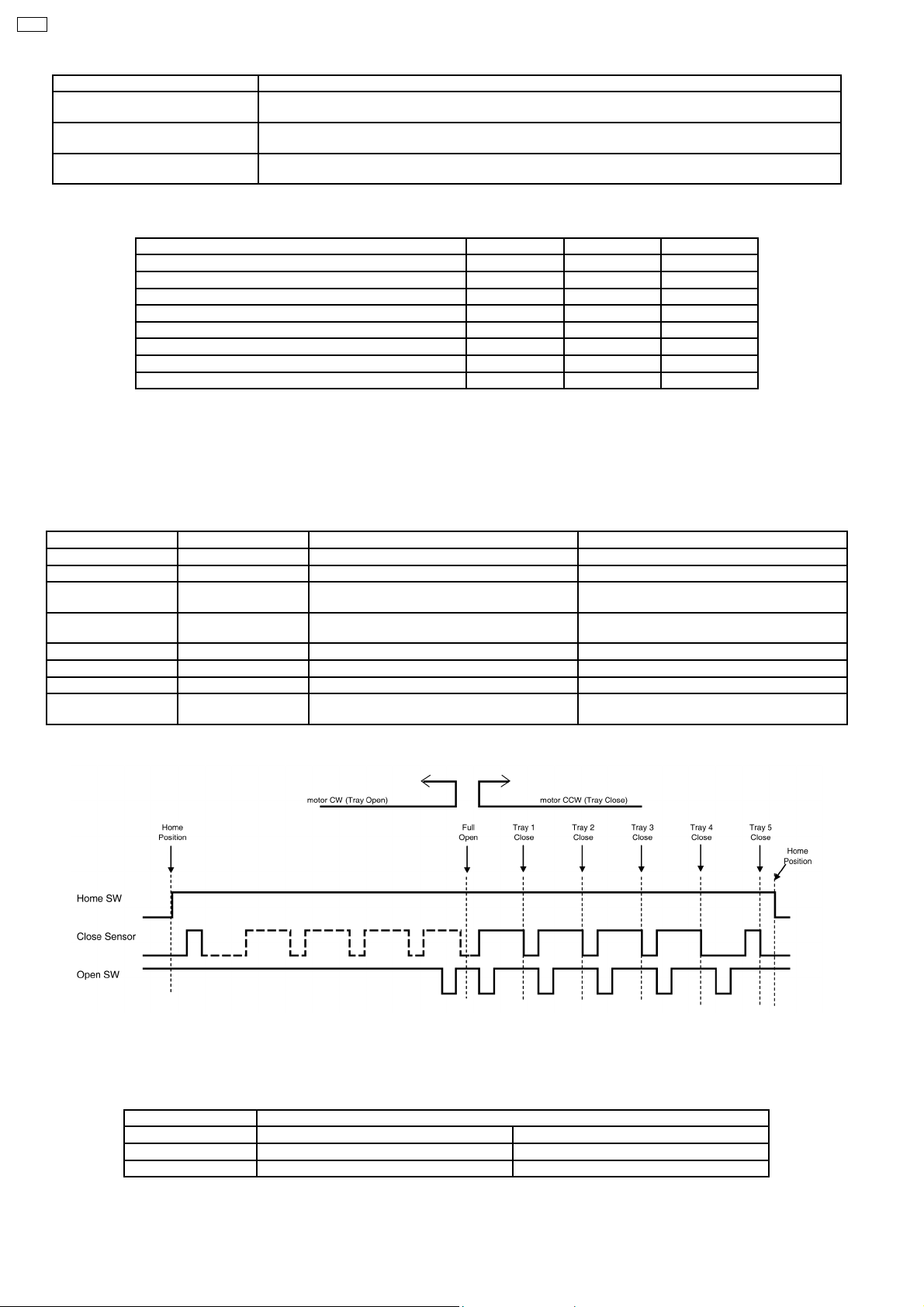
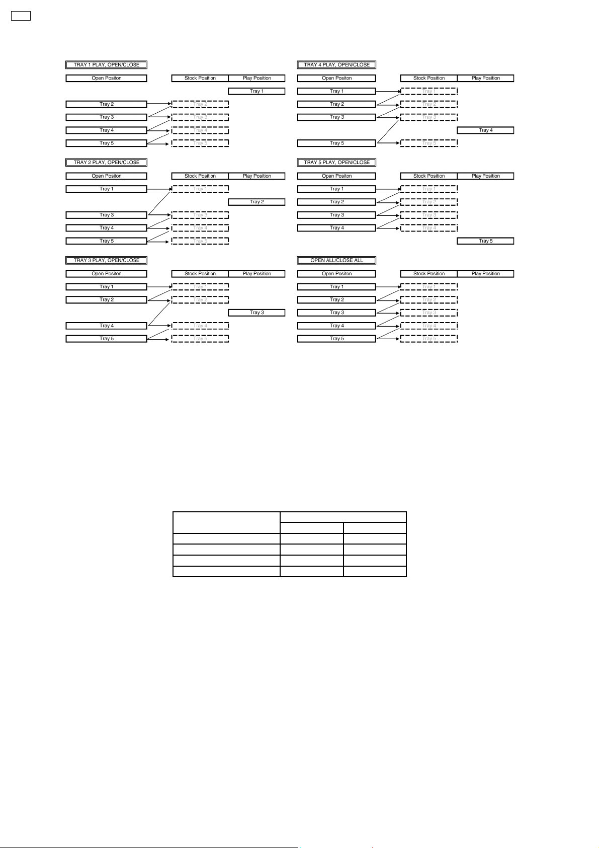
· The mechanism tray opening and closing is cycle process. It is able to open all trays in STOCK position while one of the tray
is in PLAY position. The closing can be done one by one or close all at once depend on the user instruction. Below show the
tray opening and closing flow.
11
Page 12
CRS1
3.4. Switches Chattering Check
· Each input shall perform chattering check processing.
OPEN-SW 2ms Periodic sampling. It logic-decides by continuation same 5 times.
PLAY-SW 2ms Periodic sampling. It logic-decides by continuation same 5 times.
STOCK-SW 2ms Periodic sampling. It logic-decides by continuation same 5 times.
TOP-SW 2ms Periodic sampling. It logic-decides by continuation same 5 times.
HOME-SW 2ms Periodic sampling. It logic-decides by continuation same 5 times.
UD-SENSOR 2ms Periodic sampling. It logic-decides by continuation same 5 times.
CLOSE-SENSOR 2ms Periodic sampling. It logic-decides by continuation same 5 times.
3.5. Motor Movement Control
Condition Motor
CW CCW
Free L L
Rotate CW H L
Rotate CCW L H
Short Brake H H
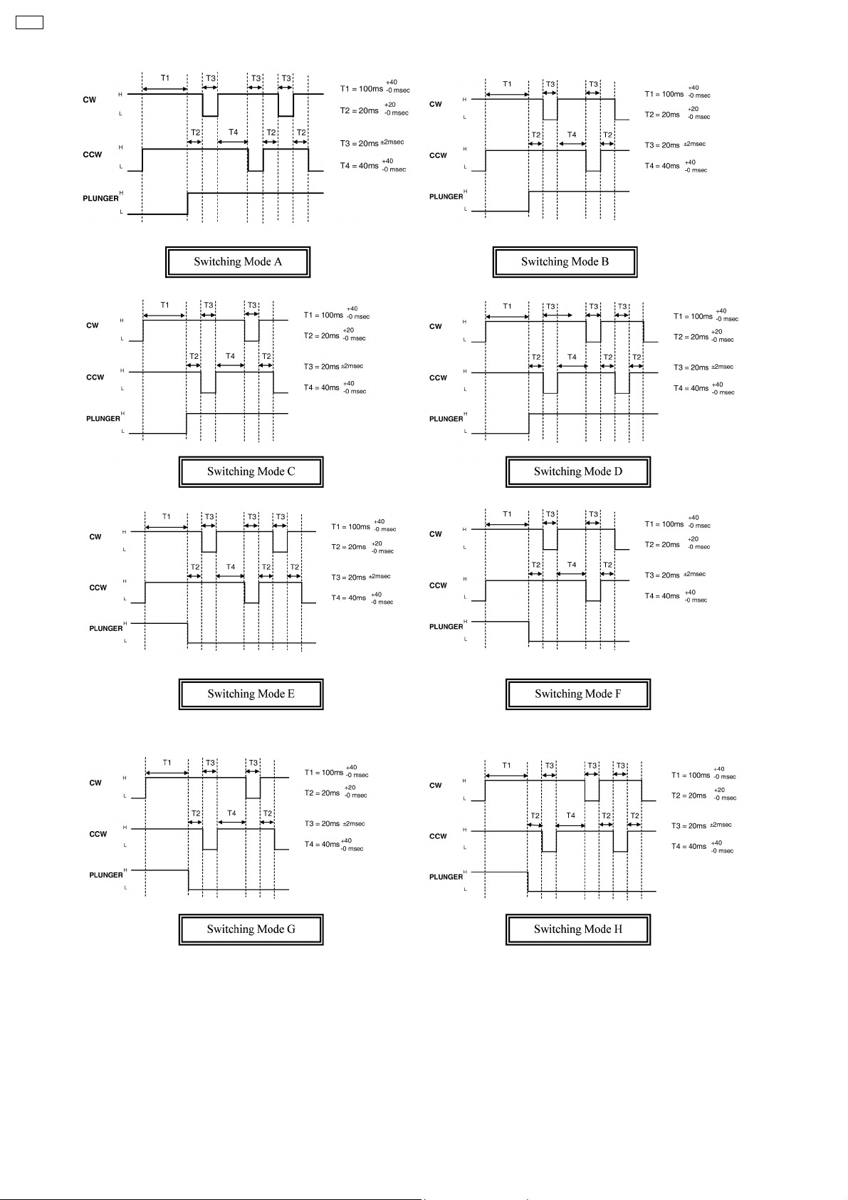
3.6. Plunger Timing Chart
· Plunger is use for pulling the lever that a switching gear is sit on the lever. When current supply to the plunger to pulling (kick)
switching gear, it will be lift up to engage to 1
be bring done by gravity force and mechanical coil spring on top of it. Plunger use for connect the driving source from motor
to 2 different gear train in the mechanism, the functions of the gear trains are as below:
1. Tray open/close
2. Drive tray to play/stock position and TRV vertical movement
st
gear train. When current supply to plunger is cut off (release), switching gear will
· The plunger movement is define as below:
Kick = H, Release= L
· Each time during plunger activation time (Kick/Release), the motor shall perform a short time CW and CCW rotation for release
the gear side force and ensure complete gear to gear engagement.
12
Page 13
· The basic concept of the motor rotation sequence (CW or CCW) is base on the initial and final motor rotating direction. The
direction should be opposite to the initial and final motor driving direction in order to:
1. To release the gear teeth side force
2. To release mechanism belt tension
3. To ensure switching gear disengage or engage into other gear´s teeth
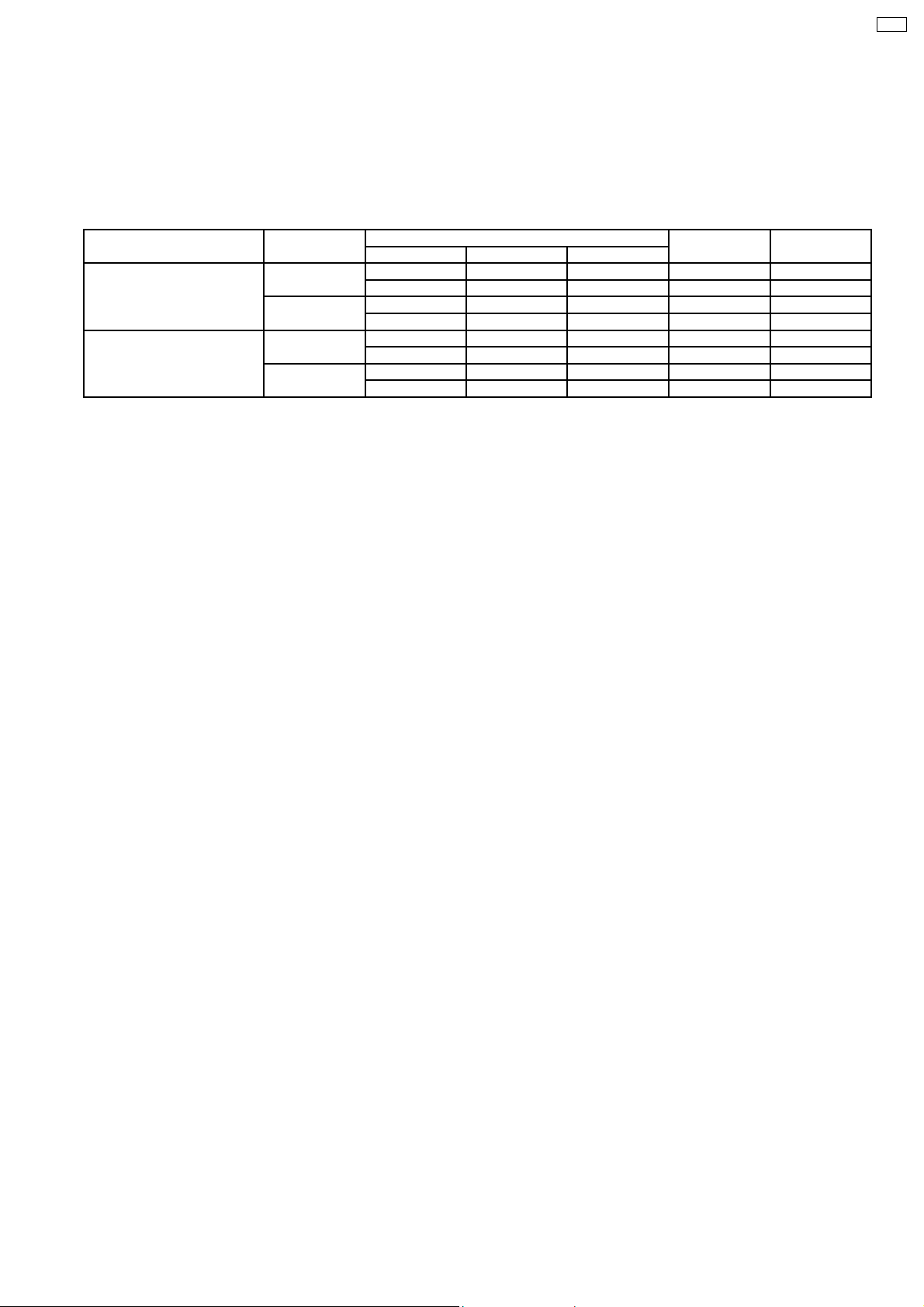
· Summary of the type of motor short rotation direction is as below:
Motor Direction Initial Short Rotate Direction Final Switching Mode
Plunger Kick CW CCW CW CCW CW A
CCW CW CCW - CW C
Plunger Release CW CCW CW CCW CW E
CCW CW CCW - CW G
st
1
nd
2
rd
3
CCW CW - CCW B
CW CCW CW CCW D
CCW CW - CCW F
CW CCW CW CCW H
· Below are the timing charts of plunger activation time.
CRS1
13
Page 14
CRS1
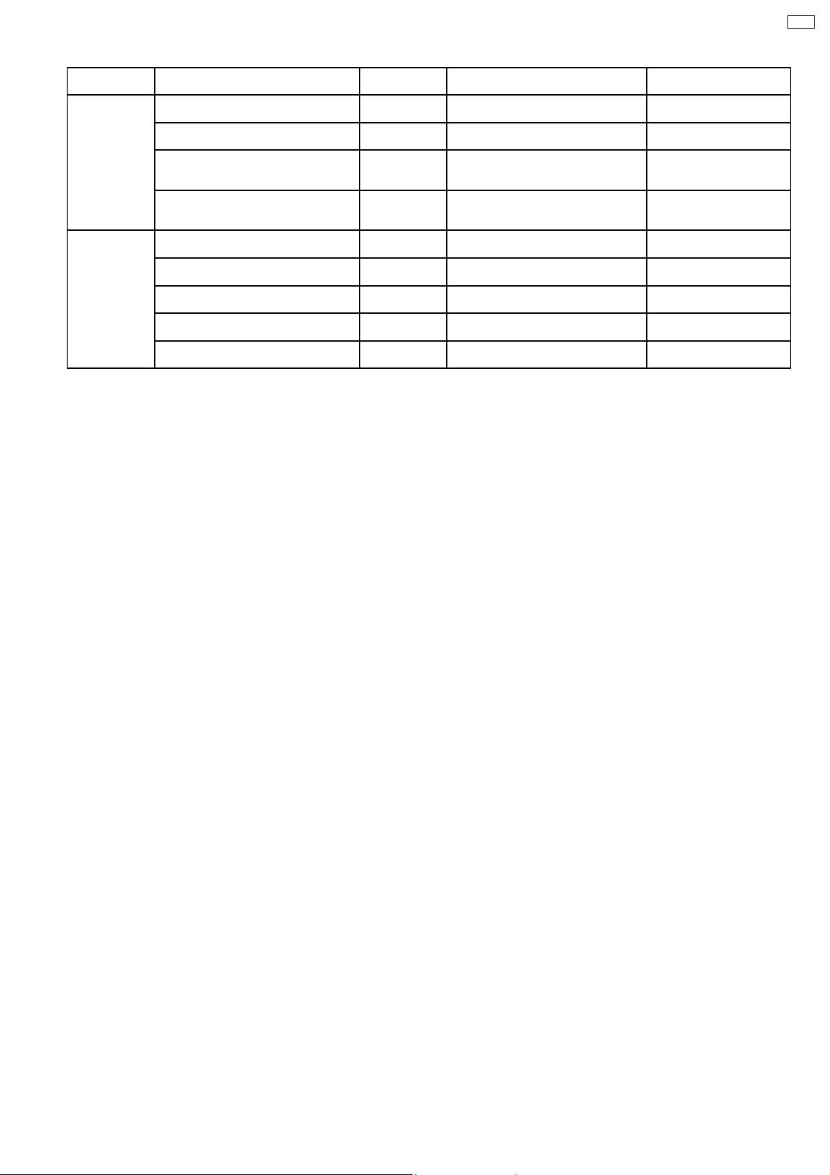
· As the plunger only activate at 2 position of cam gear. The plunger mode summary as below:
14
Page 15
CRS1
Switching
Position
Home
Position
Play
Driving
Position
Cam gear rotate CCW to HOME
Motor : CCW
Cam gear rotate CCW to HOME
Motor : CCW
UD base move from bottom to top
Motor : CW
UD base move from top to bottom
Motor : CCW
Cam gear rotate CW from HOME to Play
Driving Position. Motor : CW
Cam gear rotate CW from HOME to Play
Driving Position. Motor : CW
Drive tray from STOCK position to PLAY
position. Motor : CW
Drive tray from PLAY position to STOCK
position. Motor : CCW
Drive tray from PLAY position to STOCK
position. Motor : CCW
Initial Motor Direction Switching
Mode
C UD base move from bottom to top
D UD base move from top to bottom
E Cam gear rotate CW from HOME to
G Cam gear rotate CW from HOME to
A Drive tray from STOCK position to
B Drive tray from PLAY position to
F Cam gear rotate CCW from Play
H Cam gear rotate CCW from Play
G Cam gear rotate CW from until trays full
Initial Motor Direction Function
Motor : CW
Motor : CCW
Play Driving Position. Motor : CW
Play Driving Position. Motor : CW
PLAY position. Motor : CW
STOCK position. Motor : CCW
Driving Position to HOME. Motor : CCW
Driving Position to HOME. Motor : CCW
open. Motor : CW
Tray selection from bottom
to top
Tray selection from top to
bottom
After tray selection, cam
gear rotate to Play Driving
Position
After tray selection, cam
gear rotate to Play Driving
Position
Load tray to Play
Unload tray from Play to
Stock
After load tray to Play, cam
gear return to HOME
After unload tray from Play,
cam gear return to HOME
Open trays while one tray
Play
· Switching mode G is used during initialization to ensure that the switching gear is at the release (down) condition before the
initialization process begins.
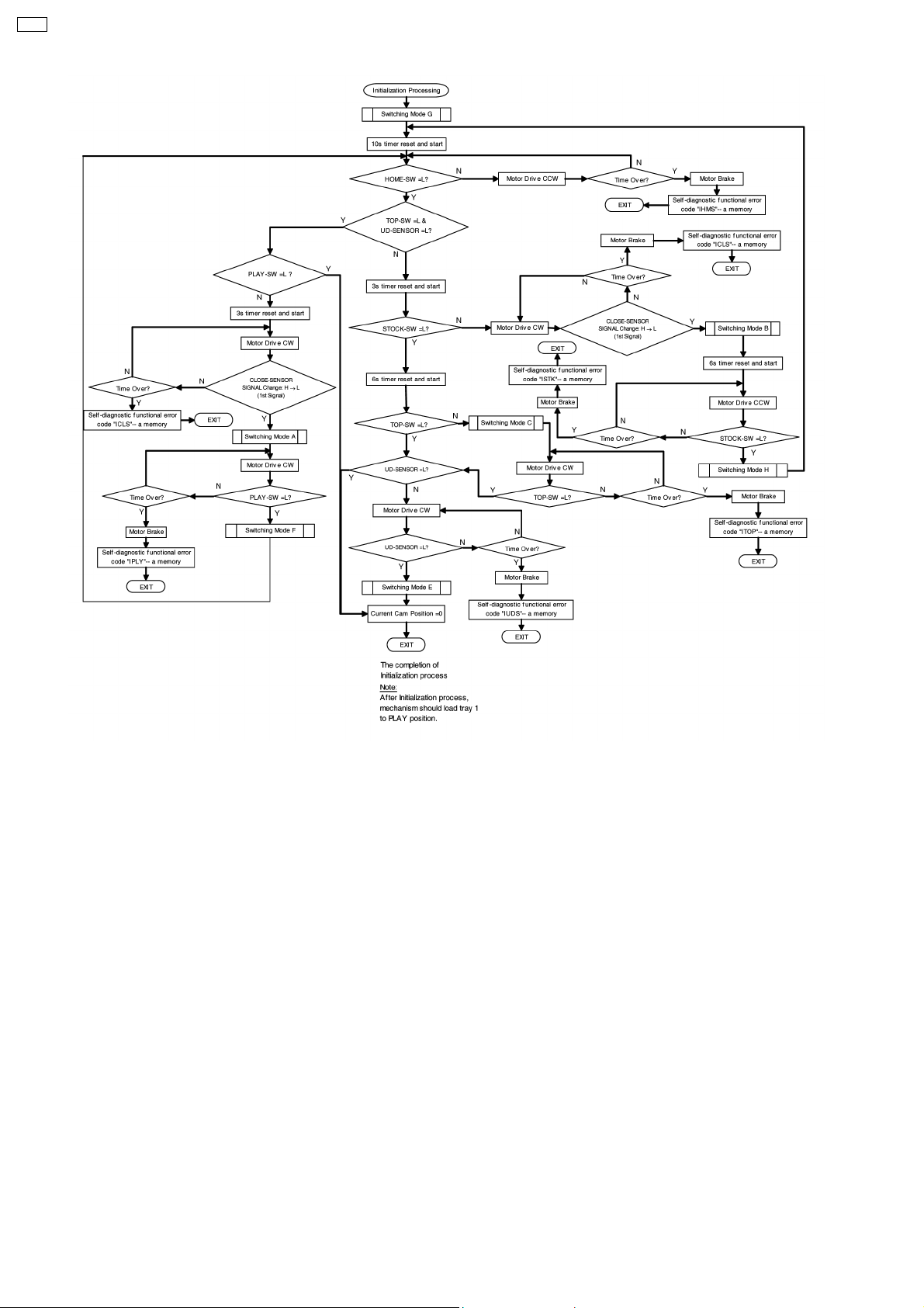
3.7. Initialization of Mechanism Unit.
· Mechanism Initialization -- This mechanism is designed to operate & set to a pre-defined position to prevent malfunction when
unavoidable circumstances happen. For examples: user mis-handling during transportaion or abnormal user operations.This is
comply to the product shippin g reliability standards.
· Mechani sm is initialized when the mechanism controller is unable to detect the present condition/state of mechanism. For
example, when the microcomputer carries out a cold start. (In complete unit)
· Once the initialization process is completed, the mechanism unit is set to this condition:-
1. Tray 1 is at PLAY position (Top tray)
2. The traverse unit is at clamping condition (PLAY SW-L)
3. All the remaining trays are in STOCK Position (Trays 2 ~ 5 )
4. Plunger lever at release condition
5. Cam gear is at Home position ( HOME SW-L)
6. Motor is free (CW-L, CCW-L)
Note: This is same as shipment condition. (In complete unit)
· Below is the flow chart of the initialization process:-
15
Page 16
CRS1
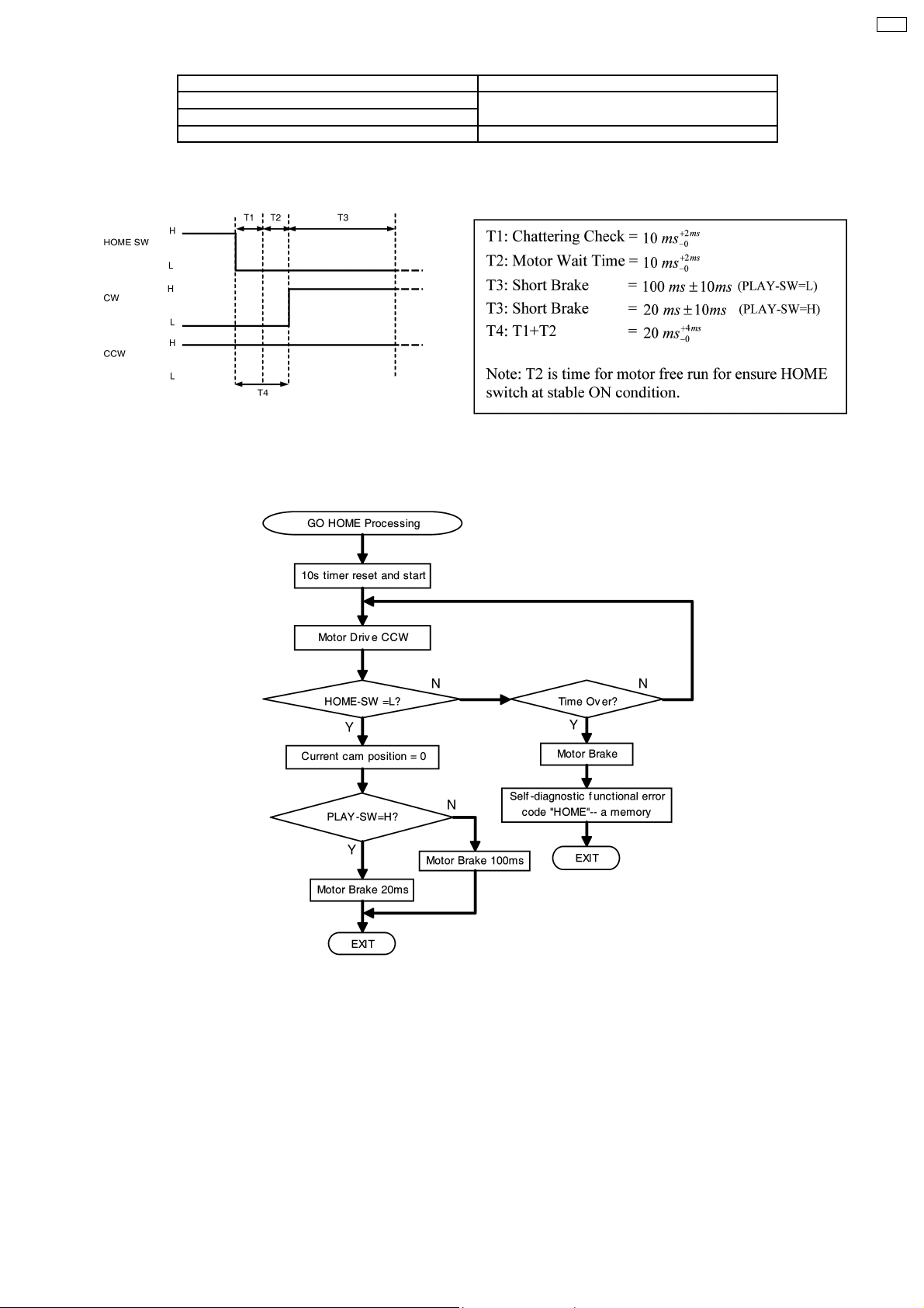
3.8. Mechanism "HOME" position
· Mechanism HOME position is a starting position for few functions, such as below:
1. Load tray from STOCK position to PLAY position
2. Unload tray from PLAY position to STOCK position
3. Open trays
4. Driving UD base up/down
· Besides this, it will always return to “HOME” position after performing below functions:
1. After tray completely clamped by Traverse unit
2. Closing All trays
3. Closing tray 5
4. After completely the UD base movement
· There are 2 type of mode to go to HOME position.
Mode 1 is to go to HOME position and motor brake and stay at HOME position, motor need longer brake time for reduce overrun
of mechanical parts.
For Mode 2, after mechanism go to HOME position, motor immediately rotate reverse direction to go do loading/unloading
processing, shorter brake time necessary to reduce the total mechanism operation time.
The table below is types of "GO HOME" mode and operation that use it.
16
Page 17
GO HOME MODE 1 GO HOME MODE 2
1. After loading tray to PLAY position 1. After closing all trays (no tray at PLAY position)
2. After unloading tray to STOCK position
3. After closing all trays (one tray at PLAY position)
· The timing chart for the mechanism to set to “HOME” position is illustrated as below.
CRS1
· Below is the flow chart for the mechanism to set to “HOME” position.
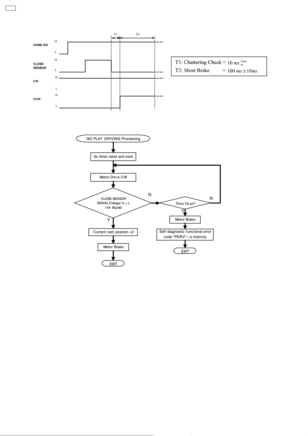
3.9. Mechanism "Play Driving" position
· Play driving position is a position driving source linkage to drive the tray(s) between STOCK position and PLAY position (load
and unload of tray). Cam gear will rotate to this position from HOME position, and after the completion of clamping process will
back to HOME position.
For Go to Play Driving position, cam gear move from HOME position, motor brake after detect 1
change from H→L
17
st
time CLOSE sensor signal
Page 18
CRS1
· Below is the flow chart for the mechanism to set PLAY DRIVING position.
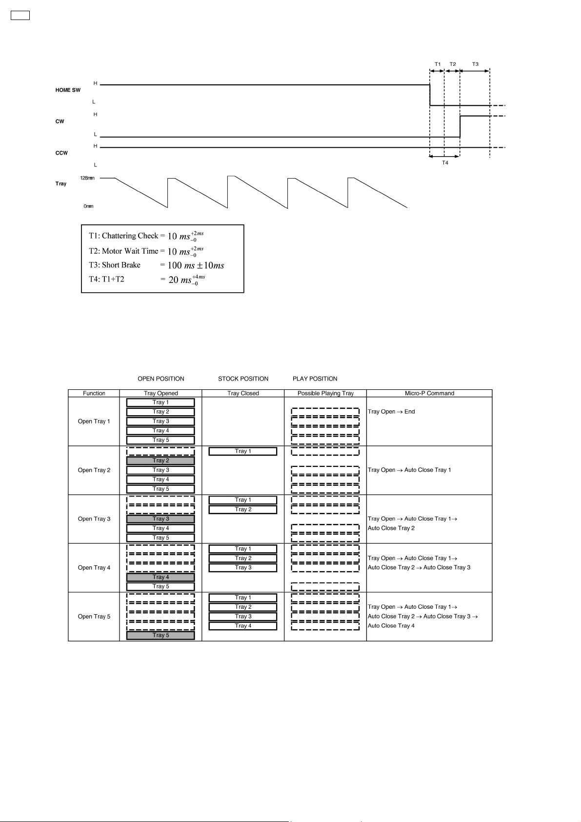
3.10. Trays Operation
3.10.1. Tray ‘Open’ Operation
· Changer mechanisms are required to open trays to load a disc. This mechanism feature s an "All Open" or "Change all one by
one" function for quick & easy disc change. There are 3 kinds of "Tray Open" conditions.
1. All trays open
Occurs when OPEN/CLOSE button is pressed, playing tray will be driven to STOCK position and all trays will driven to
OPEN position. All trays will remain open until "DISC CHANGE" or "OPEN/CLOSE" is pressed. When "DISC CHANGE" is
pressed, the upper most tray will close while "OPEN/CLOSE" is close all trays.
2. Open selected tray while one tray at PLAY position
Occurs when specify tray is selected to be opened while one tray is at PLAY position. This operation never disturbs the
playing disc operation and allow user to change desire disc on specific tray.
3. Direct open playing tray
Occurs only when the user selects to open playing tray. Tray at PLAY position will stop recording/reproducing process and
being driven to STOCK position. This will follow by driven all trays to OPEN position and trays closing until the previous
playing tray expose for disc changing.Example: User press "DISC CHANGE" + "DISC 3". Mechanism opens all the trays,
then closes trays 1 & 2 respectively exposing the tray 3.
18
Page 19

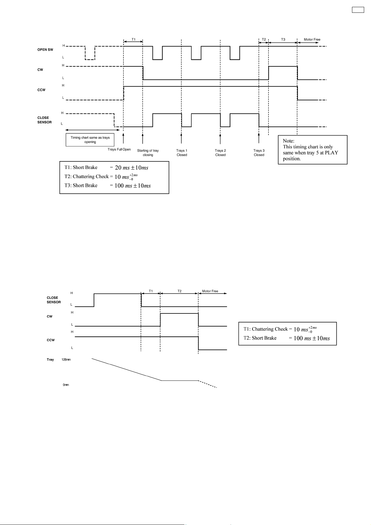
· The timing chart for both positions is the same, motor rotate CW direction, until OPEN SW changing signal H→ L → H, motor
need to continue run for 45ms.
· Motor free at the end of tray open, this is for enable the tray to be manually pushing by user.
· Below is the timing chart for tray opening.
CRS1
· For all type of trays openin g, either 4 trays (open remaining) or 5 trays (all open) will be set to OPEN position.
3.10.2. Tray Closing Operation
· The following action is tray closing. For this mechanism, there are 3 types of trays closing also.
1. All trays close
When user press "OPEN/CLOSE" after trays open, all trays (at any condition) will being driven to STOCK position.
2. Auto Tray Close
This closing operation is an internal operation in the mechanism. This operation completes the open selected tray function.
Mechanism uses this operation to drive trays that cover top surface of desire tray to STOCK position and then expose the
selected tray for user to do disc exchanging.
3. Change
When user press "CHANGE", one tray will be driven to STOCK position. This operation is for changing disc one by one from
top to bottom. The operation each time will only drive the upper most tray to STOCK position, it can be only being interrupt
by "OPEN/CLOSE". If the "CHANGE" being pressed during one tray is closing, mechanism will close the second tray
immediately after 1
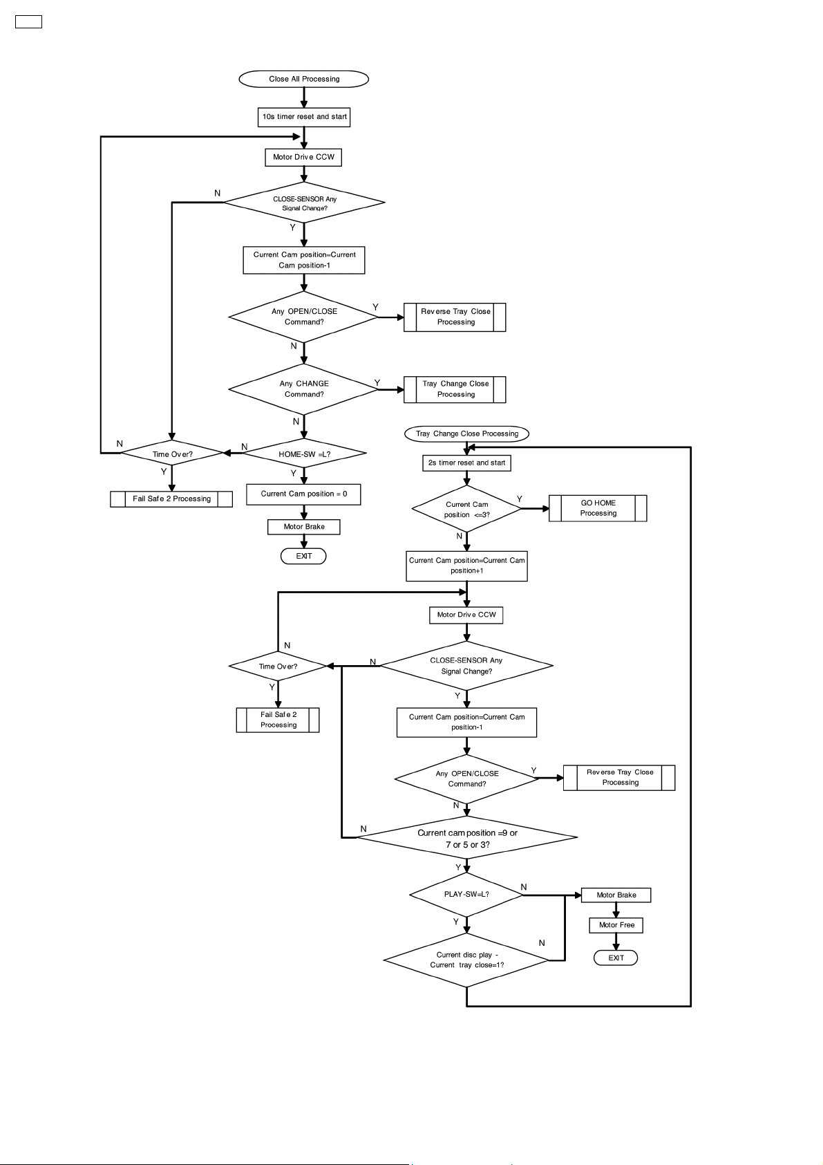
· All trays close can occurs anytime when there is tray at open condition. The all trays close processing is used when mechanism
carry out the function as:
1. Close Tray 5
2. Close Tray 4 while tray 5 is in PLAY position
3. User press OPEN/CLOSE to instruct all trays close.
st
tray. The number of tray will be closed equal to numbe r time of "CHANGE button " being pressed.
· Mechanism will close all the trays by rotating cam gear at CCW direction until detect HOME position
· Below is the timing chart for tray close (until detect HOME position).
19
Page 20
CRS1
· Table below explain the function of open selected tray while one tray at PLAY position. This table indicated the possible tray
at playing trays. For opened tray, all trays will be open except the tray at PLAY position. Trays will close to expose the selected
tray for user to input or change the disc.
· Timing chart below, shown an example of user select to open tray 4 only.
20
Page 21
CRS1
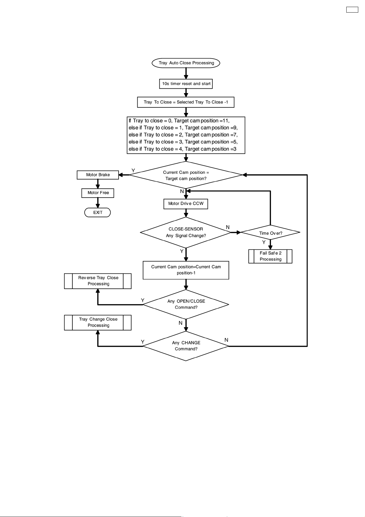
· The "Change" operation is to close one tray each time when "CHANGE" is pressed. This is the basic operation of "auto tray
close". The "change" operation will stop after detect a signal change in CLOSE-SENSOR while "auto tray close" count the
number of CLOSE-SENSOR signal change and stop at before selected tray start to move to STOCK position.
If there is a case where user select a upper level tray of current tray in PLAY position to be closed, (e.g. current tray at PLAY
position is tray 4, user select tray 3 to be open), micro-p counting of CLOSE sensor signal must done until tray 4 position, before
motor brake. The reason is to eliminate long waiting time for the next tray closing.
· Below is the timing chart of tray closing (Change Operation):-
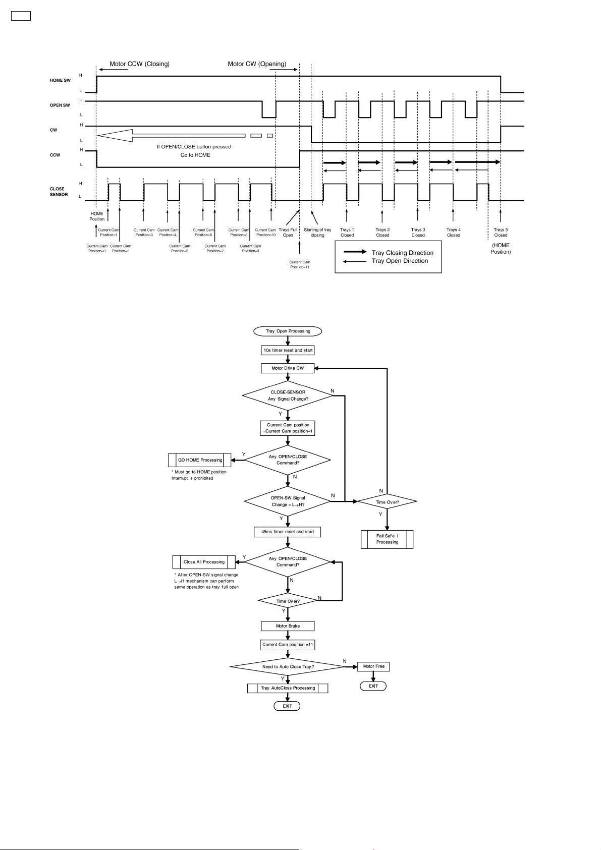
· Tray opening and closing is control by cam gear and CLOSE-SENSOR signal. OPEN-SW is only use for full open operation in
order to get more accurate tray stroke. Figure below show the cam gear rotation direction for tray opening and closing, and cam
important position.
21
Page 22
CRS1
· Below is the flow chart for tray open processing.
· The flow charts below shown the types of tray close processing, for tray auto close processing is use if user select a specify
tray to be close automatically after trays full open.
· Tray change close processing use if use select a function and want to change disc one by one from top tray to bottom tray.
22
Page 23
· Close all processing is use when user wants to close all trays at once, or want to close tray no.5 or close tray no.4 while tray
no. 5 is at PLAY position.
CRS1
23
Page 24
CRS1
· When there is a OPEN/CLOSE button pressed during tray open or tray close operation. Motor will rotate revere direction.
There are 2 type of cases, where 1
trays full open condition. For the 1
st
is before full open condition (open/close gear assembly still resting) and the 2ndis after
st
condition, motor will rotate the cam gear to move between HOME direction and tray open
24
Page 25

While for the 2ndcase, cam gear inside mechanism will move between specific positions by checking CLOSE-SENSOR signal
change.
· The flow chart for both open reverse (when tray opening motor reverse) and close reverse (when tray closing motor reverse)
is as below. The operation use when user press OPEN/CLOSE button during tray is opening or closing.
CRS1
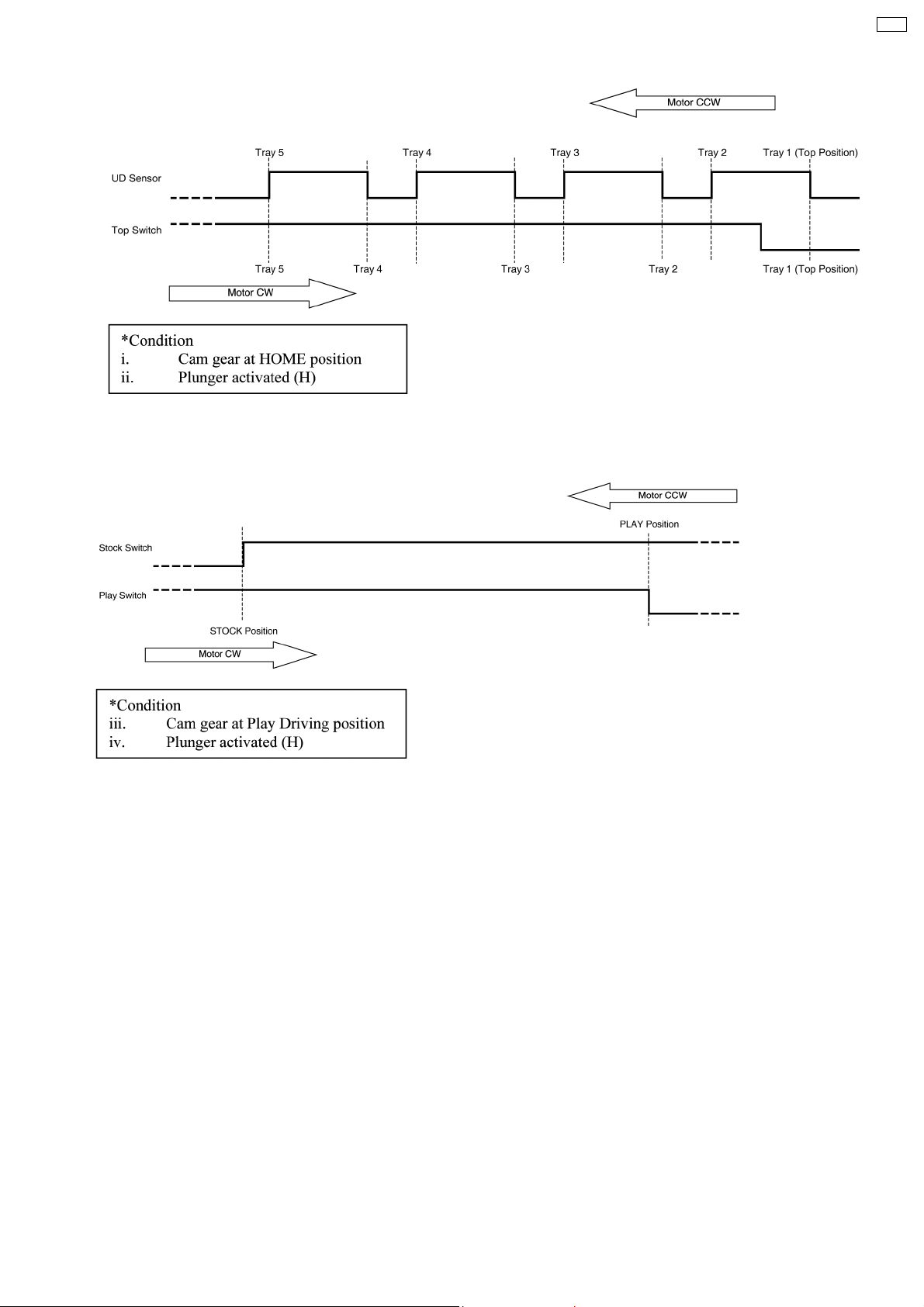
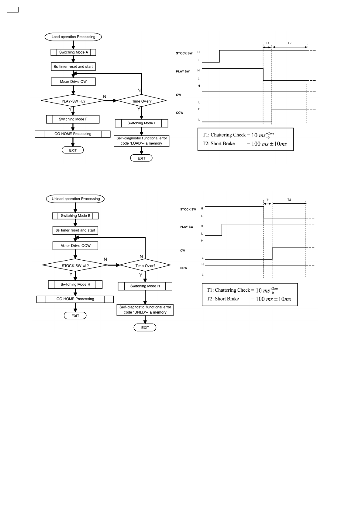
3.11. Drive tray between STOCK and PLAY position
· Play position is defined as the position whereas the tray is aligned to be played over the CD/ DVD unit. Only a single tray can
be at this location & note that the traverse mechanism is at its clamped position. Play position can be either disc playing (actively
reading disc data) or its not playing (no data reading).
* Shipment or Initialize positions always finish with a tray at this location.
· Loading operation is process to move tray from STOCK position to PLAY position.
· Unloadin g operation is process to move tray from PLAY position to STOCK position.
· If there is a certain operation key pressed at the middle of movement. The reversal operation is necessary. The reversal
operation should carry out after the tray arriving the STOCK position or PLAY position.
· The flow chart and timing chart for load a disc from STOCK position to PLAY position is as below:
25
Page 26
CRS1
· The flow chart and timing chart for unload a disc from PLAY position to STOCK position is as below:
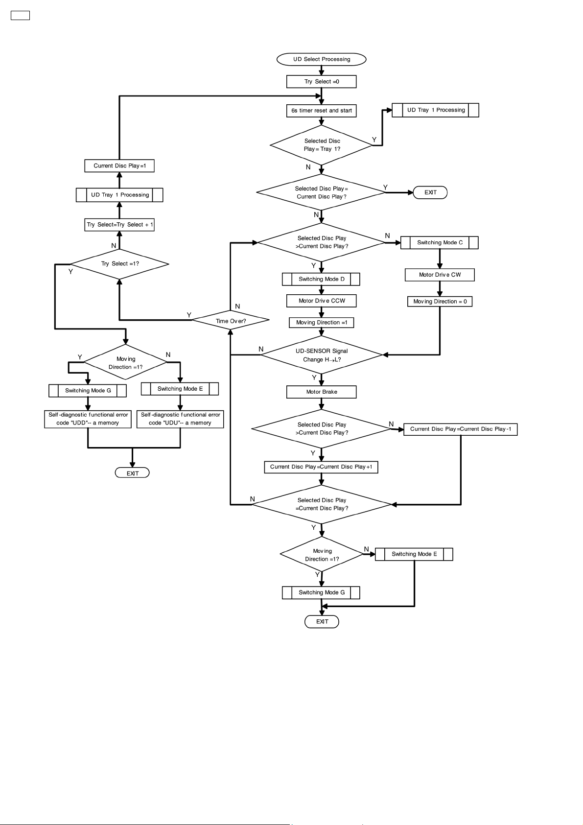
3.12. Selection of Tray by Moving UD base Up/down
· Tray alignment & selection is achieved by UD (up/down) movement, whereas the Mechanism vertically aligns itself to the
selected tray to be driven to PLAY position or STOCK position. The upper most tray is defined as tray 1 and bottom most tray
is defined as tray 5. Counting is achieved by resetting during initialization to the TOP-SW (tray 1) and counting the signal
change by UD-SENSOR.
· Below are the timing chart for UD base tray selection Up/down:
26
Page 27
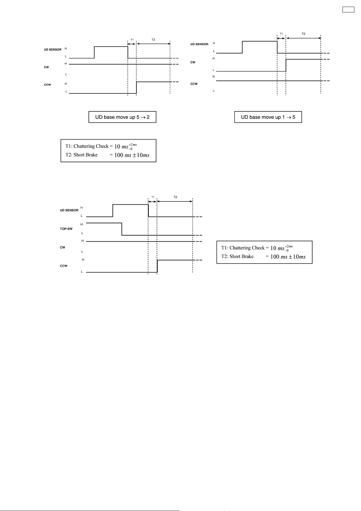
· Tray 1 is the reset position for UD base up/down processing. The position should be unique; a TOP-SW is use in this purpose.
CRS1
· Below is the flow chart for UD selection processing.
27
Page 28
CRS1
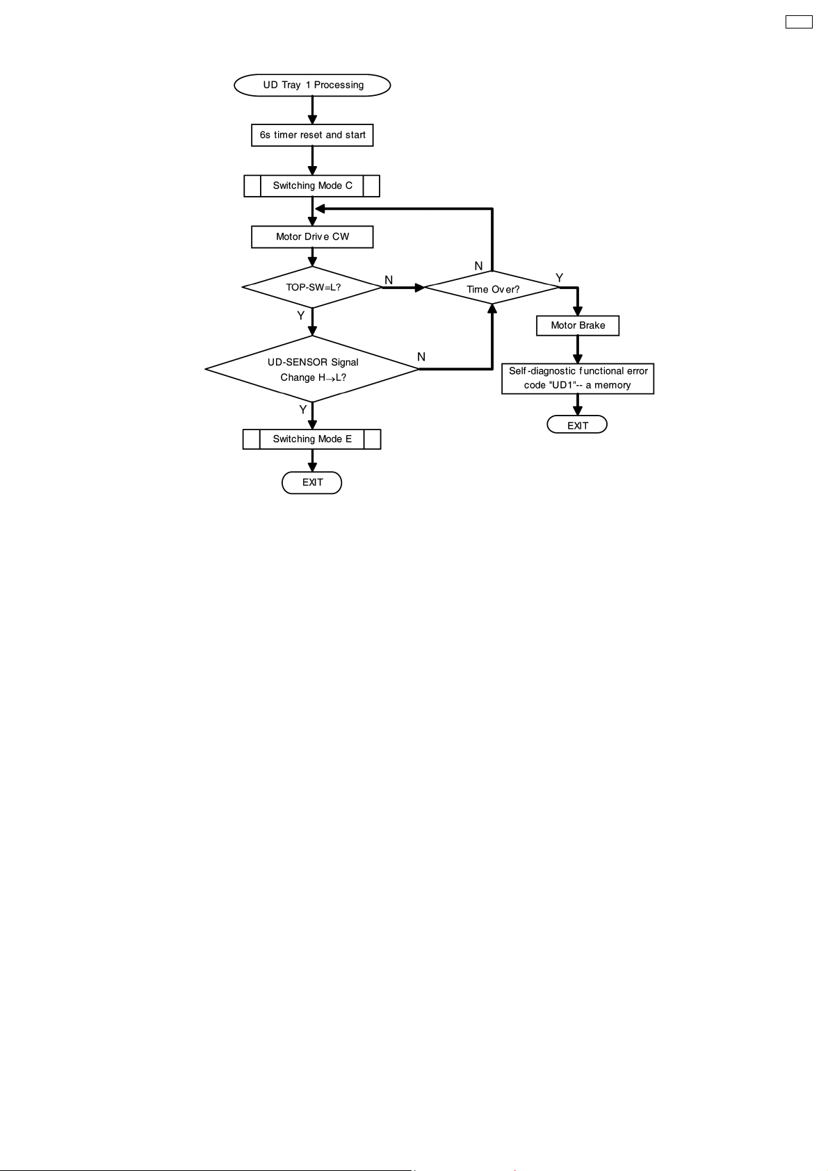
· For tray 1 selection, flow chart below will be used.
28
Page 29
CRS1
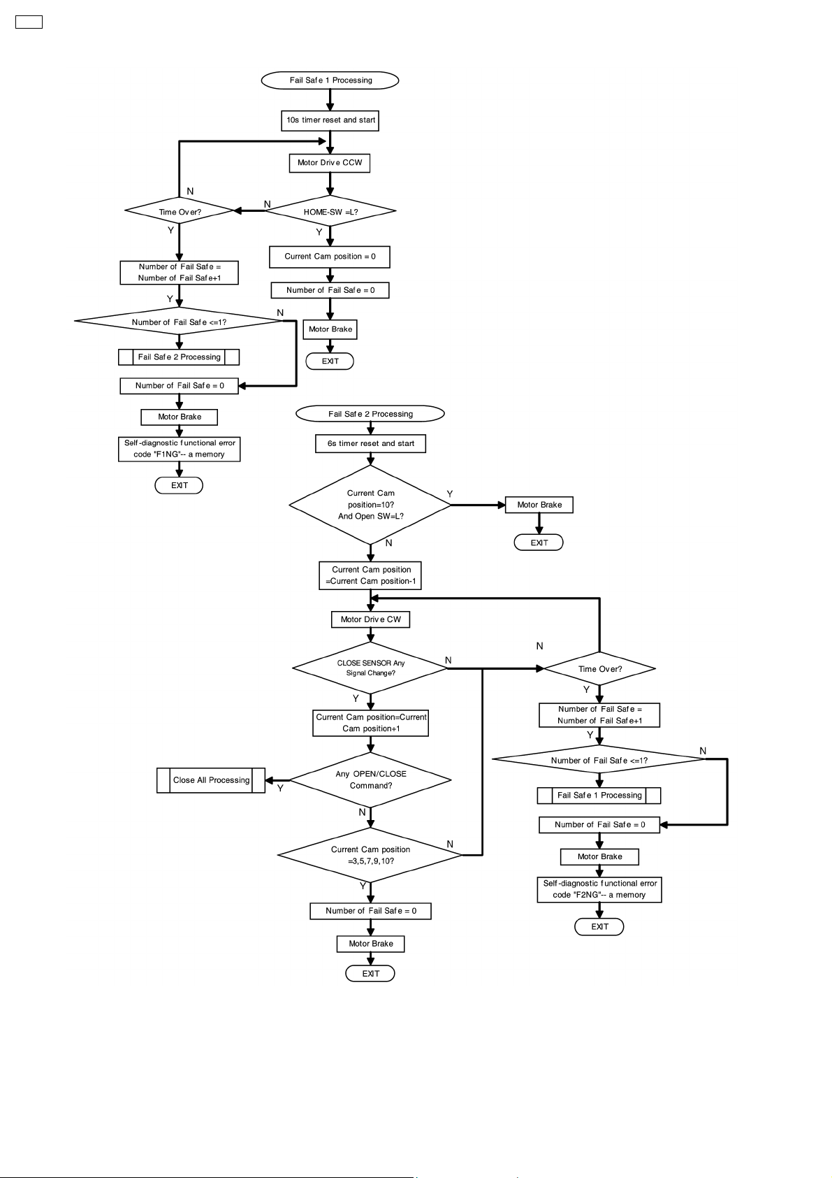
3.13. Fail Safe
· Fail safe function is for purpose of recovery of tray movement if the mechanism is not able to carry out tray open or close within
a specified time.
Fail safe 1: Tray can not open: Fail safe - move all trays to home position
Fail safe 2: Tray can not close: Fail safe - move to next close sensor transition position
Note : For Fail safe 2 :
1. If done on tray 1 - will fully go to Open position because OC gears are fully engaged
2. If done on either one of the remaining trays (2, 3, 4 & 5) - will only release the gear engagement and leave the tray at free
condition, tray can only open manually by user.
After fail safe, any subsequent button pressed on main set, the mechanism must follow "GO HOME" flowchart.
· Fail safe flow chart are shown as below:
29
Page 30
CRS1
3.14. Manual Trigger Tray Close
· W hen user push open tray at full open position, user may able to activate tray to be all close. This function will be disable if user
happen to press "OPEN/CLOSE" button and fail safe happen before.
30
Page 31

3.15. Changer Error Code
· The error code summary of CRS1 changer is as below:
Error Code Operation
IHMS Cam gear rotate to HOME position
ICLS Cam gear rotate to Play Driving position to drive playing tray to STOCK position
ISTK Move tray drive rack to STOCK position (drive tray to STOCK position)
IPLY Move tray drive rack to PLAY position (drive tray to PLAY position)
ITOP Move UD rack R to front direction (raise UD base to top position)
IUDS After TOP-SW detect, UD rack move to tray 1 position
HOME After load tray to PLAY position, cam gear move to HOMEAfter unload to STOCK position, cam gear
move to HOME
After all tray close, cam gear go to HOME position
LOAD Tray move from STOCK to PLAY position
UNLD Tray move from PLAY to STOCK position
PDRV Cam gear move from HOME to Play Driving position
UDU UD base move at up direction (from tray 5 to tray 2)
UDD UD base move at down direction (from tray 1 to tray 5)
UD1 UD base move to tray 1
F1NG Fail safe 1 NG (Fail safe 1 unsuccessful then try Fail Safe 2 also unsuccesful)
F2NG Fail safe 2 NG (Fail safe 2 unsuccessful then try Fail Safe 1 also unsuccesful)
CRS1
31
Page 32

CRS1
4 Self diagnosis and special mode setting
This unit is equipped with functions for checking and inspecting namely: Self-Diagnostic and Test Mode.
4.1. Special Mode Table
Item FL Display Key Operation
Mode Name Description Front Key
Self -Diagnostic
Mode
CD Test Mode To enter into checking the
CD Auto
Adjustment
To enter into self
diagnostic checking for
main unit.
reliability of changer unit.
To check the CD auto
adjustment result for
FLOCK, TLOCK and
CLVS.
1. Select [ ] for TAPE mode (Ensure no
tape is inserted).
2. Press and hold [
seconds follow by [
To exit, press
unit or remote control.
1. Select [ ] for CD mode.
2. Press and hold [
seconds follow by [
To exit, press
unit or remote control.
In CD Test Mode:
1. Press [0] button on the remote control.
To exit, press
unit or remote control.
]button for 3
].
button on main
] button for 3
].
button on main
button on main
CD Changer
Reliability Test
(CRS1)
Doctor Mode To enter into Doctor
Cold Start To activate cold start
Changer
Reliability Test
FL Display Test To check the FL
To determine the
reliability of CD Changer
Unit.
(For more information,
refer to section 4.1.1)
Mode for checking of
various items and
displaying EEPROM and
firmware version.
upon next AC power up.
To check the function
operation of changer unit.
(For more information,
refer to 4.1.1)
segments display (All
segments will light up and
LED will blink at 0.5
second interval)
1.
2.
1. All segments will light up for 1 second.
2. The Check Sum of EEPROM and firmware
version will be display.
* ROM correction
** Firmware version No:
In Self-Diagnostic Mode:
1. Select [
2. Press [
To exit, press
unit or remote control.
(The tray will return to PLAY position and then
power off)
In any mode:
1. Press [
by [4] and [7] on remote control.
To exit, press [ENTER] button on remote
control or
or remote control.
In doctor mode:
1. Press [4] button on remote control.
To exit, press [ENTER] button on remote
control or
or remote control.
In doctor mode:
1. Press [DISC] on remote control.
To exit, press [ENTER] button on remote
control or
or remote control.
In doctor mode:
1. Press [PROGRAM] button on remote
control.
] for CD mode.
] button.
button on main
] button on main unit follow
button on main unit
button on main unit
button on main unit
32
Page 33

Item FL Display Key Operation
Mode Name Description Front Key
Tape Eject Test To check on the tape
eject function (For deck
1/2)
In doctor mode:
1. Press [PROGRAM] button on remote
4.1.1. CD changer unit ageing test mode
Below is the process flow chart of ageing for the CD changer unit.
CRS1
control.
33
Page 34

CRS1
4.2. Error code Table
Self-Diagnosis Function (refer Section 4.1) provides information on any problems occuring for the unit and its respective
components by displaying the error codes. These error code such as U**, H** and F** are stored in memory and held unless it is
cleared.
34
Page 35

The error code is automatically display after entering into self-dia gnostic mode.
Error Code Diagnosis Contents Description of error Automatic FL Display Remarks
IHMS Cam gear
abnormality
Cam gear does not
rotate to “HOME”
position.
For CD changer unit (CRS1).
Press [SINGLE CHANGE] on main unit
for next error.
CRS1
ICSL Cam gear/gear units
abnormal
Cam gear does not
rotate to “PLAY” driving
position and hence does
not drive playing tray to
“STOCK” position.
ISTK Drive rack/gear
assembly abnormal
The tray drive rack does
not move to “STOCK”
position. (Tray does not
move to “STOCK”
position)
IPLY Drive rack/gear
assembly abnormal
The tray drive rack does
not move to “PLAY”
position. (Tray does not
move to “PLAY” position)
ITOP UD assembly UD Rack does not move
to front direction. This
lead to UD base not
raise to top position.
For CD changer unit (CRS1).
Press [SINGLE CHANGE] on main unit
for next error.
For CD changer unit (CRS1).
Press [SINGLE CHANGE] on main unit
for next error.
For CD changer unit (CRS1).
Press [SINGLE CHANGE] on main unit
for next error.
For CD changer unit (CRS1).
Press [SINGLE CHANGE] on main unit
for next error.
IUDS UD assembly After TOP SW is
detected, UD rack does
not move into tray 1
position.
HOME Cam gear/gear
assembly abnormal
Cam gear does not
move to “HOME”
position under following
conditions
1. After tray is load to
“PLAY” position.
2. After tray is unload
to “STOCK” position.
For CD changer unit (CRS1).
Press [SINGLE CHANGE] on main unit
for next error.
For CD changer unit (CRS1).
Press [SINGLE CHANGE] on main unit
for next error.
35
Page 36

CRS1
Error Code Diagnosis Contents Description of error Automatic FL Display Remarks
LOAD Tray drive assembly
abnormal
Tray unit does not move
from “STOCK” to “PLAY”
position
For CD changer unit (CRS1).
Press [SINGLE CHANGE] on main unit
for next error.
PDRV Cam gear/gear
assembly abnormal
UDU UD base asssembly
abnormal
UDD UD base asssembly
abnormal
UD1 UD base asssembly
abnormal
F1NG Fail - safe mode. (For
open/close tray
unit(s))
Cam gear does not
move from “HOME” to
“PLAY” drive position.
UD Base assembly does
not move upwards from
tray 5 to tray 2
UD Base assembly does
not move downwards
from tray 1 to tray 5.
UD Base assembly does
not move to tray 1.
When the tray open
operation is performed, it
fails to open. It will
automatically close all
trays after the time-out
by the microprocessor.
During this time when it
fails, the error code will
appear.
For CD changer unit (CRS1).
Press [SINGLE CHANGE] on main unit
for next error.
For CD changer unit (CRS1).
Press [SINGLE CHANGE] on main unit
for next error.
For CD changer unit (CRS1).
Press [SINGLE CHANGE] on main unit
for next error.
For CD changer unit (CRS1).
Press [SINGLE CHANGE] on main unit
for next error.
For CD changer unit (CRS1).
Press [SINGLE CHANGE] on main unit
for next error.
F2NG Fail - safe mode. (For
open/close tray
unit(s))
SRVC_TRV To unlock the
traverse unit for
service
RSET Cam gear jam/close
sensor faulty
When the tray close
operation is performed, it
fails to close. It will
automatically open all
trays after the time-out
by the microprocessor.
During this time when it
fails, the error code will
appear.
1. All trays set to
“STOCK” position
2. Mechanism set to
tray 5
3. Cam gear set to
“HOME” position
During tray re-open, the
cam gear will rotate in
the opposite direction to
reset the cam
gearposition. When it
fails, the error code will
appear.
For CD changer unit (CRS1).
Press [SINGLE CHANGE] on main unit
for next error.
For CD changer unit (CRS1).
Press [SINGLE CHANGE] on main unit.
For CD changer unit (CRS1).
Press [SINGLE CHANGE] on main unit
for next error.
CRS1 Error Code display
1. The errors that occured in CRS1 Mechanism can be recalled and displayed, in the order of the occurence under self-diagnostic
(Refer to Section 4.1 for procedures to enter this mode.
· Only the first 5 errors will be memorized (in backup memory). The subsequence error shall be ignored and not memorize.
For system with EEPROM as memory backup,memory space in EEPROM is neccesary.
2. To display all error code memorized
36
Page 37

In CRS1 Self-Diagnostic mode, press [SINGLE CHANGE] to display subsequence error code.
It shall repeat after reaching error no. 5.
e.g.:
[1____IHMS]→ [SINGLE CHANGE]
[2____ITOP]→ [SINGLE CHANGE]
[3____HOME]→ [SINGLE CHANGE]
[4____LOAD]→ [SINGLE CHANGE]
[5_____UDD]→ [SINGLE CHANGE]
3. To clear the error code memory
In CRS1 Self-Diagnostic mode, long press [SINGLE CHANGE] key (2s or more)
CRS1
37
Page 38

CRS1
5 Troubleshooting Explorer
5.1. Preparation of service jig
· This unit has a gear which is used for checking items
(open/close of disc tray, up/down operation of traverse unit
by manually) when servicing. (For gear information, that is
described on the items for disassembly procedures.)
· For preparation of gear (for servicing), perform the
procedures as follows.
· In case of re-servicing the same set, the “gear for servicing”
may be took off becaus e it had been used. So, the “gear for
servicing” must be stored.
5.3.1. No CD in the tray
Step 1: Check any disc tray at the play position from the
mechanism side.
5.2. Checking of Changer Unit
Below is the procedures for checking the function of the
changer unit.
Step 1: Enter into doctor mode.
Step 2: Press [DISC] on remote control unit.
Step 3: Error code will appear if there is any function problems.
(Pls refer to section 4.2 on more information of error code).
5.3. Setting the trays in "STOCK"
position
· Below is procedures for setting the main unit into service
mode:-
1. Enter into self-diagnostic (Refer to section 4.1)
2. Press [SINGLE CHANGE] on main unit.
· If fail to set the main unit into service mode, do it manua lly
by the below procedures
Step 2: Press the 2 claws and then lift up the top cover as
arrows shown.
Caution: Do not exert strong force on the claws.
38
Page 39

CRS1
Step 3: Release the top cover from the tray rear stopper
as arrow shown and remove the top cover.
Step 4: Remove the open lever spring.
Step 5: Insert the service gear into the service hole and
rotate the gear anti-clockwise.
Step 6: Press and hold the plunger lever and rotate the
gear clockwise until it stop.
39
Page 40

CRS1
Step 7: Release the plunger lever, rotate the gear clockwise
continuously until it stop at “HOME” position.
Step 8: Install the open lever spring as shown.
Step 9: Install the top cover, fix the top cover hook to the
tray rear stopper as arrow shown.
Step 10: Fix the top cover as arrow shown, the 2 claws
should be latched.
40
Page 41

5.3.2. When CD in the tray
CRS1
Step 1: Check any disc tray at the play position from the
mechanism side.
Step 2: Press the 2 claws and then lift up the top cover as
arrows shown.
Caution: Do not exert strong force on the claws.
Step 3: Release the top cover from the tray rear stopper
as arrow shown and remove the top cover.
Step 4: Remove the open lever spring.
41
Page 42

CRS1
Step 7: Push forward and remove the gear cover as arrow
shown.
Step 5: Press the claw, push backwards and remove the
trigger slide plate as arrows shown.
Step 6: Prepare the service key for use.
Step 8: Remove the open switch lever.
42
Page 43

CRS1
Step 9: Remove the OC gear assy followed by the OC
gear spring as arrow shown.
Caution: Ensure the OC gear assy and OC gear spring
are handle properly and keep them in a safe place.
Step 10: Insert the service key into the hole.
Step 11: Turn the service key to release the tray lock lever.
43
Page 44

CRS1
Step 12: Push the disc trays towards the front as arrow
shown.
Step 13: Turn the service key back to its original position
and remove it.
Step 14: Remove the disc.
Step 15: Push the disc trays back to the unit as arrow
shown.
44
Page 45

CRS1
Step 16: Install the OC gear assy followed by the OC gear
spring.
Step 17: Install the open switch lever.
Step 18: Install the gear cover as arrow shown.
45
Page 46

CRS1
Step 21: Release the plunger lever, rotate the gear
clockwise continuously until it stop at “HOME” position.
Step 19: Insert the service gear into the service hole and
rotate the gear anti-clockwise.
Step 20: Press and hold the plunger lever and rotate the
gear clockwise until it stop.
Step 22: Install the trigger slide plate as arrows shown in
sequence.
46
Page 47

Step 23: Install the open lever spring as shown.
CRS1
Step 25: Fix the top cover as arrow shown, the 2 claws
should be latched.
Step 24: Install the top cover, fix the top cover hook to the
tray rear stopper as arrow shown.
47
Page 48

CRS1
48
Page 49

6 Flow Chart
6.1. Disassembly Flow Chart
The following chart is the procedure for disassembling the casing and inside parts for internal inspection when carrying out the servicing.
7.1.1 UD Base Assembly
Step 1: Press the 2 claws downward and push the top
cover backwards and lift up the top cover to
remove it.
Step 2: Release the top cover from the tray rear stopper
and remove the top cover.
7.1.7 Traverse Unit
Step 1: Press and hold the plunger lever and
rotate the gear until it stop.
Step 2: Push the traverse slide plate to release
the traverse unit.
Step 3: Remove the traverse unit.
7.1.8 Limit Spring
Step 1: Remove the limit spring.
7.1.9 Play Lever Spring
Step 1: Remove the play lever spring.
Step 3: Remove the open lever spring from the gear cover.
Step 4: Push forwards and remove the gear cover.
Step 5: Remove the open switch lever.
Step 6: Remove the OC gear assy followed by the OC
gear assy.
Step 7: Press the claw, push backwards and remove the
trigger slide plate.
Step 8: Use a minus screwdriver slot into the gap and
push out the tray lock lever.
Step 9: Push the disc trays towards the front.
Step 10: Turn the UD connection lever clockwise.
Step 11: Push the claw and slide the UD rack L.
Step 12: Press and hold the claw at the pitch plate then push
the UD rack R.
Step 13: Remove the UD base assembly.
7.1.2 DiscTrays
UD connection lever
Step 1: Remove the UD connection lever.
Step 2: Push the claw and remove the lock lever 1.
Step 3: Push the tray drive rack to hit the stopper.
Step 4: Push the 5 disc trays until it stop.
Step 5: Lift up slightly and push the 5 disc trays further.
Step 6: Tilt and remove the 5 disc trays.
7.1.3 CD Loading Unit
Play lever B
Step 1: Push the UD rack L forwards.
Step 2: Position the tray drive rack in the center.
Step 3: Push the play lever B and lift up the rib slightly to
remove the play lever B.
Tray drive rack
Step 4: Release the claw and then slide and remove the tray
drive rack.
UD rack L
Step 5: Push the claw.
Step 6: Slide the UD rack L.
Step 7: Lift up the unit.
Step 8: Follow the groove to lift up and remove the UD rack L.
UD rack R
Step 9: Slide the UD rack R until it stop.
Step 10: Press the claw.
Step 11: Continue to slide the UD rack R until it stop.
Step 12: Lift up the UD rack R and slide backwards to stop
at the stopper.
Step 13: Remove the UD rack R.
Trigger gear
Step 14 Turn the trigger gear clockwise and remove it.
Pitch plate
Step 15: Release 3 screws.
Step 16: Remove 4 claws in order followed by detach the pitch
plate.
Lock lever 2
Step 17: Release the claw and pull out the lock lever 2.
Change spring
Step 18: Remove the change spring.
Pulley gear and belt
Step 19: Remove the belt and pull out the pulley gear.
Gears
Step 20: Remove relay gear 1, relay gear 3, UD gear 2, long
gear, play gear 2 and tray gear in order.
Step 21: Remove relay gear 2, switching gear, UD gear 1 in
order.
Cam gear
Step 22: Remove cam gear.
Function gear and main drive gear
Step 23: Remove main drive gear and function gear.
Play gear 1
Step 24: Remove play gear 1.
Function lever
Step 25: Remove the function lever from the ribs.
Step 26: Release the spring from the ribs to remove the play
switch lever.
CRS1
7.1.10 Pitch Plate Assembly
Step 1: Slide the UD rack L backwards, push
the claw.
Step 2: Slide the UD rack R until it stop.
Step 3: Press the claw.
Step 4: Push the claw, then turn the trigger
gear clockwise and remove it .
Step 5: Remove 3 screws.
Step 6: Release 4 claws in order followed by
detach the pitch plate.
7.1.4 CD Loading P.C.B.
Step 1: Turn over the unit and remove 4 screws
from the CD loading P.C.B.
Step 2: Unsolder the 4 points.
Step 3: Release the claw.
Step 4: Remove the CD Loading P.C.B.
Plunger assembly
Step 5: Remove the plunger assembly by using
a minus screw driver.
7.1.5 Plunger Lever
Step 1: Remove the switching gear.
Step 2: Install the pitch plate.
Step 3: Lift up the plunger lever in 90 degree.
Step 4: Remove the plunger lever in 90 degree
position.
7.1.6 Motor Unit
Step 1: Push the motor unit to remove it.
49
Page 50

CRS1
6.2. Assembly Flow Chart
The following chart is the procedure for assembling the casing and inside parts for internal inspection when carrying out the servicing.
7.2.1 CD Loading Unit
Plunger lever
Step 1: Turn over the unit and install the plunger lever in 90
degree position.
Step 2: Push in the plunger lever.
Step 3: Turn over the unit and install the motor unit properly.
Plunger assembly
Step 4: Install the plunger assembly.
CD loading P.C.B.
Step 5: Install the CD Loading P.C.B.
Step 6: The claws should be latched.
Step 7: Solder the 4 points.
Step 8: Fix it with 4 screws.
Play switch lever
Step 9: Install the play switch lever.
Step 10: Fix the spring below the rib.
Function lever
Step 11: Install the the function lever.
Play gear 1
Step 12: Install the play gear 1.
Function gear and main drive gear
Step 13: Install the main drive gear.
Step 14: Install the function gear.
Gears
Step 15: Install the relay gear 2, switching gear and UD gear 1
respectively.
Step 16: Install the cam gear.Make sure the big hole is fix at the
position (A) at 90 degree.
Step 17: Turn the cam gear anti-clockwise until the big hole
stop at position (B).
Step 18: Install the relay gear 1, relay gear 3, UD gear 2, long
gear and play gear 2 respectively.
Step 19: Install the tray relay gear.
Pulley gear and belt
Step 20: Install the pulley gear followed by the belt.
Change spring
Step 21: Install the change spring.
Pitch plate
Step 22: Install the lock lever 2 in sequence.
Step 23: Install the pitch plate.
Step 24: The 4 claws should be latched properly.
Step 25: Fix it with 3 screws.
Trigger gear
Step 26: Install the trigger gear in sequence.
Step 27: Use the screwdriver to turn the hole
on the UD gear 2 align with the pitch
plate hole.
UD rack R
Step 28: Insert the UD rack R.
Step 29: Push the UD rack R.
UD rack L
Step 30: Insert the UD rack L.
Step 31: Push the claw.
Step 32: Pull the UD rack L.
Tray drive rack
Step 33: Install the tray drive rack.
Play lever B
Step 34: Install the play lever B below the rib.
7.2.2 Disc Trays
Step 1: Tilt and fix the 5 disc trays.
Step 2: Push the 5 disc trays until it stop.
Step 3: Push the tray drive rack until it stop.
Lock lever 1
Step 4: Fix the lock lever 1 onto the pitch plate.
Step 5: Press and hold the claw at the pitch plate then push
the UD rack R.
Step 6: Push the claw and slide the UD rack L.
UD connection lever
Step 7: Install the UD connection lever.
7.2.3 UD Base Assembly
Step 1: Push the traverse slide plate.
Step 2: Install the UD base assembly.
Step 3: Turn UD connection lever anti-clockwise,
the UD base assembly will move downwards.
Step 4: Install the tray lock lever to the mechanism base
and push the tray lock lever with a hand to fix it.
Step 5: Push the disc trays back to the unit.
Trigger Slide Plate
Step 6: Install the trigger slide plate, push forwards and
push the trigger until locked by the claw.
Step 7: Install the OC gear spring followed by the OC gear
assy.
Step 8: Install the open switch lever.
Step 9: Install the gear cover.
Step 10: Install the open lever spring.
Step 11: Install the top cover, fix the top cover hook to
the tray rear stopper.
Step 12: Fixed the top cover, the 2 claws should be latched.
7.2.5 Traverse Unit
Step 1: Turn over the unit and install traverse unit.
Step 2: Push the traverse slide plate to lock the
traverse unit.
7.2.4 CD Loading P.C.B
Step 1: Install the plunger assembly.
Step 2: Install the CD Loading P.C.B.
Step 3: The claw should be latched.
Step 4: Fix it with 4 screws.
Step 5: Solder the 4 points.
50
Page 51

6.3. Disassembly Flow
CRS1
1. Top Cover
10. UD Connection
Lever
19. Screw
28. Relay Gear 3
2. Open Lever Spring
11. Lock Lever 1
20. Pitch Plate
29. Relay Gear 1
3. Gear Cover
12. Tray
21. Change Spring
30. Cam Gear
4. Open Switch Lever
13. Play Lever B
22. Belt
31. UD Gear 1
5. OC Gear Spring
14. Tray Drive Rack
23. Pulley Gear
32. Switching Gear
6. OC Gear Assy
15. UD Rack L
24. Tray Relay Gear
33. Relay Gear 2
7. Trigger Slide Plate
16.UD Rack R
25. Play Gear 2
34. Function Gear
8. Tray Lock Lever
17. Trigger Gear
26. Long Gear
35. Main Drive Gear
9. UD Base Assy
18. Lock Lever 2
27 UD Gear 2
36. Play Gear 1
37. Play Switch Lever
38. Function Lever
39. Screw
40. CD Loading
PCB
41. Plunger Lever
51
42. Mech Base
43. Play Lever Spring
44. Limit Spring
Page 52

CRS1
52
Page 53

7 Assembling and Disassembling Procedure.
7.1. Disassembling Procedures
Caution:
Do ensure that the main unit is set to service mode before repair.
For information on setting to service mode for changer unit, pls refer to section 5.3.
Note:
Change unit (CRS1) reliability test must be carry out in complete unit or using the Service P.C.B (Refer section 8).
7.1.1. Disassembly of UD Base Assembly
CRS1
Step 1: Press the 2 claws downwards and push the top
cover backwards and lift up the top cover to remove it.
Caution: Do not exert strong force on the claws when
pressing the claws.
Step 3: Remove the open lever spring from the gear cover.
Caution: Ensure the open lever spring is handle
properly and keep it in a safe place.
Step 4: Push forwards and remove the gear cover as
arrow shown.
Step 2: Release the top cover from the tray rear stopper
as arrow shown and remove the top cover.
53
Page 54

CRS1
Step 7: Press the claw, push backwards and remove the
trigger slide plate as arrows shown.
Step 5: Remove the open switch lever.
Step 6: Remove the OC gear assy followed by the OC
gear spring as arrow shown.
Caution: Ensure the OC gear assy and OC gear spring
are handle properly and keep them in a safe place.
Step 8: Use a minus screwdriver slot into the gap and
push out the tray lock lever as arrows shown.
Caution: Do not exert force as it may cause damage to
the tray lock lever.
54
Page 55

Step 9: Push the disc trays towards the front as arrow
shown.
CRS1
Step 11: Push the claw and slide the UD rack L as arrows
shown.
Step 12: Press and hold the claw at the pitch plate then
push the UD rack R as arrows shown.
Step 10: Turn the UD connection lever clockwise.
55
Page 56

CRS1
Step 13: Remove the UD base assembly as arrow shown.
7.1.2. Disassembly of Disc Trays
· Follow the (Step 1) to (Step 13) of item 7.1.1. (Disassembly
of UD Base Assembly)
Step 1: Remove the UD connection lever.
· Disasse mbly of UD connection lever
Step 2: Push the claw as arrow shown and remove the
lock lever 1.
Caution: Do not exert force as it may cause the claw to
be damage.
56
Page 57

CRS1
Step 3: Push the tray drive rack as arrow shown to hit the
stopper.
Step 4: Push the 5 disc trays as arrow shown until it stop
(bottom picture).
57
Page 58

CRS1
Step 5: Lift up slightly and push the 5 disc trays further as
arrows shown.
Step 6: Tilt and remove the 5 disc trays as arrows shown.
7.1.3. Disassembly of CD Loading Unit
· Follow the (Step 1) to (Step 13) of item 7.1.1. (Disassembly
of UD Base Assembly)
· Follow the (Step 1) to (Step 6) of item 7.1.2. (Disassembly
of Disc Trays)
· Disasse mbly of play lever B
58
Page 59

CRS1
Step 1: Push the UD rack L forwar ds as arrow shown.
Step 2: Position the tray drive rack in the center.
Step 3: Push the play lever B and lift up the rib slightly to
remove the play lever B as arrows shown.
Caution: Make sure do not break the rib when
removing the play lever B. The rib break easily by
using the tools.
· Disasse mbly of tray drive rack
Step 4: Release the claw as arrow shown (top picture) then
slide and remove the tray drive rack as arrow shown
(bottom picture).
· Disasse mbly of UD rack L
59
Page 60

CRS1
Step 5: Push the claw as arrow shown.
Step 6: Slide the UD rack L as arrow shown.
Step 7: Lift up the unit as shown.
Step 8: Follow the groove to lift up and remove the UD
rack L as arrow shown.
· Disasse mbly of UD rack R
60
Page 61

CRS1
Step 9: Slide the UD rack R as arrow shown until it stop.
Step 10: Press the claw as arrow shown.
Step 11: Continue to slide the UD rack R as arrow shown
until it stop.
Step 12: Lift up the UD rack R and slide backwards to stop
at the stopper.
Step 13: Remove it as arrow shown.
· Disasse mbly of trigger gear
61
Page 62

CRS1
Step 14: Turn the trigger gear clockwise and remove it as
arrows shown.
Step 16: Release 4 claws as arrows shown in order
followed by detach the pitch plate.
· Disasse mbly of lock lever 2
· Disasse mbly of pitch plate
Step 15: Remove 3 screws
Step 17: Release the claw and pull out the lock lever 2 as
arrows shown. (The rib is fragile, do not exert force on it).
· Disasse mbly of change spring
62
Page 63

Step 18: Remove the change spring.
Caution: Handle the change spring carefully, do not
lose it. Put in a proper storage location.
CRS1
· Disasse mbly of pulley gear and belt
Step 19: Remove the belt and pull out the pulley gear.
· Disasse mbly of gears
63
Page 64

CRS1
Step 20: Remove the relay gear 1, relay gear 3, UD gear 2,
long gear, play gear 2 and tray relay gear in order.
Step 21: Remove relay gear 2, switching gear, UD gear 1
in order.
· Disasse mbly of cam gear
Step 22: Remove cam gear.
· Disasse mbly of function gear and main drive gear
64
Page 65

CRS1
Step 23: Remove main drive gear and function gear.
· Disasse mbly of play gear 1
Step 24: Remove play gear 1.
· Disasse mbly of function lever
65
Page 66

CRS1
7.1.4. Disassembly of CD Loading P.C.B.
Step 25: Remove the function lever from the ribs as arrow
shown.
Step 26: Release the spring from the rib as arrow shown
to remove the play switch lever.
Note: For changing of the mecha chassis, please
follow Step 1 to Step 5 of item 7.1.4 (Disassembly
of CD Loading P.C.B.), Step 3 to Step 4 of item 7.1.5
(Disassembly of Plunger Lever) and Step 2 of item
7.1.6 (Disassembly of Motor Unit)
Step 1: Turn over the unit and remove 4 screws from the
CD Loading P.C.B.
Step 2: Unsolder the 4 points.
Step 3: Release 1 claw as arrow shown.
66
Page 67

CRS1
Step 4: Remove the CD Loading P.C.B. as arrows shown.
· Disasse mbly of plunger assembly
Step 5: Remove the plunger assembly by using a minus
screwdriver.
7.1.5. Disassembly of Plunger Lever
· Follow the (Step 1) to (Step 13) of item 7.1.1. (Disassembly
of UD Base Assembly)
· Follow the (Step 1) to (Step 6) of item 7.1.2. (Disassembly
of Disc Trays)
· Follow the (Step 1) to (Step 18) of item 7.1.3. (Disassembly
of CD Loading Unit)
· Follow the (Step 1) to (Step 5) of item 7.1.4. (Disassembly
of CD Loading P.C.B.)
67
Page 68

CRS1
Step 1: Remove the switching gear.
Step 2: Install the pitch plate.
Note: Ensure the pitch plate seats properly onto it.
Step 3: Lift up the plunger lever in 90°
68
Page 69

Step 2: Push the motor unit as arrow show to remove it.
CRS1
Step 4: Remove the plunger lever in 90° position.
7.1.6. Disassembly of Motor Unit
· Follow the (Step 1) to (Step 13) of item 7.1.1. (Disassembly
of UD Base Assembly)
· Follow the (Step 1) to (Step 6) of item 7.1.2. (Disassembly
of Disc Trays)
· Follow the (Step 1) to (Step 16) of item 7.1.3. (Disassembly
of CD Loading Unit)
· Follow the (Step 1) to (Step 4) of item 7.1.4. (Disassembly
of CD Loading P.C.B.)
7.1.7. Disassembly of Traverse Unit
Important notes: Ensure all the trays are in the “STOCK”
position before proceeding to the disassemble of traverse
unit. For procedures to set the trays in “STOCK” position,
please refer to (5. Troubleshooting Explorer)
Step 1: Remove the belt.
Step 1: Press and hold the plunger lever and rotate the
gear as arrows shown until it stop.
69
Page 70

CRS1
Step 1: Remove the limit spring as arrow shown.
Step 2: Push the traverse slide plate as arrow shown to
release the traverse unit.
Caution: Do not exert strong force on the traverse
slide plate.
7.1.9. Disassembly of Play Lever Spring
· Follow the (Step 1) to (Step 13) of item 7.1.1. (Disassembly
of UD Base Assembly)
· Follow the (Step 1) to (Step 6) of item 7.1.2. (Disassembly
of Disc Trays)
· Follow the (Step 1) to (Step 26) of item 7.1.3. (Disassembly
of CD Loading Unit)
Step 1: Remove the play lever spring as arrow shown.
Step 3: Remove the traverse unit as arrow shown.
7.1.8. Disassembly of Limit Spring
· Follow the (Step 1) to (Step 9) of item 7.1.1. (Disassembly
of UD Base Assembly)
7.1.10. Disassembly of Pitch Plate
Assembly
· Follow the (Step 1) to (Step 13) of item 7.1.1. (Disassembly
of UD Base Assembly)
· Follow the (Step 1) to (Step 6) of item 7.1.2. (Disassembly
of Disc Trays)
· Follow the (Step 1) to (Step 3) of item 7.1.3. (Disassembly
of CD Loading Unit)
70
Page 71

CRS1
Step 1: Slide the UD rack L backwards, push the claw as
arrow shown.
Step 2: Slide the UD rack R as arrow shown until it stop.
Step 3: Press the claw as arrow shown.
Step 4: Push the claw as arrow shown, then turn the
trigger gear clockwise and remove it as arrows shown.
71
Page 72

CRS1
Step 5: Remove 3 screws.
Step 6: Release 4 claws as arrows shown in order
followed by detach the pitch plate.
72
Page 73

7.2. Assembling Procedure
CRS1
7.2.1. Assembly of CD Loading Unit
· Assembly of Plunger Lever
· Assembly of Motor Unit
Step 1: Turn over the unit and install the plunger lever in
90° position.
Step 3: Turn over the unit and install the motor unit
properly.
· Assembly of Plunger Assembly
Step 2: Push in the plunger lever as arrow shown.
73
Page 74

CRS1
Step 4: Install the plunger assembly as arrow shown, the
catch should be latched.
· Assembly of CD Loading P.C.B.
Step 5: Install the CD Loadin g P.C.B. as arrows shown.
74
Page 75

Step 6: The claw should be latched.
CRS1
Step 7: Fix it with 4 screws.
Step 8: Solder the 4 points.
Step 9: Install the play switch lever.
· Assembly of play swtich lever
Step 10: Fix the spring below the rib as arrow shown.
· Assembly of function lever
75
Page 76

CRS1
Step 11: Install the function lever.
Note: Ensure the function lever seats properly onto
the ribs. A click sound will be heard when
installing.
· Assembly of play gear 1
Step 12: Install the play gear 1.
· Assembly of function gear and main drive gear
76
Page 77

CRS1
Step 13: Install the main drive gear.
Step 14: Install the function gear.
· Assembly of gears
Step 15: Install the relay gear 2, switching gear and UD
gear 1 respectively.
77
Page 78

CRS1
Step 16: Install the cam gear. Make sure the big hole is fix
at the position (A) at 90°
Step 17: Turn the cam gear anti-clockwise until the big
hole stop at position (B).
Step 18: Install the relay gear 1, relay gear 3, UD gear 2,
long gear and play gear 2 respectively.
Step 19: Install the tray relay gear.
· Assembly of pulley gear and belt
78
Page 79

Step 21: Install the change spring.
Caution: Handle the change spring carefully, do not
lose it. Ensure the change spring seats properly on
the groove of long gear.
CRS1
Step 20: Install the pulley gear followed by the belt.
Note: Do not apply the grease to the belt.
· Assembly of change spring
· Assembly of pitch plate
Step 22: Install the lock lever 2 as arrows whown in
sequence.
79
Page 80

CRS1
Step 25: Fix it with 3 screws
Step 23: Install the pitch plate.
· Assembly of trigger gear
Step 24: The 4 claws should be latched properly.
Step 26: Install the trigger gear in sequen ce.
Note: Ensure the trigger seats properly onto the
groove (cam gear).
80
Page 81

· Assembly of UD rack R
Step 27: Use the screwdriver to turn the hole on the UD
gear 2 align with the pitch plate hole.
CRS1
Step 28: Insert the UD rack R as arrow shown.
Step 29: Push the UD rack R as arrow shown.
· Assembly of UD rack L
Step 30: Insert the UD rack L as arrow shown.
Step 31: Push the claw as arrow shown.
81
Page 82

CRS1
Step 33: Install the tray drive rack as arrow shown.
Step 32: Pull the UD rack L as arrow shown.
· Assembly of tray drive rack
· Assembly of play lever B
Step 34: Install the play lever B below the rib.
82
Page 83

7.2.2. Assembly of Disc Trays
CRS1
Step 1: Tilt and fix the 5 disc trays as arrows shown.
Step 3: Push the tray drive rack as arrow shown until it
stop.
· Assembly of lock lever 1
Step 2: Push the 5 disc trays as arrow shown until it stop.
83
Page 84

CRS1
Step 5: Press and hold the claw at the pitch plate then
push the UD rack R as arrows shown.
Step 6: Push the claw and slide the UD rack L as arrows
shown.
Step 4: Fix the lock lever 1 onto the pitch plate as arrow
shown in sequence.
· Assembly of UD connection lever
84
Page 85

7.2.3. Assembly of UD Base Assembly
CRS1
Step 1: Push the traverse slide plate as arrow shown.
Step 7: Install the UD connection lever.
· Follow the (Step 1) to (Step 12) of item 7.2.3. (Assembly of
UD Base Assembly)
85
Page 86

CRS1
Step 3: Turn the UD connection lever anti-clockwise, the
UD base assembly will move downwards.
Note: When the UD connection lever is turn and the
UD base assembly did not move downwards, check for
step 1 to step 3 again.
Step 2: Install the UD base assembly.
Note: Ensure the UD base assembly seats properly into
the grooves and engage with the play lever B and tray
drive rack.
86
Page 87

CRS1
Step 4: Install the tray lock lever to the mechanism base
and push the tray lock lever with a hand to fix it.
Step 5: Push the disc trays back to the unit as arrow
shown.
· Assembly of Trigger Slide Plate
87
Page 88

CRS1
Step 6: Install the trigger slide plate, push forwards and
push the trigger gear as arrows shown until locked by the
claw.
Step 7: Install the OC gear spring followed by the OC gear
assy.
Caution: OC gear free to rotate after assembly
88
Page 89

Step 10: Install the open lever spring.
CRS1
Step 8: Install the open switch lever.
Step 9: Install the gear cover as arrow shown.
Step 11: Install the top cover, fix the top cover hook to the
tray rear stopper as arrow shown.
89
Page 90

CRS1
Step 12: Fix the top cover as arrow shown, the 2 claws
should be latched.
The mechanism unit will be ready to be checked using
service jig or be mounted to the main unit for checking.
7.2.4. Assembly of CD Loading P.C.B.
Step 1: Install the plunger assembly as arrow shown, the
catch should be latched.
90
Page 91

Step 3: The claw should be latched.
CRS1
Step 2: Install the CD Loadin g P.C.B. as arrows shown.
Step 4: Fix it with 4 screws.
Step 5: Solder the 4 points.
91
Page 92

CRS1
7.2.5. Assembly of Traverse Unit
Step 1: Turn over the unit and install the traverse unit.
Step 2: Push the traverse slide plate as arrow shown to
lock the traverse unit.
92
Page 93

8 CRS1 (Changer Unit) Ageing / Reliability
Purpose: It is necessary to test the mechanism unit by using the Service Jig P.C.B., make sure it works in order before
install it to the main unit.
8.1. Equipments
CRS1
93
Page 94

CRS1
9 Notes of Schematic Diagram
(All schematic diagrams may be modified at any time with
the development of new technology)
Note :
SW1 Open switch
SW2 Stock switch
SW3 Home switch
SW4 Top switch
SW5 Play switch
· The voltage value and waveforms are the reference voltage
of this unit measured by DC electro nic voltmeter (high
impedance) and oscilloscope on the basis of chassis.
Accordingly, there may arise some error in voltage values
and waveform s depending upon the internal impedance of
the tester or the measuring unit.
· Importance safety notice :
Components identified by
characteristics important for safety. Furthermore, special
parts which have purposes of fire-retardant (resistors), highquality sound (capacitors), low-noise (resistors), etc. are
used. When replacing any of components, be sure to use
only manuf acture r´s specified parts shown in the parts list.
Caution !
IC, LSI and VLSI are sensitive to static electricity.
Secondary trouble can be prevented by taking care during
repair.
· Cover the parts boxes made of plastics with aluminium foil.
· Put a conductive mat on the work table.
· Ground the soldering iron.
· Do not touch the pins of IC, LSI or VLSI with fingers directly.
mark have special
94
Page 95

10 Schematic Diagram
10.1. CD Loading Circuit
SCHEMATIC DIAGRAM - 1
CRS1
CD LOADING CIRCUIT
C0GAG0000007
LOADING MOTOR DRIVE
VREF
OUT2
RNF
23456
1
M1
M
SW4
TOP
124
3
PH1
SG233
UD SENSOR
R1
1K
4
3
IC1
OUT1VMVCC
41
32
SW5
PLAY
1
2
: +B SIGNAL LINE
IN1
GND
IN2
789
SW2
STOCK
SW1
OPEN
124
3
C1
16V100
SW3
HOME
PH2
SG233
CAM SENSOR
R2
390
41
32
CN1
CCW
1
CW
2
PGND
3
VCC_8V
4
HOME_SW
5
ST_SW
6
OPEN_SW
CAM_SENSOR
PLAY_SW
UD_SENSOR
BOTTOM_SW
DGND
SPEED
TO
7
MAIN
8
CIRCUIT
5V
9
10
11
12
13
14
95
Page 96

CRS1
11 Printed Circuit Board
11.1. CD Loading P.C.B.
ABCDEFG
1
A
CD LOADING P.C.B (REPX0439A)
SOLENOID
2
3
SW5
(PLAY)
412
3
4
5
6
7
8
12
34
PH1
(UD SENSOR)
14
13
12
11
10
9
8
7
6
5
4
3
2
1
CN1
9
8
7
6
5
4
3
2
1
IC1
SW4
(TOP)
2143
W7
W2
W1
W3
W5
W4
R2
W6
W8
R1
M1
M
C1
SERVICE JIG
PH2
(CAM SENSOR)
SW3
(HOME)
21
43
SW2
(STOCK)
0458A
PbF
0458A
SW1
(OPEN)
12
34
9
96
Page 97

12 Exploded Views
12.1. CD Loading Mechanism
CRS1
97
Page 98

CRS1
98
Page 99

CRS1
99
Page 100

CRS1
13 Replacement Parts List
Notes:
· Important safety notice:
Components identified by
Furthermore, special parts which have purposes of fire-retardant (resistors), high-quality sound (capacitors), low-noise
(resistors), etc. are used.
When replacing any of these components, be sure to use only manufacturers’s specified parts shown in the parts list.
· Capacitor values are in microfarad (µF) unless specified otherwise, P=Pico -farads(pF); Farads.
· Resistance values are in ohms, unless specified otherwise, 1K=1,000(ohms).
· The marking (RTL) indicates that the Retention Time is limited for this item. After the discon tinuatio n of this assembly in
production, the item will continue to be available for a specific period of time. The retention period of availability is dependant
on the type of assembly, and in accordance with the laws governing part and product retention. After the end of this period, the
assembly will no longer be available.
· [M] Indicates in the Remarks columns indicates parts that are supplie d by PAVCSG.
mark have special characteristics important for safety.
100
 Loading...