

Page 1
R
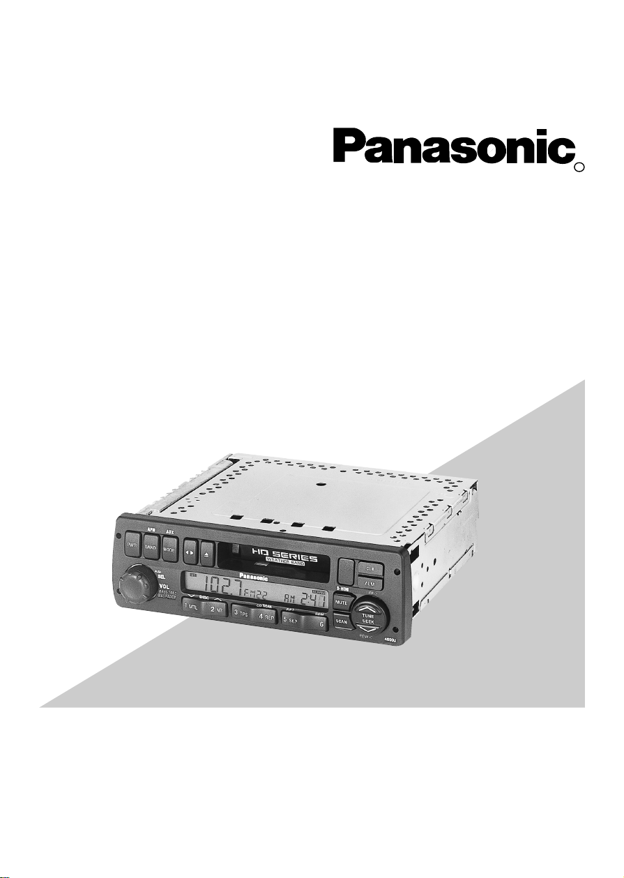
Heavy Duty Cassette/ Weather Band Receiver with Changer Control
CQ-4500U/CQ-4300U
Operating Instructions
Please read these instructions carefully before using this product and save this manual for future use.
Page 2
2
Panasonic welcomes you to our ever growing family of electronic product owners. We know that this
product will bring you many hours of enjoyment. Our reputation is built on precise electronic and
mechanical engineering, manufactured with carefully selected components and assembled by people
who take pride in their work. Once you discover the quality, reliability, and value we have built into this
product, you too will be proud to be a member of our family.
❏
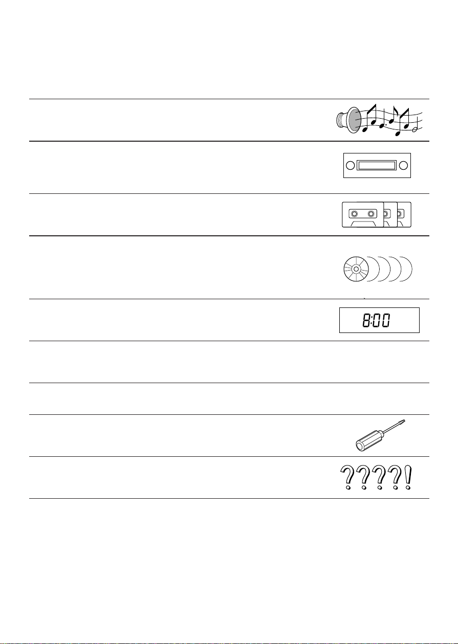
Use This Equipment Safely
When Driving
Keep the volume level low enough to be aware of road and traffic conditions.
When Washing Vehicle
Do not expose the equipment, including the speakers and tapes, to water or excessive moisture. This
could cause electrical shorts, fire, or other damage.
When Parked
Parking in direct sunlight can produce very high temperatures inside your vehicle. Give the interior a
chance to cool down before switching the unit on.
Use the Proper Power Supply
This equipment is designed to operate off a 12 volt, negative ground battery system (the normal system
in a North American vehicle.)
Protect the Tape Mechanism
Keep magnets, screwdrivers, or other metallic objects away from the tape mechanism and tape head to
prevent poor performance or malfunctions.
Use Authorized Service Centers
Do not attempt to disassemble or adjust this precision equipment. Please refer to the Servicenter list
included with this product for service assistance.
Notes:
• The two units can be connected to an optional CD changer (CX-DP801EUC, etc.), CQ-4500U can
be connected to an optional wired remote control unit (CA-RC300U).
• For connection and operation of CD changer (CX-DP801EUC, etc.) and wired remote control unit
(CA-RC300U), refer to the operating instructions of that unit.
• A wireless remote control unit (CA-RC500U) is optional for CQ-4500U.
• Optional wired remote control unit CA-RC300U can be connected to CQ-4500U.
Find the model number and serial number on either the back or bottom of the unit. Please record them
in the space below and retain this booklet as a permanent record of your purchase to aid in
identification in case of theft.
MODEL NUMBER SERIAL NUMBER
DATE PURCHASED FROM
CQ-4500U/CQ-4300U
Note: This operating instruction manual is for two models CQ-4500U and CQ-4300U.
The differences between these models are mentioned below. All illustrations throughout this manual
represent model CQ-4500U unless otherwise specified.
Model
Features
Wired remote control
Wireless remote control
AUX-IN
Temperture readout
S.HDB/LOUD
preamp-out
CQ-4500U
Yes
Yes
Yes
Yes
S
•
HDB
Yes
CQ-4300U
None
None
None
None
LOUD
None
Page 3
3
Contents
Use This Equipment Safely...................................................................Page 2
❏
Power and Sound Controls......................................................................4
How to adjust the volume, mute, balance, and tone for best listening
❏
Radio Basics..............................................................................................6
Mode selection, manual and automatic tuning, band selection,
preset stations
❏
Cassette Tape Player Basice....................................................................9
How to load, wind, play, and eject a cassette tape
❏
CD Changer Basics.................................................................................13
Play, repeat, random and scan, error messages.
Note: CD changer controls are applicable to units with optional CD changer
unit (sold separeately).
❏
Clock Basics............................................................................................15
Setting the time, selecting the clock display, alarm operation
❏
Temperature Reading.............................................................................17
❏
Casette Head Cleaning Warning............................................................17
❏
In Case of Malfunction............................................................................18
❏
Installation Guide....................................................................................19
Step-by-step procedures, electrical connections
❏
Troubleshooting......................................................................................28
Troubleshooting tips, where to get service help
Specifications .............................................................................................30
Part 15 of the FCC Rules............................................................................30
Page 4
4
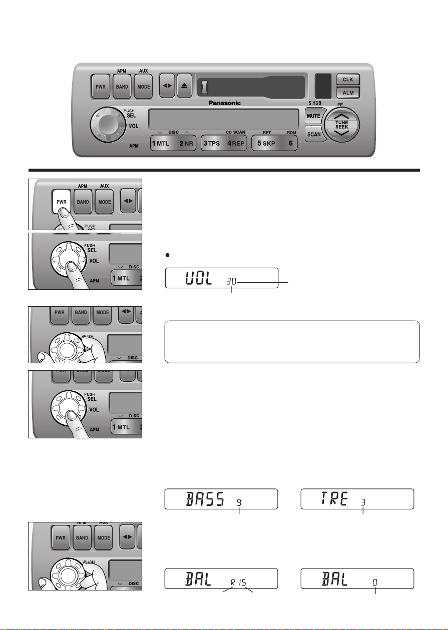
Power and Sound Controls
Power
If the vehicle is not running yet, turn the key in the ignition until the
accessory indicator lights.
Press
[PWR] to switch on the power.
Changing Audio Modes
Press this knob [SEL] to change the audio mode as follows.
VOL
a
BASS
a
TRE
(Volume) (Treble)
cd
FADE
b
BAL
(Fader) (Balance)
Volume
Press the knob to select the volume mode and then turn it
clockwise or counterclockwise to adjust the volume lev el.
Bass and Treble
Press the knob to select the BASS or TREBLE mode and then turn
it clockwise or counterclockwise to increase or decrease the
bass/treble level.
d
d
0 to 40
-12 to 12 -12 to 12
Volume Level
4500U
BASS/FAD
BAL/FADER
FEW
l
k
Anti-Volume-Blast Circuit
At power on, the volume returns to the previous level slowly if
the level was at 20 or higher.
Balance
Press the knob to select the BALANCE mode and then turn it
clockwise or counterclockwise to shift the sound volume to the right
or left speakers.
or L 1 to 15
Balance Center
(R: Right, L: Left)
BASS/FAD
BAL/FADER
BASS/FAD
BAL/FADER
Page 5
5
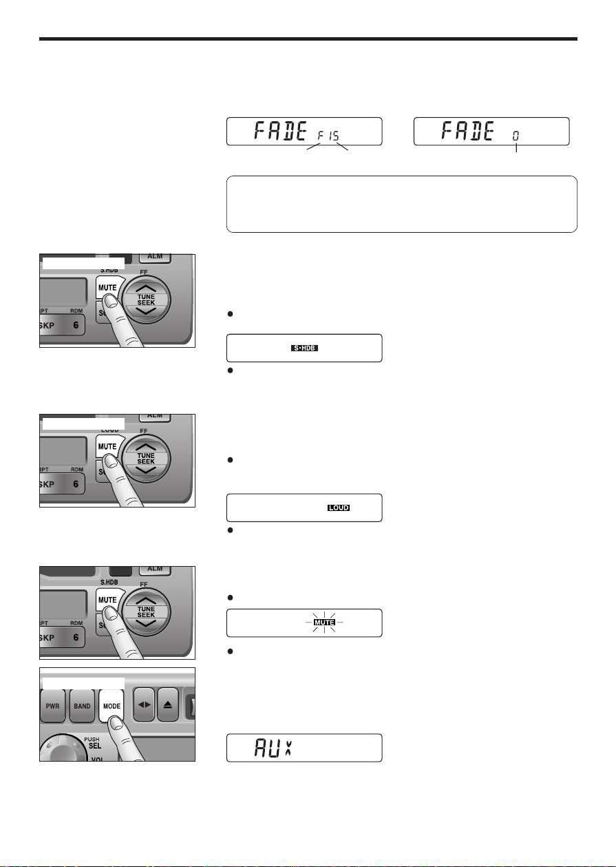
Fader
Press the knob to select the FADER mode and then turn it
clockwise or counterclockwise to shift the sound volume to the front
or rear speakers.
S•HDB (Super High Definition Bass)
(Only for CQ-4500U)
This featare enhances bass definition.
Press and hold [MUTE] (S•HDB) for more than 2 seconds to
activate high-defintion bass.
Press and hold [MUTE] (S•HDB) for more than 2 seconds to
cancel.
Tone Enhancement (Loudness)
(Only for CQ-4300U)
Press and hold [MUTE] (LOUD) for more than 2 seconds to
enhance bass and treble tones when listening at low or medium
volume.
Press and hold [MUTE] (LOUD) for more than 2 seconds again to
deactivate when listening at higher volumes.
Mute
Press [MUTE] to mute the sound completely.
Press [MUTE] again to cancel.
Selecting Auxiliary Source
(Only for CQ-4500U)
Press and hold [MODE] (AUX) for more than 2 seconds to select
AUX Input mode.
Connect the auxiliary equipment (any other appropriate
equipment) to the AUX IN Connector.
Canceling AUX Input mode
Press [MODE] (AUX) to resume the previous mode.
4500U
FEW
l
k
or R
(F: Front, R: Rear)
1 to 15
Fader Center
Press and hold
Press and hold
4300U
FEW
l
k
Note: In the audio mode (BASS/TRE/BAL/FADE), the display
will returm to regular operation mode when there is no input for
more than 5 seconds (2 seconds in the VOL mode).
Press and hold
FEW
l
k
4500U
Page 6
6
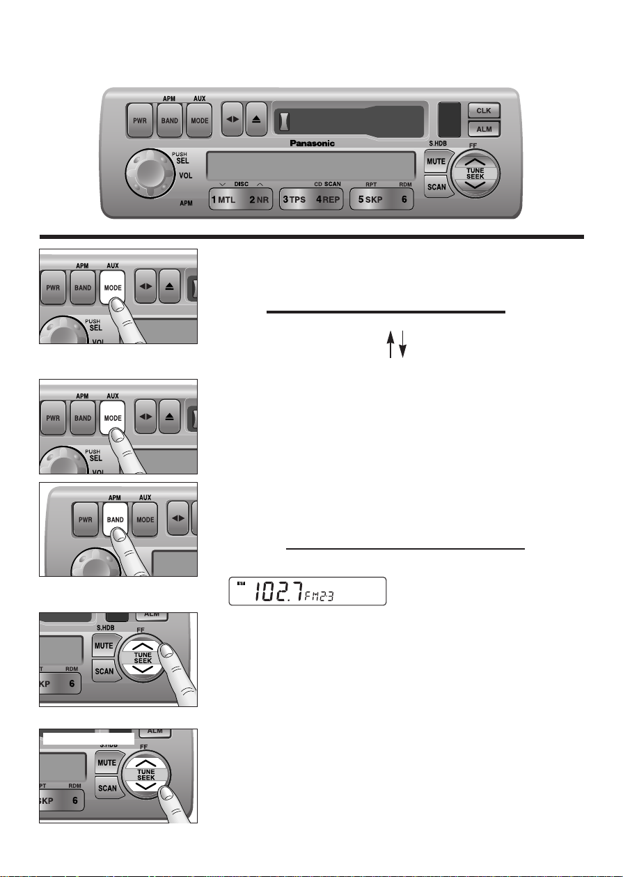
Radio Basics
Mode Selection
Press [MODE] to change the operation mode as follows.
Radio
a
Cassette
a
CD Changer (when connected)
cd
Press and hold [MODE] for more
than 2 seconds.
(AUX is only for CQ-4500U)
AUX
To change to the tuner mode
In case of CD changer mode or Tape mode, press [MODE].
Selecting a Band
Press [BAND] to change the band setting as follows.
FM1
a
FM2
a
W/B
a
AM
(Weather Band)
cd
"ST" indicator lights when FM stereo broadcast is available.
4500U
FEW
l
k
Manual Tuning
Press [TUNE jj] or [TUNE ii] to tune in a higher or lower
frequency.
Seek Tuning
Press and hold [SEEK jj] or [SEEK ii] for more than 0.5
seconds, then release it.
Seek tuning will automatically stop when a signal of the next
broadcast station is received.
Hold and release
BASS/FAD
BAL/FADER
l
k
FEW
4500U
FEW
l
k
4500U
Page 7
7
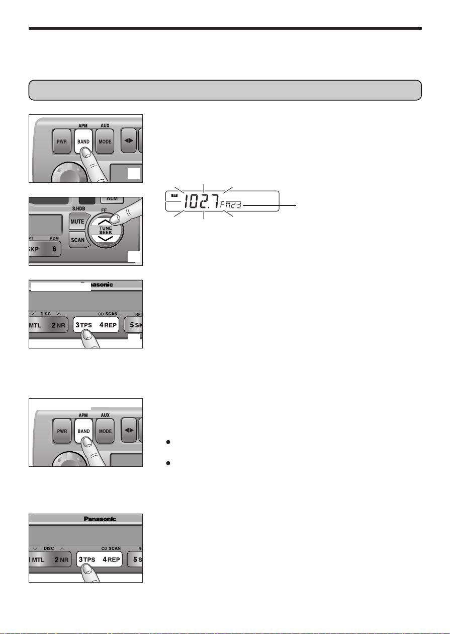
Station Preset
FM1, FM2, and AM can save maximum 6 stations each in their preset station memories.
Manual Station Preset
Press [BAND] to select a desired band.
Use manual or seek tuning to find a station to be stored in the
preset memory.
Press and hold one of the preset buttons [1] to [6] until the
display blinks once.
Note: You can change the memor y setting by repeating the above
procedure.
Tuning in a Preset Station
Press any of the buttons [1] to [6] to tune in the station preset by
the above.
Auto Station Preset
Select a band and press and hold [BAND] (APM: Auto Preset
Memory) for more than 2 seconds.
The 6 strongest available stations will be automatically saved in
the memory on preset buttons
[1] to [6].
Once set, the preset stations are sequentially scanned for 5
seconds each.
Note: Any stations preset previously on the selected band will be
erased.
d
d
Press and hold
Press and hold
Preset Number
Caution: To ensure safety, never attempt to preset stations while you are driving.
FEW
l
k
4500U
Page 8

8
Radio Basics
(continued)
Tuning in a Weather Band
Station
Press any of the buttons [1] to [6] to monitor the preset station.
Weather Band Stations
National Weather Radio Broadcasts from over 380 locations
throughout the U.S. on seven VHF/FM frequencies.
Tune to weather band to receive continuous weather information 24
hours a day on one of the following frequencies.
1. 162.550 MHz
2. 162.400 MHz
3. 162.475 MHz
4. 162.425 MHz
5. 162.450 MHz
6. 162.500 MHz
7. 162.525 MHz
Occasionally the frequency of an existing or planned station must
be changed because of unexpected radio frequency interference
with adjacent NOAA Weather Radio Stations and/or with other
Government or Commercial Operations within the area. If you have
a question concerning NOAA Weather Radio, please contact your
nearest National Weather Service Office.
Note: The weather band (CH1-6) has been preset. CH7 is
selected by pressing
[jj] or [ii].
WB
Weather Band Frequency (channel) Number
The frequency (162) remains unchanged.
Page 9
9
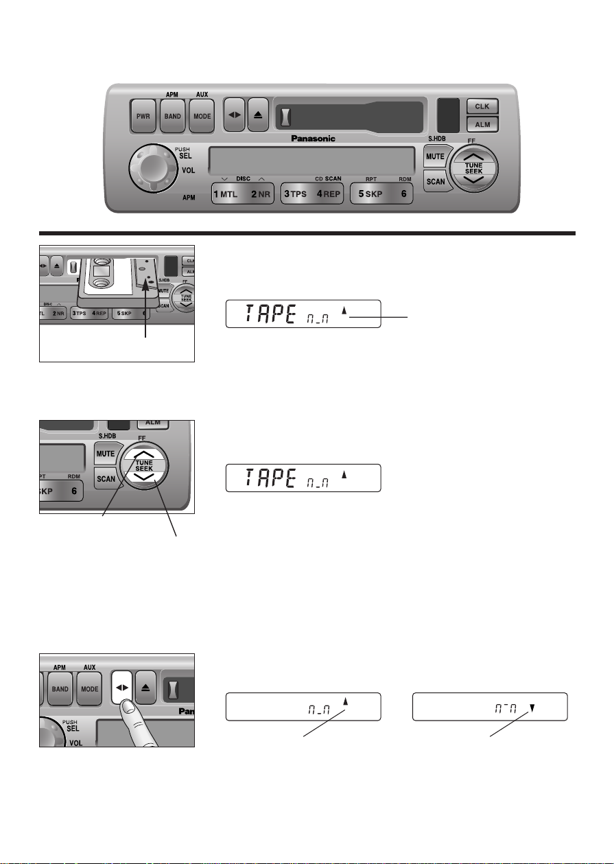
Cassette Tape Player Basics
Playing a Cassette
Insert the cassette with the exposed tape side facing to the right.
Play will start automatically.
Rewind and Fast Forward
Press [ii] (REW) or [jj] (FF) to rewind or fast forward the tape.
Press
[] to stop.
The tape will resume playing from that position.
Changing Sides
Press [] to reverse.
4500U
BASS/FAD
BAL/FADER
FEW
l
k
Exposed Tape side
Playing Side Indicator
Top Side Playing Bottom Side Playing
4500U
FEW
l
k
Rewind
Fast Forward
l
k
FEW
Page 10
10
Cassette Tape Player Basics
(continued)
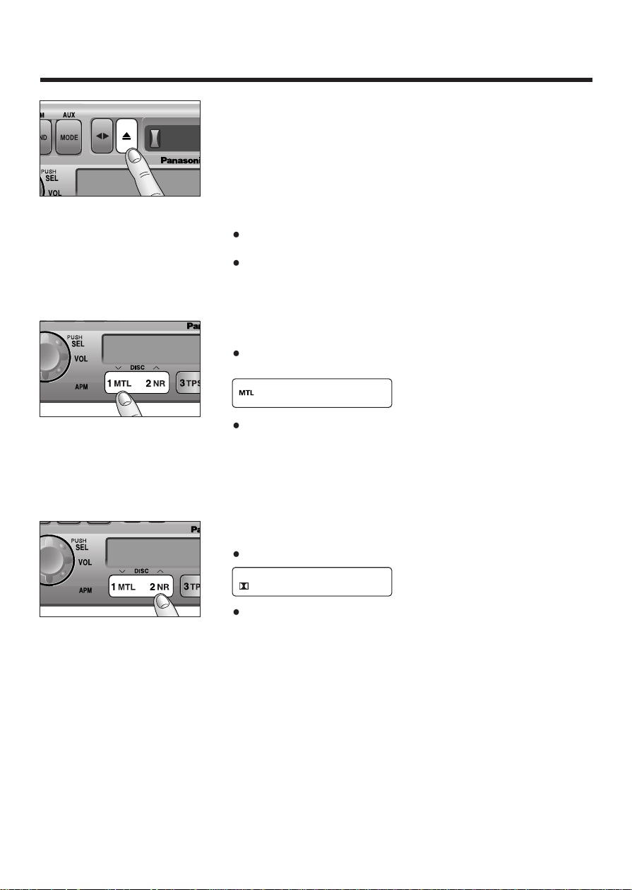
Tape Eject
Press [u] to eject the tape, and the previous mode of operation will
be resumed.
Notes:
Always remove the cassette tape from the unit when the cassette
tape player is not being used.
If power is switched off before [u] is pressed, the cassette will not
be ejected. Switch on the power again and press
[u] to eject the
cassette.
Metal Tape Mode
Press [1 MTL] when playing metal or chromium dioxide (CrO2)
position tapes.
Press [1 MTL] again to cancel.
Note: Playing non-metal position tapes in MTL mode causes high
frequency imbalance, which affects tone quality.
Dolby Noise Reduction
Press [2 NR] to set the Dolby B NR mode.
Press [2 NR] again to cancel.
Note: Set the Dolby B NR mode when playing back a tape recorded
with Dolby B Noise Reduction.
BASS/FAD
BAL/FADER
BASS/FAD
BAL/FADER
Page 11

11
TPS Operation (Tape Program
Search)
Press [3 TPS] to activate the tape program search mode.
To select a desired program, press [ii] or [jj] corresponding
times to go backward (up to 8) or forward (up to 9).
(Rewind:) (Fast forward:)
8019
cc
Ex1. To select the current program
again, press
[3 TPS], and
press
[ii].
Ex2. To select the previous
program, press
[3 TPS], and
press
[ii] twice.
Ex3. To select the next program,
press
[3 TPS] and press [jj].
Ex4. To select the 3rd next
program , press
[3 TPS], and
press
[jj] three times.
Press [3 TPS] again to cancel.
Notes: The TPS mode may not work correctly in the following
cases. This, however, does not mean that the unit is defective.
There is an interval of less than 4 seconds or having a high level
of noise or hum between programs.
There is particularly low-level passage during the program.
Notes:
To maintain your cassette player in top condition, avoid using tapes that are longer than 90
minutes (C-90).
If you insert into the unit a cassette with a loose tape caused by forcing it into cassette with a
finger or the like, the cassette may not be properly reproduced. In such a case, eject the cassette,
make the tape tight, then insert it back into the deck.
d
or
4500U
FEW
l
k
l
k
FEW
4500U
Page 12
12
Cassette Tape Player Basics
(continued)
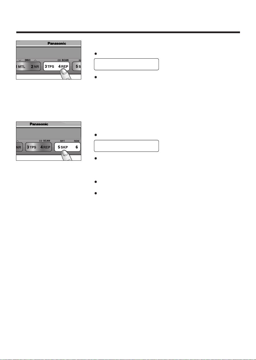
Repeat Play
Press [4 REP] to repeat the current program.
Press [4 REP] again to cancel.
Blank Skip
Press [5 SKP] to skip unrecorded portions on the tape.
Press [5 SKP] again to cancel.
Notes:
When repeat is on, the blank skip does not work because the
repeat has priority over the blank skip.
The blank skip does not work when the unrecorded portion of the
tape is less than 15 seconds.
REPEAT
B•SKIP
Page 13
13
CD Changer Basics
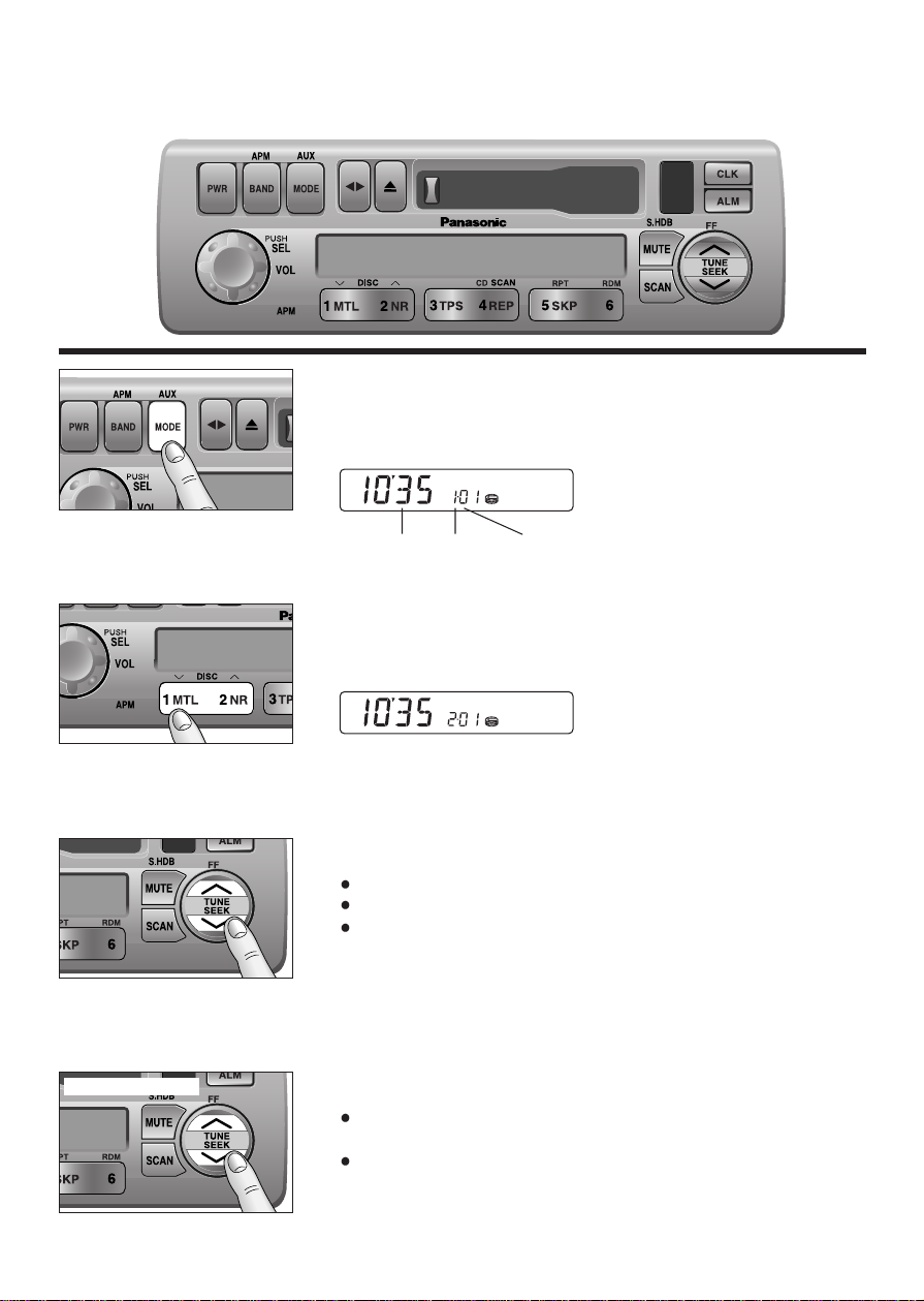
To Start the CD Changer
Once the CD changer has been connected, press [MODE] to
change to the CD changer mode. When a disc magazine is
inserted, CD play starts automatically.
Selecting a Disc
Press [1] (iDISC) or [2] (DISC j) to select a disc in descending
or ascending order.
Then, the selected disc will start to play from the first track.
Note: The number of discs you can load the CD changer with is
specific to each model.
Selecting a Track
Press [jj] to advance to the next track.
Press [ii] to start play from the beginning of the current track.
Press [ii] or [jj] repeatedly to skip the desired number of tracks.
Searching a Track
Press and hold [jj] or [ii] for more than 0.5 seconds to activate
fast forward or reverse.
Release [jj] or [ii] to resume regular CD changer play.
Note: CD changer functions are designed for an optional CD changer unit.
4500U
BASS/FAD
BAL/FADER
FEW
l
k
Hold and release
Play
Time
Disc
Number
Track
Number
BASS/FAD
BAL/FADER
l
FEW
l
FEW
k
4500U
k
4500U
Page 14

0000
E 3E 1
E 2
14
Repeat a Track
Press [5] (RPT: REPEAT) to repeat the current selection.
"REPEAT" indicator lights.
Press [5] (RPT: REPEAT) again to cancel.
Random Selection
Press [6] (RDM: RANDOM). All the available tracks on all discs in
the magazine will be played in a random sequence.
Press [6] (RDM: RANDOM) again to cancel.
Note: The Random mode will stop and the disc select function will
operate once the [1] (
i
DISC) or [2] (DISC j) is pressed.
Scanning Track
Press [4] (CD SCAN). The display blinks and the first 10 seconds
of each track on the discs play in sequence.
Press [4] (CD SCAN) again to cancel.
❏
Error Display Messages
Appears on the display when the
compact disc is dirty or inverted.
Selects the next available compact
disc.
Appears on the display when
compact disc is scratched. Selects
the next available compact disc.
Appears on the display when there
is no disc in the magazine.
Appears on the display when the CD
changer stops operating for some
reason. Please turn off the vehicle
engine (ACC off), discomnect radio
harness for 1 minute then reconnect.
CD Changer Basics
(continued)
REPEAT
RANDOM
Disc
Page 15

15
Clock Basics
(The clock system is 12-hours.)
Initial Time
Press and hold [CLK] to set time display. "AM 12:00" blinks, and
the time setting mode is activated.
Press
[ii] to set the hour.
Press
[jj] to set the minute.
(Hold
[ii] or [jj] to change numbers rapidly.)
Once the time has been set, release [CLK].
Note: When the clock is not set yet, "SET" is displayed.
Resetting the Time
When you want to reset the time, repeat step and above.
Selecting the Clock Display
Press [CLK] to display the current time.
Press
[CLK] again to returns display.
Note: The current time will be displayed at all the time even the
power of the radio is turned off.
4500U
BASS/FAD
BAL/FADER
FEW
l
k
l
d
or
Press and hold
l
l
l
l
Page 16
16
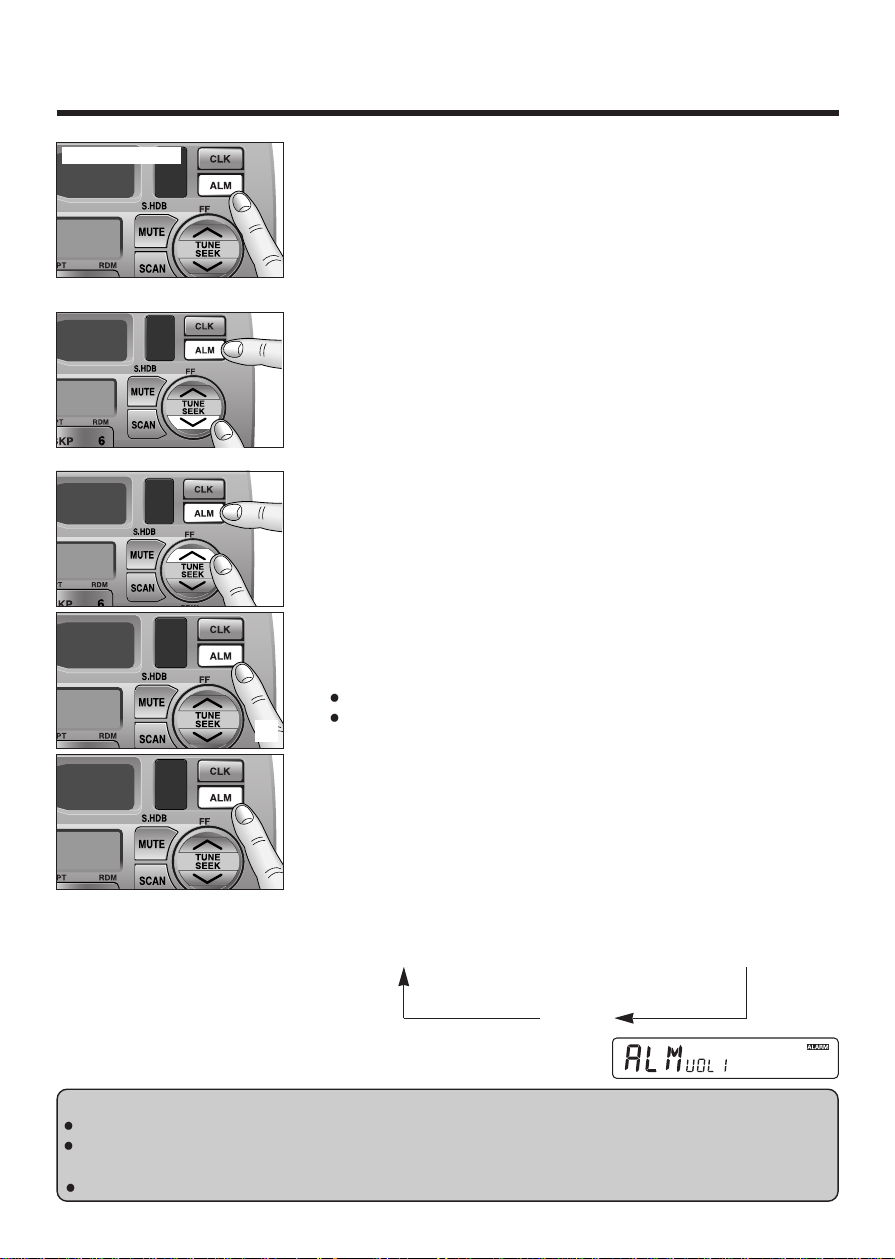
Alarm Time Setting
Press and hold [ALM] to set alarm time Display blinks, and the
alarm time setting mode is activated.
Press
[ii] to set the hour.
Press
[jj] to set the minutes.
(Hold
[ii] or [jj] to change numbers rapidly.)
When you have set the alarm time, release [ALM].
Note: When the alarm is not set yet, "AM 12:00" is displayed.
Resetting the Alarm Time
When you want to reset the alarm time, repeat steps and
above.
Alarm Operation
Alarm is switched to ON or OFF each time [ALM] is pressed.
When the alarm is switched to ON, the alarm will sound at the set
alarm time.
Turning off the Alarm Sound
The alarm will turn off automatically after 90 seconds. Otherwise,
press
[ALM] once.
Alarm output Volume Selection
You can select ALARM VOL 1 (or VOL 2) by pressing [ALM] in
sequence and the display will show as follows.
ALARM TIME
a
ALM VOL 1
a
ALM VOL 2
(display 3 seconds) (display 2 seconds) (display 2 seconds)
OFF
Cautions:
Be careful not to set wrong alarm time, otherwise, the alarm may sound while driving.
If the alarm is set, be sure to check the set alarm time by pressing and holding [ALM] for more than
2 seconds.
If volume is set at "0" level, the output volume will be muted. (Even when ALARM is acting.)
k
d
or
Clock Basics
(continued)
Press and hold
l
l
l
l
l
Page 17

BASS/FAD
BAL/FADER
17
Temperature Reading
(Only for CQ-4500U)
To read the temperatare outside the vehicle, press and hold the
knob
[SEL] for more than 2 seconds. The current temperature in
Fahrenheit is displayed on the display.
Press and release the knob [SEL] to shift the temperature display
to the current operating mode.
Press and hold the knob [SEL] for more then 2 seconds again to
cancel the temperature reading mode.
The display will show "TAPE CLN" to warn you to clean the
cassette head for maintaining its top condition after accumulated
100 hours tape playing.
Press and hold [] for more than 2 seconds to clear the "TAPE
CLN" display and the TAPE mode display will be resumed. (It is
valid only in TAPE mode.)
Notes:
The temperature Sensor Lead must be connected (option).
If you switch the temperature reading mode to the other mode
(EX. Tape mode
CD changer mode), the display will show that
mode for 5 seconds and then resume the temperature reading.
Cassette Head Cleaning Warning
Press and hold
BASS/FAD
BAL/FADER
Press and release
Press and hold
Page 18

18
BASS/FAD
BAL/FADER
l
k
In Case of Malfunction
Reset Switch
If the unit does not respond when the function buttons are
pressed, press the reset switch with a small pointed object,
such as a pencil point. This will restore the unit to its default
settings. All previously stored memory settings will be
erased. Repeat the necessary steps in the previous pages to
reprogram the clock and memory settings. If pressing the
reset switch does not restore normal operation, please
return the radio to the nearest authorized service center for
service.
Page 19

19
Installation Guide
This installation information is designed for experienced installers
and is not intended for non-technical individuals. It does not
contain warnings or cautions of potential dangers in attempting to
install this product.
Any attempt to install this product in a motor vehicle by anyone
other than qualified installer could cause damage to the electrical
system and could result in serious personal injury or death.
WARNING
❏
Overview
This equipment should be installed by a
professional. However, if you plan to install this
unit yourself, your first step is to decide where to
install it. The instructions in these pages will
guide you through the remaining steps:
(Please
refer to "WARNING" statement above)
.
Identify and label the vehicle wires
Connect the vehicle wires to the wires of the
power connector
Install the unit in the dash
Check the operation of the unit
If you do encounter problems, please consult
your nearest authorized dealer.
Caution: This unit will operate with a 12 volt DC
negative ground auto battery system only. Do
not attempt to use it in any other system. Doing
so could cause serious damage.
Before you begin installation, look for the following
items included in the packing with your unit.
Warranty Card ...... Fill this out promptly
Panasonic Servicenter for service Directory
...... Keep this for future reference in case the
unit needs servicing
Installation Hardware ...... Needed for in-dash
installation
❏
Installation Hardware
No.
1
2
2
2
1
1
1
1
2
Item
Mounting Collar
Plain Washer (5 mm
φ
)
Spring Washer (5 mm
φ
)
Hex. Nut (5 mm
φ
)
Rear Support Strap
Hex. Bolt
(5 mm
φ×
25 mm)
Toothed Lock Washer
(5 mm
φ
)
Power Connector
Removal Tool
(U-shaped)
Diagram Qty
1
Antenna Connector
Page 20

20
❏
Required Tools
You'll need a screwdriver, a 1.5 volt AA battery
and the following:
12 V DC ELECTRICAL SIDE-CUT
TEST BULB TAPE PLIERS
❏
Dashboard Specifications
❏
Identify All Leads
The first step in installation is to identify all the
vehicle wires you'll use when hooking up your
sound system.
As you identify each wire, we suggest that you
label it using masking tape and a permanent
marker. This will help avoid confusion when
making connections later.
Note: Do not connect the power connector to the
stereo unit until you have made all connections.
If there are no plastic caps on the stereo hooking
wires, insulate all exposed leads with electrical
tape until you are ready to use them. Identify the
leads in the following order.
Power Lead
If your vehicle has a radio or is pre-wired for one:
Cut the connector wires one at a time from the
plug (leaving the leads as long as possible) so
that you can work with individual leads.
Tur n the ignition on to the accessor y position, and
ground one lead of the test bulb to the chassis.
Touch the other lead of the test bulb to each of
the exposed wires from the cut radio connector
plug. Touch one wire at a time until you find the
outlet that causes the test bulb to light.
Now turn the ignition off and then on. If the bulb
also turns off and on, that outlet is the vehicle
power lead.
If your vehicle is not wired for an audio unit:
Go to the fuse block and find the fuse port for
radio (RADIO), accessory (ACC), or ignition
(IGN).
Battery Lead
If your stereo unit has a yellow lead, you will
need to locate the vehicle's battery lead.
Otherwise you may ignore this procedure. (The
yellow battery lead provides continuous power to
maintain a clock, memory storage or other
function.)
If your vehicle has a radio or is pre-wired for one:
With the ignition and headlights off, identify the
vehicle battery lead by grounding one lead of the
test bulb to the chassis and checking the
remaining exposed wires from the cut radio
connector plug.
If your vehicle is not wired for an audio unit:
Go to the fuse block and find the fuse port for the
battery, usually marked BAT.
Speakers
Identify the vehicle speaker leads. There will be
two leads for each speaker, usually color coded.
THICKNESS
MIN. 3/16" (4.75 mm)
MAX. 7/32" (5.56 mm)
7-5/32" (182mm)
2-3/32" (53 mm)
Page 21

21
Installation Guide
(continued)
A handy way to identify the speaker leads and
the speaker they connect with is to test the leads
using a 1.5 volt AA battery as follows.
Hold one lead against one pole of the battery
and stroke the other lead across the other pole.
You will hear a scraping sound in a speaker if
you are holding a speaker lead.
If not, keep testing different lead combinations
until you have located all the speaker leads.
When you label them, include the speaker
location for each.
Antenna
The antenna lead is a thick, black wire with a
metal plug at the end.
❏
Connect All Leads
Now that you have identified all the wires in the
vehicle, you’re ready to begin connecting them to
the stereo unit wires. The connection diagram on
Page 26, 27 show the proper connections and
color coding of the leads.
We strongly recommend that you test the unit
before making a final installation.
You can set the unit on the floor and make
temporary connections to test the unit. Use
electrical tape to cover all exposed wires.
Important: Connect the red power lead last,
after you have made and insulated all other
connections.
Ground
Connect the black ground lead of the power
connector to the metal vehicle chassis.
Speakers
Connect the speaker wires. See the wiring
diagram below for the proper hookups. Follow
the diagram carefully to avoid damaging the
speakers and the stereo unit.
The speaker used must be able to handle more
than 37 watts of audio power. If using an
optional audio power, the speakers should be
able to handle the maximum amplifier output
power. Speakers with low input ratings can be
damaged.
Speaker impedance should measure 4 - 8 ohms,
which is typically marked on most speakers.
Lower or higher impedance speakers will affect
output and can cause both speaker and stereo
unit damage.
Caution: Never ground the speaker cords. For
example, do not use a chassis ground system or
a three-wire speaker common system. Each
speaker must be connected separately using
parallel insulated wires. If in doubt about how
your car's speakers are wired, please consult
with your nearest professional installer.
L
R
+
–
+
–
L
R
+
–
+
–
L
R
+
–
+
–
CORRECT
No Common Ground
INCORRECT
Common Chassis Ground
INCORRECT
Speaker Common
(common earth lead)
Page 22

22
Battery
Connect the yellow battery lead to the correct
radio wire or to the battery fuse port on the fuse
block.
Antenna
Connect the antenna by plugging the antenna
lead into the antenna receptacle.
Equipment
Connect any optional equipment such as
amplifier, according to the instructions furnished
with the equipment. Keep about 12 inches (30
cm) of distance between the speaker
cords/amplifier unit and the antenna/antenna
extension cord. Read the operating and
installation instructions for any equipment you
will connect to this unit.
Accessory (ACC) Power
Connect the red power lead to the correct
vehicle radio wire or to the appropriate fuse port
on the fuse block.
If the stereo unit functions properly with all these
connections made, disconnect the wires and
proceed to the final installation.
❏
Final Installation
Lead Connections
Connect all wires, making sure that each
connection is insulated and secure. Bundle all
loose wires and fasten them with tape so they
won't fall down later. Now insert the stereo unit
into the mounting collar.
Congratulations! After making a few final checks,
you're ready to enjoy your new auto stereo
system.
❏
Final Checks
1. Make sure that all wires are properly
connected and insulated.
2. Make sure that the stereo unit is securely
held in the mounting collar.
3. Turn on the ignition to check the unit for
proper operation.
If you have difficulties, consult your nearest
authorized professional installer for assistance.
Page 23

23
Installation Guide
(continued)
❏
Installation Procedures
Note: Disconnect the cable from the negative (–) battery terminal.
1
Mounting Collar
Dashboard
Mounting Tab
Screwdriver
2. Securre the rear of the unit.
a) Insert Power Connector to the unit.
b) Check the electrical connection by referring to this operating instructions.
c) Insert the unit into Mounting Collar
and push it in until "click" is heard.
Unit
d) Secure the rear of the unit to the vehicle by either of the two recommended methods on the next
page.
Power Connector8
1. Secure the Mounting Collar .
Insert Mounting Collar into the vehicle's dashboard, and bend mounting tabs out with a
screwdriver.
When bending the mounting tab of the mounting collar with a screwdriver, be careful not to injure
your hands and fingers.
We strongly recommend you to wear gloves for installation work to protect yourself from injuries.
Page 24

24
■
Using the Rear Support Strap
■
Using the Rubber Cushion (option)
(If there is an existing Rear Support Bracket on the fire wall of the vehicle.)
Cover Mounting Bolt on the rear of the unit with Rubber Cushion (option), and mount it into the
existing Rear Support Bracket.
Rubber Cushion (option)
Mounting Bolt
Mounting Collar
Rear Support Bracket
(existing on the vehicle)
3. After installation reconnect the negative (–) battery terminal.
Page 25

25
Installation Guide
(continued)
To Remove the Unit from the vehicle's dashboard
Insert each Removal Tool and pull.
Note: Do not lose Removal Tool. They will be needed to remove the unit from the vehicle's
dashboard.
Removal Tool
(U-shaped)
Page 26

26
(Only for CQ-4500U)
Cautions:
This product is designed to operate with a 12-volt negative ground battery system.
To prevent damage to the unit, be sure to follow the connection diagram below.
Remove the covering of the leads approx. 5 mm long from their end before connecting.
Do not insert the power connector into the unit until the wiring is completed.
Be sure to insulate any exposed wires from a possible short-circuit from the vehicle chassis. Bundle
all cables and keep cable terminals free from touching any metal parts.
Electrical Connections
Temperature Sensor Lead
Cassette Receiver
CQ-4500U
Sleeper Room Remote Connector
(Connect to CA-RC300U)
Antenna
To AUX
(L)
(R)
Preamp-Out
(L)
(White
w/black
stripe)
(Rear Side)
Antenna Connector
(Red)(R)
(White)
(Red)
(White)
AUX-IN
PRE-OUT
(Rear)
CD Changer Control Connector
Power Connector
Amp. Cont(MAX 0.1A)
ACC
Ground
Battery
AUX-In Sensor
Steering remote
(Violet w/black stripe)(Gray w/black stripe)
(Gray)(white)
(Green
w/black
stripe)
(Green)
(Blue)
(Red)
(Black)
(Yellow)
Fuse(10A)
(Orange w/white
(Orange)
stripe)
Accessory Power(ACC)
(+12V DC, negative ground
only)
Ground Lead
(Connect to a clean, bare
metallic part of your vehicle)
Battery Lead
(Connect to vehicle battery)
AUX-In Sensor Lead
(Connect to vehicle computer)
Steering remote control lead
(Violet)
Left Speaker
(Front)
Right Speaker
(Front)
Left Speaker
(Rear)
Right Speaker
(Rear)
Page 27

27
(Only for CQ-4300U)
Cautions:
This product is designed to operate with a 12-volt negative ground battery system.
To prevent damage to the unit, be sure to follow the connection diagram below.
Remove the covering of the leads approx. 5 mm long from their end before connecting.
Do not insert the power connector into the unit until the wiring is completed.
Be sure to insulate any exposed wires from a possible short-circuit from the vehicle chassis. Bundle
all cables and keep cable terminals free from touching any metal parts.
Electrical Connections
(continued)
CD Changer Control Connector
Cassette Receiver
CQ-4300U
Antenna
Antenna Connector
(White
w/black
stripe)
(Rear Side)
(Gray)(white)
Power Connector
ACC
Ground
Battery
(Green
w/black
stripe)
(Green)
Fuse(10A)
(Violet w/black stripe)(Gray w/black stripe)
(Red)
(Black)
(Yellow)
Accessory Power(ACC)
(+12V DC, negative ground
only)
Ground Lead
(Connect to a clean, bare
metallic part of your vehicle)
Battery Lead
(Connect to vehicle battery)
(Violet)
Left Speaker
(Front)
Right Speaker
(Front)
Left Speaker
(Rear)
Right Speaker
(Rear)
Page 28

28
Troubleshooting
❏
Maintenance
Your product is designed and manufactured
to ensure a minimum of maintenance. Use a
soft cloth for routine exterior cleaning. Never
use benzine, thinner, or other solvent.
❏
When Something Doesn't Work
Check the charts on page 29 for possible
causes and solutions to any problem you
might be experiencing. Some simple checks
or minor adjustments may eliminate the
problem.
❏
Product Servicing
If the suggestions in the charts don't solve
the problem, we recommend that you take it
to your nearest authorized dealer. Panasonic
Servicenter. The unit should be serviced
only by a qualified technician.
❏
Replacing the Fuse
Use fuses of the same specified rating (10
amps). Using different substitutes or fuses
with higher ratings, or connecting the unit
directly without a fuse, could cause fire or
damage to the stereo unit.
If the replacement fuse fails, contact your
nearest Panasonic Servicenter for
service.
❏
Notes on Cassette Tapes
Tape Slack:
Use a pencil or similar object to take up the
slack as shown. If a loose tape is used, this may
result in the tape becoming tangled in the
rotating parts of the unit.
Label
Pencil
Do not touch
or pull out the tape.
Page 29

29
Troubleshooting
(continued)
❏
Troubleshooting Tips
PROBLEM
Unit does not turn on.
Radio has static.
Radio memory buttons do not
work.
Tape sound quality is poor.
Inverted Sound (Left/Right
Connections.)
No sound from front or rear
speakers
POSSIBLE CAUSE
Dead vehicle battery
Ignition or ACC is not on.
Bad power line connection
Fuse is blown.
Antenna not hooked up
Close to high power lines
Not holding buttons down long
enough
Heads are dirty.
Poor quality tape.
The speaker cords are inverted.
The fader control is set on the
wrong position.
PROBABLE SOLUTION
Charge vehicle battery.
Turn ignition to On or ACC.
Check connections.
Replace fuse.(consult your dealer)
Hook up antenna.
Move away from high power lines.
Press and hold buttons for more
than 2 seconds.
Clean heads. (Ask a service
representative for advice.)
Use better quality tape.
Check the speaker cords.
Adjust the fader control of the
unit correctly.
Page 30

30
Specifications
General
Power Supply : 12 V DC (11V-16V) Test Voltage 14.4V, Negative ground
Maximum Power Output : 37 W
×
4 channels at 400 Hz, Volume Control maximum
Power Output : 18 W per channel into 4 ohms, 40 to 30,000Hz at 3% THD.
Tone Action : Bass; ± 12 dB at 100 Hz
Treble; ± 12 dB at 10 kHz
Current Consumption : Less than 2.5 A (tape mode, 0.5 W 4-speaker)
Speaker Impedance : 4 Ω (4-8 Ω acceptable)
Dimensions (W
×H ×
D) : 7" ×1-15/16" ×5-7/8" (178 ×50 ×150 mm)
Weight : 3 lbs. (1.4 k
)
AM Radio
Frequency Range : 530-1,710 kHz
Useable Sensitivity : 28 dB/µV (25 µV/ S/N 20 dB)
FM Stereo Radio
Frequency Range : 87.9-107.9 MHz
Useable Sensitivity : 12 dBf. (1.1 µV / 75Ω, S/N 30 dB)
50 dB Quienting Sensitivity : 17 dBf. (1.8 µV / 75Ω)
Frequency Response : 30-15,000 Hz ± 3 dB
Alternate Channel Selectivity : 75 dB
Stereo Separation : 35 dB at 1,000 Hz
Signal/Noise Ratio : 70 dB (Mono)
Weather Band Radio
Frequency Range : 162.40-162.55 MHz
Useable Sensitivity : 3 dB/µV (S/N 20 dB)
Signal/Noise Ratio (40 dB/µV) : 50 dB
Tape Player
Reproduction System : 4-track, 2-program stereo
Tape Speed : 1-7/8"/sec (4.76 cm/sec)
FF/REW Time : Less than 110 SEC (C-60)
Frequency Response : 35 - 14,000 Hz ± 3 dB
Wow and Flutter : 0.09% (WRMS)
Signal/Noise Ratio : 52 dB (Dolby NR on: 62 dB)
*Above specifications comply with EIA standards.
Note: Specifications and design are subject to modification without notice due to improvements in
technology.
Dobly noise reduction manufactured under license from Dolby Laboratories Licensing Corporation.
"DOLBY" and the double-D symbol
A
are trademarks of Dolby Laboratories Licensing Corporation.
This unit has been manufactured under the Part 15 of the FCC Rules.
Do not attempt to make any changes or modifications to this unit.
Part 15 of the FCC Rules
Page 31

Page 32

Panasonic Consumer Electronics
Company, Division of Matsushita
Electric Corporation of America
One Panasonic Way, Secaucus,
New Jersey 07094
YFM284C331ZA TAMACO0200-0 Printed in Taiwan
 Loading...