

Page 1
Operating
VOLUME
SLOT 1
A
B
DEGAUSS
MENU
BLUE
CHECK
ASPECT
AREA
MARKER
UNDER
SCAN
PULSE
CROSS
COLOR
OFF
SLOT 2
C
D
SLOT 3
POWER
E
F
INPUT SELECT
MUTING
Instructions
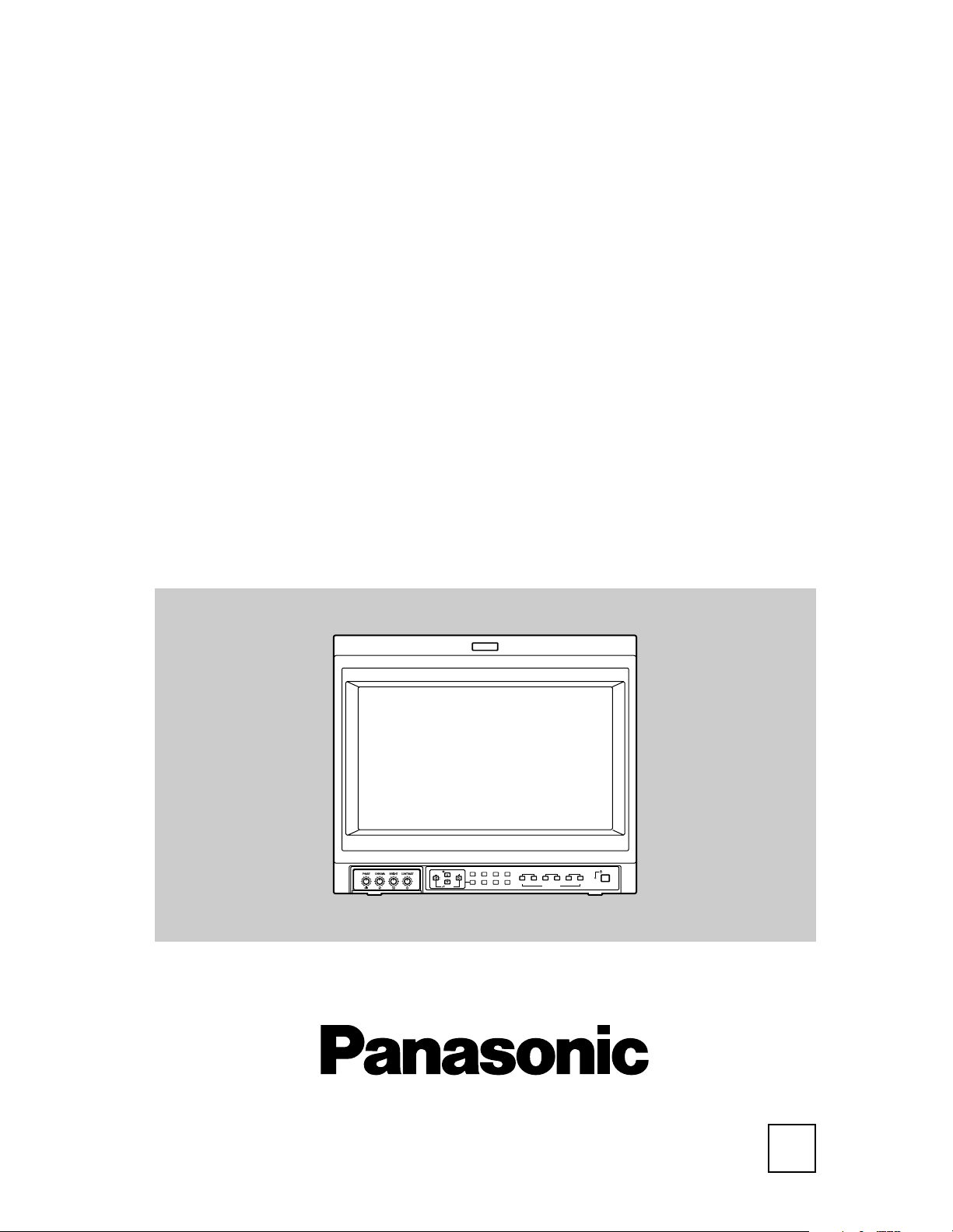
Multi-Format Monitor
Model BT-H1700BP
Before attempting to connect, operate or adjust this product, please read these instructions
completely.
Printed in Japan
VQT0G67-1
LCT1464-001B
1003-MK-MW-VP
P
Page 2
SAFETY PRECAUTIONS
In order to prevent any fatal accidents caused by misoperation
or mishandling the monitor, be fully aware of all the following
precautions.
WARNINGS
To prevent fire or shock hazard, do not expose this
monitor to rain or moisture. Dangerous high voltages are
present inside the unit. Do not remove the back cover of
the cabinet. When servicing the monitor, consult qualified
service personnel. Never try to service it yourself.
WARNING : THIS APPARATUS MUST
BE EARTHED.
Improper operations, in particular alternation of high
voltage or changing the type of tube may result in x-ray
emission of considerable dose. A unit altered in such a
way no longer meets the standards of certification, and
must therefore no longer be operated.
This monitor is equipped with a 3-blade grounding-type
plug to satisfy FCC rule. If you are unable to insert the
plug into the outlet, contact your electrician.
FCC INFORMATION (U.S.A. only)
CAUTION: Changes or modification not approved by
PANASONIC could void the user’s authority to operate
the equipment.
NOTE: This equipment has been tested and found to
comply with the limits for a Class A digital device,
pursuant to Part 15 of the FCC Rules. These limits are
designed to provide reasonable protection against
harmful interference when the equipment is operated in a
commercial environment. This equipment generates,
uses, and can radiate radio frequency energy and, if not
installed and used in accordance with the instruction
manual, may cause harmful interference to radio
communications. Operation of this equipment in a
residential area is likely to cause harmful interference in
which case the user will be required to correct the
interference at his own expense.
Notice (U.S.A. only)
This product utilizes both a Cathode Ray Tube (CRT) and
other components that contain lead. Disposal of these
materials may be regulated in your community due to
environmental considerations. For disposal or recycling
information please contact your local authorities, or the
Electronics Industries Alliance: <http://
www.eiae.org.>
䡵 PRECAUTIONS
• Use only the power source specified on the unit.
(120 V AC, 50 Hz/60 Hz)
• Keep flammable material, water, and metal objects away from
the unit – especially the interior of the unit.
• This unit incorporates high voltage circuitry.
For your own safety and that of your equipment, do not
attempt to modify or disassemble this monitor.
There are no user-serviceable parts inside.
• Video or audio signals cannot be input to this monitor without
optional input cards.
• In these instructions, all explanations (except where noted)
refer to the BT-H1700B with input cards installed.
SCREEN BURN
• It is not recommended to keep a certain still image
displayed on screen for a long time as well as displaying
extremely bright images on screen. This may cause a burning
(sticking) phenomenon on the screen of cathode-ray tube. This
problem does not occur as far as displaying normal video
playback motion images.
䡵 HANDLING
• Avoid shocks or vibrations. These may damage the unit and
cause it to malfunction.
• Do not block the ventilation slots.
• Do not expose this unit to high temperatures.
Extended exposure to direct sunlight or a heater could deform
the cabinet or cause the performance of internal components
to deteriorate.
• Do not place the unit near appliances generating strong
electric or magnetic fields. There can generate picture noise
and instability.
• Keep the monitor clean by wiping the cabinet and CRT screen
with a piece of soft cloth. Do not apply thinner or benzine.
These chemicals can damage the finish and erase printed
letters. When the unit is excessively dirty, use a diluted neutral
cleanser, then wipe away the cleanser with a dry cloth.
DEGAUSS
• Do not use a magnet eraser to degauss the monitor’s cathode
ray tube from the outside. Doing so may distort its aperture
grill and cause a malfunction.
2
Page 3

CONTENTS
SAFETY PRECAUTIONS ........................................................................... 2
CONTROLS AND FEATURES.................................................................... 4
CONTROLS AND FEATURES
(INPUT CARD: OPTIONAL) ..................................................................... 7
PREPARATION ........................................................................................... 9
BASIC MENU OPERATIONS
(MAIN MENU, SET-UP MENU) ............................................................... 11
HOW TO USE “MAIN MENU” ................................................................... 13
HOW TO USE “SET-UP MENU” ............................................................... 16
HOW TO USE EXTERNAL CONTROL ..................................................... 21
TROUBLESHOOTING .............................................................................. 23
SELF-CHECK INDICATIONS ................................................................. 25
SPECIFICATIONS ..................................................................................... 26
3
Page 4

VOLUME
SLOT 1
A
B
DEGAUSS
MENU
SCREENS
CHECK
ASPECT
AREA
MARKER
UNDER
SCAN
PULSE
CROSS
COLOR
OFF
SLOT 2
C
D
SLOT 3
POWER
E
F
INPUT SELECT
2 3 4 5 8 11 12 13 14
1096 6 15 16 17
18
19
20
MUTING
7
VOLUME
SLOT 1
A
B
DEGAUSS
MENU
BLUE
CHECK
ASPECT
AREA
MARKER
UNDER
SCAN
PULSE
CROSS
COLOR
OFF
SLOT 2
C
D
SLOT 3
POWER
E
F
INPUT SELECT
1
CONTROLS AND FEATURES
FRONT VIEW
<Front Panel>
1
Tally lamp
Lights when the tally control signal is ON.
• Set the MAKE/TRIGGER terminal’s tally control in the
REMOTE (external control) terminal setup menu.
The lamp color can be set to red or green.
• To set the color, use TALLY SELECT in the “FUNCTION
SETTING” setup menu or MAKE/TRIGGER in the
REMOTE (external control) terminal setup menu.
For details, refer to pages 17 and 21.
PHASE adjustment knob
2
Adjusts picture hue.
• Turn the knob to the left to make the picture redder, and
turn it to the right to make the picture greener.
3
CHROMA adjustment knob
Adjusts picture color density.
• Turn the knob to the left to make the picture color lighter,
and turn it to the right to make the picture color deeper.
4
BRIGHT adjustment knob
Adjusts picture brightness.
• Turn the knob to the left to make the picture darker, and
turn it to the right to make the picture brighter.
CONTRAST adjustment knob
5
Adjusts picture contrast.
• Turn the knob to the left to make the picture contrast lower,
and turn it to the right to make the picture contrast higher.
6
VOLUME buttons
Adjusts the speaker volume.
• Pressing this button displays the VOLUME level bar on
the screen. Pressing the button again allows you to adjust
speaker volume.
MUTING button
7
Pressing this button mutes the output sound.
• To cancel “MUTING ON” (no sound), press MUTING
button again, or press the VOLUME “–” or “+” buttons.
NOTE:
When a menu or setting item (such as MAIN MENU, SET-UP
MENU, sub-menu, or VOLUME bar) is displayed on the screen,
this button functions as a control button for the menu screen. In
this case, it will not mute the sound when pressed.
8
EMBEDDED AUDIO channel switch button
Press this button while the VOLUME bar is displayed
on the screen to change the input sound channel.
• When the button is pressed, the next highest channel
is selected.
• When the button is pressed, the next lowest channel is
selected.
NOTES:
Switchable channels correspond with the group selected in the
“E.AUDIO GROUP” of the “FUNCTION SETTING” setup menu.
* Valid when an input card compliant with EMBEDDED AUDIO is
installed.
9
Menu select buttons
Selects menu screen items or set-up menu screen.
MENU button
10
Displays, adjusts or closes a menu screen.
11
DEGAUSS button/lamp
Press the DEGAUSS button. The button lights
and degaussing is performed automatically.
• When the degaussing is completed, the light goes off.
12
UNDER SCAN button/lamp
Press the UNDER SCAN button. The button
lights and the screen is reduced (under-scan)
and the whole screen is displayed.
• When the UNDER SCAN button is pressed while lit, the light
goes off and the screen returns to normal size (over-scan).
• Use this function to check the whole screen.
NOTE:
This function is invalid with the RGB-input screen.
PULSE CROSS button/lamp
13
When you press the PULSE CROSS button, the
button lights and the picture moves horizontally
and vertically. The synchronized signal is
displayed and the screen automatically
brightens to make it easier to confirm the
synchronized sections.
• When the PULSE CROSS button is pressed while lit, the
light goes off and the normal screen is restored.
NOTE:
This function is invalid with the RGB-input screen.
4
Page 5
COLOR OFF button/lamp
14
When you press the COLOR OFF button, the
button lights and the screen becomes
monochrome. Only the brightness signal is
displayed.
• When the COLOR OFF button is pressed while lit, the
light goes off and the normal screen is restored.
• Use this function to confirm the noise in the brightness
signal or to confirm the white balance.
NOTE:
This function is invalid with the RGB-input screen.
SCREENS CHECK button/lamp
15
Press the SCREENS CHECK button. The button
lights and the screen changes in the following order:
• Press the SCREENS CHECK button when the blue
screen is displayed. The light goes off and the normal
screen is restored.
• Use this function to confirm or adjust CHROMA or
PHASE.
NOTE:
This function is invalid with the RGB-input screen.
16
ASPECT button/lamp
When the ASPECT button is pressed while the
screen ratio is 4:3, the button lights and the
screen ratio changes to 16:9.
• When the ASPECT button is pressed while lit, the light
goes off and the normal screen is restored.
NOTE:
This function is invalid with the RGB-input screen.
AREA MARKER button/lamp
17
This button turns the AREA MARKER function
ON/OFF.
• AREA MARKER function includes MARKER SELECT,
ZOOM, and SAFETY MARKER functions. Refer to “AREA
MARKER” on page 14 for more information.
• When AREA MARKER is set to ON, the button lights.
NOTES:
• Functions do not operate when they are set to OFF in the “AREA
MARKER”.
• Initial setting of each function in the “AREA MARKER” Menu is
OFF. Before you can use the AREA MARKER function, you must
change the “AREA MARKER” Menu settings first. Refer to “AREA
MARKER” on page 14 for details.
• This button does not operate when RGB is input.
• The ZOOM function does not operate in the under-scan mode.
INPUT SELECT button/lamp
18
Selects an input signal from one of the input
cards installed in the monitor’s card slots
(SLOT1 – SLOT3).
Select SLOT1: press A or B
Select SLOT2: press C or D
Select SLOT3: press E or F
Refer to the input card instructions on pages 7 and 8 for
details on the correspondence between the input terminals
and the INPUT SELECT buttons.
• The INPUT SELECT button corresponding to the current
input signal lights.
• When the input is switched, the new input status is
displayed on the screen for about 3 seconds.
• To display the current input status again, press the
illuminated INPUT SELECT.
䡵 About status display
Displays information on the current input selection and the
monitor settings.
INPUT C ........ Selected input
VIDEO ........... Input card status (*1)
NTSC ............ Signal format (*2)
HIGH ............. Setting of “COLOR TEMP.” (*3)
EXT SYNC .... External synchronization (*4)
*1 Notes
• “NO SLOT” is displayed when there is no input card inserted in
the slot corresponding to the selected input.
• “COMPO.” or “RGB” is displayed when a component or RGB
signal (input from COMPONENT/RGB INPUT CARD) is
selected.
• “VIDEO(Y/C)” is displayed when S-video is input from VIDEO 2
(INPUT SELECT B/D/F).
*2 Notes
• “NO SYNC” is displayed when no video signal is input.
• When “SYNC SELECT” is set as “EXT.” (external), “NO SYNC” is
displayed even when a video signal is input and a synchronized
signal is not input. Refer to “SYNC SELECT” on page 17 for more
information.
*3 Note
Refer to “COLOR TEMP.” on page 18 for details on “COLOR TEMP.”
settings.
*4 Note
When “SYNC SELECT” is set to “INT.” (internal synchronization),
no message is displayed. Refer to “SYNC SELECT” on page 17 for
more information.
5
Page 6
REAR/SIDE VIEW
MAKE
SLOT1
RS-232C
REMOTE
SLOT2
SLOT3
MAIN POWER
<Rear Panel> <Side Panel>
REMOTE (external control) terminals
Terminals for controlling the monitor from an
external unit.
MAKE/TRIGGER terminal (Upper):
Enables the monitor to be controlled by closing the circuit
(point of contact) connected to the terminal.
RS-232C terminal (Lower):
Enables the monitor to be controlled from a personal
computer via a serial communication.
Input card slots (SLOT 1 – SLOT 3)
Optional input cards can be installed in these
slots. Input cards are not provided when you
purchase the monitor.
NOTE:
It is not possible to input video or audio signals to the monitor
when no input cards are installed.
MAIN POWER switch
Press the switch to turn the main power ON or
OFF. When the main power is ON, the power
lamp on the front panel lights in yellow and the
monitor enters the stand-by mode.
• I : ON 䡬 : OFF
6
Page 7

CONTROLS AND FEATURES
VIDEO 1
OUT
IN
AUDIO 2
AUDIO 1
OUT
IN
VIDEO 2
OUT
Y/C IN
IN
OUT
IN
EXT.SYNC
1
2
3
4
5
B/PB/B-Y
G/Y
OUTIN
OUTIN
R/PR/R-Y
OUTIN
VD
OUTIN
HD/C
S
OUTIN
OUTIN
AUDIO
OUT
IN
1
2
3
4
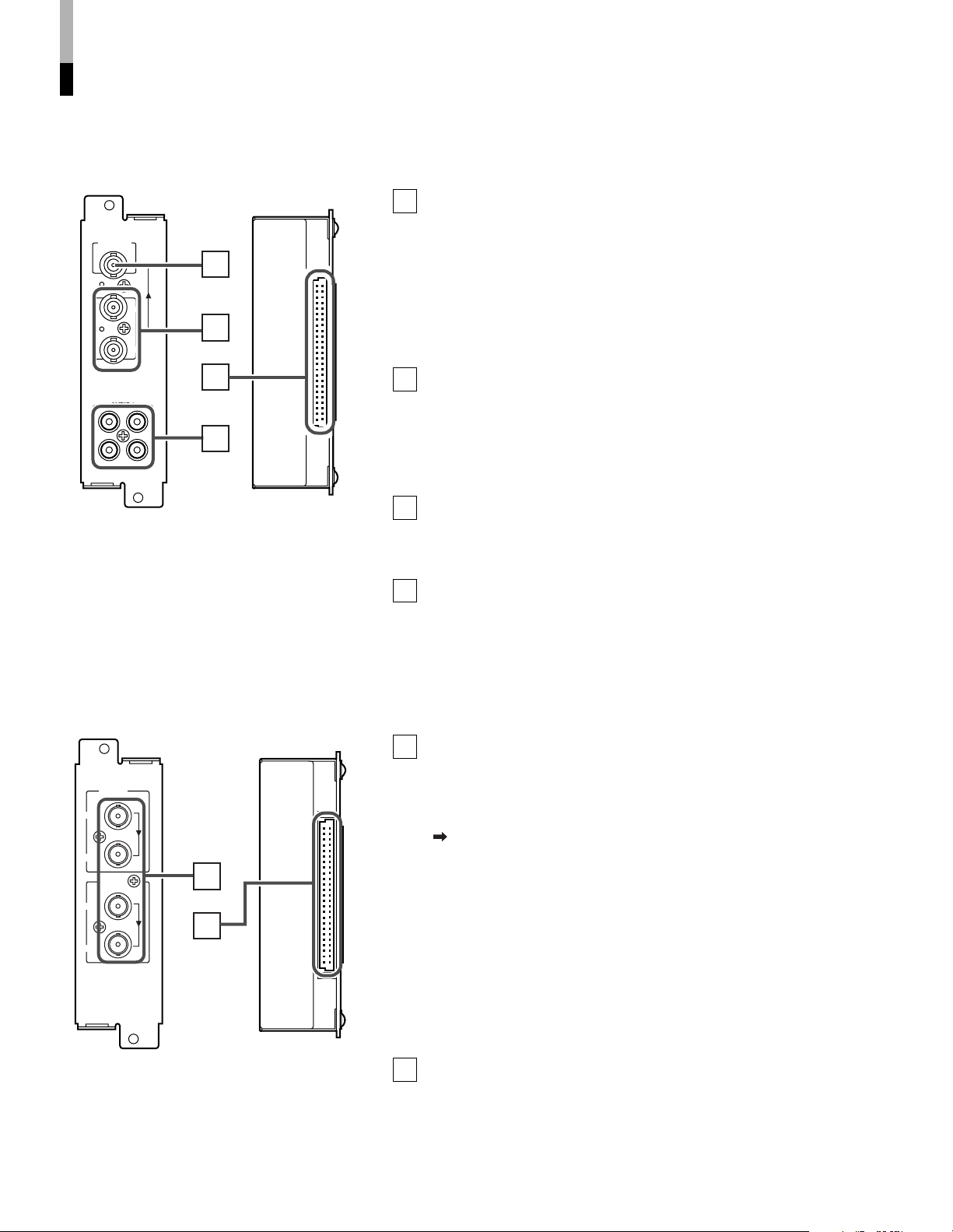
(INPUT CARD: OPTIONAL)
7 VIDEO INPUT CARD (BT-YA701P)
1
Composite signal input/output terminals (VIDEO 1, VIDEO 2)
Input (IN) and output (OUT) terminals for the composite video signals of
the NTSC, PAL, and black/white (50 Hz/60 Hz).
NTSC and PAL are switched in the “COLOR SYSTEM”. Refer to “COLOR
SYSTEM” on page 17.
Select VIDEO 1: press INPUT SELECT A (SLOT1)/C (SLOT2)/E (SLOT3) buttons.
Select VIDEO 2: press INPUT SELECT B (SLOT1)/D (SLOT2)/F (SLOT3) buttons.
* The IN and OUT terminals are bridge-connected (auto termination).
2
S-video signal input terminal (only for VIDEO 2)
Input terminal for the S-video signal.
• When an S-video signal is input to this terminal and a video signal is input to
VIDEO 2, the S-video signal has priority over the video signal.
3
Synchronized signal input/output terminals (for both
VIDEO 1 and VIDEO 2)
Input (IN) and output (OUT) terminals for the complex synchronized signals.
To use these terminals, set “SYNC SELECT” to “EXT.” Refer to “SYNC
SELECT” on page 17 for more information.
7 Compatible signal formats:
NTSC (3.58 MHz), PAL (4.43 MHz), blackand-white (50 Hz/60 Hz)
NOTES:
• When an external synchronized signal is input, external synchronization is
prioritized for both VIDEO 1 and VIDEO 2.
• External synchronization does not function when a video signal (except black burst
signal) is included in the complex synchronized signal.
Audio signal input/output terminals (for both VIDEO 1
4
and VIDEO 2)
Input (IN) and output (OUT) terminals for analog audio signals
corresponding to VIDEO 1 and VIDEO 2.
• The IN and OUT terminals are bridge-connected.
Connection terminal
5
Attach to the connection terminal of your Multi-Format Monitor.
7 COMPONENT/RGB INPUT CARD (BT-YA702P)
1
Component/RGB signal input/output terminals
Input (IN) and output (OUT) terminals for component (color difference) or
RGB signals.
Select component signal: INPUT SELECT A (SLOT1)/C (SLOT2)/E (SLOT3)
Select RGB signal : INPUT SELECT B (SLOT1)/D (SLOT2)/F (SLOT3)
* The IN and OUT terminals are bridge-connected (auto termination).
2
Synchronized signal input/output terminals
Input (IN) and output (OUT) terminals for the vertical, horizontal or complex
synchronized signals.
䡵 Compatible signal formats:
480/60i, 576/50i, 576/50p, 480/60p, 720/50p,
720/60p, 1035/60i, 1080/50i, 1080/60i,
1080/24psF
• To use these terminals, set “SYNC SELECT” to “EXT.”
Refer to “SYNC SELECT” on page 17 for more information.
Audio input/output terminals
3
Input (IN) and output (OUT) terminals for the analog audio signals.
• The IN and OUT terminals are bridge-connected.
Connection terminal
4
Attach to the connection terminal of your Multi-Format Monitor.
7
Page 8
AUDIO 2
AUDIO 1
OUT
IN
SWITCHED
OUT
SDI 1
SDI 2
IN
IN
1
2
3
4
E.AUDIO
HD SDI 1
IN
OUT
2
1
E.AUDIO
HD SDI 2
IN
OUT
CONTROLS AND FEATURES
(INPUT CARD: OPTIONAL) (cont’d)
7 SDI INPUT CARD (BT-YA703P)
SWITCHED OUT terminal
1
Output (OUT) terminal for the re-clocked signal. The input signal from
SDI 1 or SDI 2 (selected with the INPUT SELECT buttons) is re-clocked
and output from this terminal.
NOTES:
• Even when the input signal is switched from the SDI Input Card, the SWITCHED
OUT terminal still outputs the SDI 1 or SDI 2 re-clocked signal (whichever you
selected last).
• No signal is output from the SWITCHED OUT terminal when the monitor is turned
off or in the stand-by mode.
D1 SDI signal input terminal (SDI 1, SDI 2)
2
Accepts an SMPTE259M compliant D1 SDI signal (component serial
digital signal).
Select SDI 1 input: press INPUT SELECT A (SLOT1)/C (SLOT2)/E (SLOT3) buttons.
Select SDI 2 input: press INPUT SELECT B (SLOT1)/D (SLOT2)/F (SLOT3) buttons.
NOTE:
Not compliant with EMBEDDED AUDIO.
Audio signal input/output terminals (for both SDI 1 and
3
7 Compatible signal formats:
480/60i, 576/50i
SDI 2)
Input (IN) and output (OUT) terminals for the analog audio signals.
• The IN and OUT terminals are bridge-connected.
Connection terminal
4
Attach to the connection terminal of your Multi-Format Monitor.
7 HD SDI INPUT CARD (BT-YA705G)
Compliant with EMBEDDED AUDIO
HD SDI signal input/output terminals (HD SDI 1, HD SDI 2)
1
Input (IN) and output (OUT) terminals for the HD SDI signal (HD
component serial digital signal).
This card is also compatible with EMBEDDED AUDIO signals with a 48
kHz sampling frequency and channel range of 1 to 8 channels.
The EMBEDDED AUDIO output channel is controlled from this monitor.
Refer to “EMBEDDED AUDIO channel switch button” on page 4 for more
information.
Select HD SDI 1 input: press INPUT SELECT A (SLOT1)/C (SLOT2)/E (SLOT3)
Select HD SDI 2 input: press INPUT SELECT B (SLOT1)/D (SLOT2)/F (SLOT3)
7 Compatible signal formats:
720/50p, 720/60p, 1080/50i, 1080/60i,
1035/60i, 1080/24psF, EMBEDDED AUDIO
OUT terminal
The re-clocked HD SDI 1 and/or HD SDI 2 input signal is output from the
HD SDI 1 OUT and/or HD SDI 2 OUT terminal.
NOTE:
Signals cannot be output from the OUT terminal when the monitor’s power is OFF or
in the stand-by mode.
2
Connection terminal
Attach to the connection terminal of your Multi-Format Monitor.
buttons.
buttons.
8
Page 9
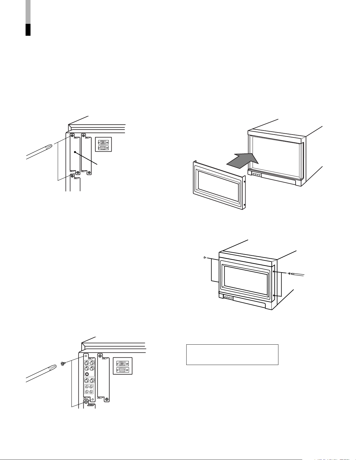
PREPARATION
䡵 INSTALLING THE INPUT CARD
Optional input cards are necessary to use the functions of this
monitor. Before mounting the monitor or connecting other
equipment to the monitor, be sure to install the input cards.
1. Turn off the Multi-Format Monitor’s main power
and unplug the power cable from the AC outlet.
2. Unscrew the screws and remove the slot cover
from the slot (on the rear side of the monitor) in
which you are going to install the card.
Slot cover
Rear side of the BT-H1700B
Multi-Format Monitor
3. Insert the Input Card’s board (green-colored)
into the slot, fitting the board into the guide rails
on the top and bottom of the slot.
䡵 ATTACHING THE WIDE MASK
A wide mask is provided with the monitor. This changes the
viewable screen area to the 16:9 aspect ratio.
• The wide mask cannot be attached to the monitor after the
monitor is mounted in a rack. Mount the wide mask before
installing the monitor in a rack.
1. Prepare the provided wide mask and 4 screws
(for attaching).
2. Attach the wide mask to the monitor.
3. Secure the wide mask with the screws (fix 2
screws each to both right and left side).
Knob
Guide rails
Input card (the illustration
shown is of the BT-YA701P)
Knob
4. Push the Input Card in so that its front panel
touches the monitor’s rear panel.
5. Secure the Input Card by replacing the screws
removed in Procedure 2.
NOTES:
• Do not touch the terminal connected to the monitor or board pattern.
• Do not remove slot covers from the monitor’s slots if they are
not in use.
• When detaching the wide mask, follow this procedure in
reverse.
Caution:
Use only the provided screws.
9
Page 10

PREPARATION (cont’d)
7 ATTACHING THE POWER CORD HOLDER
• The provided Power Cord Holder prevents accidental disconnection of the AC power cord from the AC inlet.
• The Power Cord Holder consists of two parts; a case and cover.
1. Attach the Power Cord Holder case to the AC inlet on the back of the monitor with 2 screws (provided).
Caution:
Use only the provided screws.
2. Attach the Power Cord Holder cover to the AC power cord.
Press the cover until it clicks.
3. Connect the AC power cord to the AC inlet, and join the Power Cord Holder cover with the case.
Hold until it clicks.
Caution:
• A different plug shape will result in the cover being
attached to a different position.
• Check to make sure the plug doesn't pull out after the
cover is attached.
Note:
To disconnect the power cord, click the tab to open the
cover.
10
Page 11

BASIC MENU OPERATIONS
VOLUME
SLOT 1
A
B
DEGAUSS
MENU
MUTING
SCREENS
CHECK
ASPECT
AREA
MARKER
UNDER
SCAN
PULSE
CROSS
COLOR
OFF
SLOT 2
C
D
SLOT 3
POWER
E
F
INPUT SELECT
VOLUME
DEGAUSS
MENU
MUTING
MENU
(MAIN MENU, SET-UP MENU)
ABOUT MENU SCREENS
This monitor features a MAIN MENU (main menu screen) and a SET-UP MENU (setup menu screen).
The MAIN MENU contains the functions normally used, and the SET-UP MENU contains the settings required for initial setup.
“MAIN MENU”
Items Functions Displays
1 APERTURE CONTROL Compensates the frequency characteristics of the input video signal. *1
2 SLOT CONDITION Displays the status of the input cards installed in each of the input card slots.
3 sub menu POSI. Selects the display position of the sub menu superimposed on the screen.
4 AREA MARKER Controls ON/OFF and other settings of the MARKER SELECT, SAFETY MARKER,
and ZOOM functions included in the AREA MARKER function.
5 COLOR MATRIX Selects or adjusts the picture color matrix. *1
About “Displays” *1 : Not displayed when an RGB signal is input.
*2 : Displayed only when the screen ratio is 16:9. Not displayed when an RGB signal is input.
When some items are not displayed depending on the input signals, subsequent items will move up.
Position of the menu varies depending on the type of signal.
“SET-UP MENU”
*2
Items Functions
1 FUNCTION SETTING Selects the control systems for the COLOR SYSTEM, synchronized signal, RUSH DELAY TIME,
tally lamp colors, and MAKE/TRIGGER terminal.
* Checks the amount of time that the monitor has been used.
* Selects the audio channel group for the EMBEDDED AUDIO. (When an input card compliant with EMBEDDED AUDIO is installed.)
2 PICTURE SUB ADJ. Controls the approximate adjustment of the video control level when the video adjustment knob is
adjusted to the center.
* Can also be used to switch the NTSC set-up level, and change the component signal’s input level settings.
3 COLOR TEMP./BAL. Sets or adjusts the color temperature or white balance.
4 SIZE/POSI. ADJ. Adjusts the size or position of the picture.
5 DISTORTION ADJ. Compensates the picture distortion.
6 STATUS DISPLAY Sets the status display ON/OFF.
* Switches the display on and off. Also selects the type of display.
7 CONTROL LOCK Sets the control lock preventing the monitor from misuse.
8 all reset Sets all items in SET-UP MENU to factory-preset values.
BUTTONS FOR MENU OPERATIONS
11
Page 12

BASIC MENU OPERATIONS
<SET-UP MENU>
FUNCTION SETTING
PICTURE SUB ADJ.
COLOR TEMP./BAL.
SIZE/POSI. ADJ.
DISTORTION ADJ.
STATUS DISPLAY
CONTROL LOCK : OFF
all reset
EXIT:
MENU
ENTER: + SELECT:
<PICTURE SUB ADJ.>
CONTRAST : 00
BRIGHT :+10
CHROMA : 00
PHASE : 00
NTSC SETUP : 00
COMPO.LEVEL :SMPTE
sub menu
reset
EXIT:
MENU
ADJUST: – + SELECT:
<PICTURE SUB ADJ.>
CONTRAST : 00
BRIGHT : 00
CHROMA : 00
PHASE : 00
NTSC SETUP : 00
COMPO.LEVEL :SMPTE
sub menu
reset
EXIT:
MENU
ADJUST: – + SELECT:
CONTRAST : 00
–– ++
[UPPER]
[LOWER]
CONTRAST : 00
–– ++
(MAIN MENU, SET-UP MENU) (cont’d)
7 DISPLAYING THE MENU
SCREENS
¶ To display MAIN MENU
Press the MENU button on the front panel.
¶ To display SET-UP MENU
Press the button while pressing the button on the front panel.
NOTES:
• To exit the MENU, press the MENU button several times.
• The MENU automatically exits about 30 seconds after the last Menu
operation.
• To go back the previous MENU, press MENU.
7 MENU OPERATION
PROCEDURE
Example: Adjusting the “BRIGHT” value to “+10”.
1. Press the button while button is pressed.
“SET-UP MENU” is displayed on the screen.
7 About “ sub menu”
Only displays selected items. (sub-menu display) Allows
you to adjust and set items while looking at the actual
screen.
NOTE:
This function is available only when “ sub menu” is displayed in the
MENU.
Example: Setting an item in the “PICTURE SUB ADJ.”
with the sub-menu.
1. Press the button while button is pressed.
“SET-UP MENU” is displayed on the screen.
2. Select “PICTURE SUB ADJ.” by pressing the
button, then press the button.
3. Select “
several times, then press the
The adjustment bar is displayed at the bottom or top of the
screen.
4. Select the desired setup item by pressing the
and buttons (several times).
5. Press the
required to obtain the desired setting.
sub menu” by pressing the button
button.
and/or buttons as many times as
2. Select “PICTURE SUB ADJ.” by pressing the
button, then press the button.
“PICTURE SUB ADJ.” menu is displayed on the screen.
3. Select “BRIGHT” by pressing the button .
4. Press the
and/or buttons as many times as
required to obtain the brightness desired.
Example: Setting brightness to “+10”.
5. Delete the “SET-UP MENU” by pressing the
MENU button several times.
12
¶ To delete the sub-menu display:
Press the MENU button on the front panel.
• The previous MENU display is restored.
¶ To change the position of the sub-menu display
1. Display the “MAIN MENU” by pressing the MENU button.
2. Select “sub menu POSI.” by pressing the
button several
times.
3. Set “UPPER” or “LOWER” by pressing the
and
buttons.
7 About “reset”
Restores all MENU settings (currently displayed) to
factory-preset values.
Select “reset” using the / buttons, then press the
button.
NOTE:
This function is only available when “reset” is displayed in the MENU.
Page 13

<MAIN MENU>
APERTURE CONTROL
SLOT CONDITION
sub menu POSI. :LOWER
AREA MARKER.
COLOR MATRIX
EXIT:
MENU
ENTER: + SELECT:
<APERTURE CONTROL>
LEVEL : 00
CONTROL FREQ. :HIGH
sub menu
reset
EXIT:
MENU
ADJUST: – + SELECT:
<SLOT CONDITION>
INPUT A : VIDEO-1
INPUT B : VIDEO-2
INPUT C : COMPO.
INPUT D : RGB
INPUT E : NO SLOT
INPUT F : NO SLOT
EXIT:
MENU
<AREA MARKER>
MARKER SELECT :LINE
ZOOM :ON
ASPECT SELECT : 4:3
SAFETY MARKER : 80
R-MARKER SELECT :LINE
R-ZOOM :OFF
R-ASPECT SELECT : 13:9
R-SAFETY MARKER : 80
EXIT:
MENU
ADJUST: – + SELECT:
<COLOR MATRIX>
SELECT : MANUAL
R–Y PHASE : 90
R/B GAIN : 0.86
G–Y PHASE : 244
G/B GAIN :0.30
sub menu
reset
EXIT:
MENU
ADJUST: – + SELECT:
HOW TO USE “MAIN MENU”
7 “MAIN MENU” SCREENS
MAIN MENU Setting Items
Press .
See page 14.
Some items are not displayed
depending on the picture input
signal. ( See page 11.)
Adjusts with and
buttons.
See page 12 for more
information on “ sub
menu” and “reset”.
* To go back the previous MENU,
press MENU.
13
Page 14

HOW TO USE “MAIN MENU” (cont’d)
4:3 14:9 13:9
<APERTURE CONTROL>
LEVEL : 00
CONTROL FREQ. :HIGH
sub menu
reset
EXIT: MENU ADJUST:– + SELECT:
<SLOT CONDITION>
INPUT A : VIDEO-1
INPUT B : VIDEO-2
INPUT C : COMPO.
INPUT D : RGB
INPUT E : NO SLOT
INPUT F : NO SLOT
EXIT: MENU
<AREA MARKER>
MARKER SELECT :LINE
ZOOM :ON
ASPECT SELECT : 4:3
SAFETY MARKER : 80
R-MARKER SELECT :LINE
R-ZOOM :OFF
R-ASPECT SELECT : 13:9
R-SAFETY MARKER : 80
EXIT:
MENU
ADJUST: – + SELECT:
7 ITEM CONTENTS AND ADJUSTMENT RANGE/SETTINGS
AREA MARKER:
Controls ON/OFF and other settings of the MARKER
SELECT, SAFETY MARKER, and ZOOM functions
included in the AREA MARKER function.
Press the button to display
the setting menu illustrated
on the right.
NOTES:
• For the 4:3 screen ratio, only
SAFETY MARKER and RSAFETY MARKER are displayed.
• To set up non-“R-” items, press the
AREA MARKER button on the front panel. An external control
system should not be operated at this time.
• To set up “R-” items, set the AREA MARKER function to ON via
external control.
• Use the MAKE/TRIGGER terminal for external control of AREA
MARKER function. Please note that this will only work when the
AREA MARKER button on the front panel has been pressed (the
AREA MARKER lamp will be illuminated). For details, refer to “HOW
TO USE THE MAKE/TRIGGER TERMINAL” on page 21.
7 MARKER SELECT/R-MARKER SELECT
It displays the area of the aspect ratio that has been set
in the ASPECT SELECT/R-ASPECT SELECT,
superimposed on the current screen.
OFF : MARKER SELECT does not function.
LINE : Displays the area with an outline.
HALF : The area outside the specified screen ratio is
displayed as a 50% transparency.
HALF+L: The area of the specified screen ratio is indicated
by an outline, and the area outside of that is
displayed as a 50% transparency.
BLK. :The area outside the specified screen ratio is
black. Only the portion of the picture within the
designated area is displayed.
BLK.+L : The area of the specified screen ratio is indicated
by an outline, and the area outside of that becomes
black so that only the area inside the line is displayed.
7 ZOOM/R-ZOOM
Zooms the center of the marked area.
OFF: Does not zoom.
ON : Zooms.
NOTES:
• Does not function when under-scan is operated.
• To adjust the zoom picture size, refer to “ZOOM H. SIZE” and
“ZOOM V. SIZE” on page 19.
14
7 ASPECT SELECT/R-ASPECT SELECT
Selects the screen aspect ratio.
• 4:3/13:9/14:9
Page 15

7 SAFETY MARKER/R-SAFETY MARKER
<COLOR MATRIX>
SELECT : MANUAL
R–Y PHASE : 90
R/B GAIN : 0.86
G–Y PHASE : 244
G/B GAIN : 0.30
sub menu
reset
EXIT: MENU ADJUST:– + SELECT:
ÐÐ
Displays dotted lines to indicate the areas
corresponding to 80%, 88%, or 90% of the screen size
(the aspect ratio setting in “ASPECT SELECT/RASPECT SELECT”).
OFF : SAFETY MARKER does not function.
90% : Marked area is 90% of the 16:9 screen ratio.
88% : Marked area is 88% of the 16:9 screen ratio.
80% : Marked area is 80% of the 16:9 screen ratio.
NOTES:
• When a picture of 4:3 aspect ratio is input, SAFETY MARKER for
4:3 screen is displayed.
• To display SAFETY MARKER for 16:9 screen ratio when a picture of
16:9 aspect ratio is input, set “MARKER SELECT/R-MARKER
SELECT” to OFF. (In this case, setting of ASPECT SELECT is
invalid.)
COLOR MATRIX
Selects or adjusts the standard of the color
demodulation (color rendering).
Press the button to display
the setting menu illustrated
on the right.
The menu screen when
MANUAL is selected.
• The standard setting is set to “ITU601” or “ITU709”
depending on the input signal format.
The factory preset of MANUAL is ITU709.
7 SELECT
Selects the picture matrix standard.
ITU601 or ITU709 : Standard setting
MANUAL : Manual setting
NOTE:
The following items are displayed when MANUAL is selected. When
ITU601 or ITU709 is selected, they are not displayed.
7 R-Y PHASE
Sets the R-Y phase.
• 90/92/94/112
7 R/B GAIN
Sets the R/B gain.
• 0.86/0.56/0.68/0.79
7 G-Y PHASE
Sets the G-Y phase.
• 244/253/236/240
7 G/B GAIN
Sets the G/B gain.
• 0.30/0.34/0.40/0.45
R-Y PHASE 90
ITU601
ITU709
R/B GAIN 0.79
G-Y PHASE 244
G/B GAIN 0.45
R-Y PHASE 90
R/B GAIN 0.86
G-Y PHASE 244
G/B GAIN 0.30
Input Signal Format Standard Manual
NTSC, PAL, 480/60i,
480/60p, 576/50i, 575/50p
720/50p, 720/60p, 1080/50i,
1080/60i, 1035/60i, 1080/24psF
setting setting
(MANUAL)
ITU601
ITU709
ITU709
15
Page 16

HOW TO USE “SET-UP MENU”
<SET-UP MENU>
FUNCTION SETTING
PICTURE SUB ADJ.
COLOR TEMP./BAL.
SIZE/POSI. ADJ.
DISTORTION ADJ.
STATUS DISPLAY
CONTROL LOCK :OFF
all reset
EXIT:
MENU
ENTER: + SELECT:
<STATUS DISPLAY>
STATUS DISPLAY :ON
EXIT:
MENU
ADJUST: – + SELECT:
<SIZE/POSI. ADJ.>
H.SIZE : 00
H.POSITION : 00
V.SIZE : 00
V.POSITION : 00
ZOOM H.SIZE : 00
ZOOM V.SIZE : 00
sub menu
reset
EXIT:
MENU
ADJUST: – + SELECT:
<FUNCTION SETTING>
COLOR SYSTEM : AUTO
SYNC SELECT : INT.
RUSH DELAY TIME :STD.
TALLY SELECT : GREEN
REMOTE SYSTEM : MAKE
E.AUDIO GROUP : 1G
HOUR METER X100h :000
EXIT:
MENU
ADJUST: – + SELECT:
<PICTURE SUB ADJ.>
CONTRAST : 00
BRIGHT : 00
CHROMA : 00
PHASE : 00
NTSC SETUP : 00
COMPO.LEVEL :SMPTE
sub menu
reset
EXIT:
MENU
ADJUST: – + SELECT:
<DISTORTION ADJ.>
PINCUSHION : 00
PIN.BALANCE : 00
PARALLELOGRAM : 00
TRAPEZOID : 00
ROTATION : 00
sub menu
reset
EXIT:
MENU
ADJUST: – + SELECT:
<COLOR TEMP./BAL.>
COLOR TEMP. :LOW
BLUE DRIVE : 000
RED DRIVE : 000
GREEN CUTOFF : MIN
BLUE CUTOFF : MIN
RED CUTOFF : MIN
sub menu
reset
EXIT:
MENU
ADJUST: – + SELECT:
7 “SET-UP MENU” SCREENS
SET-UP MENU
See page 20.
Press .
Setting Items
Adjusts with
and buttons.
See page 12 for
more information on
“ sub menu” and
“reset”.
16
* To go back the previous MENU,
press MENU.
Page 17

5ch 6ch 7ch 8ch 5-6ch 7-8ch 5-8ch
AUTO 5-8ch 1-4ch 7-8ch 5-6ch 3-4ch
1ch 2ch 3ch 4ch 5ch 6ch 7ch 8ch 1-2ch
7 ITEM CONTENTS AND ADJUSTMENT RANGE/SETTINGS
1ch 2ch 3ch 4ch 1-2ch 3-4ch 1-4ch
<FUNCTION SETTING>
COLOR SYSTEM : AUTO
SYNC SELECT :INT.
RUSH DELAY TIME : STD.
TALLY SELECT :GREEN
REMOTE SYSTEM :MAKE
E.AUDIO GROUP :1G
HOUR METER X100h :000
EXIT:
MENU
ADJUST: – + SELECT:
FUNCTION SETTING
Selects the control systems for the COLOR SYSTEM,
synchronized signal, RUSH DELAY TIME, tally lamp
colors, and MAKE/TRIGGER terminal.
• Checks the amount of time that the monitor has been used.
• Selects the audio channel group for the EMBEDDED
AUDIO. (When an input card compliant with EMBEDDED
AUDIO is installed.)
Press the button to
display the setting menu
illustrated on the right.
7 COLOR SYSTEM
Selects the color system when using the video input
card.
AUTO : Changes NTSC and PAL automatically.
NTSC : Keeps the color system NTSC.
PAL : Keeps the color system PAL.
NOTE:
Normally select AUTO. However, if the input signal is unstable, select
NTSC or PAL.
7 SYNC SELECT
Synchronized signal selection.
INT. : The input video signal is synchronized with the built-
in sync signal.
EXT. : The input video signal is synchronized with an
external signal from an external sync terminal.
7 RUSH DELAY TIME
Sets the time when the power supply to the monitor’s
circuits (excluding the micro computers) starts after the
power switch is pressed.
STD. : The power supply starts approx. 1 second after the
power switch is pressed.
SLOW : The power supply starts approx. 3.2 seconds after
the power switch is pressed.
NOTE:
If you are going to turn several Multi-Format Monitors on at the same
time, it is recommended to apply SLOW to some of the monitors to
control rush current.
7 TALLY SELECT
Selects the color of the tally lamp (when lit) on the
upper front panel.
GREEN : The tally lamp lights in green.
RED : The tally lamp lights in red.
7 REMOTE SYSTEM
Selects the control system for the MAKE/TRIGGER
terminals. Refer to “HOW TO USE THE MAKE/
TRIGGER TERMINAL” on page 21.
• MAKE (make contact)/TRIGGER (trigger contact)
7 E.AUDIO GROUP
Selects the audio channel group for EMBEDDED
AUDIO. It is displayed when an input card compliant
with EMBEDDED AUDIO is installed.
• 1G/2G/1-2G
1G :
2G :
1-2G :
NOTE:
The auto setting mixes and outputs all 8 signal channels. Sets the
output level automatically by detecting the number of channels
receiving the signal.
* About sound output level
Sound output level is set to a standard output level for all channels
when several sound channels are output at the same time. The
more channels are selected, the lower each channel’s level will be.
(Each channel’s level becomes half for 1– 2 channel, 1/4 for 1– 4
channel.)
7 HOUR METER X100h
Displays the total usage time of the monitor in hundredhour units.
• 000 ~ 655
NOTES:
• When the timer passes 655, it returns to 000.
• The timer does not count the usage time under one hour.
17
Page 18

HOW TO USE “SET-UP MENU” (cont’d)
COLOR TEMP./BAL.
Sets or adjusts the color temperature or white
balance.
Press the button to
display the setting menu
illustrated on the right.
• Use the five items indicated with
mark to make fine adjustments
between the monitors.
7 COLOR TEMP.
18
Page 19

SIZE/POSI. ADJ.
<SIZE/POSI. ADJ.>
H.SIZE : 00
H.POSITION : 00
V.SIZE : 00
V.POSITION : 00
ZOOM H.SIZE : 00
ZOOM V.SIZE : 00
sub menu
reset
EXIT:
MENU
ADJUST: – + SELECT:
<DISTORTION ADJ.>
PINCUSHION : 00
PIN.BALANCE : 00
PARALLELOGRAM : 00
TRAPEZOID : 00
ROTATION : 00
sub menu
reset
EXIT:
MENU
ADJUST: – + SELECT:
DISTORTION ADJ.
Adjusts the size or position of the picture.
Press the button to
display the setting menu
illustrated on the right.
7 H.SIZE
Adjusts the horizontal screen size.
• –20 ~ 00 ~ +20 (*)
–:Reduces the screen size horizontally.
+:Enlarges the screen size horizontally.
* Reduced to 00 ~ +20 during the under-scan mode.
7 H.POSITION
Adjusts the horizontal screen position.
• –20 ~ 00 ~ +20
–:Move the screen to the left.
+:Move the screen to the right.
7 V.SIZE
Adjusts the vertical screen size.
• –20 ~ 00 ~ +20
–:Reduces the screen size vertically.
+:Enlarges the screen size vertically.
7 V.POSITION
Adjusts the vertical screen position.
• – 20 ~ 00 ~ + 20
–:Move the screen up.
+:Move the screen down.
7 ZOOM H. SIZE
• – 20 ~ 00
7 ZOOM V. SIZE
• –20 ~ 00 ~ +20
NOTE:
ZOOM H. SIZE and ZOOM V. SIZE are displayed only when the
ZOOM function is operated. ZOOM H. SIZE adjusts the screen size
horizontally, and ZOOM V. SIZE adjusts it vertically when the ZOOM
is operated.
Compensates the picture distortion.
Press the button to
display the setting menu
illustrated on the right.
7 PINCUSHION
Compensates pincushion picture distortion.
• –20 ~ 00 ~ +20
– : Expands both left and right sides of the picture.
+:Squeezes both left and right sides of the picture.
7 PIN.BALANCE
Adjusts the compensation balance of the pincushion
picture distortion.
• –20 ~ 00 ~ +20
– : The picture is expanded on the left side, and squeezed on the
right side.
+ : The picture is squeezed on the left side, and expanded on the
right side.
7 PARALLELOGRAM
Compensates parallelogram picture distortion.
• –20 ~ 00 ~ +20
– : Moves the upper side of the picture to the right, and the lower
side to the left.
+ : Moves the upper side of the picture to the left, and the lower
side to the right.
7 TRAPEZOID
Compensates trapezoid picture distortion.
• –20 ~ 00 ~ +20
–:Enlarges the upper side of the picture.
+:Reduces the upper side of the picture.
7 ROTATION
Compensates for picture tilt.
• –31 ~ 00 ~ +31
–:Turns the picture clockwise.
+ : Turns the picture counterclockwise.
19
Page 20

HOW TO USE “SET-UP MENU” (cont’d)
<STATUS DISPLAY>
STATUS DISPLAY : ON
EXIT:
MENU
ADJUST: – + SELECT:
STATUS DISPLAY
Sets the status display ON/OFF.
* Switches the display on and off. Also selects the type of
display.
Press the button to
display the setting menu
illustrated on the right.
7 STATUS DISPLAY
Sets the status display ON or OFF.
ON : The information is displayed.
OFF : The information is not displayed.
CONTROL LOCK
7 CONTROL LOCK
Invalidates most of operations on the front panel
(including menu screen operations).
OFF : Enables normal operations.
ON : Invalidates all operations except the power switch and
CONTROL LOCK.
NOTE:
While CONTROL LOCK is set to ON, only the following operations
are available:
– turning the monitor’s power ON or OFF.
– displaying the SET-UP MENU to set CONTROL LOCK to OFF.
Attempting to perform any other operation causes the “
lock on!” warning to appear on the screen for approx. 3 seconds.
all reset
Resets all SET-UP MENU items to factory-preset
values.
1. Select “all reset” by / buttons, then press button.
Confirmation message is displayed.
2. To initialize, press button.
To cancel the initialization, press the MENU button.
Control
20
Page 21

HOW TO USE EXTERNAL CONTROL
10 9 8
54321
7
6
1415 13 12 11
7 ABOUT EXTERNAL CONTROL
The Multi-Format Monitor has two external control terminals.
One is the MAKE/TRIGGER terminal, which allows the monitor to be controlled by the MAKE (make contact) or TRG. (trigger contact)
method selected in the function setting.
MAKE (make contact system): Controls functions either by short-circuiting (short with GND of 15th terminal) or stable disconnection
(terminal open) of the controlled terminal.
TRG. (trigger system) : Controls the function by instantaneously (one second) short-circuiting (short with GND of 15th
terminal) the controlled terminal.
* MAKE or TRIGGER are selected from REMOTE SYSTEM in the setup menu.
The other terminal used for remote control is the RS-232C terminal, and this allows the monitor to be controlled by serial
communication.
NOTE: Control priority is in the following order; 1 MAKE/TRIGGER terminal > 2 RS-232C terminal > 3 front panel buttons.
When trigger contact is on, the front panel buttons can be operated.
7 HOW TO USE THE MAKE/TRIGGER TERMINAL
No. Functions to be controlled Disconnection Short-circuiting *1
1 Turns on the tally lamp Off On *2
2 Changes the input to INPUT A Invalid Valid
3 Changes the input to INPUT B Invalid Valid
4 Changes the input to INPUT C Invalid Valid
5 Changes the input to INPUT D Invalid Valid
6 Changes the input to INPUT E Invalid Valid
7 Changes the input to INPUT F Invalid Valid
8 COLOR OFF Off On
9 AREA MARKER Off On
10 ASPECT Off On
11 TALLY SELECT GREEN RED
12 AREA MARKER set-up without “R-” with “R-” *3
13 STATUS DISPLAY ON OFF
14 External Control Invalid Valid *2
15 GND
*1 : The TRIGGER (trigger contact) system switches each setting by instantaneously (approx. 1 second) short-circuiting (short with GND of 15th ter minal) the
controlled terminal.
*2 : TALLY (1st terminal) and EXTERNAL CONTROL (14th terminal) must be controlled with the MAKE (make contact) system even under the TRIGGER (trigger
contact) system.
*3 : Activating each with “R-” or without “R-” setting in the AREA MARKER menu is possible. Refer to “AREA MARKER” on page 14 for details.
Operation
1. Short-circuit EXTERNAL CONTROL (14th terminal) to GND (15th terminal) to activate the external control.
2. Under the MAKE system, controls each function by short-circuiting (short with GND of 15th terminal) or stable disconnection
3. Under the TRIGGER (trigger contact) system, controls each function by Pulse Control, that is by instantaneously (approx. 1
NOTES:
• When using INPUT A (the 2nd pin) through INPUT F (7th terminal), only the terminal in use should be short-circuited, the others must be
• Under the TRIGGER system, multiple terminals cannot be short-circuited to GND (15th terminal). Be sure to short-circuit the single terminal to
(terminal open) of the controlled terminal.
second) short-circuiting (short with GND of 15th terminal) the controlled terminal.
disconnected.
GND.
21
Page 22

HOW TO USE EXTERNAL CONTROL
4
3
2
1
9
8
5
7
6
(cont’d)
7 HOW TO USE THE RS-232C TERMINAL
You can control the monitor from your PC via the RS-232C terminal.
For details on operating the monitor from the PC, consult your dealer or service centre for details.
1. Cable
Prepare a straight cable with a D-sub connector (9-pin, female) and a D-sub
connector (9-pin, male).
2. Communications Specifications
Baud Rate : 4800/9600/19200 (factory pre-set; 4800)
Data Bits : 8 bits
Parity : No parity
Stop Bits : 1
Flow Control : Hardware (RTS/CTS)
3. Commands
Format
Header ID Command Data CR
Header
! Control from the PC to the monitor
? Reference from the PC to the monitor
@ Answer from the monitor to the PC
Pin No. Signal
1 DCD (Data Carrier Detect)
2 RD (Receive Data)
3 TD (Transmit Data)
4 DTR (Data Terminal Ready)
5 GND (Ground)
6 DSR (Data Set Ready)
7 RTS (Request To Send)
8 CTS (Clear To Send)
9 RI (Ring Indication)
ID + Command + Data
B Basic command Characters 00, 01 or No data
D Command for adjusting the picture size 00 ~ 08 –20 ~ +20 or –31 ~ +31
S Command for adjusting the picture quality 00 ~ 05 –20 ~ +20
M Command for selecting the menu item 00 ~ 0E 00, 01, 10, 11
F Command for selecting the menu item 00 ~ 0A 00, 01
W Command for adjusting the white balance 00 ~ 05 –256 ~ +255
C Command for inquiring for the monitor’s status 00 0 ~ 655
During Communication from the PC to the Monitor
The monitor receives the data when DSR remains ON (high) and CTS is set to ON.
During Communication from the Monitor to the PC
The monitor sends the data when both DSR and DCD are set to ON and RTS is set to ON.
Communication Procedures
The following is the communication procedures.
1. Starting the communication
Receives the connection command (!BCN1Cr) from the PC
2. Performing the external control
Receives the control command (!XXXXCr) from the PC Sends the monitor’s status (@BOKCr) to the PC
* The monitor repeats these receiving and sending if necessary.
3. Terminating the communication
Receives the termination command (!BCN0Cr)
* After sending the data to the monitor, the PC must first receive the data from the monitor and then send the next command
because the communication is performed in a hand-shake system. If the PC does not receive the status from the monitor after
sending the command, re-send the command.
22
Sends the monitor’s status (@BOKCr) to the PC
Sends the monitor’s status (@BOKCr) to the PC
Page 23

TROUBLESHOOTING
Solutions to common problems related to your monitor are described here. If none of the solutions presented here solve
the problem, unplug the monitor and consult a Panasonic-authorized dealer or service center for assistance.
Problems
No power supply
No picture with the
power on
No sound
Wrong color
Unnatural picture
Shaking picture
Points to be checked
Is the power plug loosened or
disconnected?
Is the main power turned OFF?
Is the signal cable disconnected?
Is the power of the connected
component ON?
Is the signal output from the connected
component?
Is the input signal selected correctly?
Is the input signal adapted to the
monitor’s specification?
Are any of the self-check indicators
(INPUT SELECT A through F buttons)
blinking?
Is the audio cable disconnected?
Is the audio signal output from the
connected component?
Is the volume output set to minimum?
Has the picture adjustment been
changed?
Has the WHITE BALANCE setting been
changed?
Are any cables connected to the
component/RGB input card?
Has the correct signal been input to the
component/RGB input card and the
correct INPUT been selected on the
monitor?
Has [CONTRAST] or [BRIGHT] been
changed?
Is the monitor close to a motor,
transformer or any other device
generating a strong magnetic field?
(a fan, fluorescent light, laser printer,
another monitor, etc.)
Measures (Remedy)
Firmly insert the power plug.
Turn the main power ON.
Connect the signal cable firmly.
Turn on the power of the connected component and
set it correctly.
Select the correct input with the INPUT SELECT
buttons.
Check that the input signal format corresponds to the
installed input card format.
Follow the procedures in “SELF-CHECK
INDICATIONS”.
Connect the audio cable firmly.
Set the connected component correctly.
Adjust the speaker volume with the VOLUME (volume
adjustment) buttons.
Set each picture adjustment knob to the standard
(centered) position. Or, set each picture
adjustment item in [PICTURE SUB ADJ.] in the <SETUP MENU> screen to Standard (00) (or use the [reset]
function).
Set each [COLOR TEMP./BAL.] item in the <SET-UP
MENU> screen to Standard (000) (or use the [reset]
function).
Connect each signal cable firmly.
Select INPUT A/C/E when the component signal is
input, or select INPUT B/D/F when the RGB signal is
input.
Adjust the CONTRAST or BRIGHT picture adjustment
knobs.
Or, adjust the [CONTRAST] or [BRIGHT] item in
[PICTURE SUB ADJ.] in the <SET-UP MENU> screen.
Move the monitor away from the device until the
picture stops shaking.
Connect the power plug to another AC outlet away
from the former one.
Reference
pages
—
6
7, 8
—
5
7, 8
25
7, 8
—
4
4, 18
18
7
7
4, 18
—
23
Page 24

TROUBLESHOOTING (cont’d)
VOLUME
SLOT 1
A
B
DEGAUSS
MENU
BLUE
CHECK
ASPECT
AREA
MARKER
UNDER
SCAN
PULSE
CROSS
COLOR
OFF
SLOT 2
C
D
SLOT 3
POWER
E
F
INPUT SELECT
Problems
Irregular color
Wrong picture
position, wrong
picture size
Front panel
buttons and knobs
do not function
Points to be checked
Is the monitor placed or moved close to
a speaker or any other device
incorporating a magnet?
Has the position of the monitor been
changed with the power on?
Has the picture position, size or
distortion been changed?
Have the UNDER SCAN or ASPECT
button been pressed?
Has the CONTROL LOCK function been
set to ON?
Has the monitor’s setting been changed
to enable control from an external unit
via the REMOTE terminals?
Measures (Remedy)
Move the device away from the monitor.
Press the DEGAUSS button on the front panel to
degauss the screen.
When degaussing, wait more than 30 minutes for
maximum effect.
Adjust the picture size (H. SIZE, V. SIZE) or position
(H. POSITION, V. POSITION) in the [SIZE/POSI. ADJ.]
item in the <SET-UP MENU> screen.
Adjust the picture distortion (PINCUSHION, PIN.
BALANCE, TRAPEZOID and PARALLELOGRAM) in
the [DISTORTION ADJ.] item in the <SET-UP MENU>
screen.
It may not be possible to expand the picture due to the
selected input mode. In this case, adjustment is
impossible.
When the UNDER SCAN or ASPECT button is lit,
press each button to invalidate each setting.
Set the CONTROL LOCK function to OFF.
Change the setting of the external control to control
the monitor locally.
Reference
pages
4
19
4, 5
20
21, 22
The following are not malfunctions:
• You may see two horizontal lines on the monitor. They are the
shadows of the “damper lines” that are necessary for composing the
monitor. These lines are not a malfunction.
Damper line
• About CRT tube reflection (when Zoom mode is used.)
The screen might appear as brownish white. This is due to a
reflection of part of the image on the CRT caused by certain signal
sources, and it is not a malfunction.
• When a bright still image (such as a white cloth) is displayed for a
long period, it may appear to be colored. This is due to the structure
of the cathode ray tube and will disappear when another image is
displayed.
• You may sometimes experience a mild electric shock when you
touch the picture tube. This phenomenon is due to a normal buildup
of static electricity on the CRT and is not harmful.
• The monitor emits a strange sound when the room temperature
changes suddenly. This is only a problem if an abnormality appears
on the screen as well.
• If two or more monitors are operated next to each other, their
images may shake or be distorted. This phenomenon is due to
mutual interference; it is not a malfunction. Move the monitors away
from each other until the interference disappears or turn the power
off on any monitor that is not being used.
When black vertical lines appear on the screen
Black vertical lines may appear on the screen if the aperture grill is tilted as a result of being shaken or jolted during shipment.
In this case, try tapping the monitor on the side. If this does not get rid of the lines, follow the procedure below.
1. Display a white screen, so that the problem area can be seen clearly.
2. Maximize the “CONTRAST” and “BRIGHT” adjustments, then place a bright white rectangle on the area.
3. After a while, the lines should disappear.
24
Page 25

SLOT 1
A
B
SLOT 2
C
D
SLOT 3
E
F
INPUT SELECT
VOLUME
SLOT 1
A
B
DEGAUSS
MENU
MUTING
SCREENS
CHECK
ASPECT
AREA
MARKER
UNDER
SCAN
PULSE
CROSS
COLOR
OFF
SLOT 2
C
D
SLOT 3
POWER
E
F
INPUT SELECT
7 SELF-CHECK INDICATIONS
When the screen goes blank, and one or more of the INPUT SELECT A through F buttons on the front control panel start
blinking...
This monitor has a self-check function, which allows it to detect malfunctions and alert you. This makes trouble-shooting easier.
Whenever a problem occurs, a combination of “self-check indicators” (INPUT SELECT A through F buttons) will blink and the
monitor’s power automatically turns off. If this happens, follow the steps below and contact your dealer to resolve the problem.
1. Check which indicators are blinking.
2. Turn off the main power switch on the back of the monitor.
3. Disconnect the Power Cord from the AC outlet.
4. Contact your dealer with the information about which indicators are blinking.
NOTE:
If you turn on the monitor’s power immediately after turning it off (or after a short-term power failure), the self-check indicators
may blink, and no image may be displayed.
When this happens, turn off the power, and wait at least 10 seconds before turning it on again. If the self-check indicators have
stopped blinking, you can use the monitor as usual.
25
Page 26

SPECIFICATIONS
395 (15-5/8")
336 (13-1/4")
*
254 (10")
*
288 (11-3/8")
331 (13-1/8")
*
183
(7-1/4")
*
466.5 (18-3/8")
454 (17-7/8")
415 (16-3/8")
334
(13-1/4")
286 (11-3/8")
68
(2-3/4")
2
(1/8")
1.5
(1/16")
5
(1/4")
7 Type : Multi-Format Monitor
7 Picture Tube : 17" measured diagonally
7 Effective
Screen Size : Width : 330 mm (13")
Height : 250 mm (9-7/8")
Diagonal : 410 mm (16-1/4")
7 Scanning
Frequency : H : 15 kHz/27 kHz – 45 kHz
V : 50 Hz – 80 Hz
7 Video Band : Component : 25 MHz (–3 dB)
Video (Y/C) : 8 MHz (–3 dB)
7 Horizontal
Resolution : Video (Y/C) : 600 TV lines
1080/60i : 800 TV lines
7 Input
Terminals : Installing an optional input card in SLOT 1,
2, or 3 is required.
INPUT A/INPUT B: Terminals on the input
card in SLOT 1
INPUT C/INPUT D: Terminals on the input
card in SLOT 2
INPUT E/INPUT F: Terminals on the input
card in SLOT 3
7 Compliant
Video Signal : NTSC (3.58 MHz)/PAL (4.43 MHz)
(using the BT-YA701P)
480i/576i/480p/576p/1080i (50 Hz/60 Hz/
24psF)/720p (50 Hz/60 Hz) (using the BTYA702P)
D1 serial digital (using the BT-YA703P)
HD serial digital (using the BT-YA705G)
Remote Inputs
7
: • Point-of-contact connection, 1 line,
D-sub connector (15-pin 3-line)
• Serial connection, 1 line, D-sub connector
(9-pin), compliant to RS-232C
7 Audio Output : 1 W (monaural)
7 Built-in
Speaker : 8 cm (3-1/4") round x 1
7 Environmental
Conditions : Operating temperature : 5°C – 35°C
(41°F – 95°F)
Operating humidity : 20% – 80%
(non-condensing)
7 Power
Requirements
: 120 V AC, 50Hz/60 Hz
7 Power
Consumption
(when input card is inserted)
1.56 A (Max. 1.85 A)
7 Dimensions : Width : 395 mm (15-5/8")
Height : 334 mm (13-1/4")
Depth : 466.5 mm (18-3/8")
(not including wide mask and input card)
7 Weight : 23.7 kg (52.1 lbs)
(not including wide mask and input card)
7 Accessory : AC power cord
: Power cord holder x 1 (case and cover)
: Screws x 2 (Power cord holder)
: Wide Mask x 1
: Screws x 4 (Wide Mask)
[Dimensions] Unit : mm (inch)
<Front View with the wide mask attached>
<Front View>
Asterisks (*) are used to indicate
front panel dimensions.
<Side View>
* Illustrations and pictures used in this manual have been
exaggerated, abbreviated or compounded for explanatory purposes
only. The appearance of the actual product may dif fer slightly.
* Dimensions and weight are approximate.
* E. & O.E. Design and specifications subject to change without notice.
26
Page 27

7 Compliant Signal Formats of Each Input Card
Input Signals
NTSC (3.58 MHz)
PAL (4.43 MHz)
Black-and-White
(50 Hz/60 Hz)
480/60i (525i)
480/60p (525p)
576/50i
576/50p
720/50p (720p)
720/60p (720p)
1080/50i
1080/60i (1125i)
1035/60i (1125i) (*1)
1080/24psF
EMBEDDED AUDIO
: Input possible. Pre-set.
䡬 : Input possible. Not pre-set.
– : Input impossible
BT-YA701P
—
—
—
—
—
—
—
—
—
—
—
BT-YA702P
—
—
—
䡬
—
BT-YA703P
—
—
—
—
—
—
—
—
—
—
—
—
BT-YA705G
—
—
—
—
—
—
—
䡬
*1 : 1035/60i (1125i) is not pre-set. To input signals of these types, some setup adjustments are required.
27
Page 28

PANASONIC BROADCAST & TELEVISION SYSTEMS COMPANY
UNIT COMPANY OF MATSUSHITA ELECTRIC CORPORATION OF AMERICA
Executive Office:
One Panasonic Way 4E-7, Secaucus, NJ 07094 (201) 348-7000
EASTERN ZONE:
One Panasonic Way 4E-7, Secaucus, NJ 07094 (201) 348-7621
Southeast Region:
1225 Northbrook Parkway, Ste 1-160, Suwanee, GA 30024 (770) 338-6835
Central Region:
1707 N Randall Road E1-C-1, Elgin, IL 60123 (847) 468-5200
WESTERN ZONE:
3330 Cahuenga Blvd W., Los Angeles, CA 90068 (323) 436-3500
Government Marketing Department:
52 West Gude Drive, Rockville, MD 20850 (301) 738-3840
Broadcast PARTS INFORMATION & ORDERING:
9:00 a.m. – 5:00 p.m. (EST) (800) 334-4881/24 Hr. Fax (800) 334-4880
Emergency after hour parts orders (800) 334-4881
TECHNICAL SUPPORT:
Emergency 24 Hour Service (800) 222-0741
Panasonic Canada Inc.
5770 Ambler Drive, Mississauga, Ontario L4W 2T3 (905) 624-5010
Panasonic de Mexico S.A. de C.V.
Av angel Urraza Num. 1209 Col. de Valle 03100 Mexico, D.F. (52) 1 951 2127
Panasonic Sales Company
Division of Matsushita Electric of Puerto Rico Inc.
San Gabriel Industrial Park, 65th Infantry Ave., Km. 9.5, Carolina, Puerto Rico 00630 (787) 750-4300
 Loading...