

Page 1

Operating
VOLUME
SLOT 1
A
B
DEGAUSS
MENU
SCREENS
CHECK
ASPECT
AREA
MARKER
UNDER
SCAN
PULSE
CROSS
COLOR
OFF
SLOT 2
C
D
SLOT 3
POWER
E
F
INPUT SELECT
Instructions
Model BT-H1700P
ENGLISH
Before attempting to connect, operate or adjust this product, please read thess instructions completly.
Printed in Japan
VQT9586
Multi-Format Monitor
LCT1110-001A
1001-PN-I-U-VP
P
Page 2
SAFETY PRECAUTIONS
In order to prevent any fatal accidents caused by
misoperation or mishandling the monitor, be fully aware of all
the following precautions.
WARNINGS
To prevent fire or shock hazard, do not expose this
monitor to rain or moisture. Dangerous high voltages
are present inside the unit. Do not remove the back
cover of the cabinet. When servicing the monitor,
contrast qualified service personnel. Never try to
service it yourself.
WARNING : THIS APPARATUS
MUST BE EARTHED.
Improper operations, in particular alternation of high
voltage or changing the type of tube may result in x-ray
emission of considerable dose. A unit altered in such a
way no longer meets the standards of certification, and
must therefore no longer be operated.
This monitor is equipped with a 3-blade grounding-type
plug to satisfy FCC rule. If you are unable to insert the
plug into the outlet, contact your electrician.
FCC NOTICE (U.S.A. only)
CAUTION: Changes or modifications not approved by
PANASONIC could void the user’s authority to operate the
equipment.
NOTE: This equipment has been tested and found to
comply with the limits for a Class A digital device,
pursuant to Part 15 of the FCC Rules. These limits are
designed to provide reasonable protection against harmful
interference when the equipment is operated in a
commercial environment. This equipment generates,
uses, and can radiate radio frequency energy and, if not
installed and used in accordance with the instruction
manual, may cause harmful interference to radio
communications. Operation of this equipment in a
residential area is likely to cause harmful interference in
which case the user will be required to correct the
interference at his own expense.
䡵 PRECAUTIONS
● Use only the power source specified on the unit.
(120 V/ AC, 60 Hz)
● Keep flammable material, water, and metal objects away
from the unit – especially the interior of the unit.
● This unit incorporates high voltage circuitry.
For your own safety and that of your equipment, do not
attempt to modify or disassemble this monitor.
There are no user-serviceable parts inside.
● Video or audio signals cannot be input to this monitor
without optional input cards.
● In these instructions, all explanations (except where noted)
refer to the BT-H1700P with input cards installed.
SCREEN BURN
● It is not recommended to keep a certain still image
displayed on screen for a long time as well as displaying
extremely bright images on screen. This may cause a
burning (sticking) phenomenon on the screen of cathode-ray
tube. This problem does not occur as far as displaying
normal video playback motion images.
䡵 HANDLING
● Avoid shocks or vibrations. These may damage the unit and
cause it to malfunction.
● Do not block the ventilation slots.
● Do not expose this unit to high temperatures.
Extended exposure to direct sunlight or a heater could
deform the cabinet or cause the performance of internal
components to deteriorate.
● Do not place the unit near appliances generating strong
electric or magnetic fields. There can generate picture noise
and instability.
● Keep the monitor clean by wiping the cabinet and CRT
screen with a piece of soft cloth. Do not apply thinner or
benzine. These chemicals can damage the finish and erase
printed letters. When the unit is excessively dirty, use a
diluted neutral cleanser, then wipe away the cleanser with a
dry cloth.
DEGAUSS
● Do not use a magnet eraser to degauss the monitor’s
cathode ray tube from the outside. Doing so may distort its
aperture grill and cause a malfunction.
2
Page 3

CONTENTS
SAFETY PRECAUTIONS ........................................................................2
CONTROLS AND FEATURES ................................................................4
CONTROLS AND FEATURES
(INPUT CARD: OPTIONAL) ....................................................................6
PREPARATION .......................................................................................8
BASIC MENU OPERATIONS
(MAIN MENU, SETUP MENU) ................................................................9
HOW TO USE “MAIN MENU”............................................................... 10
HOW TO USE “SETUP MENU” ............................................................ 13
HOW TO USE EXTERNAL CONTROL .................................................17
TROUBLESHOOTING...........................................................................19
SPECIFICATIONS .................................................................................21
ENGLISH
3
Page 4

CONTROLS AND FEATURES
VOLUME
SLOT 1
A
B
DEGAUSS
MENU
BLUE
CHECK
ASPECT
AREA
MARKER
UNDER
SCAN
PULSE
CROSS
COLOR
OFF
SLOT 2
C
D
SLOT 3
POWER
E
F
INPUT SELECT
VOLUME
SLOT 1
A
B
DEGAUSS
MENU
SCREENS
CHECK
ASPECT
AREA
MARKER
UNDER
SCAN
PULSE
CROSS
COLOR
OFF
SLOT 2
C
D
SLOT 3
POWER
E
F
INPUT SELECT
8
765432
1
9
10 11 12 16
13 14 15
17 18 19
20 21 22 23
FRONT VIEW
<Front Panel>
Tally lamp
1
Lights when the tally control signal is ON. The tally control
signal is input through the MAKE remote terminal. For
details, refer to Page 17.
PHASE adjustment knob
2
Adjusts picture hue. Turn the knob to the left to make the
picture redder, and turn it to the right to make the picture
greener.
CHROMA adjustment knob
3
Adjusts picture colour density. Turn the knob to the left to
make the picture colour lighter, and turn it to the right to
make the picture colour deeper.
BRIGHT adjustment knob
4
Adjusts picture brightness. Turn the knob to the left to
make the picture darker, and turn it to the right to make
the picture brighter.
CONTRAST adjustment knob
5
Adjusts picture contrast. Turn the knob to the left to make
the picture contrast lower, and turn it to the right to make
the picture contrast higher.
6
VOLUME buttons
Adjusts the speaker volume. Also used to set or adjust
menu screen items.
Menu select buttons
7
Selects menu screen items or set-up menu screen.
8
MENU button
Displays, adjusts or closes a menu screen.
DEGAUSS button/lamp
9
Press the DEGAUSS button. The button lights and
degaussing is performed automatically. When the
degaussing is completed, the light goes off.
UNDER SCAN button/lamp
10
Press the UNDER SCAN button. The button lights and
the screen is reduced (under-scan) and the whole screen
is displayed. When the UNDER SCAN button is pressed
while lit, the light goes off and the screen returns to
normal size (over-scan). Use this function to check the
whole screen.
NOTE: This function is invalid with the RGB-input screen.
PULSE CROSS button/lamp
11
Press the PULSE CROSS button. The picture is
separated into 4 parts. The synchronised signal displayed
in the shape of a cross separating the parts. The screen
automatically brightens to make it easier to confirm
synchronised sections easy. When the PULSE CROSS
button is pressed while lit, the light goes off and the
normal screen is restored.
NOTE: This function is invalid with the RGB-input screen.
4
Page 5
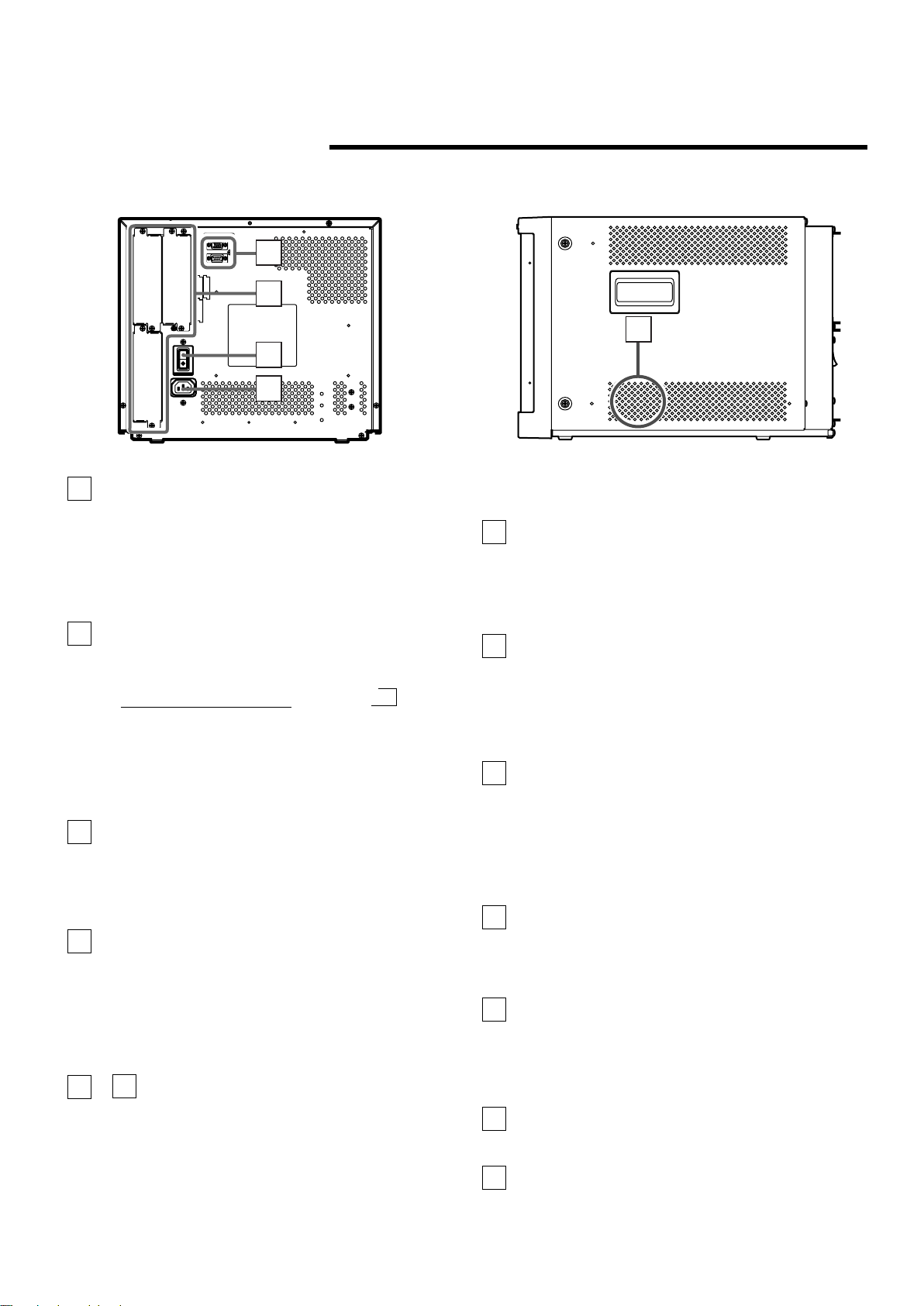
REAR/SIDE VIEW
MAKE
SLOT1
RS-232C
REMOTE
SLOT2
SLOT3
MAIN POWER
24
25
26
27
28
<Rear Panel>
COLOR OFF button/lamp
12
Press the COLOR OFF button. The button lights and the
screen becomes monochrome. When the COLOR OFF
button is pressed while lit, the light goes off and the
normal screen is restored.
Use this function to confirm the noise in the brightness
signal or to confirm the white balance.
NOTE: This function is invalid with the RGB-input screen.
SCREENS CHECK button/lamp
13
Press the SCREENS CHECK button. The button lights
and the screen changes in the following order:
Normal screen[Red screen[Green screen
Blue screenp
[
Press the SCREENS CHECK button when the blue
screen is displayed. The light goes off and the normal
screen is restored.
Use this function to confirm or adjust CHROMA or
PHASE.
NOTE: This function is invalid with the RGB-input screen.
ASPECT button/lamp
14
When the ASPECT button is pressed while the screen
ratio is 4:3, the button lights and the screen ratio changes
to 16:9. When the ASPECT button is pressed while lit, the
light goes off and the normal screen is restored.
NOTE: This function is invalid with the RGB-input screen.
15
AREA MARKER button/lamp
When the AREA MARKER button is pressed while the
screen ratio is 16:9, the button lights and the white
marker is displayed. This shows the screen size (area)
set on the menu. When the AREA MARKER button is
pressed while lit, the light goes off and the normal screen
is restored.
NOTE: This function is invalid with the RGB-input screen.
– INPUT SELECT buttons/lamps
16
21
Press the unlit button. The button lights and the input
signal is changed. (any other lit button goes off.)
When the lit button is pressed, the status of the current
input signal is displayed (for approx. 3 seconds). Buttons
A through F correspond to the signals input via the input
cards installed in SLOT 1 through SLOT 3.
A, B : select the picture from the SLOT 1 input card.
C, D : select the picture from the SLOT 2 input card.
E, F : select the picture from the SLOT 3 input card.
<Side Panel>
Refer to pages 8 and 9 for correspondence between the
input terminals and the INPUT SELECT buttons.
Power lamp
22
Unlit : The main power is OFF.
Orange : The main power is ON, but the monitor’s power
is OFF (in stand-by mode).
Green : The main power is ON, and the monitor’s power
is ON (in normal operation mode).
POWER switch
23
Press the power switch to turn the monitor’s power ON or
OFF when the main power is ON.
NOTE: When RUSH DELAY TIME is set to MODE 2 in
the set-up menu, it takes approx. 3.2 seconds for
the power to actually turn ON after the power
switch is pressed.
REMOTE (external control) terminals
24
Terminals for controlling the monitor from an external unit.
MAKE terminal (Upper):
Enables the monitor to be controlled by closing the circuit
(point of contact) connected to the terminal.
RS-232C terminal (Lower):
Enables the monitor to be controlled from a personal
computer via serial communication.
25
Input card slots (SLOT 1 — SLOT 3)
Optional input cards can be installed in these slots. Input
cards are not provided when you purchase the monitor.
NOTE: It is not possible to input video or audio signals to
the monitor when no input cards are installed.
26
Main power switch
Press the switch to turn the main power ON or OFF.
When the main power is ON, the power lamp on the front
panel lights in yellow and the monitor enters the stand-by
mode.
I : ON 䡬 : OFF
27
AC inlet
Power input connector. Connect the provided AC power
cord to an AC outlet (120 V/230 V AC, 50 Hz/60 Hz).
28
Built-in speaker (monaural)
Outputs the input audio.
ENGLISH
5
Page 6
CONTROLS AND FEATURES
B/PB/B-Y
G/Y
OUTIN
OUTIN
R/PR/B-Y
OUTIN
VD
OUTIN
HD/C
S
OUTIN
OUTIN
AUDIO
OUT
IN
1
2
3
4
VIDEO 1
OUT
IN
AUDIO 2
AUDIO 1
OUT
IN
VIDEO 2
OUT
Y/C IN
IN
OUT
IN
EXT.SYNC
1
2
3
4
5
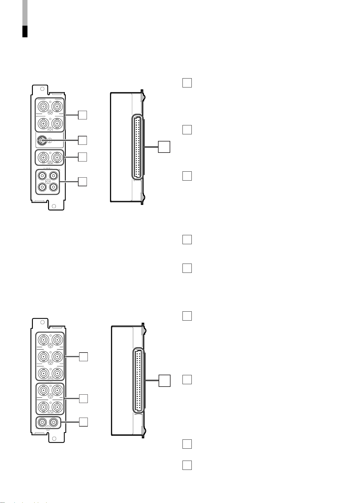
(INPUT CARD: OPTIONAL)
䡵 VIDEO INPUT CARD (OPTIONAL: BT-YA701P)
Video input/output terminals
1
Input (IN) and output (OUT) terminals for video signals.
The IN and OUT terminals are bridge-connected.
(When no cable is connected to the OUT terminal, the
input signal is automatically terminated.)
Select VIDEO 1 : press INPUT SELECT A/C/E button
Select VIDEO 2 : press INPUT SELECT B/D/F button
S-video input terminal
2
Input terminal for the S-video signal.
When an S-video signal is input to this terminal and a
video signal is input to VIDEO 2, the S-video signal has
priority over the video signal.
When choosing the S-video input, press INPUT SELECT
B/D/F button.
3
Synchronised signal input/output terminals
Input (IN) and output (OUT) terminals for the complex
synchronised signals.
The synchronised signals from these terminals have priority
over signals from other terminals. When no synchronised
signal is input to these terminals, the synchronised signal
from the video input/output terminals is valid.
The IN and OUT terminals are bridge-connected.
䡵 Compatible signal formats:
NTSC (3.58 MHz), PAL (4.43 MHz), black-and-white
(50 Hz/60 Hz)
* You can select “AUTO” (automatic selection), “NTSC” or
“PAL ” in SETUP MENU when switching NTSC or PAL.
Normally select AUTO. However, if the input signal is
unstable, select NTSC or PAL.
(When no cable is connected to the OUT terminal, the
input signal is automatically terminated.)
4
Audio input/output terminals
Input (IN) and output (OUT) terminals for audio signals
corresponding to VIDEO 1 and VIDEO 2. The IN and
OUT terminals are bridge-connected.
5
Connection terminal (to a Multi-Format Monitor)
Attach to the connection terminal of your multi-format
monitor.
䡵 COMPONENT/RGB INPUT CARD (OPTIONAL:
BT-YA702P)
Video input/output terminals
1
Input (IN) and output (OUT) terminals for component
(colour deference) or RGB signals.
The IN and OUT terminals are bridge-connected.
(When no cable is connected to the OUT terminal, the
input signal is automatically terminated.)
Select component signal : press INPUT SELECT A/C/E
Select RGB signal : press INPUT SELECT B/D/F
2
Synchronised signal input/output terminals
䡵 Compatible signal formats:
480/60i, 576/50i, 576/50p, 480/60p, 720/60p, 1035/60i,
1080/50i, 1080/60i
6
Input (IN) and output (OUT) terminals for the vertical,
horizontal or complex synchronised signals.
The synchronised signals from these terminals have
priority over other terminals. When no synchronised signal
is input to these terminals, the synchronised signal from
the video input/output terminals (G/Y terminals) is valid.
The IN and OUT terminals are bridge-connected.
(When no cable is connected to the OUT terminal, the
input signal is automatically terminated.)
Audio input/output terminals
3
Input (IN) and output (OUT) terminals for audio signals.
The IN and OUT terminals are bridge-connected.
Connection terminal (to a Multi-Format Monitor)
4
Attach to the connection terminal of your multi-format
monitor.
button
button
Page 7
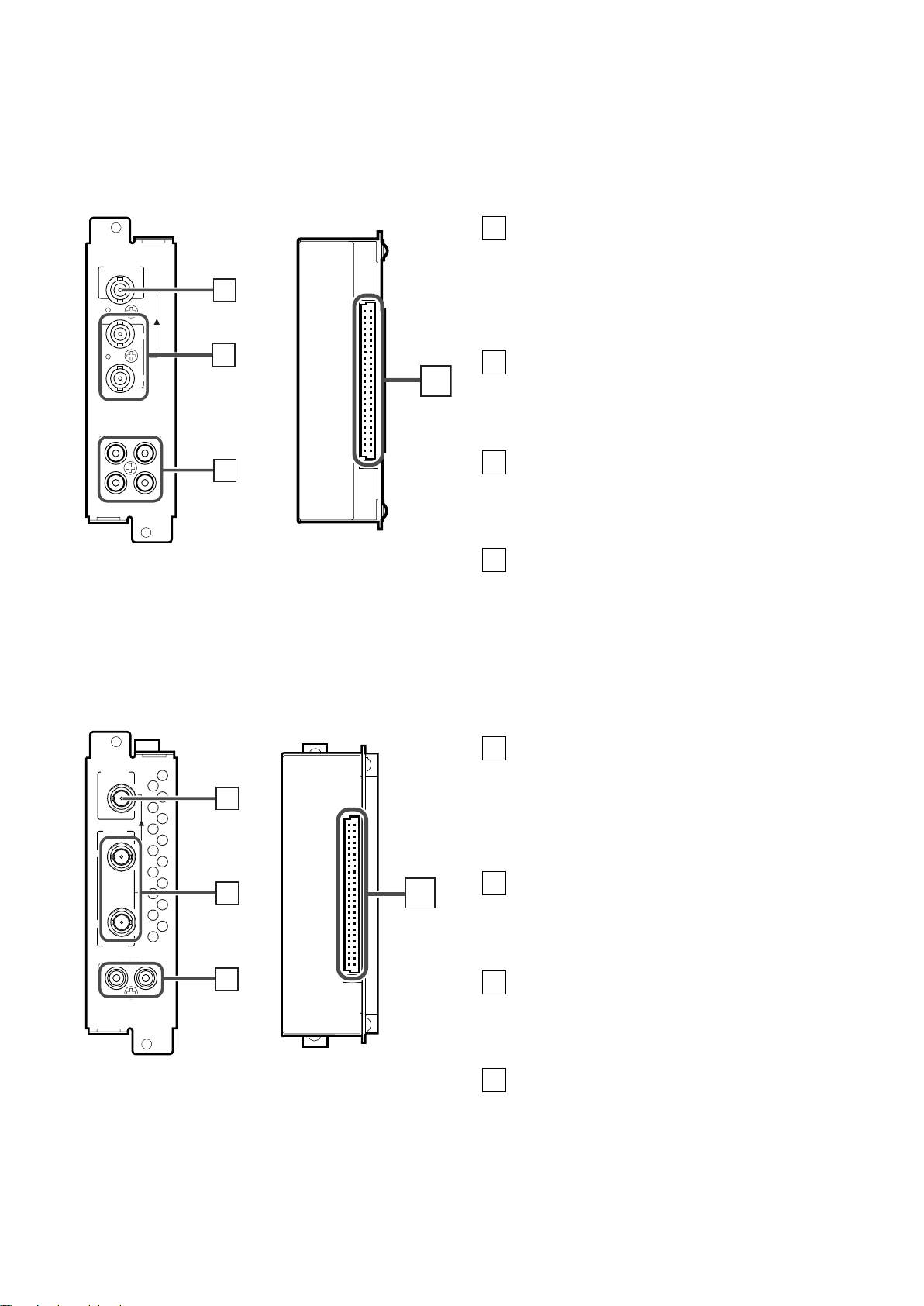
䡵 SDI INPUT CARD (OPTIONAL: BT-YA703P)
AUDIO 2
AUDIO 1
OUT
IN
SWITCHED
OUT
SDI 1
SDI 2
IN
IN
1
2
3
4
AUDIO
OUT
IN
SWITCHED
OUT
HD SDI 1
HD SDI 2
IN
IN
1
2
3
4
Output terminal for a selected component
1
serial digital signal
Output terminal for s selected digital signal (the input
displayed on the screen). The output signal is cablecompensated.
NOTE: When the monitor’s power is OFF, no digital
signal is output.
Input terminals for component serial digital
2
signals
Input terminals for the digital signal.
Select SDI 1 : press INPUT SELECT A/C/E button
Select SDI 2 : press INPUT SELECT B/D/F button
Audio input/output terminals
3
Input (IN) and output (OUT) terminals for the analogue
signals corresponding to SDI 1 and SDI 2.
NOTE: This input card cannot decode audio data even if
contained in the input digital signal.
Connection terminal (to a Multi-Format
4
Monitor)
䡵 Compatible signal formats: 480/60i, 576/50i
Attach to the connection terminal of your multi-format
monitor.
ENGLISH
䡵 HD SDI INPUT CARD (OPTIONAL: BT-YA704P)
Output terminal for a selected component
1
serial digital signal
Output terminal for s selected digital signal (the input
displayed on the screen). The output signal is cablecompensated.
NOTE: When the monitor’s power is OFF, no digital
signal is output.
Input terminals for component serial digital
2
signals
Input terminals for the digital signal.
Select HD SDI 1 : press INPUT SELECT A/C/E button
Select HD SDI 2 : press INPUT SELECT B/D/F button
3
Audio input/output terminals
Input (IN) and output (OUT) terminals for the analogue
䡵 Compatible signal formats: 720/60p, 1035/60i, 1080/50i,
1080/60i, 1080/24psF
audio signals.
NOTE: This input card cannot decode audio data even if
contained in the input digital signal.
Connection terminal (to a Multi-Format
4
Monitor)
Attach to the connection terminal of your multi-format
monitor.
7
Page 8

PREPARATION
䡵 INSTALLING THE INPUT
CARD
Optional input cards are necessary to use the functions of this
monitor. Before mounting the monitor or connecting other
equipment to the monitor, be sure to install the input cards.
1. Turn off the Multi-Format Monitor’s main
power and unplug the power cable from
the AC outlet.
2. Unscrew the screws and remove the slot
cover from the slot (on the rear side of the
monitor) in which you are going to install
the card.
Slot cover
Rear side of the BT-H1700P
multi-format monitor
䡵 ATTACHING THE WIDE
MASK
A wide mask is provided with the monitor. This changes the
viewable screen area to the 16:9 aspect ratio.
The wide mask cannot be attached to the monitor after the
monitor is mounted in a rack. Mount the wide mask before
installing the monitor in a rack.
1. Prepare the provided wide mask and 4
screws (for attaching).
2. Attach the wide mask to the monitor.
3. Insert the Input Card’s board (green-
coloured) into the slot, fitting the board
into the guide rails on the top and bottom
of the slot.
Fit the board to
the guide rails.
Knob
Guide rails
Input card (the illustration shown
Knob
is of the BT-YA701P)
4. Push the Input Card in so that its front
panel touches the monitor’s rear panel.
5. Secure the Input Card by replacing the
screws removed in Procedure 2.
3. Secure the wide mask with the screws (fix
2 screws each to both right and left side).
● When detaching the wide mask, follow this procedure in
reverse.
NOTE :Do not touch the terminal connected to the monitor or
board pattern.
Do not remove slot covers from the monitor’s slots if
they are not in use.
8
Page 9
BASIC MENU OPERATIONS
<SETUP MENU>
FUNCTION SETTING
PICTURE SUB ADJ.
COLOR TEMP/BAL.
SIZE/POSI.ADJ.
DISTORTION ADJ.
STATUS DISPLAY
CONTROL LOCK :ON
all reset
EXIT:
MENU
ENTER:+ SELECT:
<MAIN MENU>
APERTURE CONTROL
SLOT CONDITION
sub menu POSITION :LOWER
AREA MAKER :OFF
AREA MAKER-R :OFF
CENTER MAKER :OFF
COLOR MATRIX
EXIT:
MENU
ENTER:+ SELECT:
<MAIN MENU>
APERTURE CONTROL
SLOT CONDITION
sub menu POSITION :LOWER
COLOR MATRIX
EXIT:
MENU
ENTER:+ SELECT:
<MAIN MENU>
SLOT CONDITION
sub menu POSITION :LOWER
EXIT:
MENU
ENTER:+ SELECT:
MENU
VOLUME
SLOT 1
A
B
DEGAUSS
MENU
BLUE
CHECK
ASPECT
AREA
MARKER
UNDER
SCAN
PULSE
CROSS
COLOR
OFF
SLOT 2
C
D
SLOT 3
POWER
E
F
INPUT SELECT
VOLUME
DEGAUSS
MENU
MENU
MENU
<MAIN MENU>
APERTURE CONTROL
SLOT CONDITION
sub menu POSITION :LOWER
AREA MAKER :OFF
AREA MAKER-R :OFF
CENTER MAKER :OFF
COLOR MATRIX
EXIT:
MENU
ENTER:+ SELECT:
<APERTURE CONTROL>
LEVEL :00
CONTROL FREQ. :HIGH
sub menu
reset
EXIT:
MENU
ENTER:+ SELECT:
MENU
MENU
<PICTURE SUB ADJ.>
CONTRAST :00
BRIGHT :00
CHROMA :00
PHASE :00
NTSC SETUP :00
COMPO.LEVEL :SMPTE
sub menu
reset
EXIT:
MENU
ENTER:+ SELECT:
CONTRAST : 00
- - + +
CONTRAST : 00
- - + +
(MAIN MENU, SETUP MENU)
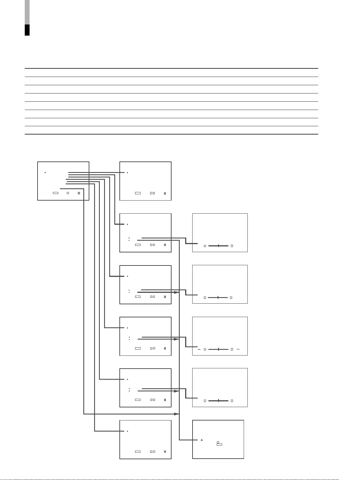
䡵 ABOUT MENU SCREENS
This monitor features a MAIN MENU (main menu screen) and
a SETUP MENU (setup menu screen).
The MAIN MENU contains the functions normally used, and
the SETUP MENU contains the settings required for initial
setup.
MAIN MENU (main menu screen)
NOTE :The contents of menus vary depending on the input
signal or combination of the monitor’s settings.
SETUP MENU
(setup menu screen)
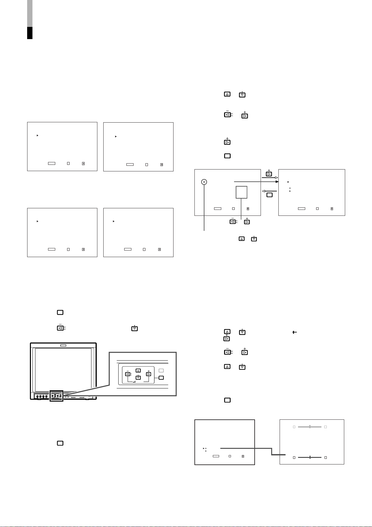
䡵 BASIC MENU OPERATION
● To select an item,
Press the or buttons to move the cursor (4) on the
Menu Screens and select the desired item.
● To set (select) or adjust an item,
Press the
item.
● When the desired item has other menus (hierarchical
menus),
Press the button to display the lower hierarchical menu.
● To return to the former Menu Screen,
Press the
Press the
select or adjust the item.
Cursor
Move (select) with the
or buttons to select or adjust the desired
button.
or buttons to
or buttons.
Menu in an item
ENGLISH
MAIN MENU when the 4:3 video
signal is input
MAIN MENU when the RGB signal
is input
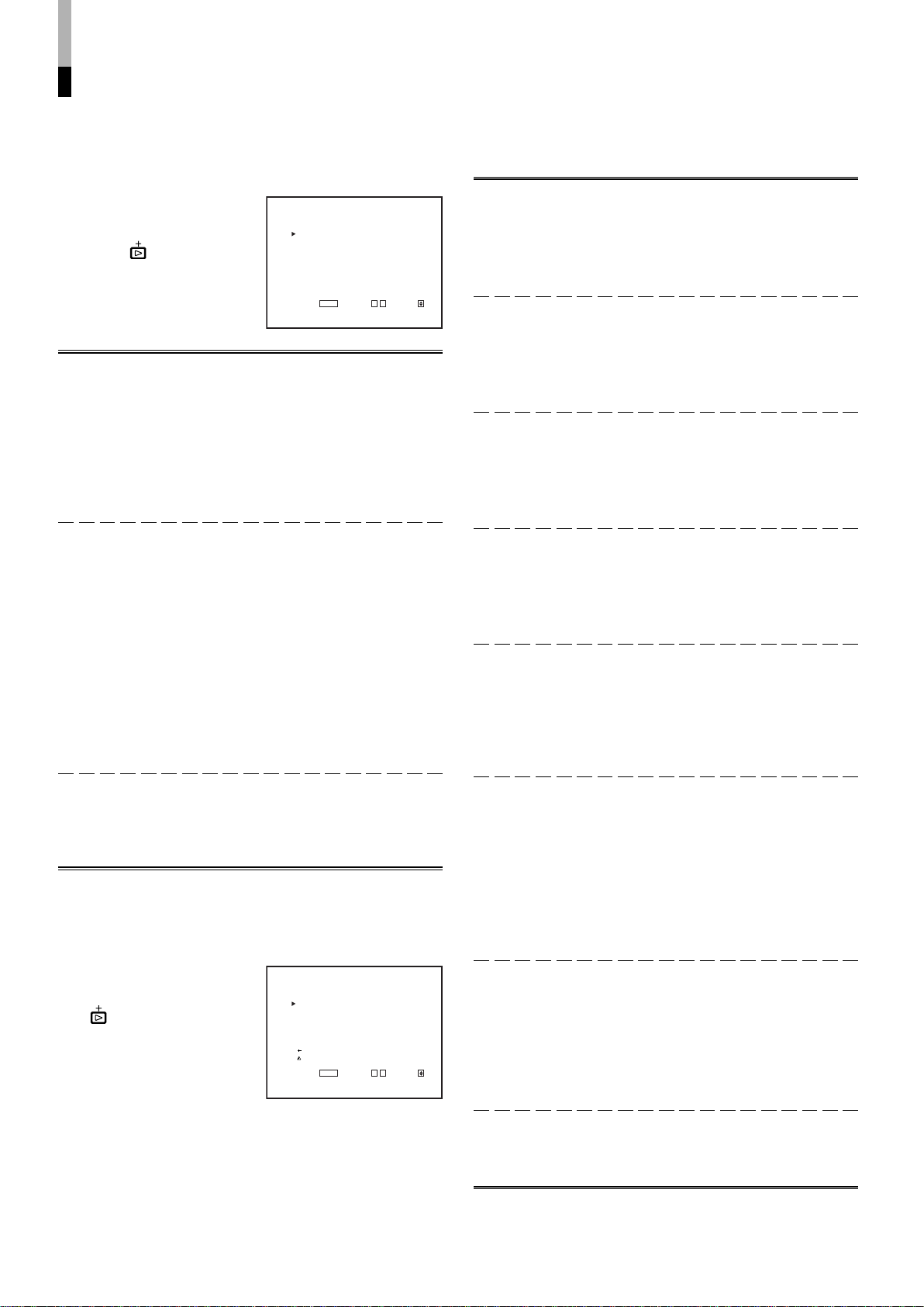
䡵 DISPLAYING THE MENU
SCREENS
● To display MAIN MENU
Press the
button on the front panel.
●To display SETUP MENU
Press the button while pressing the button on the
front panel.
䡵 CLOSING THE MENU
SCREENS
● Using the MENU button
Press the
disappears.
● With no operation
When approx. 30 seconds have passed since the last Menu
operation, both screens will disappear.
* Some items on the Menu Screens disappear automatically
after setting.
NOTE:When you perform the “reset” or “all reset” function, the
button a few times until the Menu Screen
Menu Screen does not disappear unless you press the
MENU button.
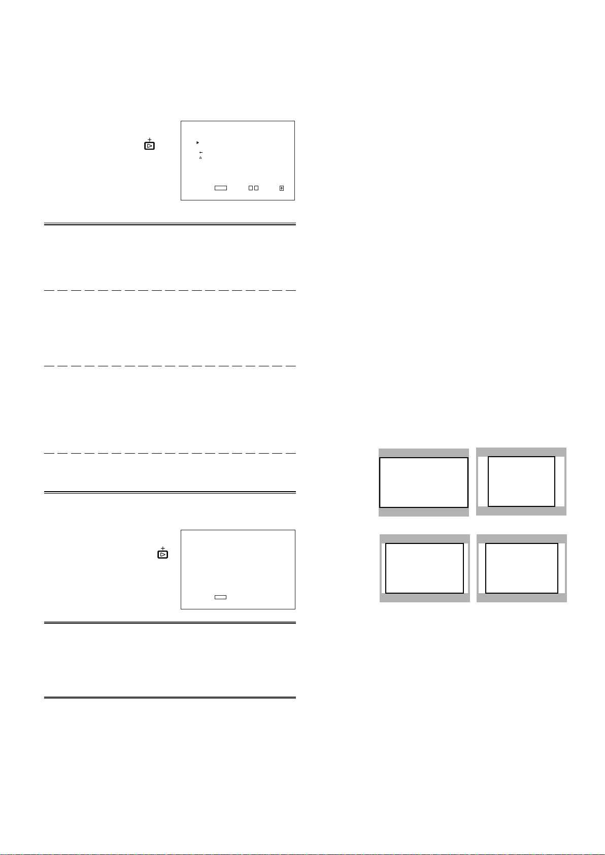
䡵 HOW TO USE THE SUB
MENU
The sub menu function applies to Menu Screen items that
should be adjusted or set while watching the picture. This
function simplifies the adjustment or setting while watching
the picture by displaying the single item on the top or bottom
of the screen.
● To use the sub menu function,
Press the
press the
● To adjust or set an item in the sub menu screen,
Press the or buttons.
● To change the item to be adjusted or set,
Press the
● To change the position of the sub menu screen,
Set “UPPER” (on the top) or “LOWER” (on the bottom) in
“sub menu POSITION” of MAIN MENU.
● To close the sub menu screen,
Press the
displayed.
or buttons to select “ sub menu”. Then,
button to display the sub menu screen.
or buttons.
button. The previous Menu Screen is
Example of sub menu screen
The upper pale screen; when setting
“UPPER” in “sub menu POSITION”
The lower dark screen; when setting
“LOWER” in “sub menu POSITION”
9
Page 10
HOW TO USE “MAIN MENU”
<MAIN MENU>
APERTURE CONTROL
SLOT CONDITION
sub menu POSITION :LOWER
AREA MAKER :OFF
AREA MAKER-R :OFF
CENTER MAKER :OFF
COLOR MATRIX
EXIT:
MENU
ENTER:+ SELECT:
<MAIN MENU>
APERTURE CONTROL
SLOT CONDITION
sub menu POSITION :LOWER
COLOR MATRIX
EXIT:
MENU
ENTER:+ SELECT:
<MAIN MENU>
SLOT CONDITION
sub menu POSITION :LOWER
EXIT:
MENU
ENTER:+ SELECT:
<APERTURE CONTROL>
LEVEL :00
CONTROL FREQ. :HIGH
sub menu
reset
EXIT:
MENU
ADJUST:- + SELECT:
<SLOT CONDITION>
INPUT A : VIDEO-1
INPUT B : VIDEO-2
INPUT C : COMPO.
INPUT D : RGB
INPUT E : NO SLOT
INPUT F : NO SLOT
EXIT:
MENU
<COLOR MATRIX>
SELECT :ITU601
EXIT:
MENU
ADJUST:- + SELECT:
LEVEL :+05
- - + +
LEVEL :+05
- - + +
R-Y PHASE :+90
- - + +
<COLOR MATRIX>
SELECT :MANUAL
R-Y PHASE :90
R/B GAIN :0.86
G-Y PHASE :138
G/B GAIN :0.36
sub menu
reset
EXIT:
MENU
ADJUST:- + SELECT:
䡵 “MAIN MENU” ITEMS
The following items appear in MAIN MENU.
Items
1 APERTURE CONTROL Compensates the frequency characteristics of the input video signal. *1
2 SLOT CONDITION Displays the status of the input cards installed in each of the input card slots.
3 sub menu POSITION Selects the display position of the sub menu superimposed on the screen.
4 AREA MARKER Selects the size marker for the other screen ratio used when the screen
5 AREA MARKER-R Selects the size marker for the other screen ratio used when the screen ratio is
6 CENTER MARKER Makes the centre marker appear or disappear. *2
7 COLOR MATRIX Selects or adjusts the picture colour matrix. *1
Functions Displays
ratio is 16:9.
16:9. (for external control)
*2
*2
About “Displays” *1: Not displayed when an RGB signal is input.
*2: Displayed only when the screen ratio is 16:9. Not displayed when an RGB signal is input.
When some items are not displayed depending on the input signals, subsequent items will move up.
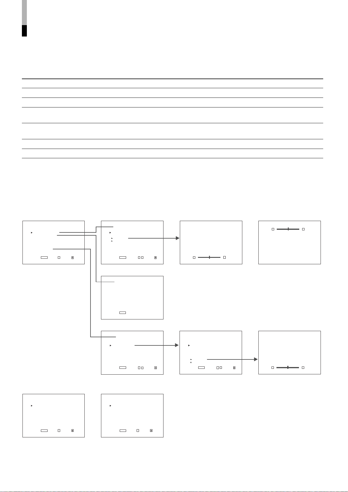
䡵 “MAIN MENU” SCREENS
The menu screen when “sub
menu” is selected.
The sub menu screen when
“sub menu POSITION” is set
to “UPPER”.
The menu screen when the
screen ratio is 4:3
10
The menu screen when an
RGB signal is input
The menu screen when
“MANUAL” is selected.
The menu screen when “sub
menu” is selected.
Page 11
<SLOT CONDITION>
INPUT A : VIDEO-1
INPUT B : VIDEO-2
INPUT C : COMPO.
INPUT D : RGB
INPUT E : NO SLOT
INPUT F : NO SLOT
EXIT:
MENU
䡵 ITEM CONTENTS AND ADJUSTMENT RANGE/SETTINGS
16:9
4:3
14:9 13:9
<APERTURE CONTROL>
LEVEL :00
CONTROL FREQ. :HIGH
sub menu
reset
EXIT:
MENU ADJUST:- + SELECT:
1. APERTURE CONTROL
Compensates the frequency
characteristics of the input
video signal. Press the
button to display the setting
menu illustrated on the right.
NOTE :APERTURE
CONTROL is not
displayed when the
RGB signal is input.
Item : LEVEL
Adjustment
range : 00 ~ +10
Function : Adjusts the compensate value. The higher the
number is, the larger the compensate value gets.
Item : CONTROL FREQ.
Settings : HIGH/LOW/OFF
Function : Adjusts the frequency compensation.
HIGH : Compensates the high frequencies.
LOW : Compensates the low frequencies.
OFF : Deactivates the aperture compensation.
Item : sub menu
Adjustment range/
Settings : Same as LEVEL or CONTROL FREQ.
Function : Performs the LEVEL or CONTROL FREQ.
settings in a single-line display. The display
position depends on the “sub menu POSITION”
setting.
3. sub menu POSITION
Items : Selects the display position of the sub menu
superimposed on the screen.
Settings : UPPER/LOWER
Functions : UPPER : An adjustment item is displayed on the
top of the screen.
LOWER : An adjustment item is displayed on the
bottom of the screen.
4. AREA MARKER
Items : Selects the size marker for the other screen ratio
(aspect) used when the screen ratio is 16:9.
Settings : OFF/16:9/4:3/13:9/14:9/MODE 1/MODE 2
Functions : OFF: The marker is not displayed.
16:9/4:3/13:9/14:9: Displays the marker (a white
quadrangle) showing the screen size of each
aspect ratio.
MODE 1/MODE 2: Displays no markers because
these settings will be used for function expansion
in the future.
● AREA MARKER is displayed when a 16:9 picture such as
1080i/1035i/720p etc. is displayed or the picture is
switched to the 16:9 screen ratio by pressing the ASPECT
button.
● To actually display the marker, the AREA MARKER
button on the monitor needs to be pressed so that it is
illuminated.
ENGLISH
Item : reset
Function : Sets the LEVEL and CONTROL FREQ. values to
factory-preset ones.
2. SLOT CONDITION
Displays the status of the input
cards installed in each of the
input card slots. Press the
button to display the setting
menu illustrated on the right.
Items : INPUT A:/INPUT B:/INPUT C:/INPUT D:/INPUT
E:/INPUT F:
Settings : VIDEO-1/VIDEO-2/COMPO./RGB/SDI 1/SDI 2/
HD SDI 1/HD SDI 2/NO SLOT
Function : Displays the status of the input cards installed in
each of the input card slots.
● INPUT A/B corresponds to SLOT 1, INPUT C/D to SLOT 2,
and INPUT E/F to SLOT 3.
● VIDEO-1 or VIDEO-2 shows the video input card is installed.
COMPO. or RGB shows the component/RGB input card.
SDI 1 or SDI 2 shows the SDI input card is installed.
HD SDI 1 or HD SDI 2 shows the HD SDI input card is
installed.
● NO SLOT shows no input cards are installed.
11
Page 12
<COLOR MATRIX>
SELECT :MANUAL
R-Y PHASE :90
R/B GAIN :0.86
G-Y PHASE :244
G/B GAIN :0.30
sub menu
reset
EXIT:
MENU
ADJUST:- + SELECT:
5. AREA MARKER-R
Items : Selects the size marker for the other screen ratio
(aspect) used when the screen ratio is 16:9. (for
external control)
Settings : OFF/16:9/4:3/13:9/14:9/MODE 1/MODE 2
Functions : OFF: The marker is not displayed.
16:9/4:3/13:9/14:9: Displays the marker (a white
quadrangle) showing the screen size of each
aspect ratio.
MODE 1/MODE 2: Displays no markers because
these settings will be used for function expansion
in the future.
●AREA MARKER-R is displayed when a 16:9 picture such
as 1080i/1035i/720p etc. is displayed or the picture is
switched to the 16:9 screen ratio by pressing the ASPECT
button.
●The marker is actually displayed when the external control
selects each setting. (No markers are displayed even if
each marker is selected only in the monitor’s AREA
MARKER-R setting.)
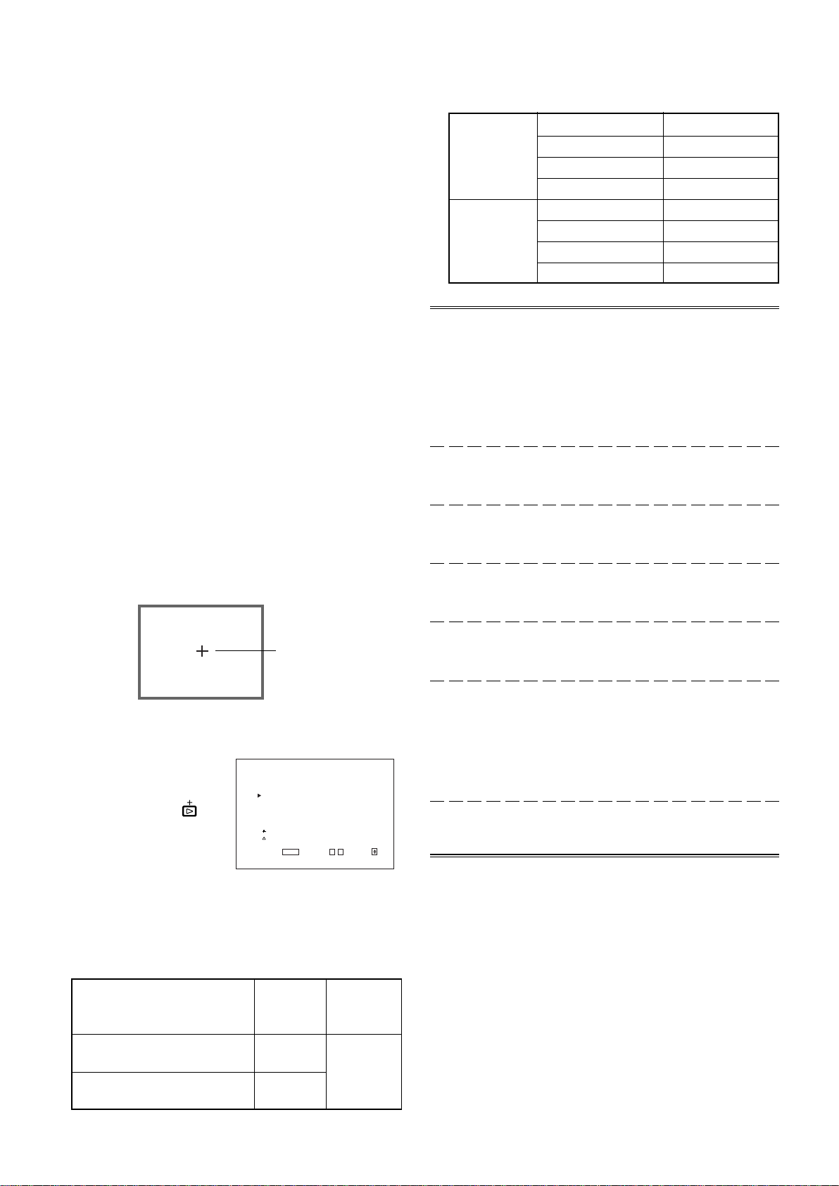
6. CENTER MARKER
Items : Makes the centre marker appear or disappear.
Settings : ON/OFF
Functions : ON : The centre marker (a white cross) is
displayed on the centre of the screen.
OFF : The marker disappears.
●To actually display the marker, the AREA MARKER
button on the monitor needs to be pressed so that it is
illuminated.
R-Y PHASE 90
ITU601
R/B GAIN 0.79
G-Y PHASE 244
G/B GAIN 0.45
R-Y PHASE 90
ITU709
R/B GAIN 0.86
G-Y PHASE 244
G/B GAIN 0.30
Item : SELECT
Function : Selects the picture matrix standard.
Settings : ITU601 or ITU709/ MANUAL
ITU601 or ITU709 : Standard setting
MANUAL : Manual setting
NOTE :The following items are displayed when MANUAL is
selected. When ITU601 or ITU709 is selected, they
are not displayed.
Item : R-Y PHASE
Function : Sets the R-Y phase.
Settings : 90/92/94/112
Item : R/B GAIN
Function : Sets the R/B gain.
Settings : 0.86/0.56/0.68/0.79
Item : G-Y PHASE
Function : Sets the G-Y phase.
Settings : 244/253/236/240
7. COLOR MATRIX
Selects or adjusts the
standard of the colour
demodulation (colour
rendering). Press the
button to display the setting
menu illustrated on the right.
The menu screen when
MANUAL is selected.
● The standard setting is set to “ITU601” or “ITU709”
depending on the input signal format.
The factory preset of MANUAL is ITU709
Input Signal Format Standard Manual
setting setting
NTSC, PAL, 480/60i,
480/60p, 576/50i, 575/50p
12
720/60p, 1080/50i, 1080/60i,
1035/60i, 1080/24psF
ITU601
ITU709
Centre marker
(MANUAL)
Item : G/B GAIN
Function : Sets the G/B gain.
Settings : 0.30/0.34/0.40/0.45
Item : sub menu
Function : Performs the R-Y PHASE, R/B GAIN, G-Y
PHASE or G/B GAIN settings in a single-line
display. The display position depends on the
“sub menu POSITION” setting.
Settings : Same as R-Y PHASE, R/B GAIN, G-Y PHASE or
G/B GAIN
Item : reset
Function : Sets the R-Y PHASE, R/B GAIN, G-Y PHASE
and G/B GAIN values to factory-preset ones.
ITU709
Page 13
HOW TO USE “SETUP MENU”
<SETUP MENU>
FUNCTION SETTING
PICTURE SUB ADJ.
COLOR TEMP./BAL.
SIZE/POSI.ADJ.
DISTORTION ADJ.
STATUS DISPLAY
CONTROL LOCK :ON
all reset
EXIT:
MENU
ENTER:+ SELECT:
<FUNCTION SETTING>
COLOR SYSTEM :AUTO
RUSH DELAY TIME :STD.
HOUR METER X100h :000
EXIT:
MENU
ADJUST:- + SELECT:
<PICTURE SUB ADJ.>
CONTRAST :00
BRIGHT :00
CHROMA :00
PHASE :00
NTSC SETUP :00
COMPO.LEVEL :SMPTE
sub menu
reset
EXIT:
MENU
ADJUST:- + SELECT:
<COLOR TEMP./BAL.>
COLOR TEMP. :LOW
BLUE DRIVE :000
RED DRIVE :000
GREEN CUTOFF :000
BLUE CUTOFF :000
RED CUTOFF :000
sub menu
reset
EXIT:
MENU
ADJUST:- + SELECT:
<SIZE/POSI. ADJ.>
H.SIZE :00
H.POSITION :00
V.SIZE :00
V.POSITION :00
sub menu
reset
EXIT:
MENU
ADJUST:- + SELECT:
<DISTORTION ADJ.>
PINCUSHION :00
PIN.BALANCE :00
PARALLELOGRAM :00
TRAPEZOID :00
sub menu
reset
EXIT:
MENU
ADJUST:- + SELECT:
<STATUS DISPLAY>
STATUS DISPLAY :ON
1080/1035 :1080
EXIT:
MENU
ADJUST:- + SELECT:
CONTRAST : 00
- - + +
BLUE DRIVE :000
- - + +
H.SIZE : 00
- - + +
PINCUSHION : 00
- - + +
Aer you sure ?
"Yes" then + Key.
"No" then
MENU
Key.
䡵 “SETUP MENU” ITEMS
Items Functions
1 FUNCTION SETTING Displays the monitor’s power-up time or the total usage time.
2 PICTURE SUB ADJ. Performs approximate adjustments using the control knobs on the front panel.
3 COLOR TEMP./BAL. Sets or adjusts the colour temperature or white balance.
4 SIZE/POSI. ADJ. Adjusts the size or position of the picture.
5 DISTORTION ADJ. Compensates the picture distortion.
6 STATUS DISPLAY Makes the status of the input signal appear or disappear on the screen.
7 CONTROL LOCK Sets the control lock preventing the monitor from misuse.
8 all reset Sets all items in SETUP MENU to factory-preset values.
䡵 “SETUP MENU” SCREENS
ENGLISH
13
Page 14
HOW TO USE “SETUP MENU” (cont'd)
<FUNCTION SETTING>
COLOR SYSTEM :AUTO
RUSH DELAY TIME :STD.
HOUR METER X100h :000
EXIT:
MENU
ADJUST:- + SELECT:
<PICTURE SUB ADJ.>
CONTRAST :00
BRIGHT :00
CHROMA :00
PHASE :00
NTSC SETUP :00
COMPO.LEVEL :SMPTE
sub menu
reset
EXIT:
MENU
ADJUST:- + SELECT:
䡵 ITEM CONTENTS AND ADJUSTMENT RANGE/SETTINGS
1. FUNCTION SETTING
Selects the colour system and
displays the monitor’s powerup time or the total usage time.
Press the
the setting menu illustrated on
the right.
Item : COLOR SYSTEM
Settings : AUTO/NTSC/PAL
Function : Selects the colour system when using the video
NOTE :Normally select AUTO. However, if the input signal is
Item : RUSH DELAY TIME
Settings : STD./SLOW
Function : Sets the time when the power supply to the
NOTE :When turning on many multi-format monitors
button to display
input card.
AUTO : Change NTSC and PAL automatically.
NTSC : Keeps the colour system NTSC.
PAL : Keeps the colour system PAL.
unstable, select NTSC or PAL.
monitor’s circuits (excluding the micro computers)
starts after the power switch is pressed.
STD. : The power supply starts approx.
1 second after the power switch is
pressed.
SLOW : The power supply starts approx.
3.2 seconds after the power switch is
pressed.
simultaneously, it is recommended to use SLOW to
control rush current.
Item : CONTRAST
Adjustment
range : –20 ~ 00 ~ +20
Function : For approximate adjustment of the picture
contrast. Before adjustment, set the CONTRAST
knob on the front panel to 0.
Item : BRIGHT
Adjustment
range : –20 ~ 00 ~ +20
Function : For approximate adjustment of the picture
brightness. Before adjustment, set the BRIGHT
knob on the front panel to 0.
Item : CHROMA
Adjustment
range : –20 ~ 00 ~ +20
Function : For approximate adjustment of the colour
density. Before adjustment, set the CHROMA
knob on the front panel to 0.
Item : PHASE
Adjustment
range : –20 ~ 00 ~ +20
Function : For approximate adjustment of the picture hue.
Before adjustment, set the PHASE knob on the
front panel to 0.
Item : NTSC SETUP
Settings : 00/7.5
Function : Sets the level of the input NTSC signal.
00 : Compliant with 0% set-up signal.
7.5 : Compliant with 7.5% set-up signal.
NOTE :NTSC SETUP is displayed only when the video input
card is installed and an NTSC signal is input.
Item : HOUR METER X100h
Number
range : 000 ~ 655
Function : Displays the total usage time of the monitor in
hundred-hour units.
● When the timer passes 655, it returns to 000.
● The timer does not count the usage time under one hour.
2. PICTURE SUB ADJ.
Performs approximate
adjustments using the control
knobs on the front panel. Press
button to display the
the
setting menu illustrated on the
right.
NOTE : When the RGB signal
is input, only
CONTRAST and
BRIGHT are displayed. When the PAL signal is
input, only CONTRAST, BRIGHT and CHROMA are
displayed.
14
Item : COMPO. LEVEL
Settings : SMPTE/B75/B00
Function : Sets the level of the input component signal.
SMPTE : Compliant with M2VTR signals.
B75 : Compliant with Betacam 7.5% set-up
signal.
B00 : Compliant with Betacam 0% set-up
signal.
NOTE :COMPO. LEVEL is displayed only when a 480/60i,
480/60p, 576/50i or 576/50p signal is input.
Item : sub menu
Adjustment range/
Settings : Same as CONTRAST, BRIGHT, CHROMA,
PHASE and COMPO. LEVEL/NTSC SETUP.
Function : Performs CONTRAST, BRIGHT, CHROMA,
PHASE or COMPO. LEVEL/NTSC SETUP
settings in a single-line display. The sub menu
display varies depending on the selected item.
Item : reset
Function : Sets the CONTRAST, BRIGHT, CHROMA,
PHASE and COMPO. LEVEL/NTSC SETUP
values to factory-preset ones.
Page 15

<COLOR TEMP./BAL.>
COLOR TEMP. :LOW
BLUE DRIVE :000
RED DRIVE :000
GREEN CUTOFF :000
BLUE CUTOFF :000
RED CUTOFF :000
sub menu
reset
EXIT:
MENU
ADJUST:- + SELECT:
<SIZE/POSI. ADJ.>
H.SIZE :00
H.POSITION :00
V.SIZE :00
V.POSITION :00
sub menu
reset
EXIT:
MENU
ADJUST:- + SELECT:
3. COLOR TEMP./BAL.
Sets or adjusts the colour
temperature or white balance.
Press the
the setting menu illustrated on
the right.
button to display
4. SIZE/POSI. ADJ.
Adjusts the size or position of
the picture. Press the
button to display the setting
menu illustrated on the right.
Item : COLOR TEMP.
Settings : HIGH/LOW
Function : Selects the colour temperature.
HIGH : Sets the colour temperature to D93.
LOW : Sets the colour temperature to D65™.
Item : BLUE DRIVE
Adjustment
range : MIN ~ 000 ~ MAX (in 127 grades)
Function : Adjusts the blue drive level.
Item : RED DRIVE
Adjustment
range : MIN ~ 000 ~ MAX (in 127 grades)
Function : Adjusts the red drive level.
Item : GREEN CUTOFF
Adjustment
range : MIN ~ 000 ~ MAX (in 255 grades)
Function : Sets the green cut-off point.
Item : BLUE CUTOFF
Adjustment
range : MIN ~ 000 ~ MAX (in 255 grades)
Function : Sets the blue cut-off point.
Item : RED CUTOFF
Adjustment
range : MIN ~ 000 ~ MAX (in 255 grades)
Function : Sets the red cut-off point.
Item : sub menu
Adjustment range/
Settings : Same as BLUE DRIVE, RED DRIVE, GREEN
CUTOFF, BLUE CUTOFF and RED CUTOFF.
Function : Performs BLUE DRIVE, RED DRIVE, GREEN
CUTOFF, BLUE CUTOFF or RED CUTOFF
settings in a single-line display. The sub menu
display varies depending on the selected item.
Item : reset
Function : Sets the BLUE DRIVE, RED DRIVE, GREEN
CUTOFF, BLUE CUTOFF and RED CUTOFF
values to factory-preset ones.
Item : H.SIZE
Adjustment
range : –20 ~ 00 ~ +20 ( * )
Function : Adjusts the horzitontal screen size.
– : Reduces the screen size horizontally.
+ : Enlarges the screen size horizontally.
* : Reduced to 00 ~ +20 during the under-scan mode.
Item : H.POSITION
Adjustment
range : –20 ~ 00 ~ +20
Function : Adjusts the horzitontal screen position.
– : Move the screen to the left.
+ : Move the screen to the right.
Item : V.SIZE
Adjustment
range : –20 ~ 00 ~ +20
Function : Adjusts the vertical screen size.
– : Reduces the screen size vertically.
+ : Enlarges the screen size vertically.
Item : V.POSITION
Adjustment
range : –20 ~ 00 ~ +20
Function : Adjusts the vertical screen position.
– : Move the screen up.
+ : Move the screen down.
Item : sub menu
Adjustment range/
Settings : Same as H.SIZE, H.POSITION, V.SIZE and
V.POSITION.
Function : Performs H.SIZE, H.POSITION, V.SIZE or
V.POSITION settings in a single-line display. The
sub menu display varies depending on the
selected item.
Item : reset
Function : Sets the H.SIZE, H.POSITION, V.SIZE and
V.POSITION values to factory-preset ones.
ENGLISH
15
Page 16

<STATUS DISPLAY>
STATUS DISPLAY :ON
1080/1035 :1080
EXIT:
MENU
ADJUST:- + SELECT:
<DISTORTION ADJ.>
PINCUSHION :00
PIN.BALANCE :00
PARALLELOGRAM :00
TRAPEZOID :00
sub menu
reset
EXIT:
MENU
ADJUST:- + SELECT:
5. DISTORTION ADJ.
Compensates the picture
distortion. Press the
to display the setting menu
illustrated on the right.
button
6. STATUS DISPLAY
Makes the status of the input
signal appear or disappear on
the screen. Press the
button to display the setting
menu illustrated on the right.
Item : PINCUSHION
Adjustment
range : –20 ~ 00 ~ +20
Function : Compensates pincushion picture distortion.
– : Expands both left and right sides of the
picture.
+ : Squeezes both left and right sides of the
picture.
Item : PIN.BALANCE
Adjustment
range : –20 ~ 00 ~ +20
Function : Adjusts the compensation balance of the
pincushion picture distortion.
– : The picture is expanded on the left side, and
squeezed on the right side.
+ : The picture is squeezed on the left side, and
expanded on the right side.
Item : PARALLELOGRAM
Adjustment
range : –20 ~ 00 ~ +20
Function : Compensates parallelogram picture
distortion.
– : Moves the upper side of the picture to the
right, and the lower side to the left.
+ : Moves the upper side of the picture to the left,
and the lower side to the right.
Item : TRAPEZOID
Adjustment
range : –20 ~ 00 ~ +20
Function : Compensates trapezoid picture distortion.
– : Enlarges the upper side of the picture.
+ : Reduces the upper side of the picture.
Item : sub menu
Adjustment range/
Settings : Same as PINCUSHION, PIN.BALANCE,
PARALLELOGRAM and TRAPEZOID.
Function : Performs PINCUSHION, PIN.BALANCE,
PARALLELOGRAM or TRAPEZOID settings in a
single-line display. The sub menu display varies
depending on the selected item.
Item : STATUS DISPLAY
Settings : ON/OFF
Function : Makes the format name appear or disappear
when signals are input and the signal status
appear or disappear when the input signal is
changed.
ON : The information is displayed.
OFF : The information is not displayed.
Item : 1080/1035
Settings : 1080/1035
Function : Makes the number of effective scanning lines
appear or disappear when the HDTV signal is
input.
1080 : Sets the number to 1080. (Select when
the digital HDTV signal is input.)
1035 : Sets the number to 1035. (Select when
the analogue HDTV signal is input.)
7. CONTROL LOCK
Item : CONTROL LOCK
Settings : OFF/ON
Function : Invalidates most of operations on the front panel
(including menu screen operations).
OFF : Enables normal operations.
ON : Invalidates all operations except the power
switch and CONTROL LOCK.
NOTE: While CONTROL LOCK is set to ON, attempting to
perform any operation except power switch and
CONTROL LOCK causes the “
Control lock on!”
warning to appear on the screen for approx. 3
seconds. (It is possible to operate the power switch
and display SETUP MENU.)
When SETUP MENU is displayed while CONTROL
4
LOCK is set to ON, the cursor (
) is located next to
CONTROL LOCK and cannot be moved.
8. all reset
Function : Sets all items in SETUP MENU to factory-preset
values.
Item : reset
Function : Sets the PINCUSHION, PIN.BALANCE,
PARALLELOGRAM and TRAPEZOID values to
16
factory-preset ones.
Page 17

HOW TO USE EXTERNAL
10 9 8
54321
7
6
1415 13 12 11
CONTROL
䡵 ABOUT EXTERNAL CONTROL
This multi-format monitor has two external control terminals. One is the MAKE terminal, which controls the monitor by connecting
the terminals with many functions to the ground (GND) terminal. The other is the RS-232C terminal, which allows the monitor to
be controlled by a PC via serial communication.
Control priority is in the following order; the MAKE terminal > the RS-232C terminal > the buttons on the front panel.
䡵 HOW TO USE THE MAKE TERMINAL
Connections
Connect (short-circuit) the 15th terminal (GND) to each of the 1st through 14th terminals in the
3-lines 15-pins D-sub connector. The functions of each terminal are listed below.
The Names and Functions of Terminals
No. Names Functions Operations (OFF p[ ON) *1
1 TALLY Puts on the tally lamp. Put on Put off
2 INPUT A Changes the input to INPUT A Not change Change
3 INPUT B Changes the input to INPUT B Not change Change
4 INPUT C Changes the input to INPUT C Not change Change
5 INPUT D Changes the input to INPUT D Not change Change
6 INPUT E Changes the input to INPUT E Not change Change
7 INPUT F Changes the input to INPUT F Not change Change
8 COLOR OFF Changes the picture black-and-white. Not change Change
9 AREA MARKER Displays the area marker. Not display Display
10 ASPECT Changes the screen ratio to 16:9 4:3 16:9
11 UNDER SCAN Makes the screen under-scan Over-scan Under-scan
12 MARKER Selects the type of the area marker Selection in the main unit Selection in the remote *2
control
13 STATUS Displays the monitor’s status Display *3
14 REMOTE ENABLE Makes the external control form the Invalid Valid *4
MAKE terminal valid or invalid
15 GND Used as a ground terminal ––
*1 : OFF stands for disconnection, and ON stands for short-circuit.
*2 : Selects the area marker size from AREA MARKER (setting on the main unit) or AREA MARKER-R (setting on the remote control) setting.
*3 : The STATUS function is activated when the connection to the STATUS terminal is changed (ON to OFF, or OFF to ON). The monitor’s status
is displayed for 3 seconds.
*4 : Setting REMOTE ENABLE to ON enables remote control from the MAKE terminal.
ENGLISH
Operation
Changing the Signal Input
NOTE : When more than two terminals are selected (short-circuited) from INPUT A through INPUT F, the signal input is not
1. Set REMOTE ENABLE to ON.
2. Short-circuit or disconnect the desired terminal.
1. Set REMOTE ENABLE to ON.
2. Short-circuit the desired INPUT terminal.
3. Disconnect the INPUT terminal selected above. The signal input is actually changed after the disconnection has been
completed.
changed.
To control INPUT A through INPUT F, we recommend using the interlock switch, which turns off a switch when another
switch is turned on.
17
Page 18

HOW TO USE EXTERNAL
4
3
2
1
9
8
5
7
6
CONTROL
(cont.)
䡵 HOW TO USE THE RS-232C TERMINAL
You can control the monitor from your PC via the RS-232C terminal.
For details on operating the monitor from the PC, consult your dealer or service centre for details.
1. Cable
Prepare a straight cable with a D-sub connector (9-pin, female) and a D-sub
connector (9-pin, male)
2. Communications Specifications
Baud Rate : 4800/9600/19200 (factory pre-set; 4800)
Data Bits : 8 bits
Parity : No parity
Stop Bits : 1
Flow Control : Hardware (RTS/CTS)
3. Commands
Format
Header ID Command Data CR
Header
! Control from the PC to the monitor
? Reference from the PC to the monitor
@ Answer from the monitor to the PC
Pin No. Signal
1 DCD (Data Carrier Detect)
2 RD (Recive Data)
3 TD (Transmit Data)
4 DTR (Data Terminal Ready)
5 GND (Ground)
6 DSR (Data Set Ready)
7 RTS (Request To Send)
8 CTS (Clear To Send)
9 RI (Ring Indication)
ID + Command + Data
B Basic command Characters 00, 01 or No data
D Command for adjusting the picture size 00 ~ 07 –20 ~ +20
S Command for adjusting the picture quality 00 ~ 05 –20 ~ +20
M Command for selecting the menu item 00 ~ 0E 00, 01, 10, 11
F Command for selecting the menu item 00 ~ 07 00, 01
W Command for adjusting the white balance 00 ~ 05 –256 ~ +255
C Command for inquiring for the monitor’s status 00 0 ~ 655
During Communication from the PC to the Monitor
The monitor receives the data when DSR remains ON (high) and CTS is set to ON.
During Communication from the Monitor to the PC
The monitor sends the data when both DSR and DCD are set to ON and RTS is set to ON.
Communication Procedures
The following is the communication procedures.
1. Starting the communication
Receives the connection command (!BCN1Cr) from the PC [ Sends the monitor’s status (@BOKCr) to the PC
2. Performing the external control
Receives the control command (!XXXXCr) from the PC [ Sends the monitor’s status (@BOKCr) to the PC
* The monitor repeats these receiving and sending if necessary.
3. Terminating the communication
Receives the termination command (!BCN0Cr) [ Sends the monitor’s status (@BOKCr) to the PC
* After sending the data to the monitor, the PC must first receive the data from the monitor and then send the next command
because the communication is performed in a hand-shake system. If the PC does not receive the status from the monitor after
sending the command, re-send the command.
18
Page 19

TROUBLESHOOTING
Solutions to common problems related to your monitor are described here. If none of the solutions presented here solve
the problem, unplug the monitor and consult a JVC-authorised dealer or service centre for assistance.
Problems
No power supply
No picture with
the power on
No sound
Wrong colour
Unnatural picture
Shaking picture
Points to be checked
Is the power plug loosened or
disconnected?
Is the signal cable disconnected?
Is the power of the connected
component ON?
Is the signal output from the connected
component?
Is the input signal selected correctly?
Is the input signal adapted to the
monitor’s specification?
Is the audio cable disconnected?
Is the audio signal output from the
connected component?
Is the volume output set to minimum?
Has the picture adjustment been
changed?
Has the WHITE BALANCE setting
been changed?
Are any cables connected to the
component/RGB input card?
Has the correct signal been input to the
component/RGB input card and the
correct INPUT been selected on the
monitor?
Has [CONTRAST] or [BRIGHT] been
changed?
Is the monitor close to a motor,
transformer or any other device
generating a strong magnetic field?
(a fan, fluorescent light, laser printer,
another monitor, etc.)
Measures (Remedy)
Firmly insert the power plug.
Connect the signal cable firmly.
Turn on the power of the connected component
and set it correctly.
Select the correct input with the INPUT SELECT
buttons.
Check that the input signal format corresponds to
the installed input card format.
Connect the audio cable firmly.
Set the connected component correctly.
Adjust the speaker volume with the VOLUME
+/– buttons.
Set each picture adjustment knob to the standard
(centred) position. Or, set each picture
adjustment item in [ PICTURE SUB ADJ.] in the
<SETUP MENU> screen to Standard (00) (or
use the [reset] function).
Set each [COLOR TEMP./BAL.] item in the
<SETUP MENU> screen to Standard (000) (or
use the [reset] function).
Connect each signal cable firmly.
Select INPUT A/C/E when the component signal
is input, or select INPUT B/D/F when the RGB
signal is input.
Adjust the CONTRAST or BRIGHT picture
adjustment knobs.
Or, adjust the [CONTRAST] or [BRIGHT] item in
[PICTURE SUB ADJ.] in the <SETUP MENU>
screen.
Move the monitor away from the device until the
picture stops shaking.
Connect the power plug to another AC outlet
away from the former one.
Reference
pages
5
6, 7
—
5, 8
6, 7
6, 7
—
4
ENGLISH
9, 14
15
6
6
14
—
19
Page 20

VOLUME
SLOT 1
A
B
DEGAUSS
MENU
BLUE
CHECK
ASPECT
AREA
MARKER
UNDER
SCAN
PULSE
CROSS
COLOR
OFF
SLOT 2
C
D
SLOT 3
POWER
E
F
INPUT SELECT
TROUBLESHOOTING (cont.)
Problems
Irregular colour
Wrong picture
position, wrong
picture size
Front panel
buttons and
knobs do not
function
Points to be checked
Is the monitor placed or moved close to
a speaker or any other device
incorporating a magnet?
Has the position of the monitor been
changed with the power on?
Has the picture position, size or
distortion been changed?
Have the UNDER SCAN or ASPECT
button been pressed?
Has the CONTROL LOCK function
been set to ON?
Has the monitor’s setting been
changed to enable control from an
external unit via the REMOTE
terminals?
Measures (Remedy)
Move the device away from the monitor.
Press the DEGAUSS button on the front panel to
degauss the screen.
When degaussing, wait more than 30 minutes for
maximum effect.
Adjust the picture size (H SIZE, V SIZE) or
position (H. POSITION, V. POSITION) in the
[SIZE/POSI. ADJ.] item in the <SETUP MENU>
screen.
Adjust the picture distortion (PINCUSHION, PIN.
BALANCE, TRAPEZOID and PARALLELOGRAM)
in the [DISTORTION ADJ.] item in the <SETUP
MENU> screen.
It may not be possible to expand the picture due
to the selected input mode. In this case,
adjustment is impossible.
When the UNDER SCAN or ASPECT button is
lit, press each button to invalidate each setting.
Set the CONTROL LOCK function to OFF.
Change the setting of the external control to
control the monitor locally.
Reference
pages
4
15, 16
4
16
17, 18
The following are not malfunctions:
● You may see two horizontal lines on the monitor. They are
the shadows of the “damper lines” that are necessary for
composing the monitor. These lines are not a malfunction.
Damper line
● When a bright still image (such as a white cloth) is
displayed for a long period, it may appear to be coloured.
This is due to the structure of the cathode ray tube and
will disappear when another image is displayed.
● You may sometimes experience a mild electric shock
when you touch the picture tube. This phenomenon is due
to a normal buildup of static electricity on the CRT and is
not harmful.
● The monitor emits a strange sound when the room
temperature changes suddenly. This is only a problem if
an abnormality appears on the screen as well.
● If two or more monitors are operated next to each other,
their images may shake or be distorted. This phenomenon
is due to mutual interference; it is not a malfunction. Move
the monitors away from each other until the interference
disappears or turn the power off on any monitor that is not
being used.
20
Page 21

SPECIFICATIONS
VOLUME
SLOT 1
A
B
DEGAUSS
MENU
BLUE
CHECK
ASPECT
AREA
MARKER
UNDER
SCAN
PULSE
CROSS
COLOR
OFF
SLOT 2
C
D
SLOT 3
POWER
E
F
INPUT SELECT
395
336
254
334
288
VOLUME
SLOT 1
A
B
DEGAUSS
MENU
BLUE
CHECK
ASPECT
AREA
MARKER
UNDER
SCAN
PULSE
CROSS
COLOR
OFF
SLOT 2
C
D
SLOT 3
POWER
E
F
INPUT SELECT
331
183
286
68
466.5
䡲 Type : Multi-format monitor
䡲 Picture Tube : 17" measured diagonally
䡲 Effective
Screen Size : Width : 330 mm
Height : 250 mm
Diagonal : 410 mm
䡲 Scanning
Frequency : H : 15 kHz/15 kHz – 45 kHz
V : 50 Hz – 100 Hz
䡲 Video Band : Component : 25 MHz (–3 dB)
Video (Y/C) : 8 MHz (–3 dB)
䡲 Horizontal
Resolution : Video (Y/C) : 600 TV lines
1080/60i : 800 TV lines
䡲 Input
Terminals : Installing an optional input card in SLOT 1,
2, or 3 is required.
INPUT A/INPUT B: Terminals on the input
card in SLOT 1
INPUT C/INPUT D: Terminals on the input
card in SLOT 2
INPUT E/INPUT F: Terminals on the input
card in SLOT 3
䡲 Compliant
Video Signal : NTSC (3.58 MHz)/PAL (4.43 MHz)
(using the BT-YA701P)
480i/576i/480p/1080i (60 Hz/24pSF)/720p
(using the BT-YA702P)
D1 serial digital (using the BT-YA703P)
HD serial digital (using the BT-YA704P)
䡲
Remote Inputs
: • Point-of-contact connection, 1 line,
D-sub connector (15-pin 3-line)
• Serial connection, 1 line, D-sub connector
(9-pin), compliant to RS-232C
䡲 Audio Output : 1 W (monaural)
䡲 Built-in
Speaker : 8 cm round x 1
䡲 Environmental
Conditions : Operating temperature : 5°C – 35°C
Operating humidity : 20% – 80%
(non-condensing)
䡲 Power
Requirements
: 120 V AC, 50 Hz/60 Hz
䡲 Power
Consumption
(120 V) : 1.56 A (not including input card)
Max. 1.85 A (including input card)
䡲 Dimensions : Width : 395 mm
Height : 334 mm
Depth : 466.5 mm
(not including wide mask and input card)
䡲 Weight : 23.2 kg
(not including wide mask and input card)
䡲 Accessory : AC power cord
[Dimensions]
Unit : mm
<Front View>
<Front View with the wide mask attached>
ENGLISH
* Illustrations and pictures used in this manual have been
exaggerated, abbreviated or compounded for explanatory purposes
only. The appearance of the actual product may differ slightly.
* Dimensions and weight are approximate.
* E. & O.E. Design and specifications subject to change without
notice.
<Side View>
21
Page 22

䡵 Compliant Signal Formats of Each Input Card
Input Signals BT-YA701P BT-YA702P BT-YA703P BT-YA704P
NTSC (3.58 MHz) R —— —
PAL (4.43 MHz) R —— —
Black-and-White (50 Hz/60 Hz) R —— —
480/60i (525i) — RR —
480/60p (525p) — R ——
576/50i — RR —
576/50p (*1) — 䡬 ——
720/60p (720p) — R — R
1080/50i (*1) — 䡬 — 䡬
1080/60i (1125i) (*2) — R — R
1035/60i (1125i) (*1 *3) — 䡬 — 䡬
1080/24psF (*4) — R — R
R : Input possible. Pre-set.
䡬 : Input possible. Not pre-set. Any adjustments required in some cases.
– : Input impossible
*1 : 1080/50i, 1035/60i and 576/50p are not pre-set. When these signals are input, some adjustments are required.
*2 : Including 1080/59.94i.
*3 : Including 1035/59.94i.
*4 : Including 1080/23.98psF.
APPENDIX: CONNECTION EXAMPLES FOR THE
SDI / HD SDI INPUT CARD
This section explains the usage precautions and connection examples when using the SWITCHED OUT terminal of the SDI / HD
SDI input card.
Usage Precautions
● The selected signal is output from the SWITCHED OUT terminal only when the monitor’s power is turned on.
● The output signal from the SWITCHED OUT terminal is the one that is selected from the signals input to SDI 1 / HD SDI 1 or
SDI 2 / HD SDI 2.
The table below shows the connection between the INPUT SELECT buttons (input signal selection) and the input/output of
the SDI / HD SDI input card.
Selected INPUT SELECT Buttons Signal Output from the SWITCHED OUT Terminal
A, C, E Signal from SDI 1 / HD SDI 1
B, D, F Signal from SDI 2 / HD SDI 2
22
Page 23

SPECIFICATIONS (INPUT CARD: OPTIONAL)
䡵 BT-YA701P: VIDEO INPUT CARD
Type : Video input card for multi-format monitor
Inputs/Outputs : VIDEO 1/VIDEO 2: 2 lines, BNC connector x 4 (1 V (p-p), 75 Ω)
Synchronised signal (EXT.SYNC): 1 line, BNC connector x 2 (1.0 V – 4.0 V (p-p), 75 Ω)
* The input (IN) and output (OUT) terminals are bridge-connected. Auto termination.
Y/C signal : 1 line, input only, mini-DIN 4-pin connector x 1 (Y/C input has a priority to a
VIDEO 2 input) (Y: 1 V (p-p), 75 Ω/C: 0.286 V (NTSC)/0.3 V (PAL), 75 Ω)
Audio signal : 2 lines (monaural), RCA pin x 4 (0.5 V (rms), high impedance)
* The input (IN) and output (OUT) terminals are bridge-connected.
Required slots :1
Power consumption : 14 V DC, 0.25 A
7 V DC, 0.15 A
Weight : 0.5 kg
Dimensions
(W x H x D) : 43 mm x 154.5 mm x 191.9 mm
䡵 BT-YA702P: COMPONENT/RGB INPUT CARD
Type : Component/RGB input card for multi-format monitor
Inputs/Outputs : Component (Y, P
(Y: 1 V (p-p), 75 Ω/P
Synchronised signal (HD/C
* The input (IN) and output (OUT) terminals are bridge-connected. Auto termination.
Audio signal : 1 line (monaural), RCA pin x 2 (0.5 V (rms), high impedance)
* The input (IN) and output (OUT) terminals are bridge-connected.
Required slots :1
Power consumption : 14 V DC, 0.02 A
Weight : 0.5 kg
Dimensions
(W x H x D) : 43 mm x 154.5 mm x 191.9 mm
B/B-Y, PR/R-Y) or RGB: 1 line, BNC connector x 6
B, B-Y, PR, R-Y, R, G, B: 0.7 V (p-p), 75 Ω)
S, VD) : 1 line, BNC connector x 4 (1.0 V – 4.0 V (p-p), 75 Ω)
ENGLISH
䡵 BT-YA703P: SDI INPUT CARD
Type : SDI input card for multi-format monitor
Inputs/Outputs : Digital input (SDI 1/SDI 2): 2 lines, BNC connector x 2 (0.8 V (p-p), 75 Ω)
Digital output (SWITCHED OUT): 1 line, BNC connector x 1 (0.8 V (p-p), 75 Ω)
Audio signal: 2 lines (monaural), RCA pin x 4 (0.5 V (rms), high impedance)
* The input (IN) and output (OUT) terminals are bridge-connected.
Format : D1 serial component digital, 525/625 auto switching (compliant to SMPTE259M)
Required slots :1
Power consumption : 7 V DC, 0.65 A
Weight : 0.5 kg
Dimensions
(W x H x D) : 43 mm x 154.5 mm x 191.9 mm
䡵 BT-YA704P: HD SDI INPUT CARD
Type : HD SDI input card for multi-format monitor
Inputs/Outputs : Digital input (HD SDI 1/HD SDI 2): 2 lines, BNC connector x 2 (0.8 V (p-p), 75 Ω)
Digital output (SWITCHED OUT): 1 line, BNC connector x 1 (0.8 V (p-p), 75 Ω)
Audio signal: 1 line (monaural), RCA pin x 2 (0.5 V (rms), high impedance)
* The input (IN) and output (OUT) terminals are bridge-connected.
Format : HD serial component digital, SMPTE292M, SMPTE274M, SMPTE296M,
SMPTERP 1920 X 1080 24psF
Required slots :1
Power consumption : 14 V DC, 0.72 A
Weight : 0.7 kg
Dimensions
(W x H x D) : 43 mm x 154.5 mm x 200.2 mm
23
Page 24

SECURITY & DIGITAL IMAGING COMPANY
A Division of Matsushita Electric Corporation of America
Security Systems Group
Executive Office: One Panasonic Way, Panazip 3E-7, Secaucus, New Jersey 07094
Eastern Zone Office:
One Panasonic Way, Panazip 4E-7, Secaucus, NJ 07094 (201) 348-7303, Fax (201) 348-7372
Western Zone Office:
6550 Katella Ave., Panazip 17A-5, Cypress, CA 90630 (714) 373-7840, Fax (714) 373-7242
Industrial Medical Group
Executive Office: One Panasonic Way, Panazip 4D-4, Secaucus, New Jersey 07094
Panasonic Canada Inc.
5770 Ambler Drive, Mississauga, Ontario L4W 2T3 (905) 624-5010
Panasonic Sales Company
Division of Matsushita Electric of Puerto Rico Inc.
San Gabriel Industrial Park, 65th Infantry Ave., Km. 9.5, Carolina, Puerto Rico 00630 (787) 750-4300
Page 25

Manuel
VOLUME
SLOT 1
A
B
DEGAUSS
MENU
SCREENS
CHECK
ASPECT
AREA
MARKER
UNDER
SCAN
PULSE
CROSS
COLOR
OFF
SLOT 2
C
D
SLOT 3
POWER
E
F
INPUT SELECT
d’instructions
Model BT-H1700P
Imprimé au Japon
VQT9586
Moniteur Multi-Format
Il est recommandé de lire attentivement ce manuel avant d’utiliser l’appareil.
LCT1111-001A
1001-PN-I-U-VP
FRANÇAIS
K
Page 26

PRÉCAUTIONS DE SÉCURITÉ
Afin d’éviter tous accidents fatals causés par une mauvaise
utilisation ou une mauvaise manipulation du moniteur, bien
prendre connaissance des précautions suivantes.
AVERTISSEMENTS
Pour éviter tout risque d’incendie ou de chocs électriques,
ne pas exposer ce moniteur à la pluie ni à l’humidité. Des
tensions élevées dangereuses sont présentes dans
l’appareil. Ne pas retirer le capot arrière du coffret.
Pour l’entretien du moniteur, prendre contact avec du
personnel qualifié. Ne jamais essayer de faire vousmême l’entretien.
AVERTISSEMENT: CET APPAREIL
DOIT ETRE RELIE
A LA TERRE.
Des opérations incorrectes, en particulier la modification
de la haute tension ou changer le type de tube peut
déboucher sur une émission considérable de rayons x.
Un appareil modifié de cette façon ne correspond plus
aux standards de certification, et par conséquent ne doit
plus être utilisé.
Ce moniteur est équipé d’une fiche à trois broches de
type mise à la terre répondant aux directives FCC. Si
vous ne pouvez pas introduire la fiche dans la prise,
contacter votre électricien.
AVIS de la FCC (États-Unis uniquement)
ATTENTION: Des changements ou modifications non
approuvés par PANASONIC peuvent frapper de nullité
l’autorité de l’utilisateur de faire fonctionner le matériel.
REMARQUE: Cet appareil a été contrôlé et satisfait aux
limites concernant les unités numériques de classe A,
conformément à l’alinéa 15 de la réglementation FCC.
Ces limites sont destinées à assurer une protection
raisonnable contre des interférences nuisibles lorsque
l’appareil fonctionne dans un environnement commercial.
Cet appareil génère, utilise, et peut émettre de l’énergie
des fréquences radio et, s’il n’est pas installé ni utilisé
conformément au manuel d’instructions, peut causer des
interférences nuisibles en communications radio. Le
fonctionnement de cet appareil dans une zone
résidentielle risque de causer des interférences nuisibles
pour lesquelles il sera demandé à l’utilisateur de prendre
les mesures nécessaires à ses frais.
PRÉCAUTIONS À RESPECTER
● N’utiliser que la source d’alimentation spécifiée sur
l’appareil. (120 V CA, 50/60 Hz)
● Éloigner les matériaux inflammables, l’eau et les objets
métalliques de l’appareil, en particulier à l’intérieur de
l’appareil.
● Cet appareil incorpore un circuit haute tension.
Pour votre propre sécurité et celle de votre matériel, ne pas
tenter de modifier ni de démonter ce moniteur.
Il n’y a aucune pièce à régler par l’utilisateur à l’intérieur.
● Des signaux vidéo ou audio ne peuvent pas être entrés à ce
moniteur sans cartes d’entrée en option.
● Dans ce manuel d’instructions, toutes les explications (sauf
où c’est indiqué) se réfèrent au BT-H1700P avec des cartes
d’entrée installées.
BRÛLAGE D’ÉCRAN
● Il n’est pas recommandé de laisser une certaine image fixe
affichée sur l’écran pendant longtemps, ni d’afficher des
images très lumineuses sur l’écran. Ce qui pourrait causer
un phénomène de brûlage sur l’écran du tube à rayons
cathodiques. Ce problème ne se produit pas en affichant
des images animées normales de lecture vidéo.
MANIPULATION
● Éviter les chocs et les vibrations. Ce qui pourrait
endommager l’appareil et causer un mauvais
fonctionnement.
● Ne pas recouvrir les fentes de ventilation.
● Ne pas exposer l’appareil à des températures élevées.
Une exposition prolongée en plein soleil ou un appareil de
chauffage pourrait déformer le coffret et causer une
dégradation des performances des composants internes.
● Ne pas placer l’appareil près d’appareils générant des
champs électriques ou magnétiques puissants. Ce qui peut
générer des parasites dans l’image et des instabilités.
● Maintenir le moniteur propre en essuyant le coffret et l’écran
du tube à rayons cathodiques avec un chiffon doux. Ne pas
appliquer de diluant ni de benzine. Ces produits chimiques
pourraient endommager le coffret ou causer le décollement
de la peinture. S’il y a trop de poussière, utiliser un produit
de nettoyage neutre dilué, puis essuyer proprement avec un
chiffon sec.
DÉMAGNÉTISATION
● Ne pas utiliser un démagnétiseur pour démagnétiser le tube
à rayons cathodiques du moniteur à partir de l’extérieur.
Faire ainsi pourrait déformer sa grille d’ouverture et causer
un mauvais fonctionnement.
2
Page 27

SOMMAIRE
PRÉCAUTIONS DE SÉCURITÉ..............................................................2
COMMANDES ET FONCTIONS .............................................................4
COMMANDES ET FONCTIONS
(CARTE D’ENTRÉE: EN OPTION) .........................................................6
PRÉPARATIFS ........................................................................................8
OPÉRATIONS DE BASE DES MENUS
(MENU PRINCIPAL, MENU DE RÉGLAGE)...........................................9
UTILISATION DE “MAIN MENU” .........................................................10
UTILISATION DE “SETUP MENU” .......................................................13
UTILISATION DE LA COMMANDE EXTERNE.....................................17
EN CAS DE DIFFICULTÉS ...................................................................19
CARACTÉRISTIQUES TECHNIQUES................................................. 21
FRANÇAIS
3
Page 28

COMMANDES ET FONCTIONS
VOLUME
SLOT 1
A
B
DEGAUSS
MENU
BLUE
CHECK
ASPECT
AREA
MARKER
UNDER
SCAN
PULSE
CROSS
COLOR
OFF
SLOT 2
C
D
SLOT 3
POWER
E
F
INPUT SELECT
VOLUME
SLOT 1
A
B
DEGAUSS
MENU
SCREENS
CHECK
ASPECT
AREA
MARKER
UNDER
SCAN
PULSE
CROSS
COLOR
OFF
SLOT 2
C
D
SLOT 3
POWER
E
F
INPUT SELECT
8
765432
1
9
10 11 12 16
13 14 15
17 18 19
20 21 22 23
VUE DE FACE
<Panneau avant>
Témoin de signalisation (Tally)
1
S’allume lorsque le signal de commande de signalisation
est ON. Le signal de commande de signalisation est
entré par la prise de télécommande MAKE. Pour des
détails, se référer à la page 17.
2
Bouton d’ajustement de la phase (PHASE)
Ajuste la teinte de l’image. Tourner le bouton vers la
gauche pour rendre l’image plus rouge, et le tourner vers
la droite pour rendre l’image plus verte.
Bouton d’ajustement de la chrominance
3
(CHROMA)
Ajuste la densité de couleur de l’image. Tourner le bouton
vers la gauche pour rendre la couleur de l’image plus légère,
et le tourner vers la droite pour rendre la couleur plus dense.
Bouton d’ajustement de la luminosité (BRIGHT)
4
Ajuste la luminosité de l’image. Tourner le bouton vers la
gauche pour rendre l’image plus sombre, et le tourner
vers la droite pour rendre l’image plus lumineuse.
Bouton d’ajustement du contraste (CONTRAST)
5
Ajuste le contraste de l’image. Tourner le bouton vers la
gauche pour rendre le contraste de l’image plus faible, et le
tourner vers la droite pour rendre le contraste plus prononcé.
Touches de VOLUME
6
Ajustent le volume du haut-parleur. Utilisées également
pour régler ou ajuster des postes d’écran de menu.
Touche MENU
8
Affiche, ajuste ou ferme un écran de menu.
Touche/témoin DEGAUSS
9
Appuyer sur la touche DEGAUSS. La touche s’allume et la
démagnétisation est effectuée automatiquement. Lorsque
la démagnétisation est terminée, le témoin s’éteint.
Touche/témoin UNDER SCAN
10
Appuyer sur la touche UNDER SCAN. La touche s’allume
et l’écran est réduit (sous-balayage) et l’écran entier est
affiché. Lorsque la touche UNDER SCAN est pressée
tout en étant allumée, elle s’éteint et l’écran revient à la
taille normale (surbalayage). Utiliser cette fonction pour
contrôler l’écran entier.
REMARQUE:Cette fonction est invalide avec l’écran
d’entrée RVB.
Touche/témoin PULSE CROSS
11
Appuyer sur la touche PULSE CROSS. L’image est
séparée en 4 parties. Le signal synchronisé est affiché
sous la forme d’une croix séparant les parties. L’écran
s’illumine automatiquement pour permettre de confirmer
plus facilement les sections synchronisées. Lorsque la
touche PULSE CROSS est pressée tout en étant
allumée, elle s’éteint et l’écran normal est restitué.
REMARQUE:Cette fonction est invalide avec l’écran
d’entrée RVB.
Touches de sélection de menu
7
Sélectionnent des postes d’écran de menu ou règlent
l’écran de menu.
4
Page 29

MAKE
SLOT1
RS-232C
REMOTE
SLOT2
SLOT3
MAIN POWER
24
25
26
27
28
VUE DE DERRIÈRE/VUE DE CÔTÉ
<Panneau arrière>
Touche/témoin COLOR OFF
12
Appuyer sur la touche COLOR OFF. La touche s’allume
et l’écran devient monochrome. Lorsque la touche
COLOR OFF est pressée tout en étant allumée, elle
s’éteint et l’écran normal est restitué.
Utiliser cette fonction pour confirmer le bruit dans le signal
de luminance ou pour confirmer la balance des blancs.
REMARQUE:Cette fonction est invalide avec l’écran
Touche/témoin SCREENS CHECK
13
Appuyer sur la touche SCREENS CHECK. La touche
s’allume et l’écran change dans l’ordre suivant:
Écran normal [Écran rouge
Appuyer sur la touche SCREENS CHECK lorsque l’écran
bleu est affiché. La touche s’éteint et l’écran normal est
restitué.
Utiliser cette fonction pour confirmer ou ajuster la
chrominance ou la phase.
REMARQUE:Cette fonction est invalide avec l’écran
Touche/témoin ASPECT
14
Lorsque la touche ASPECT est pressée alors que le rapport
d’écran est 4:3, la touche s’allume et le rapport d’écran
passe en 16:9. Lorsque la touche ASPECT est pressée tout
en étant allumée, elle s’éteint et l’écran normal est restitué.
REMARQUE:Cette fonction est invalide avec l’écran
Touche/témoin AREA MARKER
15
Lorsque la touche AREA MARKER est pressée alors que le
rapport d’écran est 16:9, la touche s’allume et le marqueur
blanc est affiché. Il montre la taille d’écran réglée dans le
menu. Lorsque la touche AREA MARKER est pressée tout
en étant allumée, elle s’éteint et l’écran normal est restitué.
REMARQUE: Cette fonction est invalide avec l’écran
16
– Touches/témoins INPUT SELECT
21
Appuyer sur une touche éteinte. La touche s’allume et le
signal d’entrée est changé. (toute autre touche allumée
s’éteint.)
Lorsque la touche allumée est pressée, l’état du signal
d’entrée courant est affiché (pendant 3 secondes
environ). Les touches A à F correspondent aux signaux
entrés via les cartes d’entrée installées dans SLOT 1 à
SLOT 3.
A, B : sélectionnent l’image de la carte d’entrée SLOT 1.
C, D : sélectionnent l’image de la carte d’entrée SLOT 2.
E, F : sélectionnent l’image de la carte d’entrée SLOT 3.
Se référer aux pages 8 et 9 pour la correspondance entre
les prises d’entrée et les touches INPUT SELECT.
[
d’entrée RVB.
Écran bleu p Écran vert
d’entrée RVB.
d’entrée RVB.
d’entrée RVB.
p
<Panneau latéral>
Témoin d’alimentation
22
Éteint : L’alimentation générale est coupée.
Orange : L’alimentation générale est mise en marche,
Vert : L’alimentation générale est mise en marche
Interrupteur d’alimentation (POWER)
23
Appuyer sur l’interrupteur d’alimentation pour mettre
l’alimentation du moniteur en marche ou à l’arrêt, lorsque
l’alimentation générale est mise.
REMARQUE:Lorsque RUSH DELAY TIME est réglé sur
Prises REMOTE (commande externe)
24
Prises pour commander le moniteur à partir d’un appareil
externe.
Prise MAKE (supérieure):
Permet de commander le moniteur en fermant le circuit
(point de contact) raccordé à la prise.
Prise RS-232C (inférieure):
Permet de commander le moniteur à partir d’un ordinateur
personnel via une communication série.
Fentes de carte d’entrée (SLOT 1 – SLOT 3)
25
Des cartes d’entrée en option peuvent être installées
dans ces fentes. Les cartes d’entrée ne sont pas fournies
lorsque vous achetez le moniteur.
REMARQUE:Il n’est pas possible d’entrer des signaux
26
Interrupteur d’alimentation générale
Appuyer sur l’interrupteur pour mettre en marche ou à
l’arrêt l’alimentation générale. Lorsque l’alimentation
générale est mise en marche, le témoin d’alimentation sur
le panneau avant s’allume en jaune et le moniteur passe
en mode de veille.
I : Marche : Arrêt
27
Entrée secteur
Connecteur d’entrée d’alimentation. Raccorder le cordon
d’alimentation secteur fourni à une prise de courant
secteur (120 V/230 V CA, 50 Hz/60 Hz).
Haut-parleur incorporé (monophonique)
28
Sort l’entrée audio.
mais l’alimentation du moniteur est coupée
(en mode de veille).
ainsi que l’alimentation du moniteur (en
mode normal de fonctionnement).
MODE 2 dans le menu de réglage, il faut
3,2 secondes environ pour que
l’alimentation passe en marche après une
pression sur l’interrupteur d’alimentation.
vidéo ou audio au moniteur si aucune carte
d’entrée n’est installée.
FRANÇAIS
5
Page 30

COMMANDES ET FONCTIONS
B/PB/B-Y
G/Y
OUTIN
OUTIN
R/PR/B-Y
OUTIN
VD
OUTIN
HD/C
S
OUTIN
OUTIN
AUDIO
OUT
IN
1
2
3
4
VIDEO 1
OUT
IN
AUDIO 2
AUDIO 1
OUT
IN
VIDEO 2
OUT
Y/C IN
IN
OUT
IN
EXT.SYNC
1
2
3
4
5
(CARTE D’ENTRÉE: EN OPTION)
CARTE D’ENTRÉE VIDÉO (EN OPTION: BT-YA701P)
Prises d’entrée/sortie vidéo
1
Prises d’entrée (IN) et de sortie (OUT) pour signaux vidéo.
Les prises IN et OUT sont raccordées en sonde.
(Lorsqu’il n’y a pas de câble raccordé à la prise OUT, le
signal d’entrée est terminé automatiquement.)
Formats de signal compatibles:
NTSC (3,58 MHz), PAL (4,43 MHz),
noir et blanc (50 Hz/60 Hz)
* Vous pouvez choisir “AUTO” (sélection automatique),
“NTSC” ou “PAL ” dans SETUP MENU en commutant sur
NTSC ou PAL. Normalement choisir AUTO. Toutefois, si le
signal d’entrée est instable, sélectionner NTSC ou PAL.
Sélectionner VIDEO 1: appuyer sur la touche INPUT
Sélectionner VIDEO 2: appuyer sur la touche INPUT
Prise d’entrée S-vidéo
2
Prise d’entrée pour le signal S-vidéo.
Lorsqu’un signal S-vidéo est entré à cette prise et qu’un
signal vidéo est entré à VIDEO 2, le signal S-vidéo a
priorité sur le signal vidéo.
Pour choisir l’entrée S-vidéo, appuyer sur la touche
INPUT SELECT B/D/F.
Prises d’entrée/sortie de signal synchronisé
3
Prises d’entrée (IN) et de sortie (OUT) pour les signaux
synchronisés complexes.
Les signaux synchronisés de ces prises ont priorité sur
les signaux des autres prises. S’il n’y a pas de signal
synchronisé entré à ces prises, le signal synchronisé des
prises d’entrée/sortie vidéo est valide.
Les prises IN et OUT sont raccordées en sonde.
(Lorsqu’il n’y a pas de câble raccordé à la prise OUT, le
signal d’entrée est terminé automatiquement.)
Prises d’entrée/sortie audio
4
Prises d’entrée (IN) et de sortie (OUT) pour signaux audio
correspondant à VIDEO 1 et VIDEO 2. Les prises IN et
OUT sont raccordées en sonde.
Connecteur (vers un moniteur multi-format)
5
Brancher au connecteur du moniteur multi-format.
SELECT A/C/E
SELECT B/D/F
CARTE D’ENTRÉE COMPOSANTES/RVB
(EN OPTION: BT-YA702P)
Prises d’entrée/sortie vidéo
1
Prises d’entrée (IN) et de sortie (OUT) pour signaux à
composantes ou RVB.
Les prises IN et OUT sont raccordées en sonde.
(Lorsqu’il n’y a pas de câble raccordé à la prise OUT, le
signal d’entrée est terminé automatiquement.)
Sélectionner le signal à composantes: appuyer sur la
Sélectionner le signal RVB: appuyer sur la touche INPUT
Prises d’entrée/sortie de signal synchronisé
2
Prises d’entrée (IN) et de sortie (OUT) pour signaux
synchronisés verticaux, horizontaux ou complexes.
Les signaux synchronisés de ces prises ont priorité sur
Formats de signal compatibles:
480/60i, 576/50i, 576/50p, 480/60p, 720/60p, 1035/60i,
1080/50i, 1080/60i
les autres prises. S’il n’y a pas de signal synchronisé
entré à ces prises, le signal synchronisé des prises
d’entrée/sortie vidéo (prises G/Y) est valide.
Les prises IN et OUT sont raccordées en sonde.
(Lorsqu’il n’y a pas de câble raccordé à la prise OUT, le
signal d’entrée est terminé automatiquement.)
Prises d’entrée/sortie audio
3
Prises d’entrée (IN) et de sortie (OUT) pour signaux
audio. Les prises IN et OUT sont raccordées en sonde.
Connecteur (vers un moniteur multi-format)
4
Brancher au connecteur du moniteur multi-format.
touche INPUT SELECT A/C/E
SELECT B/D/F
6
Page 31

CARTE D’ENTRÉE SDI (EN OPTION: BT-YA703P)
AUDIO 2
AUDIO 1
OUT
IN
SWITCHED
OUT
SDI 1
SDI 2
IN
IN
1
2
3
4
AUDIO
OUT
IN
SWITCHED
OUT
HD SDI 1
HD SDI 2
IN
IN
1
2
3
4
Prise de sortie pour un signal numérique
1
série à composantes sélectionné
Prise de sortie pour un signal numérique sélectionné
(l’entrée est affichée sur l’écran). Le signal de sortie est
compensé pour le câble.
REMARQUE:Lorsque l’alimentation du moniteur est
coupée, aucun signal numérique n’est sorti.
2
Prises d’entrée pour signaux numériques
séries à composantes
Prises d’entrée pour le signal numérique.
Sélectionner SDI 1: appuyer sur la touche INPUT
SELECT A/C/E
Sélectionner SDI 2: appuyer sur la touche INPUT
SELECT B/D/F
3
Prises d’entrée/sortie audio
Prises d’entrée (IN) et de sortie (OUT) pour signaux
analogiques correspondant à SDI 1 et SDI 2.
REMARQUE:Cette carte d’entrée ne peut pas décoder
des données audio même si elles sont
contenues dans le signal numérique entré.
Formats de signal compatibles: 480/60i, 576/50i
Connecteur (vers un moniteur multi-format)
4
Brancher au connecteur du moniteur multi-format.
CARTE D’ENTRÉE HD SDI (EN OPTION: BT-YA704P)
Prise de sortie pour un signal numérique
1
série à composantes sélectionné
Prise de sortie pour un signal numérique sélectionné
(l’entrée est affichée sur l’écran). Le signal de sortie est
compensé pour le câble.
REMARQUE:Lorsque l’alimentation du moniteur est
coupée, aucun signal numérique n’est sorti.
Prises d’entrée pour signaux numériques
2
séries à composantes
Prises d’entrée pour le signal numérique.
Sélectionner HD SDI 1: appuyer sur la touche INPUT
SELECT A/C/E
Sélectionner HD SDI 2: appuyer sur la touche INPUT
SELECT B/D/F
3
Prises d’entrée/sortie audio
Formats de signal compatibles:
720/60p, 1035/60i, 1080/50i, 1080/60i, 1080/24pSF
Prises d’entrée (IN) et de sortie (OUT) pour signaux audio
analogiques.
REMARQUE:Cette carte d’entrée ne peut pas décoder
des données audio même si elles sont
contenues dans le signal numérique entré.
Connecteur (vers un moniteur multi-format)
4
Brancher au connecteur du moniteur multi-format.
FRANÇAIS
7
Page 32

PRÉPARATIFS
INSTALLATION DE LA
CARTE D’ENTRÉE
Des cartes d’entrée en option sont nécessaires pour utiliser
les fonctions de ce moniteur. Avant d’installer le moniteur ou
de le raccorder à d’autres appareils, bien s’assurer d’avoir
installé les cartes d’entrée.
1. Couper l’alimentation générale du moniteur
multi-format et débrancher le cordon
d’alimentation de la prise secteur.
2. Dévisser les vis et retirer le capot de fente de
la fente (sur le côté arrière du moniteur) dans
laquelle vous allez installer la carte.
Capot de fente
Côté arrière du moniteur multiformat BT-H1700P
3. Introduire la platine de la carte d’entrée
(colorée en vert) dans la fente, en présentant
la platine dans les rails guides sur le haut et le
bas de la fente.
FIXATION DU MASQUE
LARGE
Un masque large est fourni avec le moniteur. Il change la
partie de l’écran visible au rapport d’image 16:9.
Le masque large ne peut pas être fixé au moniteur une fois
que le moniteur est monté dans une baie. Monter le masque
large avant d’installer le moniteur dans une baie.
1. Préparer le masque large fourni et quatre vis
(pour la fixation).
2. Monter le masque large sur le moniteur.
3. Fixer le masque large avec les vis (serrer 2 vis
de chaque côté).
Présenter la platine
dans les rails guides
Bouton
Rails guides
Carte d’entrée (l’illustration
Bouton
montrée est de l’BT-YA701P)
4. Pousser sur la carte d’entrée pour que sa
façade touche le panneau arrière du moniteur.
5. Fixer la carte d’entrée en remettant les vis
retirées dans la procédure 2.
● Pour démonter le masque large, suivre cette procédure
dans l’ordre inverse.
REMARQUE:Ne pas toucher la prise raccordée au moniteur
ou à la platine.
Ne pas retirer les capots de fente des fentes du
moniteur si elles ne sont pas utilisées.
8
Page 33

OPÉRATIONS DE BASE DES MENUS
<SETUP MENU>
FUNCTION SETTING
PICTURE SUB ADJ.
COLOR TEMP/BAL.
SIZE/POSI.ADJ.
DISTORTION ADJ.
STATUS DISPLAY
CONTROL LOCK :ON
all reset
EXIT:
MENU
ENTER:+ SELECT:
<MAIN MENU>
APERTURE CONTROL
SLOT CONDITION
sub menu POSITION :LOWER
AREA MAKER :OFF
AREA MAKER-R :OFF
CENTER MAKER :OFF
COLOR MATRIX
EXIT:
MENU
ENTER:+ SELECT:
<MAIN MENU>
APERTURE CONTROL
SLOT CONDITION
sub menu POSITION :LOWER
COLOR MATRIX
EXIT:
MENU
ENTER:+ SELECT:
<MAIN MENU>
SLOT CONDITION
sub menu POSITION :LOWER
EXIT:
MENU
ENTER:+ SELECT:
MENU
VOLUME
SLOT 1
A
B
DEGAUSS
MENU
BLUE
CHECK
ASPECT
AREA
MARKER
UNDER
SCAN
PULSE
CROSS
COLOR
OFF
SLOT 2
C
D
SLOT 3
POWER
E
F
INPUT SELECT
VOLUME
DEGAUSS
MENU
MENU
MENU
<MAIN MENU>
APERTURE CONTROL
SLOT CONDITION
sub menu POSITION :LOWER
AREA MAKER :OFF
AREA MAKER-R :OFF
CENTER MAKER :OFF
COLOR MATRIX
EXIT:
MENU
ENTER:+ SELECT:
<APERTURE CONTROL>
LEVEL :00
CONTROL FREQ. :HIGH
sub menu
reset
EXIT:
MENU
ENTER:+ SELECT:
MENU
MENU
<PICTURE SUB ADJ.>
CONTRAST :00
BRIGHT :00
CHROMA :00
PHASE :00
NTSC SETUP :00
COMPO.LEVEL :SMPTE
sub menu
reset
EXIT:
MENU
ENTER:+ SELECT:
CONTRAST : 00
- - + +
CONTRAST : 00
- - + +
(MENU PRINCIPAL, MENU DE RÉGLAGE)
À PROPOS DES ÉCRANS
DE MENU
Ce moniteur dispose d’un écran de menu principal (MAIN
MENU) et d’un écran de menu de réglage (SETUP MENU).
Le “MAIN MENU” contient les fonctions utilisées
normalement, et le “SETUP MENU” contient les réglages
nécessaires pour le réglage initial.
MAIN MENU
(écran de menu principal)
REMARQUE:Le contenu des menus varie en fonction du
signal d’entrée ou de la combinaison des
réglages du moniteur.
SETUP MENU
(écran de menu de réglage)
FONCTIONNEMENT DE
BASE DES MENUS
● Pour sélectionner un poste,
Appuyer sur les touches
4
) sur les écrans de menu et sélectionner le poste désiré.
(
● Pour régler (sélectionner) ou ajuster un poste,
Appuyer sur les touches ou pour sélectionner ou
ajuster le poste désiré.
● Lorsque le poste désiré a d’autres menus (menus en
cascade),
Appuyer sur la touche
● Pour revenir à l’écran de menu antérieur,
Appuyer sur la touche
Appuyer sur les touches
pour sélectionner ou ajuster le poste.
Curseur
Déplacer (sélectionner) avec les touches
ou pour déplacer le curseur
pour afficher le menu inférieur.
.
ou
Menu dans un poste
ou .
MAIN MENU quand le
signal vidéo 4:3 est entré
MAIN MENU quand le
signal RVB est entré
AFFICHAGE DES ÉCRANS
DE MENU
● Pour afficher MAIN MENU
Appuyer sur la touche
du panneau avant.
● Pour afficher SETUP MENU
Appuyer sur la touche tout en appuyant sur la touche
du panneau avant.
FERMETURE DES
ÉCRANS DE MENU
● Utilisation de la touche MENU
Appuyer plusieurs fois sur la touche
de l’écran de menu.
● Sans opération
Lorsque 30 secondes environ se sont écoulées depuis la
dernière opération de menu, les deux écrans disparaissent.
* Certains postes sur les écrans de menu disparaissent
automatiquement après réglage.
REMARQUE:Lorsque vous effectuez la fonction “reset” ou “all
reset”, l’écran de menu ne disparaît pas à moins que
vous n’appuyiez sur la touche MENU.
jusqu’à la disparition
UTILISATION DU MENU
SECONDAIRE
La fonction du menu secondaire s’applique aux postes
d’écran de menu qui doivent être ajustés ou réglés tout en
regardant l’image. Cette fonction simplifie l’ajustement ou le
réglage tout en regardant l’image en affichant le poste seul
dans le haut ou le bas de l’écran.
● Pour utiliser la fonction du menu secondaire,
Appuyer sur les touches
menu”. Puis, appuyer sur la touche
de menu secondaire.
● Pour ajuster ou régler un poste dans l’écran de menu
secondaire,
Appuyer sur les touches
● Pour changer le poste à ajuster ou régler,
Appuyer sur les touches
● Pour changer la position de l’écran de menu secondaire,
Régler “UPPER” (dans le haut) ou “LOWER” (dans le bas)
dans “sub menu POSITION” de MAIN MENU.
● Pour fermer l’écran de menu secondaire,
Appuyer sur la touche
affiché.
ou pour sélectionner “ sub
pour afficher l’écran
ou .
ou .
. L’écran de menu précédent est
Exemple d’écran de menu secondaire
L’écran supérieur pale; en réglant
“UPPER” dans “sub menu POSITION”.
L’écran inférieur sombre; en réglant
“LOWER” dans “sub menu POSITION”.
FRANÇAIS
9
Page 34

UTILISATION DE “MAIN MENU”
<MAIN MENU>
APERTURE CONTROL
SLOT CONDITION
sub menu POSITION :LOWER
AREA MAKER :OFF
AREA MAKER-R :OFF
CENTER MAKER :OFF
COLOR MATRIX
EXIT:
MENU
ENTER:+ SELECT:
<MAIN MENU>
APERTURE CONTROL
SLOT CONDITION
sub menu POSITION :LOWER
COLOR MATRIX
EXIT:
MENU
ENTER:+ SELECT:
<MAIN MENU>
SLOT CONDITION
sub menu POSITION :LOWER
EXIT:
MENU
ENTER:+ SELECT:
<APERTURE CONTROL>
LEVEL :00
CONTROL FREQ. :HIGH
sub menu
reset
EXIT:
MENU
ADJUST:- + SELECT:
<SLOT CONDITION>
INPUT A : VIDEO-1
INPUT B : VIDEO-2
INPUT C : COMPO.
INPUT D : RGB
INPUT E : NO SLOT
INPUT F : NO SLOT
EXIT:
MENU
<COLOR MATRIX>
SELECT :ITU601
EXIT:
MENU
ADJUST:- + SELECT:
LEVEL :+05
- - + +
LEVEL :+05
- - + +
R-Y PHASE :+90
- - + +
<COLOR MATRIX>
SELECT :MANUAL
R-Y PHASE :90
R/B GAIN :0.86
G-Y PHASE :138
G/B GAIN :0.36
sub menu
reset
EXIT:
MENU
ADJUST:- + SELECT:
POSTES DE “MAIN MENU”
Les postes suivants apparaissent dans MAIN MENU.
Postes Fonctions Affichages
1 APERTURE CONTROL Compense les caractéristiques de fréquence du signal vidéo entré.*1
2 SLOT CONDITION Affiche l’état des cartes d’entrée installées dans chacune des fentes de carte d’entrée.
3 sub menu POSITION Sélectionne la position d’affichage du menu secondaire superposé sur l’écran.
4 AREA MARKER Sélectionne le marqueur de taille pour l’autre rapport d’écran utilisé quand le *2
rapport d’écran est 16:9.
5 AREA MARKER-R Sélectionne le marqueur de taille pour l’autre rapport d’écran utilisé quand le *2
rapport d’écran est 16:9. (pour commande externe)
6 CENTER MARKER Fait apparaître ou disparaître le marqueur du centre. *2
7 COLOR MATRIX Sélectionne ou ajuste la matrice couleur de l’image. *1
À propos des affichages *1 Pas affiché lorsqu’un signal RVB est entré.
*2 Affiché uniquement lorsque le rapport d’écran est 16:9. Pas affiché lorsqu’un signal RVB est entré.
Lorsque certains postes ne sont pas affichés en fonction des signaux d’entrée, les postes suivants se déplaceront vers le haut.
ÉCRANS “MAIN MENU”
L’écran de menu lorsque “sub
menu” est sélectionné.
L’écran de menu secondaire
lorsque “sub menu POSITION”
est réglé sur “UPPER”.
L’écran de menu lorsque le
rapport d’écran est 4:3
10
L’écran de menu lorsqu’un
signal RVB est entré.
L’écran de menu lorsque
“MANUAL” est sélectionné.
L’écran de menu lorsque “sub
menu” est sélectionné.
Page 35

<SLOT CONDITION>
INPUT A : VIDEO-1
INPUT B : VIDEO-2
INPUT C : COMPO.
INPUT D : RGB
INPUT E : NO SLOT
INPUT F : NO SLOT
EXIT: MENU
16:9
4:3
14:9 13:9
<APERTURE CONTROL>
LEVEL :00
CONTROL FREQ. :HIGH
sub menu
reset
EXIT:
MENU ADJUST:- + SELECT:
CONTENU DES POSTES ET PLAGE D’AJUSTEMENT/RÉGLAGES
1.APERTURE CONTROL
Compense les caractéristiques
de fréquence du signal vidéo
entré. Appuyer sur la touche
pour afficher le menu de
réglage illustré sur la droite.
REMARQUE: APERTURE
CONTROL n’est pas affiché
lorsqu’un signal RVB est entré.
Poste : LEVEL
Plage d’ajustement : 00 à +10
Fonction : Ajuste la valeur compensée. Plus le
nombre est élevé, plus la valeur
compensée devient grande.
Poste : CONTROL FREQ.
Réglages : HIGH/LOW/OFF
Fonction : Ajuste la compensation de fréquence.
HIGH : Compense les fréquences élevées.
LOW : Compense les fréquences basses.
OFF : Désactive la compensation
d’ouverture.
Poste : sub menu
Plage d’ajustement/
réglages : Comme LEVEL ou CONTROL FREQ.
Fonction : Effectue les réglages LEVEL ou
CONTROL FREQ. dans un affichage en
une seule ligne. La position de l’affichage
dépend du réglage “sub menu POSITION”.
3. sub menu POSITION
Poste :Sélectionne la position d’affichage du menu
secondaire superposé sur l’écran.
Réglages : UPPER/LOWER
Fonctions :UPPER: Un poste d’ajustement est affiché
dans le haut de l’écran.
LOWER: Un poste d’ajustement est affiché
dans le bas de l’écran.
4. AREA MARKER
Poste :Sélectionne le marqueur de taille pour
l’autre rapport d’écran utilisé quand le
rapport d’écran est 16:9.
Réglages : OFF/16:9/4:3/13:9/14:9/MODE 1/MODE 2
Fonctions :OFF: Le marqueur n’est pas affiché.
16:9/4:3/13:9/14:9: Affiche le marqueur (un
rectangle blanc) montrant la taille d’écran
pour chaque rapport d’écran.
MODE 1/MODE 2: N’affiche aucun marqueur
car ces réglages seront utilisés pour une
extension de fonction à venir.
● AREA MARKER est affiché lorsqu’une image 16:9 comme
une image 1080i/1035i/720p etc. est affichée ou quand
l’image est commutée sur le rapport d’écran 16:9 en
appuyant sur la touche ASPECT.
● Pour afficher réellement le marqueur, la touche AREA
MARKER sur le moniteur doit être pressée pour qu’elle
soit illuminée.
Poste : reset
Fonction : Règle les valeurs LEVEL et CONTROL
FREQ. sur celles préréglées en usine.
2. SLOT CONDITION
Affiche l’état des cartes
d’entrée installées dans
chacune des fentes de carte
d’entrée. Appuyer sur la touche
pour afficher le menu de
réglage illustré sur la droite.
Postes : INPUT A:/INPUT B:/INPUT C:/INPUT D:/
INPUT E:/INPUT F:
Réglages : VIDEO-1/VIDEO-2/COMPO./RGB/SDI 1/
SDI 2/ HD SDI 1/HD SDI 2/NO SLOT
Fonction : Affiche l’état des cartes d’entrée installées
dans chacune des fentes de carte d’entrée.
● INPUT A/B correspond à SLOT 1, INPUT C/D à SLOT 2 et
INPUT E/F à SLOT 3.
● VIDEO-1 ou VIDEO-2 indique que la carte d’entrée vidéo
est installée.
COMPO. ou RGB indique que la carte d’entrée
composantes/RVB est installée.
SDI 1 ou SDI 2 indique que la carte d’entrée SDI est installée.
HD SDI 1 ou HD SDI 2 indique que la carte d’entrée HD SDI
est installée.
● NO SLOT indique qu’il n’y a pas de carte d’entrée installée.
FRANÇAIS
11
Page 36

<COLOR MATRIX>
SELECT :MANUAL
R-Y PHASE :90
R/B GAIN :0.86
G-Y PHASE :244
G/B GAIN :0.30
sub menu
reset
EXIT:
MENU
ADJUST:- + SELECT:
5. AREA MARKER-R
Poste : Sélectionne le marqueur de taille pour l’autre
rapport d’écran utilisé quand le rapport
d’écran est 16:9. (pour commande externe)
Réglages : OFF/16:9/4:3/13:9/14:9/MODE 1/MODE 2
Fonctions : OFF: Le marqueur n’est pas affiché.
16:9/4:3/13:9/14:9: Affiche le marqueur (un
rectangle blanc) montrant la taille d’écran pour
chaque rapport d’écran.
MODE 1/MODE 2: N’affiche aucun marqueur
car ces réglages seront utilisés pour une
extension de fonction à venir.
●AREA MARKER-R est affiché lorsqu’une image 16:9
comme une image 1080i/1035i/720p etc. est affichée ou
quand l’image est commutée sur le rapport d’écran 16:9 en
appuyant sur la touche ASPECT.
●Le marqueur est réellement affiché lorsque la commande
externe sélectionne chaque réglage. (Aucun marqueur n’est
affiché même si chaque marqueur est sélectionné
uniquement dans le réglage AREA MARKER-R du moniteur.)
6. CENTER MARKER
Poste : Fait apparaître ou disparaître le marqueur
du centre.
Réglages : ON/OFF
Fonctions : ON: Le marqueur du centre (une croix
blanche) est affiché au centre de l’écran.
OFF: Le marqueur disparaît.
●Pour afficher réellement le marqueur, la touche AREA
MARKER sur le moniteur doit être pressée pour qu’elle
soit illuminée.
R-Y PHASE 90
ITU601
R/B GAIN 0.79
G-Y PHASE 244
G/B GAIN 0.45
R-Y PHASE 90
ITU709
R/B GAIN 0.86
G-Y PHASE 244
G/B GAIN 0.30
Poste : SELECT
Fonction : Sélectionne le standard de la matrice de
l’image.
Réglages : ITU601 ou ITU709/MANUAL
ITU601 ou ITU709: Réglage standard
MANUAL: Réglage manuel
REMARQUE:Les postes suivants sont affichés lorsque
MANUAL est sélectionné. Lorsque ITU601 ou
ITU709 est sélectionné, ils ne sont pas affichés.
Poste : R-Y PHASE
Fonction : Règle la phase R-Y.
Réglages : 90/92/94/112
Poste : R/B GAIN
Fonction : Règle le gain R/B.
Réglages : 0.86/0.56/0.68/0.79
Poste : G-Y PHASE
Fonction : Règle la phase G-Y.
Réglages : 244/253/236/240
Marqueur du centre
7. COLOR MATRIX
Sélectionne ou ajuste le
standard de démodulation
couleur (rendu des couleurs).
Appuyer sur la touche
afficher le menu de réglage
illustré sur la droite.
● Le réglage standard est réglé sur “ITU601” ou “ITU709”
selon le format du signal d’entrée.
Le préréglage en usine de MANUAL est ITU709
Format du signal d’entréeRéglage Réglage
NTSC, PAL, 480/60i,
480/60p, 576/50i, 575/50p
720/60p, 1080/50i, 1080/60i,
1035/60i, 1080/24psF
pour
L’écran de menu lorsque
MANUAL est sélectionné.
standard manuel
(MANUAL)
ITU601
ITU709
ITU709
Poste : G/B GAIN
Fonction : Règle le gain G/B.
Réglages : 0,30/0,34/0,40/0,45
Poste : sub menu
Fonction : Effectue les réglages R-Y PHASE, R/B
GAIN, G-Y PHASE ou G/B GAIN dans un
affichage en une seule ligne. La position de
l’affichage dépend du réglage “sub menu
POSITION”.
Réglages : Comme R-Y PHASE, R/B GAIN,
G-Y PHASE ou G/B GAIN
Poste : reset
Fonction : Règle les valeurs R-Y PHASE, R/B GAIN,
G-Y PHASE et G/B GAIN sur celles
préréglées en usine.
12
Page 37

UTILISATION DE “SETUP MENU”
<SETUP MENU>
FUNCTION SETTING
PICTURE SUB ADJ.
COLOR TEMP./BAL.
SIZE/POSI.ADJ.
DISTORTION ADJ.
STATUS DISPLAY
CONTROL LOCK :ON
all reset
EXIT:
MENU
ENTER:+ SELECT:
<FUNCTION SETTING>
COLOR SYSTEM :AUTO
RUSH DELAY TIME :STD.
HOUR METER X100h :000
EXIT:
MENU
ADJUST:- + SELECT:
<PICTURE SUB ADJ.>
CONTRAST :00
BRIGHT :00
CHROMA :00
PHASE :00
NTSC SETUP :00
COMPO.LEVEL :SMPTE
sub menu
reset
EXIT:
MENU
ADJUST:- + SELECT:
<COLOR TEMP./BAL.>
COLOR TEMP. :LOW
BLUE DRIVE :000
RED DRIVE :000
GREEN CUTOFF :000
BLUE CUTOFF :000
RED CUTOFF :000
sub menu
reset
EXIT:
MENU
ADJUST:- + SELECT:
<SIZE/POSI. ADJ.>
H.SIZE :00
H.POSITION :00
V.SIZE :00
V.POSITION :00
sub menu
reset
EXIT:
MENU
ADJUST:- + SELECT:
<DISTORTION ADJ.>
PINCUSHION :00
PIN.BALANCE :00
PARALLELOGRAM :00
TRAPEZOID :00
sub menu
reset
EXIT:
MENU
ADJUST:- + SELECT:
<STATUS DISPLAY>
STATUS DISPLAY :ON
1080/1035 :1080
EXIT:
MENU
ADJUST:- + SELECT:
CONTRAST : 00
- - + +
BLUE DRIVE :000
- - + +
H.SIZE : 00
- - + +
PINCUSHION : 00
- - + +
Aer you sure ?
"Yes" then + Key.
"No" then
MENU
Key.
POSTES “SETUP MENU”
Postes Fonctions
1 FUNCTION SETTING Affiche le retard pour la mise en marche du moniteur ou la durée totale d’utilisation.
2 PICTURE SUB ADJ. Effectue des ajustements approximatifs en utilisant les boutons de commande du panneau avant.
3 COLOR TEMP./BAL. Règle ou ajuste la température de couleur ou la balance des blancs.
4 SIZE/POSI. ADJ. Ajuste la taille ou la position de l’image.
5 DISTORTION ADJ. Compense la distorsion d’image.
6 STATUS DISPLAY Fait apparaître ou disparaître sur l’écran l’état du signal d’entrée.
7 CONTROL LOCK Règle le verrouillage des commandes empêchant une mauvaise utilisation du moniteur.
8 all reset Règle tous les postes dans SETUP MENU sur les valeurs préréglées en usine.
ÉCRANS “SETUP MENU”
FRANÇAIS
13
Page 38

UTILISATION DE “SETUP MENU” (Suite)
<FUNCTION SETTING>
COLOR SYSTEM :AUTO
RUSH DELAY TIME :STD.
HOUR METER X100h :000
EXIT:
MENU
ADJUST:- + SELECT:
<PICTURE SUB ADJ.>
CONTRAST :00
BRIGHT :00
CHROMA :00
PHASE :00
NTSC SETUP :00
COMPO.LEVEL :SMPTE
sub menu
reset
EXIT:
MENU
ADJUST:- + SELECT:
1. FUNCTION SETTING
Sélectionne le système couleur
et affiche le retard pour la mise
en marche du moniteur ou la
durée totale d’utilisation.
Appuyer sur la touche
afficher le menu de réglage
illustré sur la droite.
Poste : COLOR SYSTEM
Réglages : AUTO/NTSC/PAL
Fonction : Sélectionne le système couleur en utilisant
la carte d’entrée vidéo.
AUTO :Change automatiquement entre
NTSC : Maintient le système couleur NTSC.
PAL : Maintient le système couleur PAL.
REMARQUE:Normalement, sélectionner AUTO. Toutefois, si
le signal d’entrée est instable, sélectionner
NTSC ou PAL.
Poste : RUSH DELAY TIME
Réglages : STD./SLOW
Fonction : Règle le retard pour alimenter l’électronique du
moniteur (excluant les micro contrôleurs) après
la pression sur l’interrupteur d’alimentation.
STD. : L’alimentation est fournie environ
SLOW : L’alimentation est fournie environ
REMARQUE:En mettant en marche simultanément plusieurs
moniteurs multi-format, il est recommandé
d’utiliser SLOW pour limiter le courant d’appel.
Poste : HOUR METER X100h
Plage de nombre: 000 à 655
Fonction : Affiche la durée totale d’utilisation du
moniteur en centaines d’heures.
● Lorsque le compteur arrive à 655, il revient à 000.
● Le compteur ne compte pas les durées d’utilisation
inférieures à une heure.
pour
NTSC et PAL.
1 seconde après avoir appuyé sur
l’interrupteur d’alimentation.
3,2 secondes après avoir appuyé
sur l’interrupteur d’alimentation.
Poste : CONTRAST
Plage d’ajustement : –20 à 00 à +20
Fonction :Pour un ajustement approximatif du
contraste de l’image. Avant ajustement,
régler le bouton CONTRAST du panneau
avant sur 0.
Poste : BRIGHT
Plage d’ajustement : –20 à 00 à +20
Fonction :Pour un ajustement approximatif de la
luminosité de l’image. Avant ajustement,
régler le bouton BRIGHT du panneau
avant sur 0.
Poste : CHROMA
Plage d’ajustement : –20 à 00 à +20
Fonction :Pour un ajustement approximatif de la
densité de couleur. Avant ajustement,
régler le bouton CHROMA du panneau
avant sur 0.
Poste : PHASE
Plage d’ajustement : –20 à 00 à +20
Fonction :Pour un ajustement approximatif de la
teinte de l’image. Avant ajustement, régler
le bouton PHASE du panneau avant sur 0.
Poste : NTSC SETUP
Réglages : 00/7.5
Fonction :Règle le niveau du signal NTSC entré.
00: Conforme avec un signal
d’établissement à 0%.
7,5: Conforme avec un signal
d’établissement à 7,5%.
REMARQUE:NTSC SETUP n’est affiché que lorsque la carte
d’entrée vidéo est installée et qu’un signal
NTSC est entré.
Poste : COMPO. LEVEL
Réglages : SMPTE/B75/B00
Fonction : Règle le niveau du signal à composantes entré.
SMPTE: Conforme avec les signaux M2VTR.
B75 : Conforme avec un signal
d’établissement à 7,5% Betacam.
B00 : Conforme avec un signal
d’établissement à 0% Betacam.
REMARQUE:COPMO. LEVEL n’est affiché que lorsqu’un
signal 480/60i, 480/60p, 576/50i ou 576/50p est
entré.
2. PICTURE SUB ADJ.
Effectue des ajustements
approximatifs en utilisant les
boutons de commande du
panneau avant. Appuyer sur la
touche
menu de réglage illustré sur la
droite.
REMARQUE:Lorsque le signal
14
pour afficher le
RVB est entré, uniquement CONTRAST et
BRIGHT sont affichés. Lorsque le signal PAL
est entré, uniquement CONTRAST, BRIGHT
et CHROMA sont affichés.
Poste : sub menu
Plage d’ajustement/
réglages : Comme CONTRAST, BRIGHT, CHROMA,
PHASE et COMPO. LEVEL/NTSC SETUP.
Fonction : Effectue les réglages CONTRAST, BRIGHT,
CHROMA, PHASE ou COMPO. LEVEL/
NTSC SETUP dans un affichage en une
seule ligne. L’affichage du menu secondaire
varie en fonction du poste sélectionné.
Poste : reset
Fonction : Règle les valeurs CONTRAST, BRIGHT,
CHROMA, PHASE et COMPO. LEVEL/
NTSC SETUP sur celles préréglées en
usine.
Page 39

<COLOR TEMP./BAL.>
COLOR TEMP. :LOW
BLUE DRIVE :000
RED DRIVE :000
GREEN CUTOFF :000
BLUE CUTOFF :000
RED CUTOFF :000
sub menu
reset
EXIT:
MENU
ADJUST:- + SELECT:
<SIZE/POSI. ADJ.>
H.SIZE :00
H.POSITION :00
V.SIZE :00
V.POSITION :00
sub menu
reset
EXIT:
MENU
ADJUST:- + SELECT:
3. COLOR TEMP./BAL.
Règle ou ajuste la température
de couleur ou la balance des
blancs. Appuyer sur la touche
pour afficher le menu de
réglage illustré sur la droite.
4. SIZE/POSI. ADJ.
Ajuste la taille ou la position de
l’image. Appuyer sur la touche
pour afficher le menu de
réglage illustré sur la droite.
Poste : COLOR TEMP.
Réglages : HIGH/LOW
Fonction : Sélectionne la température de couleur.
HIGH : Règle la température de couleur sur
D93.
LOW : Règle la température de couleur sur
D65.
Poste : BLUE DRIVE
Plage
d’ajustement : MIN ~ 000 ~ MAX (en 127 valeurs)
Fonction : Ajuste le niveau de commande de bleu.
Poste : RED DRIVE
Plage
d’ajustement : MIN ~ 000 ~ MAX (en 127 valeurs)
Fonction : Ajuste le niveau de commande de rouge.
Poste : GREEN CUTOFF
Plage
d’ajustement : MIN ~ 000 ~ MAX (en 255 valeurs)
Fonction : Ajuste de point de suppression du vert.
Poste : BLUE CUTOFF
Plage
d’ajustement : MIN ~ 000 ~ MAX (en 255 valeurs)
Fonction : Ajuste de point de suppression du bleu.
Poste : RED CUTOFF
Plage
d’ajustement : MIN ~ 000 ~ MAX (en 255 valeurs)
Fonction : Ajuste de point de suppression du rouge.
Poste : sub menu
Plage
d’ajustement/
réglages : Comme BLUE DRIVE, RED DRIVE,
GREEN CUTOFF, BLUE CUTOFF et RED
CUTOFF.
Fonction : Effectue les réglages BLUE DRIVE, RED
DRIVE, GREEN CUTOFF, BLUE CUTOFF
ou RED CUTOFF dans un affichage en une
seule ligne. L’affichage du menu secondaire
varie en fonction du poste sélectionné.
Poste : reset
Fonction : Règle les valeurs BLUE DRIVE, RED
DRIVE, GREEN CUTOFF, BLUE CUTOFF
et RED CUTOFF sur celles préréglées en
usine.
Poste : H. SIZE
Plage
d’ajustement : –20 à 00 à +20 ( * )
Fonction :Ajuste la taille horizontale de l’écran.
– :Réduit horizontalement la taille de l’écran.
+ :Agrandit horizontalement la taille de
l’écran.
* : Réduit de 00 à +20 pendant le mode de sous-
balayage.
Poste : H. POSITION
Plage
d’ajustement : –20 à 00 à +20
Fonction :Ajuste la position horizontale de l’écran.
– : Déplace l’écran sur la gauche.
+: Déplace l’écran sur la droite.
Poste : V. SIZE
Plage
d’ajustement : –20 à 00 à +20
Fonction :Ajuste la taille verticale de l’écran.
– :Réduit verticalement la taille de l’écran.
+ : Agrandit verticalement la taille de l’écran.
Poste : V. POSITION
Plage
d’ajustement : –20 à 00 à +20
Fonction :Ajuste la position verticale de l’écran.
– : Déplace l’écran vers le haut.
+: Déplace l’écran vers le bas.
Poste : sub menu
Plage
d’ajustement/
réglages : Comme H.SIZE, H.POSITION, V.SIZE et
V.POSITION.
Fonction : Effectue les réglages H.SIZE, H.POSITION,
V.SIZE ou V.POSITION dans un affichage
en une seule ligne. L’affichage du menu
secondaire varie en fonction du poste
sélectionné.
Poste : reset
Fonction : Règle les valeurs H.SIZE, H.POSITION,
V.SIZE et V.POSITION sur celles préréglées
en usine.
FRANÇAIS
15
Page 40

<STATUS DISPLAY>
STATUS DISPLAY :ON
1080/1035 :1080
EXIT:
MENU
ADJUST:- + SELECT:
<DISTORTION ADJ.>
PINCUSHION :00
PIN.BALANCE :00
PARALLELOGRAM :00
TRAPEZOID :00
sub menu
reset
EXIT:
MENU
ADJUST:- + SELECT:
5. DISTORTION ADJ.
Compense la distorsion
d’image. Appuyer sur la touche
pour afficher le menu de
réglage illustré sur la droite.
6. STATUS DISPLAY
Fait apparaître ou disparaître
sur l’écran l’état du signal
d’entrée. Appuyer sur la touche
pour afficher le menu de
réglage illustré sur la droite.
Poste : PINCUSHION
Plage
d’ajustement : –20 à 00 à +20
Fonction : Compense la distorsion en coussin de
l’image.
– : Dilate les côtés gauche et droit de l’image.
+ : Compresse les côtés gauche et droit de
l’image.
Poste : PIN.BALANCE
Plage
d’ajustement : –20 à 00 à +20
Fonction : Ajuste la balance de compensation de la
distorsion en coussin de l’image.
– : L’image est dilatée sur le côté gauche et
comprimée sur le côté droit.
+: L’image est comprimée sur le côté
gauche et dilatée sur le côté droit.
Poste : PARALLELOGRAM
Plage
d’ajustement : –20 à 00 à +20
Fonction : Compense la distorsion en parallélogramme
de l’image.
– : Déplace le côté supérieur de l’image sur la
droite, et le côté inférieur sur la gauche.
+: Déplace le côté supérieur de l’image sur la
gauche, et le côté inférieur sur la droite.
Poste : TRAPEZOID
Plage
d’ajustement : –20 à 00 à +20
Fonction : Compense la distorsion en trapèze de l’image.
– : Élargit le côté supérieur de l’image.
+: Réduit le côté supérieur de l’image.
Poste : sub menu
Plage
d’ajustement/
réglages : Comme PINCUSHION, PIN.BALANCE,
PARALLELOGRAM et TRAPEZOID.
Fonction : Effectue les réglages PINCUSHION,
PIN.BALANCE, PARALLELOGRAM ou
TRAPEZOID dans un affichage en une
seule ligne. L’affichage du menu secondaire
varie en fonction du poste sélectionné.
Poste : reset
Fonction : Règle les valeurs PINCUSHION,
PIN.BALANCE, PARALLELOGRAM et
TRAPEZOID sur celles préréglées en usine.
Poste : STATUS DISPLAY
Réglages : ON/OFF
Fonction : Fait apparaître ou disparaître le nom de format
quand des signaux sont entrés et l’état du
signal quand le signal d’entrée est changé.
ON : L’information est affichée.
OFF : L’information n’est pas affichée.
Poste : 1080/1035
Réglages : 1080/1035
Fonction : Fait apparaître ou disparaître le nombre de
lignes de balayage effectives lorsqu’un
signal HDTV est entré.
1080 : Règle le nombre sur 1080.
(Sélectionner lorsqu’un signal HDTV
numérique est entré.)
1035 : Règle le nombre sur 1035.
(Sélectionner lorsqu’un signal HDTV
analogique est entré.)
7. CONTROL LOCK
Poste : CONTROL LOCK
Réglages : OFF/ON
Fonction : Condamne la plupart des opérations sur le
panneau avant (comprenant les opérations
d’écran de menu).
OFF: Permet un fonctionnement normal.
ON : Condamne toutes les opérations sauf
la commutation de l’alimentation et
CONTROL LOCK.
REMARQUE:Alors que CONTROL LOCK est réglé sur ON,
tenter d’effectuer toute opération sauf la
commutation de l’alimentation et CONTROL
LOCK fait apparaître l’avertissement “
Control lock on!” sur l’écran pendant
3 secondes environ. (Il est possible de
commander l’interrupteur d’alimentation et
d’afficher SETUP MENU.)
Lorsque SETUP MENU est affiché alors que
CONTROL LOCK est réglé sur ON, le curseur
4
) est situé près de CONTROL LOCK et ne
(
peut pas être déplacé.
8. all reset
Fonction : Règle tous les postes dans SETUP MENU
sur les valeurs préréglées en usine.
16
Page 41

UTILISATION DE LA COMMANDE
10 9 8
54321
7
6
1415 13 12 11
EXTERNE
À PROPOS DE LA COMMANDE EXTERNE
Ce moniteur multi-format a deux prises de commande externe. L’une est la prise MAKE, qui commande le moniteur en
raccordant les bornes avec de nombreuses fonctions à la borne de masse (GND). L’autre est la prise RS-232C, qui permet au
moniteur d’être commandé par un ordinateur personnel via une communication série.
La priorité de commande est dans l’ordre suivant; la prise MAKE > la prise RS-232C > les touches sur le panneau avant.
UTILISATION DE LA PRISE MAKE
Raccordements
Raccorder (court-circuiter) la borne 15 (GND) à chacune des bornes 1 à 14 dans le connecteur
D-sub à 15 broches sur 3 rangées. Les fonctions de chaque borne sont indiquées ci-dessous.
Les noms et fonctions des bornes
No. Noms Fonctions Opérations (OFF p[ ON) *1
1 TALLY Commande le témoin de signalisation. Allume Éteint
2 INPUT A Change l’entrée sur INPUT A Ne change pas Change
3 INPUT B Change l’entrée sur INPUT B Ne change pas Change
4 INPUT C Change l’entrée sur INPUT C Ne change pas Change
5 INPUT D Change l’entrée sur INPUT D Ne change pas Change
6 INPUT E Change l’entrée sur INPUT E Ne change pas Change
7 INPUT F Change l’entrée sur INPUT F Ne change pas Change
8 COLOR OFF Change l’image en noir et blanc. Ne change pas Change
9 AREA MARKER Affiche le marqueur de zone. N’affiche pas Affiche
10 ASPECT Change le rapport d’écran en 16:9 4:3 16:9
11 UNDER SCAN Met l’écran en sous-balayage Surbalayage Sous-balayage
12 MARKER Sélectionne le type de marqueur de Sélection dans le moniteur Sélection dans la *2
zone télécommande
13 STATUS Affiche l’état du moniteur Affiche *3
14 REMOTE ENABLE Rend la commande externe de la Invalide Valide *4
prise MAKE valide ou invalide.
15 GND Utilisée comme borne de masse ––
*1 : OFF signifie non raccordé, et ON, en court-circuit.
*2:Sélectionne la taille du marqueur de zone entre les réglages AREA MARKER (réglage sur le moniteur) et AREA MARKER-R (réglage sur la
télécommande).
*3 : La fonction STATUS est activée lorsque le raccordement à la borne STATUS est changé (ON en OFF, ou OFF en ON). L’état du moniteur est
affiché pendant 3 secondes.
*4:Régler REMOTE ENABLE sur ON permet la télécommande à partir de la prise MAKE.
Fonctionnement
1. Régler REMOTE ENABLE sur ON.
2. Court-circuiter ou débrancher la borne désirée.
FRANÇAIS
Changement d’entrée de signal
REMARQUE:Lorsque plus de deux bornes sont sélectionnées (en court-circuit) de INPUT A à INPUT F, l’entrée de signal n’est
1. Régler REMOTE ENABLE sur ON.
2. Court-circuiter la borne INPUT désirée.
3. Débrancher la borne INPUT sélectionnée ci-dessus. L’entrée de signal est réellement changée après le débranchement.
pas changée.
Pour commander INPUT A à INPUT F, nous recommandons l’utilisation d’un commutateur à verrouillage, qui ouvre
un interrupteur lorsqu’un autre est fermé.
17
Page 42

UTILISATION DE LA COMMANDE
4
3
2
1
9
8
5
7
6
EXTERNE
(Suite)
UTILISATION DE LA PRISE RS-232C
Vous pouvez commander le moniteur à partir d’un ordinateur personnel via la prise RS-232C.
Pour des détails sur le fonctionnement du moniteur à partir d’un ordinateur personnel, consulter
le revendeur ou un centre de service.
1. Câble
Préparer un câble droit avec un connecteur D-sub (9 broches, femelle) et un connecteur
D-sub (9 broches, mâle)
2. Spécifications de communication
Débit en baud : 4800/9600/19200 (préréglage en usine:4800)
Bits de données : 8 bits
Parité : Aucune parité
Bits d’arrêt:1
Contrôle de débit : Matériel (RTS/CTS)
3. Commandes
Format
Entête
Entête
! Commande de l’ordinateur personnel vers le moniteur
?Référence de l’ordinateur personnel vers le moniteur
@Réponse du moniteur à l’ordinateur personnel
ID
(Identification)
Commande Données CR
Numéro Signal
de broche
1 DCD (Détection de porteuse de
données)
2 RD (Réception de données)
3 TD (Transmission de données)
4 DTR (Données terminal prêtes)
5 GND (Masse)
6 DSR (Données réglées prêtes)
7 RTS (Demande d’envoi)
8 CTS (Prêt pour envoyer)
9 RI (Indication d’appel)
ID + Commande + Données
B Commande de base Caractères 00, 01 ou pas de données
D Commande pour ajuster la taille de l’image 00 à 07 –20 à +20
S Commande pour ajuster la qualité de l’image 00 à 05 –20 à +20
M Commande pour sélectionner le poste de menu 00 à 0E 00, 01, 10, 11
F Commande pour sélectionner le poste de menu 00 à 07 00, 01
W Commande pour ajuster la balance des blancs 00 à 05 –256 à +255
C Commande pour demander l’état du moniteur 00 0 à 655
Pendant la communication de l’ordinateur personnel vers le moniteur
Le moniteur reçoit les données lorsque DSR reste ON (haut) et que CTS est réglé sur ON.
Pendant la communication du moniteur vers l’ordinateur personnel
Le moniteur envoie les données lorsque DSR et DCD sont tous les deux réglés sur ON et que RTS est réglé sur ON.
Procédures de communication
La suite est les procédures de communication.
1. Démarrer la communication
Reçoit la commande de connexion (!BCN1Cr) de l’ordinateur personnel [ Envoie l’état du moniteur (@BOKCr) à
l’ordinateur
2. Effectuer une commande externe
Reçoit la commande (!XXXXCr) de l’ordinateur [ Envoie l’état du moniteur (@BOKCr) à l’ordinateur
* Le moniteur répète ces réceptions et envois si nécessaire.
3. Terminer la communication
Reçoit la commande de terminaison (!BCN0Cr) de l’ordinateur [ Envoie l’état du moniteur (@BOKCr) à l’ordinateur
* Après l’envoi de données au moniteur, l’ordinateur doit d’abord recevoir les données du moniteur, puis envoyer la commande
suivante car la communication est effectuée dans un système de protocole. Si l’ordinateur ne reçoit pas l’état du moniteur
après l’envoi de la commande, envoyer de nouveau la commande.
18
Page 43

EN CAS DE DIFFICULTÉS
Des solutions aux problèmes usuels relatifs à votre moniteur sont décrits ici. Si aucune des solutions présentées ici ne
résout le problème, débrancher le moniteur et consulter un revendeur ou un centre de service agréé pour de
l’assistance.
Problèmes
Pas
d’alimentation
Pas d’image avec
l’alimentation en
marche
Pas de son
Mauvaise couleur
Image non
naturelle
Image tremblante
Points à vérifier
La fiche d’alimentation est-elle
branlante ou débranchée?
Le câble de signal est-il débranché?
L’alimentation de l’appareil raccordée
est-elle en marche?
Le signal sort-il de l’appareil raccordé?
Le signal d’entrée est-il sélectionné
correctement?
Le signal entré est-il adapté aux
spécifications du moniteur?
Le câble audio est-il débranché?
Le signal audio sort-il de l’appareil
raccordé?
La sortie du volume est-elle réglée sur
minimum?
L’ajustement de l’image a-t-il été
changé?
Le réglage de la balance des blancs
(WHITE BALANCE) a-t-il été changé?
Y a-t-il des câbles raccordés à la carte
d’entrée composantes/RVB?
Le signal correct a-t-il été entré à la
carte d’entrée composantes/RVB et
l’entrée INPUT correcte a-t-elle été
sélectionnée sur le moniteur?
[CONTRAST] ou [BRIGHT] a-t-il été
changé?
Le moniteur est-il près d’un moteur, d’un
transformateur ou de tout autre appareil
générant un champ magnétique
puissant? (un ventilateur, une lampe
fluorescente, une imprimante laser, un
autre moniteur, etc.)
Mesures
Introduire correctement la fiche d’alimentation
dans la prise de courant.
Raccorder fermement le câble de signal.
Mettre en marche l’alimentation de l’appareil
raccordé et le régler correctement.
Sélectionner l’entrée correcte avec les touches
INPUT SELECT.
Vérifier que le format du signal d’entrée correspond au format de la carte d’entrée installée.
Raccorder fermement le câble audio.
Régler correctement l’appareil raccordé.
Ajuster le volume du haut-parleur avec les
touches VOLUME +/–.
Régler chaque bouton d’ajustement de l’image sur
la position standard (centrale). Ou, régler chaque
poste d’ajustement de l’image dans [PICTURE
SUB ADJ.] dans l’écran <SETUP MENU> sur
Standard (00) (ou utiliser la fonction [reset]).
Régler chaque poste [COLOR TEMP./BAL.] dans
l’écran <SETUP MENU> sur Standard (000) (ou
utiliser la fonction [reset]).
Raccorder fermement chaque câble de signal.
Sélectionner INPUT A/C/E lorsque le signal à
composantes est entré, ou sélectionner INPUT
B/D/F lorsque le signal RVB est entré.
Ajuster les boutons de réglage d’image
CONTRAST ou BRIGHT. Ou. ajuster le poste
[CONTRAST] ou [BRIGHT] dans [PICTURE SUB
ADJ.] dans l’écran <SETUP MENU>.
Éloigner le moniteur de l’appareil jusqu’à ce que
l’image s’arrête de trembler.
Raccorder la fiche d’alimentation sur une autre
prise de courant éloignée de la précédente.
Pages de
référence
5
6, 7
—
5, 8
6, 7
6, 7
—
4
9, 14
15
6
6
14
—
FRANÇAIS
19
Page 44

VOLUME
SLOT 1
A
B
DEGAUSS
MENU
BLUE
CHECK
ASPECT
AREA
MARKER
UNDER
SCAN
PULSE
CROSS
COLOR
OFF
SLOT 2
C
D
SLOT 3
POWER
E
F
INPUT SELECT
EN CAS DE DIFFICULTÉS (Suite)
Problèmes
Couleur
irrégulière
Mauvaise position
d’image,
mauvaise taille
d’image
Les touches et les
boutons du
panneau avant ne
fonctionnent pas
Points à vérifier
Le moniteur est-il placé ou déplacé
près d’un haut-parleur ou de tout autre
appareil incorporant un aimant?
La position du moniteur a-t-elle été
changée avec l’alimentation en marche?
La position d’image, la taille ou la
distorsion a-t-elle été changée?
La touche UNDER SCAN ou ASPECT
a-t-elle été pressée?
La fonction CONTROL LOCK a-t-elle
été réglée sur ON?
Le réglage du moniteur a-t-il été
changé pour permettre une commande
à partir d’un appareil externe via les
prises REMOTE?
Mesures
Éloigner l’appareil du moniteur.
Appuyer sur la touche DEGAUSS sur le panneau
avant pour démagnétiser l’écran.
En démagnétisant, attendre plus de 30 minutes
pour un effet maximum
Ajuster la taille d’image (H SIZE, V SIZE) ou la
position (H. POSITION, V. POSITION) dans le
poste [SIZE/POSI.ADJ.] dans l’écran <SETUP
MENU>.
Ajuster la distorsion d’image (PINCUSHION,
PIN. BALANCE, TRAPEZOID et PARALLELOGRAM) dans le poste [DISTORTION ADJ.] dans
l’écran <SETUP MENU>.
Il peut ne pas être possible de dilater l’image
selon le mode d’entrée sélectionné. Dans ce cas,
l’ajustement est impossible.
Lorsque la touche UNDER SCAN ou ASPECT
est allumée, appuyer sur chaque touche pour
invalider chaque réglage.
Régler la fonction CONTROL LOCK sur OFF.
Changer le réglage de la commande externe
pour commander le moniteur en local.
Pages de
référence
4
15, 16
4
16
17, 18
La suite n’est pas des mauvais fonctionnements:
● Vous pouvez voir deux lignes horizontales sur le moniteur.
Elles sont les ombres des “lignes d’amortissement” qui
sont nécessaires pour composer le moniteur. Ces lignes
ne sont pas un mauvais fonctionnement.
Lignes
d’amortissement
● Si une image fixe lumineuse (tel un vêtement blanc) est
affiché pendant une longue période, elle peut apparaître
colorée. C’est à cause de la structure du tube à rayons
cathodiques et ce sera effacé quand une autre image est
affichée.
● Vous pouvez ressentir une légère décharge électrique
lorsque vous touchez le tube image. Ce phénomène est
produit par une accumulation normale d’électricité
statique sur le tube à rayons cathodiques et ce n’est pas
dangereux.
● Le moniteur émet un son étrange lorsque la température
de la pièce change soudainement. C’est uniquement un
problème si une anomalie apparaît également sur l’écran.
● Si deux moniteurs ou plus fonctionnent l’un près de
l’autre, leurs images peuvent trembler ou être distordues.
Ce phénomène est causé par des interférences
mutuelles: ce n’est pas un mauvais fonctionnement.
Eloigner les moniteurs entre eux jusqu’à ce que le
phénomène d’interférence disparaisse ou couper
l’alimentation de tout moniteur qui n’est pas utilisé.
20
Page 45

CARACTÉRISTIQUES TECHNIQUES
VOLUME
SLOT 1
A
B
DEGAUSS
MENU
BLUE
CHECK
ASPECT
AREA
MARKER
UNDER
SCAN
PULSE
CROSS
COLOR
OFF
SLOT 2
C
D
SLOT 3
POWER
E
F
INPUT SELECT
395
336
254
334
288
VOLUME
SLOT 1
A
B
DEGAUSS
MENU
BLUE
CHECK
ASPECT
AREA
MARKER
UNDER
SCAN
PULSE
CROSS
COLOR
OFF
SLOT 2
C
D
SLOT 3
POWER
E
F
INPUT SELECT
331
183
286
68
466.5
Type : Moniteur Multi-Format
Tube image : 17" (43 cm) mesuré en diagonale
Taille effective
de l’écran : Largeur : 330 mm
Hauteur : 250 mm
Diagonale : 410 mm
Fréquence
de balayage : H : 15 kHz/15 kHz à 45 kHz
V : 50 Hz à 100 Hz
Bande vidéo : Composantes : 25 MHz (–3 dB)
Vidéo (Y/C) : 8 MHz (–3 dB)
Résolution
horizontale :Vidéo (Y/C) :600 lignes TV
1080/60i : 800 lignes TV
Prises
d’entrée :L’installation d’une carte d’entrée en option
dans SLOT 1, 2 ou 3 est nécessaire.
INPUT A/INPUT B: Prises sur la carte
d’entrée dans SLOT 1.
INPUT C/INPUT D: Prises sur la carte
d’entrée dans SLOT 2.
INPUT E/INPUT F: Prises sur la carte
d’entrée dans SLOT 3.
Signal vidéo
conforme : NTSC (3,58 MHz)/PAL (4,43 MHz)
(en utilisant l’BT-YA701P)
480i/576i/480p/1080i (60 Hz/24pSF)/
720p (en utilisant l’BT-YA702P)
Numérique série D1
(en utilisant l’BT-YA703P)
Numérique série HD
(en utilisant l’BT-YA704P)
Entrées de
télécommande
: • Raccordement par point de contact,
1 ligne, connecteur D-sub
(15 broches sur 3 rangées)
• Raccordement série, 1 ligne, connecteur
D-sub (9 broches), conforme RS-232C
Sortie audio : 1 W (monophonique)
Haut-parleur
incorporé : 8 cm rond x 1
Conditions
ambiantes : Température de fonctionnement : 5˚C à
35˚C
Humidité de fonctionnement : 20% à 80%
(sans condensation)
Alimentation : 120 V CA, 50 Hz/60 Hz
Consommation
(120 V)
: 1,56 A (carte d’entrée non comprise)
Max. 1,85 A (carte d’entrée comprise)
Dimensions : Largeur : 395 mm
Hauteur : 334 mm
Profondeur : 466,5 mm
(masque large et carte d’entrée non compris)
Poids : 23,2 kg (masque large et carte d’entrée non
compris)
Accessoire : Cordon d’alimentation secteur
[Dimensions]
Unité : mm
<Vue de face>
<Vue de face avec le masque large fixé>
<Vue de côté>
* Les illustrations et images utilisées dans ce manuel ont été
exagérées, simplifiées ou montées uniquement dans un but
d’explication. L’apparence du produit réel peut légèrement différer.
* Les dimensions et le poids sont approximatifs.
* Erreurs et omissions possibles. Présentation et caractéristiques
techniques modifiables sans préavis.
FRANÇAIS
466,5
21
Page 46

Formats de signal conformes de chaque carte d’entrée
Signaux d’entrée BT-YA701P BT-YA702P BT-YA703P BT-YA704P
NTSC (3,58 MHz) R —— —
PAL (4,43 MHz) R —— —
Noir et blanc (50 Hz/60 Hz) R —— —
480/60i (525i) — RR —
480/60p (525p) — R ——
576/50i — RR —
576/50p (*1) — ——
720/60p (720p) — R — R
1080/50i (*1) — —
1080/60i (1125i) (*2) — R — R
1035/60i (1125i) (*1 ,*3) — —
1080/24psF (*4) — R — R
R : Entrée possible. Préréglage.
: Entrée possible. Pas de préréglage. Quelques ajustements nécessaires dans certains cas.
– : Entrée impossible
*1 : 1080/50i, 1035/60i et 576/50p ne sont pas préréglés. Lorsque ces signaux sont entrés, certains ajustements sont
nécessaires.
*2 : Comprenant 1080/59.94i.
*3 : Comprenant 1035/59.94i.
*4 : Comprenant 1080/23.98psF.
APPENDICE: EXEMPLES DE RACCORDEMENT
POUR LA CARTE D’ENTRÉE SDI /
HD SDI
Cette partie indique les précautions d’utilisation et des exemples de raccordement en utilisant la prise SWITCHED OUT de la
carte d’entrée SDI / HD SDI.
Précautions d’utilisation
● Le signal sélectionné est sorti de la prise SWITCHED OUT uniquement lorsque l’alimentation du moniteur est en marche.
● Le signal sorti de la prise SWITCHED OUT est celui qui est sélectionné des signaux entrés sur SDI 1 / HD SDI ou SDI 2 /
HD SDI 2.
Le tableau ci-dessous montre le raccordement entre les touches INPUT SELECT (sélection du signal d’entrée) et l’entrée/
sortie de la carte d’entrée SDI / HD SDI.
Touches INPUT SELECT Signal sorti de la prise SWITCHED OUT
sélectionnées
A, C, E Signal de SDI 1 / HD SDI 1
B, D, F Signal de SDI 2 / HD SDI 2
22
Page 47

CARACTÉRISTIQUES TECHNIQUES
(CARTE D’ENTRÉE: EN OPTION)
BT-YA701P: CARTE D’ENTRÉE VIDÉO
Type : Carte d’entrée vidéo pour moniteur multi-format
Entrées/sorties : VIDEO 1/VIDEO 2: 2 lignes, connecteur BNC x 4 (1 V (cc), 75 Ω)
Signal synchronisé (EXT.SYNC): 1 ligne, connecteur BNC x 2 (1,0 V – 4,0 V (cc), 75 Ω)
* Les prises d’entrée (IN) et de sortie (OUT) sont raccordées en sonde. Terminaison automatique.
Signal Y/C : 1 ligne, entrée uniquement, connecteur mini-DIN à 4 broches x 1 (L’entrée Y/C a priorité
sur l’entrée VIDEO 2) (Y: 1 V (cc), 75 Ω/C: 0,286 V (NTSC)/0,3 V (PAL), 75 Ω)
Signal audio : 2 lignes (monophonique), broche RCA x 4 (0,5 V (rms), haute impédance)
* Les prises d’entrée (IN) et de sortie (OUT) sont raccordées en sonde.
Fentes nécessaires :1
Consommation : 14 V CC, 0,25 A
7 V CC, 0,15 A
Poids : 0,5 kg
Dimensions
(L x H x P) : 43 mm x 154,5 mm x 191,9 mm
BT-YA702P: CARTE D’ENTRÉE COMPOSANTES/RVB
Type : Carte d’entrée composantes/RVB pour moniteur multi-format
Entrées/sorties : Composantes (Y, P
R-Y, R, G, B: 0,7 V (cc), 75 Ω)
Signal synchronisé (HD/CS, VD): 1 ligne, connecteur BNC x 4 (1,0 V – 4,0 V (cc), 75 Ω)
* Les prises d’entrée (IN) et de sortie (OUT) sont raccordées en sonde. Terminaison automatique.
Signal audio: 1 ligne (monophonique), broche RCA x 2 (0,5 V (rms), haute impédance)
* Les prises d’entrée (IN) et de sortie (OUT) sont raccordées en sonde.
Fentes nécessaires :1
Consommation : 14 V CC, 0,02 A
Poids : 0,5 kg
Dimensions
(L x H x P) : 43 mm x 154,5 mm x 191,9 mm
B/B-Y, PR/R-Y) ou RVB: 1 ligne, connecteur BNC x 6 (Y: 1 V (cc), 75 Ω/PB, B-Y, PR,
BT-YA703P: CARTE D’ENTRÉE SDI
Type : Carte d’entrée SDI pour moniteur multi-format
Entrées/sorties : Entrée numérique (SDI 1/SDI 2): 2 lignes, connecteur BNC x 2 (0,8 V (cc), 75 Ω)
Sortie numérique (SWITCHED OUT): 1 ligne, connecteur BNC x 1 (0,8 V (cc), 75 Ω)
Signal audio: 2 lignes (monophonique), broche RCA x 4 (0,5 V (rms), haute impédance)
* Les prises d’entrée (IN) et de sortie (OUT) sont raccordées en sonde.
Format : Numérique à composantes série D1, commutation automatique 525/625 (conformité SMPTE259M)
Fentes nécessaires :1
Consommation : 7 V CC, 0,65 A
Poids : 0,5 kg
Dimensions
(L x H x P) : 43 mm x 154,5 mm x 191,9 mm
BT-YA704P: CARTE D’ENTRÉE HD SDI
Type : Carte d’entrée HD SDI pour moniteur multi-format
Entrées/sorties : Entrée numérique (HD SDI 1/HD SDI 2): 2 lignes, connecteur BNC x 2 (0,8 V (cc), 75 Ω)
Sortie numérique (SWITCHED OUT): 1 ligne, connecteur BNC x 1 (0,8 V (cc), 75 Ω)
Signal audio: 1 ligne (monophonique), broche RCA x 2 (0,5 V (rms), haute impédance)
* Les prises d’entrée (IN) et de sortie (OUT) sont raccordées en sonde.
Format : Numérique à composantes série HD, SMPTE292M, SMPTE274M, SMPTE296M,
SMPTERP 1920 x 1080 24psF
Fentes nécessaires :1
Consommation : 14 V CC, 0,72 A
Poids : 0,7 kg
Dimensions
(L x H x P) : 43 mm x 154,5 mm x 200,2 mm
FRANÇAIS
23
Page 48

Panasonic Canada Inc.
5770 Ambler Drive, Mississauga, Ontario L4W 2T3 (905)624-5010
 Loading...