

Page 1
Mechanism Unit
Model No. BRS1C
PSG1102001CE
TABLE OF CONTENTS
1 Mechanism Overview (BRS1C) ------------------------------ 2
1.1. Mecha Chassis Assembly / Tray / Traverse
Deck ---------------------------------------------------------- 2
1.2. Traverse Motor --------------------------------------------- 3
2 Warning-------------------------------------------------------------- 4
2.1. Prevention of Electro Static Discharge (ESD)
to Electrostatically Sensitive (ES) Devices---------- 4
2.2. Precaution of Laser Diode------------------------------- 5
2.3. Service caution based on Legal restrictions -------- 6
2.4. Handling Precaution for Traverse Deck-------------- 7
3 Mechanism Operation ------------------------------------------ 9
3.1. Close/Open Operation ----------------------------------- 9
3.2. Open/Close Operation ----------------------------------10
3.3. Initialization------------------------------------------------- 11
3.4. Fail Safe Mode --------------------------------------------13
4 Disassembly and Assembly Instructions ---------------14
4.1. Flow Chart --------------------------------------------------15
4.2. Disassembling Instructions-----------------------------16
4.3. Assembly Instructions -----------------------------------21
PAG E PAG E
5Reliability---------------------------------------------------------- 29
5.1. Diagram of Reliability P.C.B. -------------------------- 29
5.2. Functions Descriptions --------------------------------- 30
5.3. Ageing MODE Description----------------------------- 30
5.4. Reliability Setup Connection -------------------------- 31
5.5. Jig’s Flow Diagram -------------------------------------- 33
6 Exploded View and Replacement Parts List ----------- 37
6.1. Exploded View and Mechanical replacement
Parts List --------------------------------------------------- 37
© Panasonic Corporation 2011. All rights reserved.
Unauthorized copying and distribution is a violation of
law.
Page 2
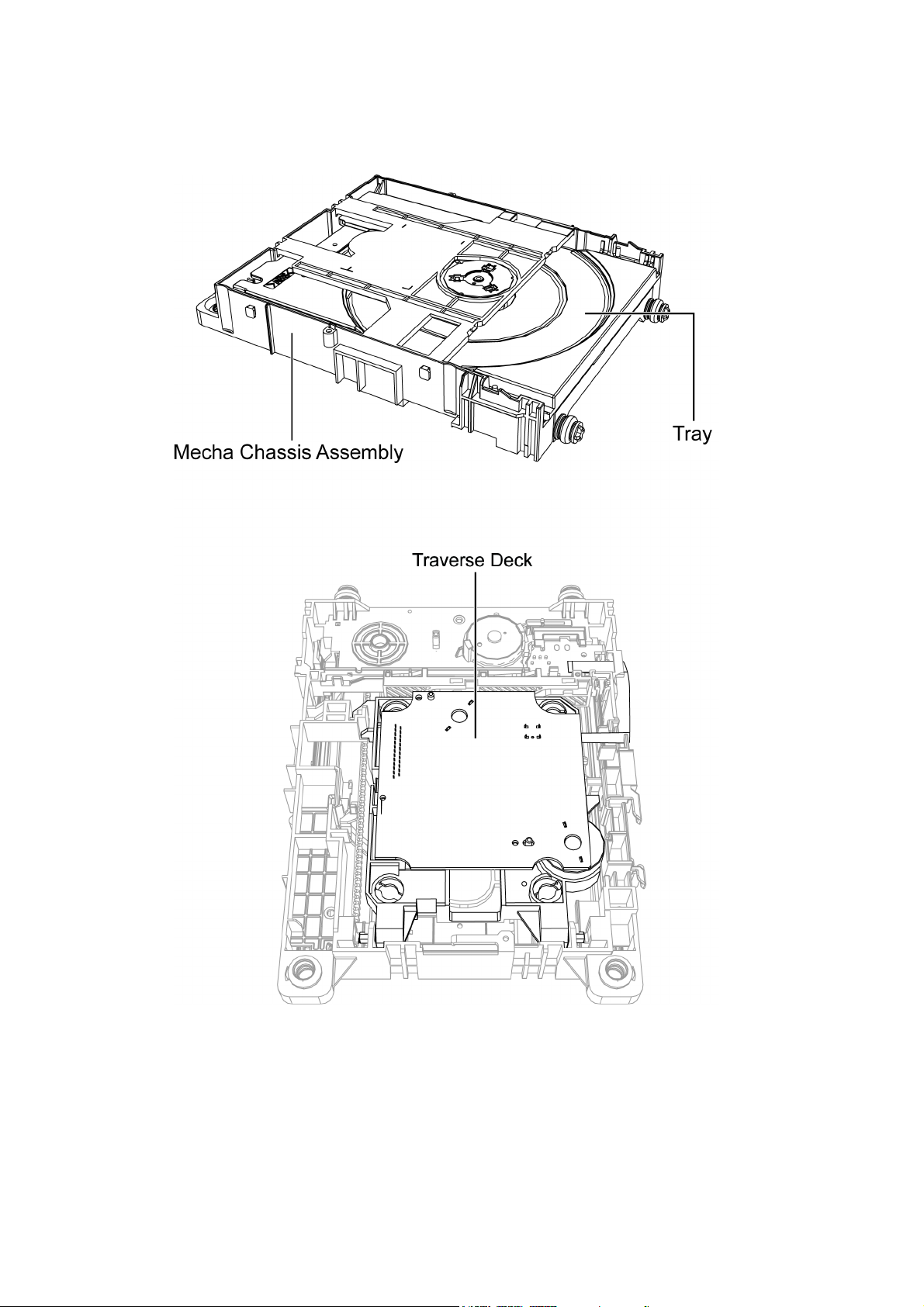
1 Mechanism Overview (BRS1C)
BRS1 mechanism is a single tray mechanism used for CD/DVD models.
1.1. Mecha Chassis Assembly / Tray / Traverse Deck
2
Page 3
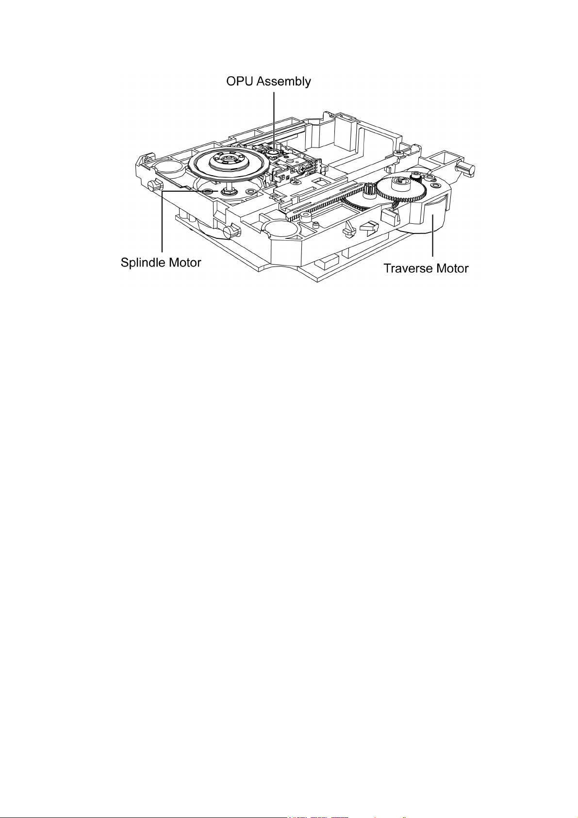
1.2. Traverse Motor
3
Page 4

2Warning
2.1. Prevention of Electro Static Discharge (ESD) to Electrostatically Sensitive (ES) Devices
Some semiconductor (solid state) devices can be damaged easily by static electricity. Such components commonly are called Electrostatically Sensitive (ES) Devices. Examples of typical ES devices are integrated circuits and some field-effect transistors and
semiconductor “chip” components. The following techniques should be used to help reduce the incidence of component damage
caused by electrostatic discharge (ESD).
1. Immediately before handling any semiconductor component or semiconductor-equipped assembly, drain off any ESD on your
body by touching a known earth ground. Alternatively, obtain and wear a commercially available discharging ESD wrist strap,
which should be removed for potential shock reasons prior to applying power to the unit under test.
2. After removing an electrical assembly equipped with ES devices, place the assembly on a conductive surface such as aluminium foil, to prevent electrostatic charge build up or exposure of the assembly.
3. Use only a grounded-tip soldering iron to solder or unsolder ES devices.
4. Use only an anti-static solder remover device. Some solder removal devices not classified as “anti-static (ESD protected)” can
generate electrical charge sufficient to damage ES devices.
5. Do not use freon-propelled chemicals. These can generate electrical charges sufficient to damage ES devices.
6. Do not remove a replacement ES device from its protective package until immediately before you are ready to install it. (Most
replacement ES devices are packaged with leads electrically shorted together by conductive foam, aluminium foil or comparable conductive material).
7. Immediately before removing the protective material from the leads of a replacement ES device, touch the protective material
to the chassis or circuit assembly into which the device will be installed.
Caution :
Be sure no power is applied to the chassis or circuit, and observe all other safety precautions.
8. Minimize bodily motions when handling unpackaged replacement ES devices. (Otherwise harmless motion such as the
brushing together of your clothes fabric or the lifting of your foot from a carpeted floor can generate static electricity (ESD) sufficient to damage an ES device).
4
Page 5
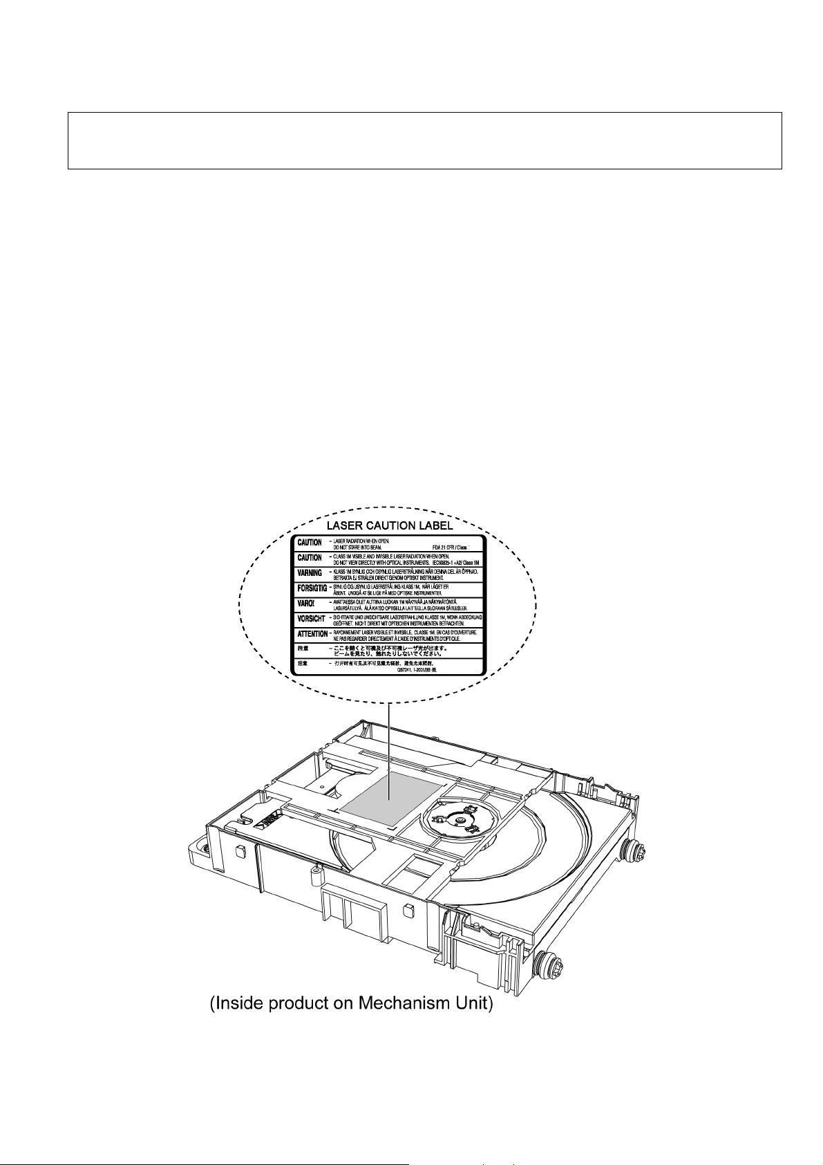
2.2. Precaution of Laser Diode
CAUTION!
THIS PRODUCT UTILIZES A LASER.
USE OF CONTROLS OR ADJUSTMENTS OR PERFORMANCE OF PROCEDURES OTHER THAN THOSE SPECIFIED HEREIN MAY RESULT
IN HAZARDOUS RADIATION EXPOSURE.
Caution:
This product utilizes a laser diode with the unit turned "on", invisible laser radiation is emitted from the pickup lens.
Wavelength: 655 nm (DVD)/790 nm (CD)
Maximum output radiation power from pickup: 100 μW/VDE
Laser radiation from the pickup unit is safety level, but be sure the followings:
1. Do not disassemble the pickup unit, since radiation from exposed laser diode is dangerous.
2. Do not adjust the variable resistor on the pickup unit. It was already adjusted.
3. Do not look at the focus lens using optical instruments.
4. Recommend not to look at pickup lens for a long time.
ACHTUNG :
Dieses Produkt enthält eine Laserdiode. Im eingeschalteten Zustand wird unsichtbare Laserstrahlung von der Lasereinheitadgestrahit.
Wellenlänge : 655 nm (DVD)/790 nm (CD)
Maximale Strahlungsleistung der Lasereinheit :100 μW/VDE
Die Strahlung an der Lasereinheit ist ungefährlich, wenn folgende Punkte beachtet werden:
1. Die Lasereinheit nicht zerlegen, da die Strahlung an der freigelegten Laserdiode gefährlich ist.
2. Den werkseitig justierten Einstellregler der Lasereinhit nicht verstellen.
3. Nicht mit optischen Instrumenten in die Fokussierlinse blicken.
4. Nicht über längere Zeit in die Fokussierlinse blicken.
5
Page 6

2.3. Service caution based on Legal restrictions
2.3.1. General description about Lead Free Solder (PbF)
The lead free solder has been used in the mounting process of all electrical components on the printed circuit boards used for this
equipment in considering the globally environmental conservation.
The normal solder is the alloy of tin (Sn) and lead (Pb). On the other hand, the lead free solder is the alloy mainly consists of tin
(Sn), silver (Ag) and Copper (Cu), and the melting point of the lead free solder is higher approx.30 degrees C (86°F) more than that
of the normal solder.
Definition of PCB Lead Free Solder being used
The letter of “PbF” is printed either foil side or components side on the PCB using the lead free solder.
(See right figure)
Service caution for repair work using Lead Free Solder (PbF)
• The lead free solder has to be used when repairing the equipment for which the lead free solder is used.
(Definition: The letter of “PbF” is printed on the PCB using the lead free solder.)
• To put lead free solder, it should be well molten and mixed with the original lead free solder.
• Remove the remaining lead free solder on the PCB cleanly for soldering of the new IC.
• Since the melting point of the lead free solder is higher than that of the normal lead solder, it takes the longer time to melt the
lead free solder.
• Use the soldering iron (more than 70W) equipped with the temperature control after setting the temperature at 350±30 degrees
C (662±86°F).
Recommended Lead Free Solder (Service Parts Route.)
• The following 3 types of lead free solder are available through the service parts route.
RFKZ03D01K-----------(0.3mm 100g Reel)
RFKZ06D01K-----------(0.6mm 100g Reel)
RFKZ10D01K-----------(1.0mm 100g Reel)
Note
* Ingredient: Tin (Sn), 96.5%, Silver (Ag) 3.0%, Copper (Cu) 0.5%, Cobalt (Co) / Germanium (Ge) 0.1 to 0.3%
6
Page 7
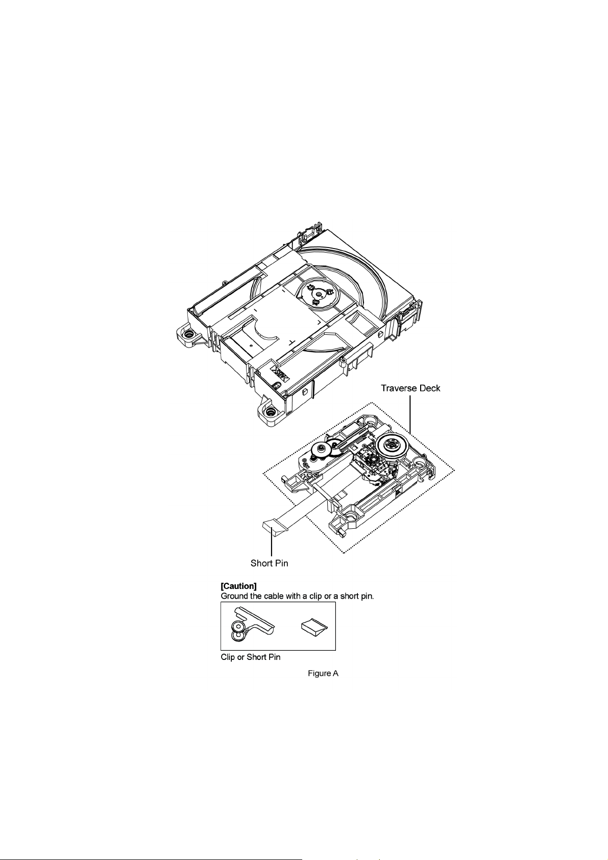
2.4. Handling Precaution for Traverse Deck
The laser diode in the optical pickup unit may break down due to static electricity of clothes or human body. Special care must be
taken avoid caution to electrostatic breakdown when servicing and handling the laser diode in the traverse deck.
2.4.1. Cautions to Be Taken in Handling the Optical Pickup Unit
The laser diode in the optical pickup unit may be damaged due to electrostatic discharge generating from clothes or human body.
Special care must be taken avoid caution to electrostatic discharge damage when servicing the laser diode.
1. Do not give a considerable shock to the optical pickup unit as it has an extremely high-precise structure.
2. To prevent the laser diode from the electrostatic discharge damage, the flexible cable of the optical pickup unit removed
should be short-circuited with a short pin or a clip.
3. The flexible cable may be cut off if an excessive force is applied to it. Use caution when handling the flexible cable.
4. The antistatic FPC is connected to the new optical pickup unit. After replacing the optical pickup unit and connecting the flexible cable, cut off the antistatic FPC.
7
Page 8
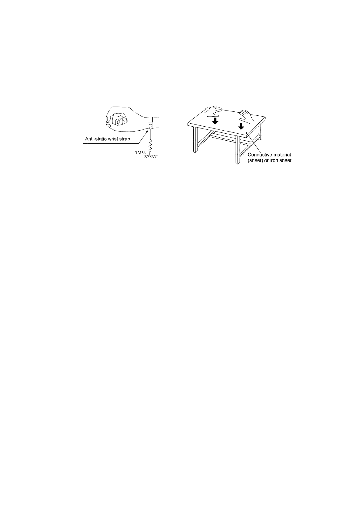
2.4.2. Grounding for electrostatic breakdown prevention
Some devices such as the CD player use the optical pickup (laser diode) and the optical pickup will be damaged by static electricity
in the working environment. Proceed servicing works under the working environment where grounding works is completed.
2.4.2.1. Worktable grounding
1. Put a conductive material (sheet) or iron sheet on the area where the optical pickup is placed, and ground the sheet.
2.4.2.2. Human body grounding
1. Use the anti-static wrist strap to discharge the static electricity form your body (Figure 2).
Figure 2
8
Page 9
3 Mechanism Operation
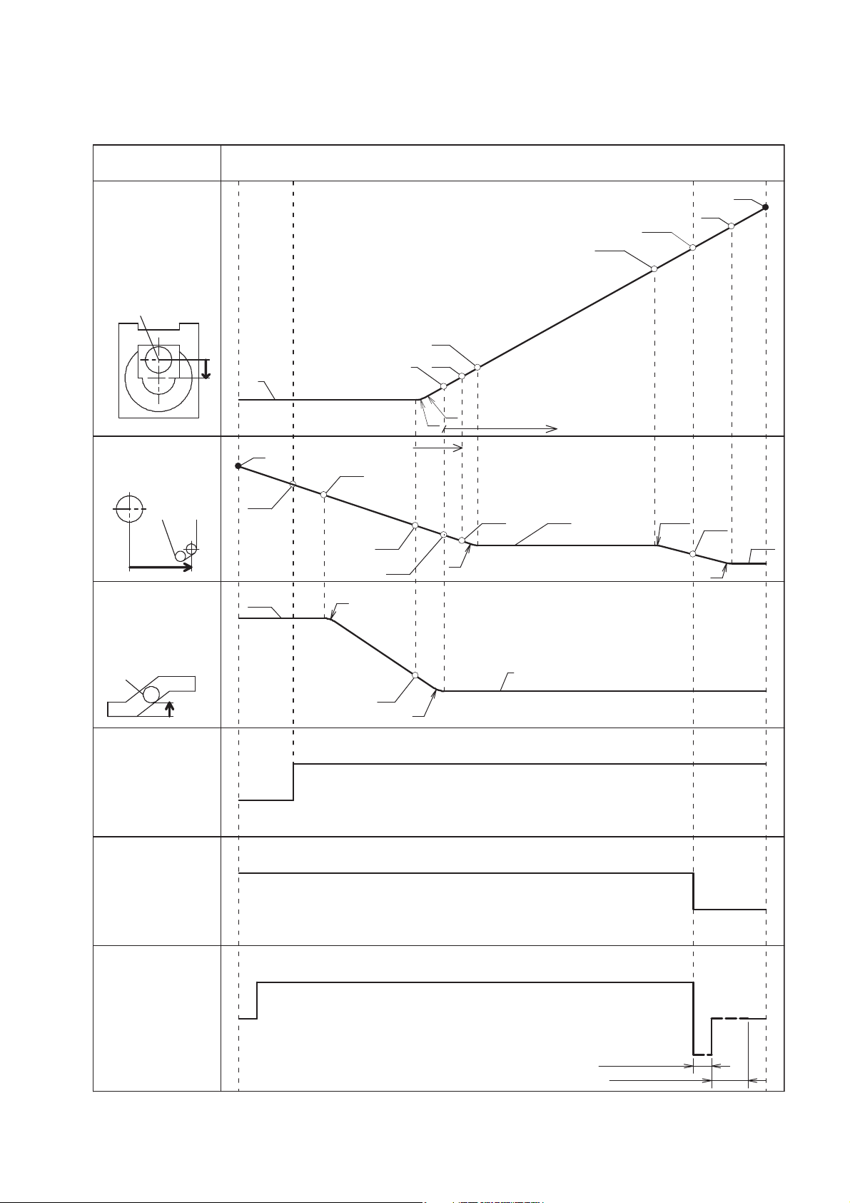
Tray
TRV Slide Plate
TRV Base
Close SW
Open SW
Loading Motor
state
Close
SW ON
stopper
Open
SW ON
stopper
T.S.P. Tray
51.6
55
135
49.9
41.7
R4
R3
7.71
0
0
R8
R4
R3
2.1
38.6
9.2
31.9
129.2
31.1
126.9
R8.45
R3
30.1
132
Reverse brake
Short brake
H
L
H
L
CW
CCW
TT center
TT center
Front boss
33.4
T.S.P. Rack engage
Tray Rack engage
2 6.9
3.1. Close/Open Operation
9
Page 10
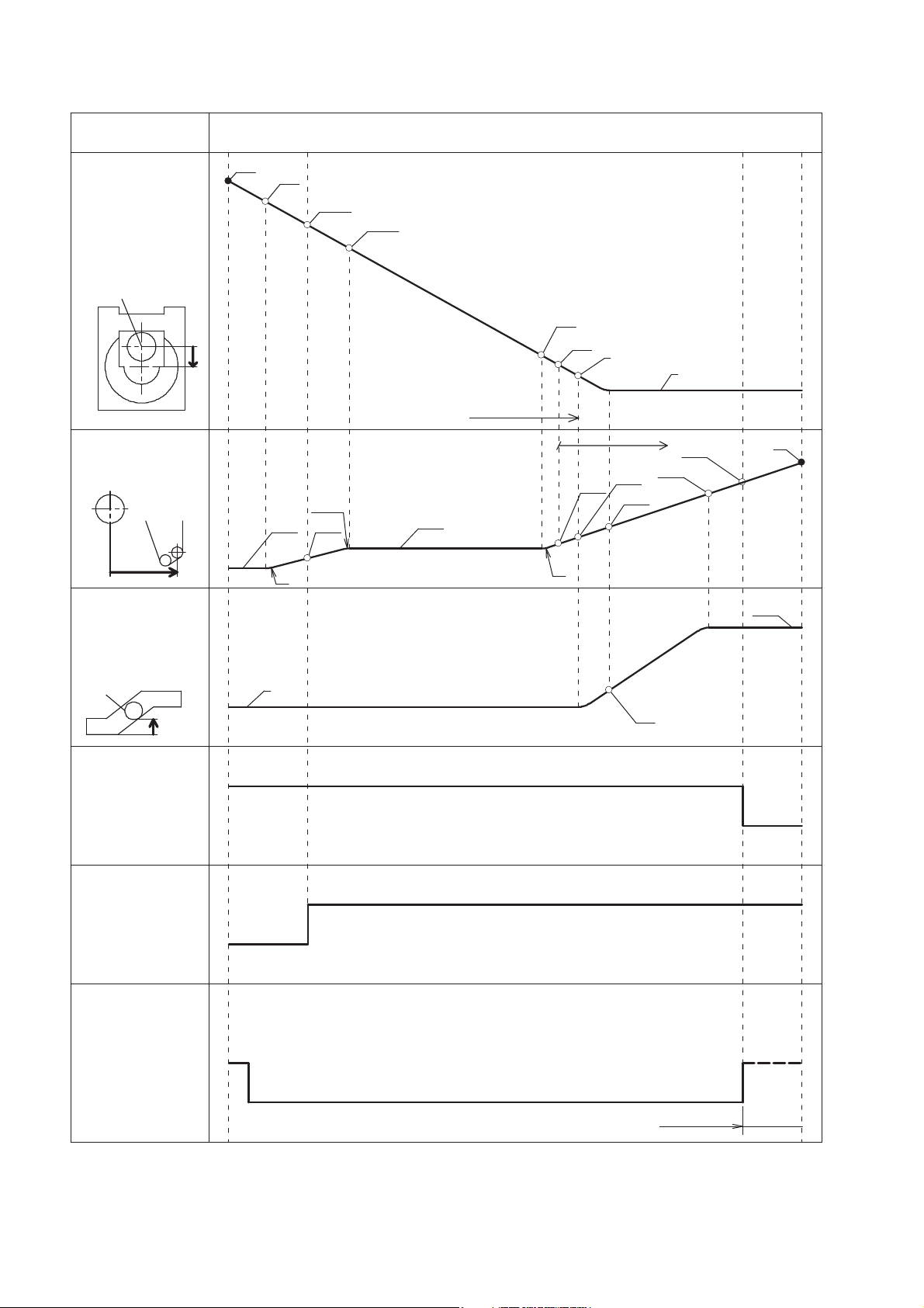
3.2. Open/Close Operation
state
Tray
TT center
TRV Slide Plate
TT center
stopper
135
132
30.1
R3
Open
SW ON
R8.45
129.2
31.1
126.9
31.9
Tray Rack engage
8.6
R3
6.8
2
T.S.P. Rack engage
33.8
38.6
41.7
49.9
0
51.6
Close
SW ON
T.S.P.Tray
stopper
55
TRV Base
Front boss
Close SW
Open SW
7.71
0
2.1
H
L
H
L
CW
Loading Motor
CCW
Short brake
10
Page 11
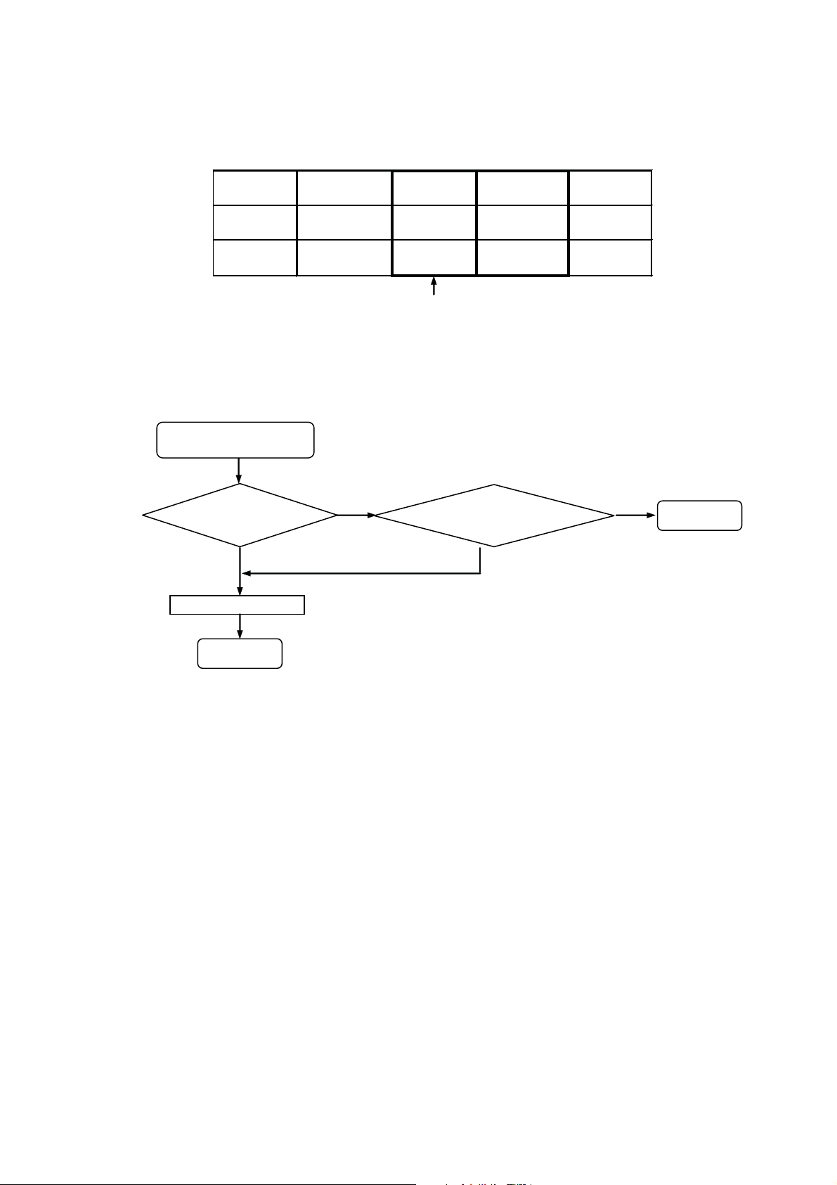
3.3. Initialization
Condition for Initialization Processing:
Table 1
LOAD-SW LD-MOTOR INNER-SW TRV-MOTOR
LC - H CCW
LO CCW H CCW
LC - L CW
LO CCW L CW
Main Consideration
Condition 2
Condition 1
Initialization
Decision Processing
No need initialization
Backup
Memory cleared?
N
Y
EXIT
INNER-SW= L ?
LOAD-SW = LC?
N
Y
EXIT
Initialization Processing
During the power-up of main unit (using BRS1C mechanism), the state of switches is sensored by the micro-p IC and the traverse
motor is adjusted accordingly.
Note : Refer to Table 1 for the initialization process.
3.3.1. When there is no Initialization
11
Page 12
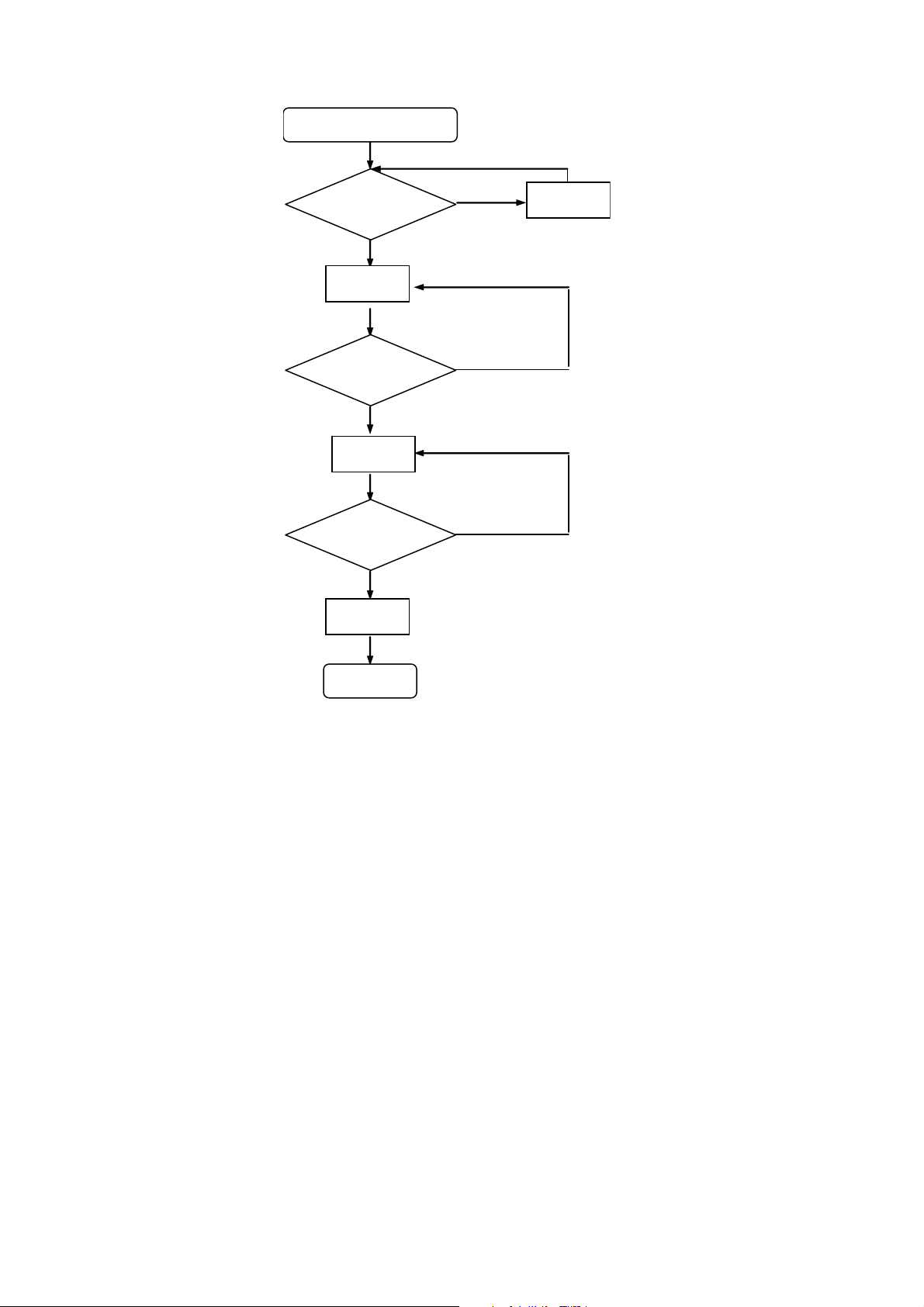
3.3.2. When there is Initialization
Initialization Processing
INNER-SW
= L ?
N
Y
TRV-MOTOR
CCW
TRV-MOTOR
CW
INNER-SW
= H ?
N
Y
TRV-MOTOR
CCW
INNER-SW
= L ?
N
Y
TRV-MOTOR
Brake
EXIT
12
Page 13
3.4. Fail Safe Mode
Fail Safe specification
Close position
move to Open position→ Open position move to Close position→ Close position
Locked at
Motor CCW
condition
( in the case
motor can turn
CW)
Moror CCW for 5sec
(Time out)
↓
Motor CW to Open position
Locked at
Motor CCW
condition
( in the case
motor can not
turn CW)
Moror CCW for 5sec (TO)
↓
Motor CW for 5sec (TO)
↓
Loop
↓
ERROR stop (at 4th TO)
Locked at
Motor CW
condition
( in the case
motor can turn
CCW)
Moror CW for 5sec
(Time out)
↓
Motor CCW to Close
position
Locked at
Motor CW
condition
( in the case
motor can not
turn CCW)
Moror CW for 5sec (TO)
↓
Motor CCW for 5sec (TO)
↓
Loop
↓
ERROR stop (at 4th TO)
Fail Safe
state
Table 2
* Fail safe is a function for recovery of tray movement if mechanism cannot carry out tray open or close within a specified time.
Below are the fail safe specification at each position. Refer to table 2.
13
Page 14

4 Disassembly and Assembly Instructions
Caution Note:
• This section describes the disassembly and/or assembly procedures for all major printed circuit boards & main components for the unit. (You may refer to the section of “Main components and P.C.B Locations” as described in the service
manual)
• Before carrying out the disassembly process, please ensure all the safety precautions & procedures are followed.
• During the disassembly and/or assembly process, please handle with care as there may be chassis components with
sharp edges.
• Avoid touching heatsinks due to its high temperature after prolong use. (See caution as described below)
• During disassembly and assembly, please ensure proper service tools, equipments or jigs is being used.
• During replacement of component parts, please refer to the section of “Replacement Parts List” as described in the service manual.
• Select items from the following indexes when disassembly or replacement are required.
• Disassembly of Tray
• Disassembly of Traverse Deck
• Disassembly of Traverse Slide Plate
• Disassembly of Belt, Pulley Gear & Driver Gear
• Disassembly of Loading P.C.B.
• Disassembly of Loading Motor
14
Page 15

4.1. Flow Chart
4.1.1. Disassembly flow chart
Below describes the disassembly flow for the mechanism.
4.1.2. Assembly flow chart
Below describes the assembly flow for the mechanism.
15
Page 16

4.2. Disassembling Instructions
Caution : Refer to 2.4 “Handling Precaution for Traverse
Deck” to prevent static damage to the Optical Pickup unit
4.2.1. Disassembly of Tray
Step 1 : Use a pin to slide the Traverse Slide Plate until it come
to a stop. The tray will open slightly.
Step 3 : Release the catches & remove the tray.
Step 2 : Gently push out the tray until it is fully extended.
16
Page 17

4.2.2. Disassembly of Traverse Deck
• Refer to “Disassembly of Tray”
Note :
1. When the optical pickup unit is defective, the overall
traverse deck needs replacement.
2. Please note that appropriate actions need to be taken to
prevent static damage.
Step 1 : Release the guide as shown & slide the Traverse Slide
Plate to the end.
Step 2 : Detach 5P FFC at the connector (CN7003) on CD
Servo P.C.B..
Step 3 : Gently lift up the Traverse Deck by approximately 45°.
Step 4 : Remove the Traverse Deck as arrow shown.
17
Page 18

Caution : Avoid touching the surface of the Optical Pickup
Unit.
4.2.3. Disassembly of Traverse Slide Plate
• Refer to “Disassembly of Tray”
• Refer to “Disassembly of Traverse Deck”
Step 1 : Pull forward catches as shown to release Traverse
Slide Plate.
Step 2 : Remove the Traverse Slide Plate in order of
sequences (1) to (2) as shown.
18
Page 19

4.2.4. Disassembly of Belt, Pulley Gear & Driver Gear
• Refer to “Disassembly of Tray”
• Refer to “Disassembly of Traverse Deck”
• Refer to “Disassembly of Traverse Slide Plate”
• Disassembly of Belt
Step 1 : Remove the Belt as shown.
Step 3 : Remove the Pulley Gear as shown.
• Disassembly of Driver Gear
Step 4 : Remove the Driver Gear as shown.
• Disassembly of Pulley Gear
Step 2 : Use a screwdriver to release the catches and push
down the Pulley Gear in order of sequences (1) to (2).
19
Page 20

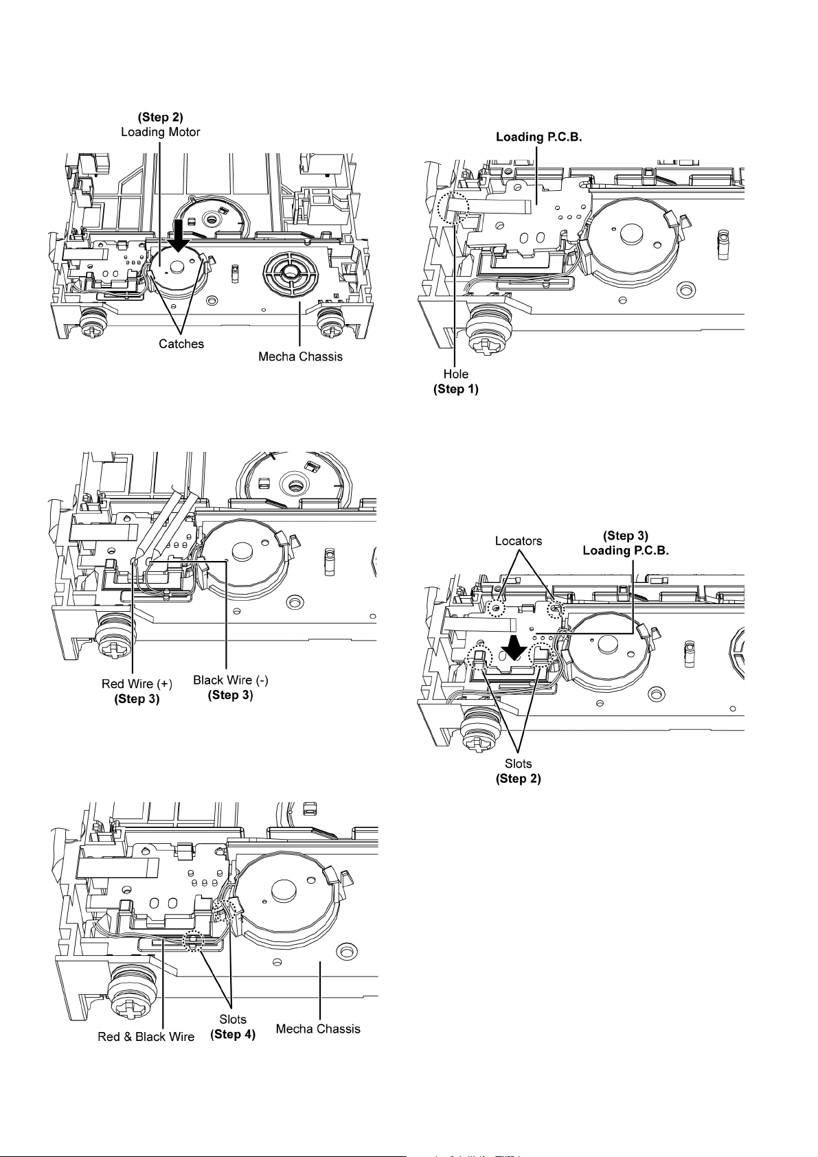
4.2.5. Disassembly of Loading P.C.B.
• Refer to “Disassembly of Tray”
• Refer to “Disassembly of Traverse Deck”
• Refer to “Disassembly of Traverse Slide Plate”
• Refer to “Disassembly of Belt”
Step 1 : Desolder pins of the Red Wire (+) & Black Wire (-) on
the solder side of Loading P.C.B..
Step 3 : Release the FFC from the hole of Mecha Chassis.
Step 4 : Release the catch and lift up the Loading P.C.B. as
shown.
Step 5 : Remove Loading P.C.B..
Step 2 : Release the Red Wire and Black Wire from the slot.
20
Page 21

4.2.6. Disassembly of Loading Motor
• Refer to “Disassembly of Tray”
• Refer to “Disassembly of Traverse Deck”
• Refer to “Disassembly of Traverse Slide Plate”
• Refer to “Disassembly of Belt”
• Follow the (Step 1) of item 4.2.5”
Step 1 : Release catches as shown.
4.3. Assembly Instructions
4.3.1. Assembling of Loading Motor
Step 1 : Fix the Loading Motor as shown.
Caution : Ensure Loading Motor wire is align with Mecha
Chassis wire slot & seated properly on the mecha chassis.
Step 2 : Remove the Loading Motor as shown.
21
Page 22
Step 2 : Press the Loading motor as shown ensure. A “click”
sound is heard when the Loading Motor is fully catched.
Step 3 : Solder the Red Wire (+) & Black Wire (-) onto Loading
P. C .B . .
4.3.2. Assembling of Loading P.C.B.
Step 1 : Insert the FFC through the hole of Mecha Chassis.
Step 2 : Place the Loading P.C.B. underneath slots.
Caution : Ensure the Loading P.C.B. is properly seated
onto the 2 locators.
Step 3 : Press down the Loading P.C.B.. A “click” sound is
heard when the Loading P.C.B. is fully catched.
Step 4 : Dressed the Red Wire & Black Wire as shown.
22
Page 23

Step 4 : Solder the Red Wire (+) & Black Wire (-) onto the
Loading P.C.B..
Step 5 : Dressed the Red Wire & Black Wire into the slot of
Mecha Chassis.
4.3.3. Assembling of Driver Gear, Pulley Gear & Belt
Step 1 : Fix the Driver Gear into the Boss as shown.
Step 2 : Fix the Pulley Gear into the boss as shown, press
downwards A “click” sound is heard when the pulley gear is
properly fixed.
23
Page 24

Step 3 : Fix Belt.
4.3.4. Assembling of Traverse Slide Plate
Step 1 : Place the Traverse Slide Plate into the Mecha Chassis
as shown.
Step 2 : Slide the Traverse Slide Plate to the end as shown &
flip over the Mecha Chassis.
24
Page 25

Step 3 : Press the Traverse Slide Plate and make sure it is fully
catched onto the Mecha Chassis.
4.3.5. Assembling of Traverse Deck
Step 1 : Release the guide as shown & slide the Traverse Slide
Plate to the end.
25
Page 26
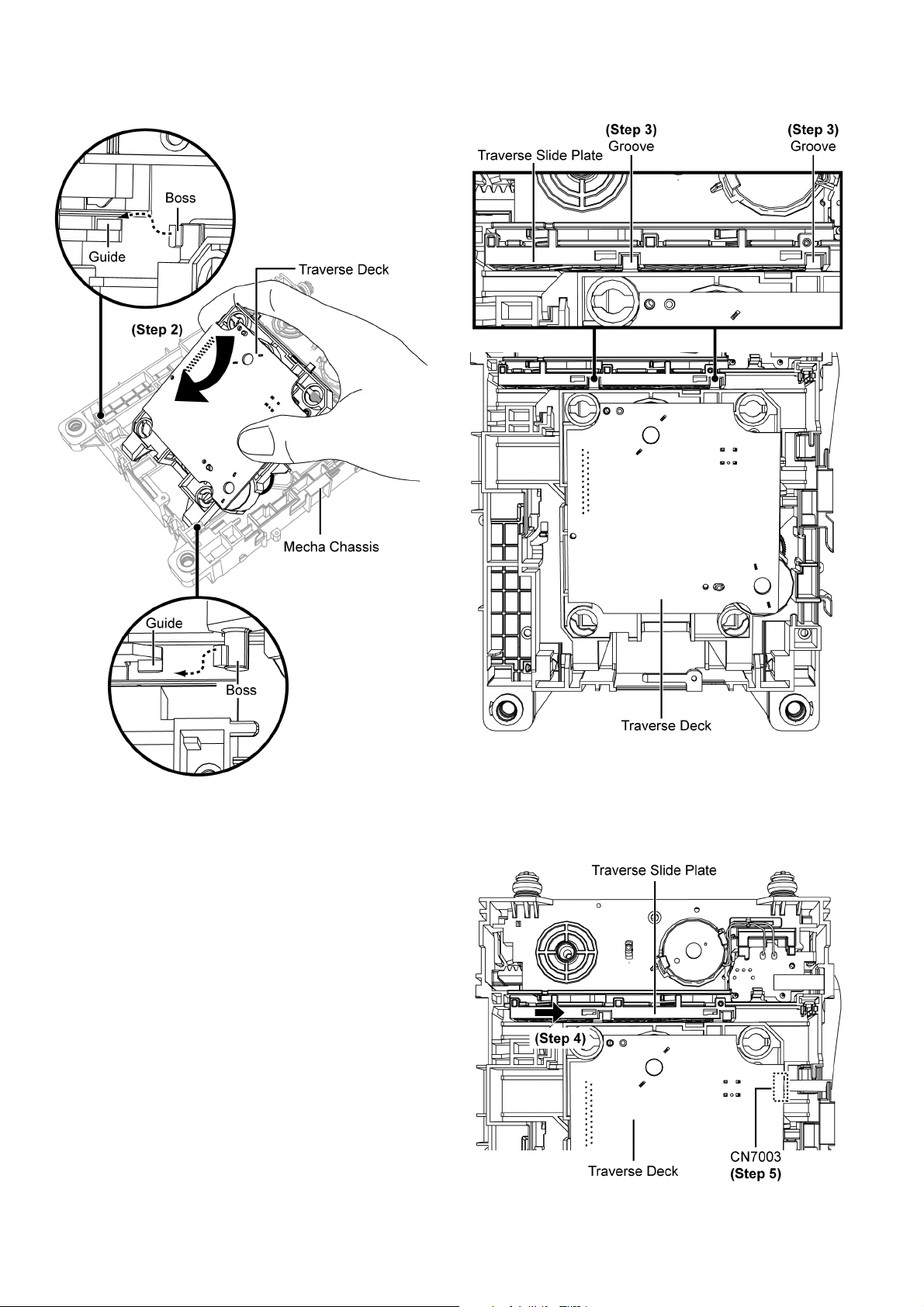
Step 2 : Insert the Traverse Deck into the bosses at approximately 45° into the mecha chassis as arrow shown.
Step 3 : Insert the Traverse Deck into the grooves of the
Traverse Slide Plate.
Step 4 : Slide Traverse Slide Plate as arrow shown to lock the
Traverse Deck.
Step 5 : Connect 5P FFC at the connector (CN7003) on CD
Servo P.C.B..
26
Page 27

4.3.6. Assembling of Tray
Step 1 : Slide the Traverse Slide Plate until it stop at the Guide.
Step 2 : Insert the Tray into the Guide Rails as picture shown.
Step 3 : Align the guides of the Traverse Slide Plate, with the
groove of the tray.
27
Page 28

Step 4 : Gently push in the tray until it is fully close.
Caution : Do not use strong force during pushing of the
tray. if the tray does not move Repeat Step 1 to Step 3 of
this section.
28
Page 29
5Reliability
Purpose: To test the BRS1 mechanism unit operation by using the Reliability P.C.B. before installation into the main unit.
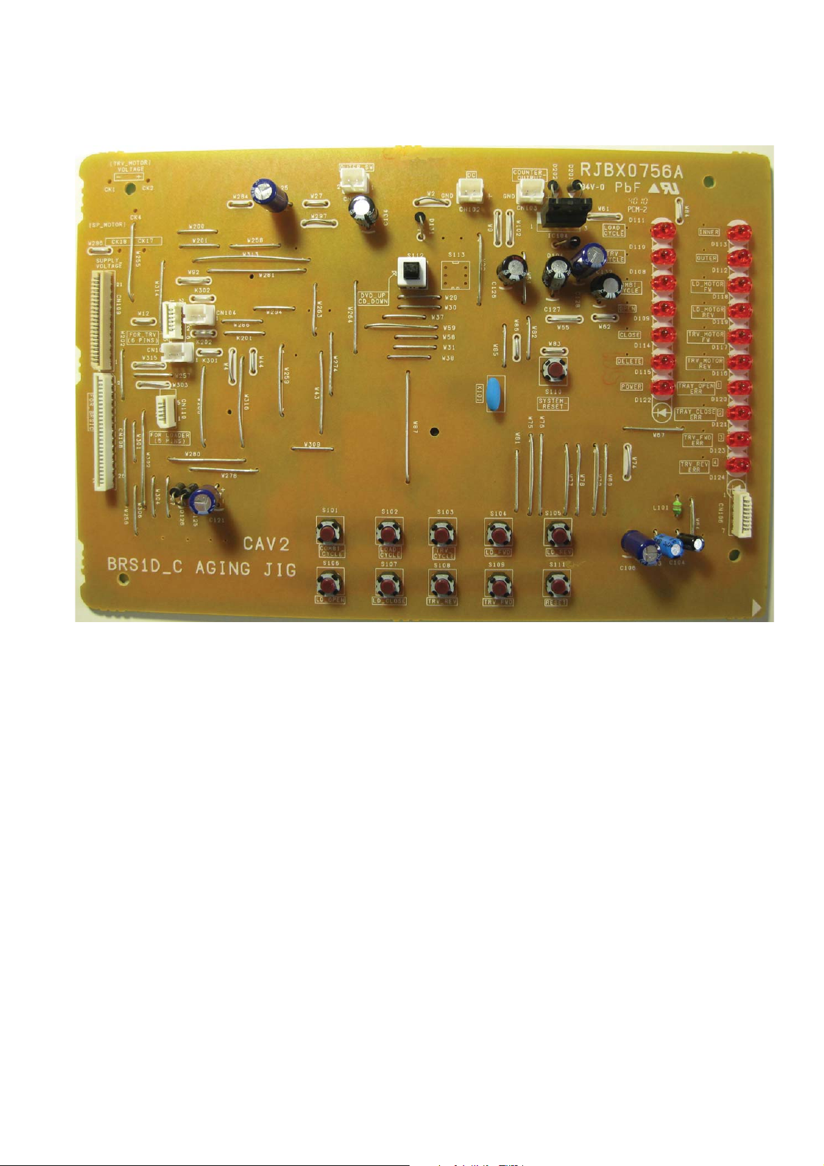
5.1. Diagram of Reliability P.C.B.
29
Page 30

5.2. Functions Descriptions
Function Name Function Description
Tray - Open When press [LD_OPEN], LD Motor drive until detect LOAD-SW = LO
Tray - Close When press [LD_CLOSE], LD Motor drive until detect LOAD-SW = LC
Trv - Forward When press [TRV FW ], Trv Motor drive until detect INNER-SW = L
Trv - Reverse W hen press [TRV REV], Trv Motor drive until detect OUTER-SW = L
LD-Motor -FW When press [LD-FWD] and hold, LD Motor turns CCW until button release.
LD-Motor -Rev W hen press [LD-REV] and hold, LD Motor turns CCW until button release.
RESET When press [RESET], the mechanism will go through the INITIALIZATION process.
Retry Mode When press [Retry Mode]. The tray retry function will activated
Ageing Mode Ageing Mode Description
Loading Cycle
tray open & close operation.
Traverse Cycle When press [Trv Cycle], mechanismwill be in continuos mode for
OPU forward & reverse operation.
Combine Cycle When press [Combi Cycle], mechanismwill carry out full operation from
OPU at outer position - Tray fully opened & vice versa in continuos mode.
** The above ageingmode will stop when user press [RESET] or switch OFF power on this board.
5.3. Ageing MODE Description
When press [Load Cycle], mechanismwill be in continuos mode for
30
Page 31
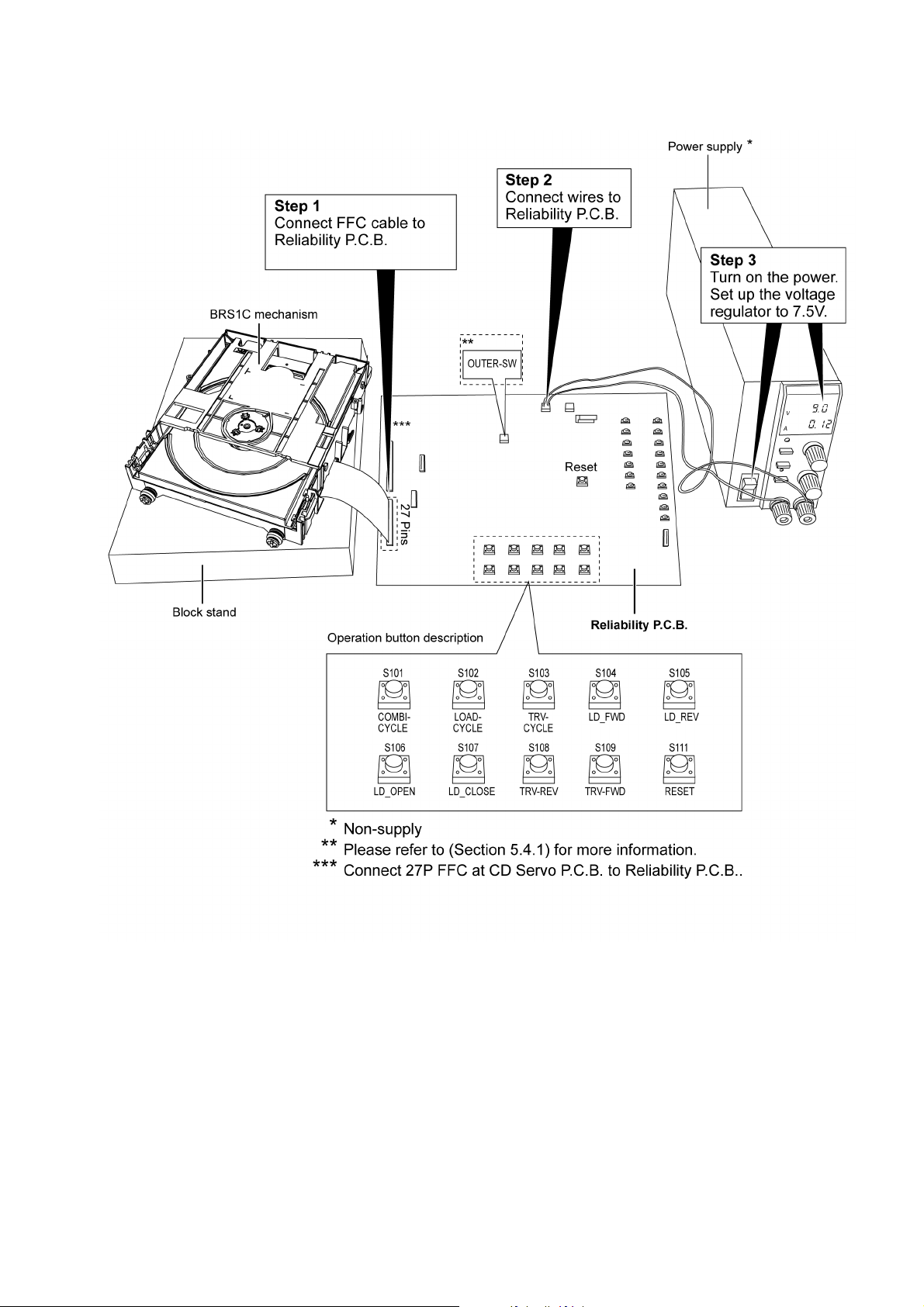
5.4. Reliability Setup Connection
Below diagram shows the set-up necessary to carry out the reliability of mechanism
31
Page 32

5.4.1. Location of Outer-Switch
• Refer following for the suggested location for the mounting of the outer-switch (Part No. K0L1BA000158)
32
Page 33

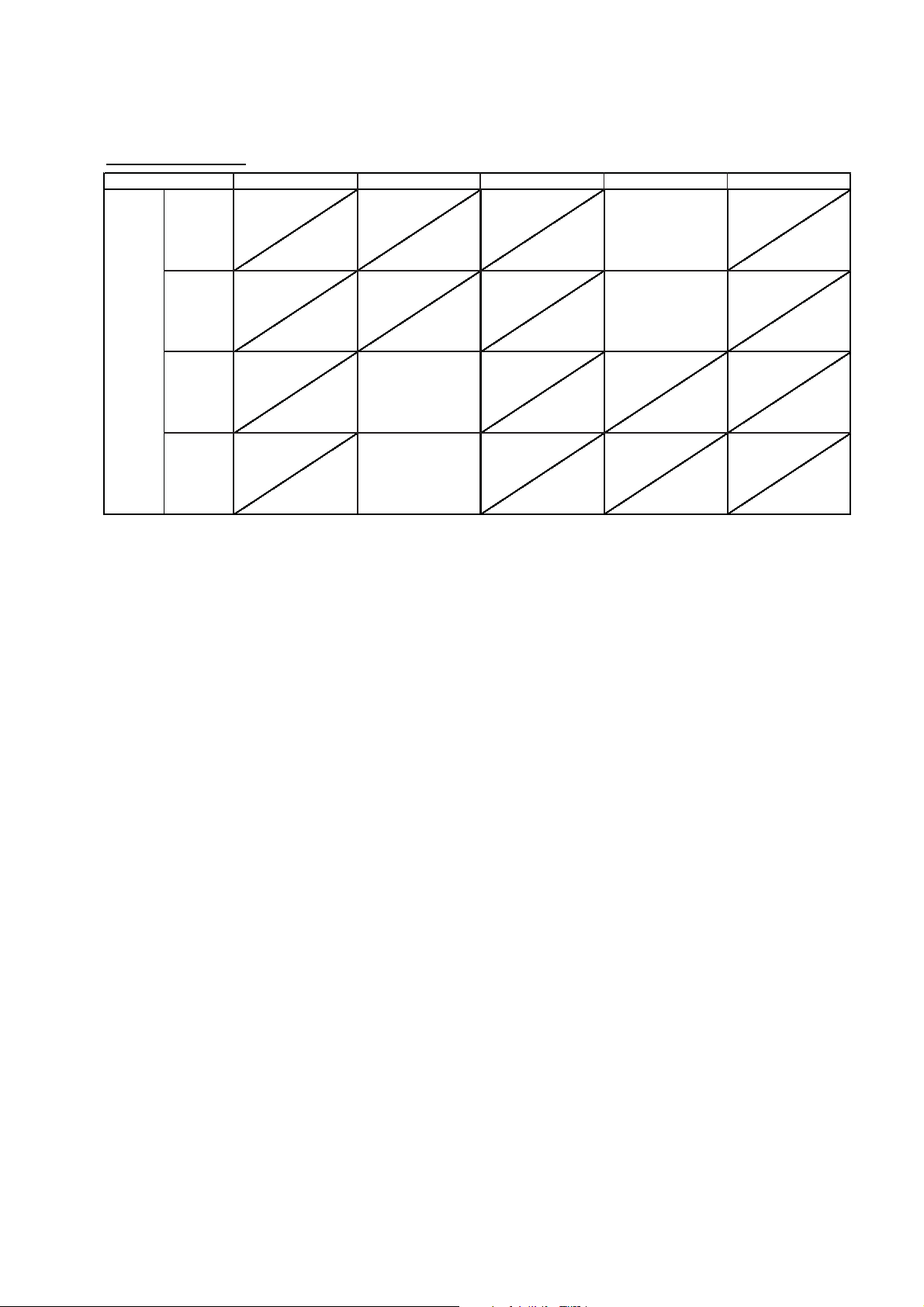
5.5. Jig’s Flow Diagram
ahceMnoitarepOnottuB
mode LD INNER OUTER
LD_Open [Normal Operation]
S106
S107
S104
S105
S101
S102
S103
HLOLnoitisopnepOdnaWCsnrutrotomDL
stop when LOAD-SW = Signal change from LC-->LO
LD_Close [Normal Oper
ation]
HLCLnoitisoPesolCdnaWCCsnrutrotomDL
stop when LOAD-SW = Signal change from LO-->LC
Trv FW [Normal Operation]
HLCLrennIUPOdnaWCCsnrutrotomVRT
noitiso
pL>--HmorfegnahclangiS=WS-RENNInehwspots
Trv REV [Normal Operation]
LHCLretuOUPOdnaWCsnrutrotomVRT
noitisopL>--Hmorfegnahcl
angiS=WS-RETUOnehwspots
LD-FW [Manual mode]
~~~edomlaunaMdnaWCsnrutrotomDL
WFrotomvrTnottubesaelerresunehwspo
ts
LD-REV [Manu
al mode]
~~~edomlaunaMdnaWCCsnrutrotomDL
veRrotomvrTnottubesaelerresunehwspots
Combi [Aging Mode-1]
Mechanism in continuous cycle mode of combination between Mode-1 ~ ~ ~
Loading and Tr
averse function.
Load[Aging Mode-2]
Mechanism in continuous cycle mode of Loading function. Mode-2 ~~ ~
Trv [Aging Mode-3]
Mechanism in continuous cycle mode of Traverse function. Mode-3 ~ ~ ~
Switch state
33
Page 34

5.5.1. Normal Operation, Manual, Initialization
Press [LD Open]
LOAD-SW
= LO ?
N
Y
LD-MOTOR
CW
EXIT
Tact-Sw=H-->LO
Press [Trv FW]
INNER-SW
= H ?
N
Y
TRV-MOTOR
CW
EXIT
TRV-MOTOR
CCW
INNER-SW
= L ?
N
Y
Tact-Sw=H-->L
Press [Trv Rev]
OUTER-SW
= L ?
N
Y
TRV-MOTOR
CW
EXIT
Tact-Sw=H-->L
Press [LD Close]
LOAD-SW
= LC ?
N
Y
LD-MOTOR
CCW
EXIT
Tact-Sw=H-->LC
Normal Operation , Manual , Initialization
34
Page 35

5.5.2. Aging
Press [Combi]
LOAD-SW
= LO?
N
Y
LD-MOTOR
CW
Tact-Sw=H-->L
LD-MOTOR
CCW
LOAD-SW
= LC ?
N
Y
TRV-MOTOR
CW
OUTER-SW
= L ?
N
Y
COUNTER
CNT=CNT+1
Press [Load]
LOAD-SW
= LO ?
N
Y
LD-MOTOR
CW
Tact-Sw=H-->L
LD-MOTOR
CCW
LOAD-SW
= LC ?
N
Y
COUNTER
CNT=CNT+1
Press [Trv]
OUTER-SW
= L ?
N
Y
TRV-MOTOR
CW
Tact-Sw=H-->L
TRV-MOTOR
CCW
INNER-SW
= L ?
N
Y
COUNTER
CNT=CNT+1
TRV-MOTOR
CCW
INNER-SW
= L ?
Y
35
Page 36

Press [RESET]
Refer next page of spec.
for initialization process.
Tact-Sw=H-->L
Press [LD-FW]
Tact-Sw
=H-->L (long press)
LD-MOTOR
CW
Release [FW]
key?
EXIT
Y
N
LOAD-SW
= LO ?
N
Press [LD-Rev]
Tact-Sw
=H-->L (long press)
LD-MOTOR
CCW
Release [Rev]
key?
EXIT
Y
N
OUTER-SW
= L ?
N
Y
36
Page 37

6 Exploded View and Replacement Parts List
B
B
B
B
B
B
B
B
B
B
B
B
B
B
B
B
B
B
B
B
B
B
B
A
A
A
A
A
A
A
A
* (CD SERVO P.C.B.)
312
312
311
311
309-1
309
308
BOTTOM VIEW
SIDE VIEW
SIDE VIEW
SIDE VIEW
SIDE VIEW
SIDE VIEW
SIDE VIEW
SIDE VIEW
SIDE VIEW
SIDE VIEW
TOP VIEW
TOP VIEW
BOTTOM VIEW
307
306
305
FRONT VIEW
BACK VIEW
304
SIDE VIEW
TOP VIEW
303
302
* TRAVERSE ASS’Y
NOTE: "*" PART IS NOT SUPPLIED.
a
a
HANARL
GREASE
VZG0282
VZG0363
PART NUMBER
A
B
1
2
3
4
5
6
7
8
9
A
B
C
D
E
F
G
H
10 11 12 13
BRS1C
CD LOADING MECHANISM DRAWINGS
6.1. Exploded View and Mechanical replacement Parts List
6.1.1. Cabinet Parts Location
37
Page 38

38
Page 39
6.1.2. Mechanical Replacement Parts List
Safety Ref. No. Part No. Part Name &
302 RDG0650 DRIVE GEAR 1
303 RDG0651 PULLEY GEAR 1
304 RMM0304 TRAVERSE SLIDE
305 RXQ1949 LOADING MOTOR
306 VMG1720 BELT 1
307 RXQX1055 TRAY ASS’Y 1
308 RFKJMCC5602A MECHA CHASSIS
309 RFKBX0926 LOADING P.C.B 1
309-1 K0L1CB000004 SW LOADING 1
311 RMGX1004-B FRONT DAMPER 2
312 RMGX0053-R REAR DAMPER 2
Description
BRS1 MECHANISM
PLATE
ASS’Y
ASS’Y
Qty Remarks
1
1
1
IPSG1102
39
 Loading...