

Panasonic bb-hcs301a Operation Manual
Getting Started
UDIO
VIDEO
PO
WER
IN
OUT
IN
OUT
IN
OUT
UDIO
I/O
VIDEO
12
IN
D
C
IN
IN
AU
D
IO
UDIOV
ID
E
O
VIDEO
POPOW
E
R
WER
ININ
O
U
T
OUT
ININ
OUTOUT
NIN
OUTOUT
AU
D
IO
UDIO
I/OI/O
V
ID
E
O
VIDEO
12
V
UDIO
VIDEO
PO
WER
IN
OUT
IN
OUT
OUT
UDIO
I/O
VIDEO
12
IN
DC IN
IN
AUDIOUDIO
VIDEOVIDEO
POPOWERWER
IN
OUTOUT
ININ
OUTOUT
O
U
T
OUT
AUDIOUDIO
I/O
VIDEOVIDEO
12
V
UDIO
VIDEO
PO
WER
IN
OUT
OUT
OUT
UDIO
I/O
VIDEO
IN
AUDIO
VIDEO
POWER
IN
OUT
IN
OUT
IN
OUT
AUDIO
I/OI/O
VIDEO
12
V
12
UDIO
VIDEO
PO
WER
OUT
IN
OUT
IN
OUT
UDIO
VIDEO
I
N
D
C
I
N
I
N
AU
D
I
O
UDIOV
I
D
E
O
VIDEO
POPOW
E
R
WER
IN
OUTOUT
IN
OUTOUT
IN
O
U
T
OUT
AU
DIO
UDIO
I/O
V
ID
EO
VIDEO
12
V
12
Network Camera Server
•
Please read the Installation manual before using.
•
This Getting Started explains how to connect and set up this product.
See the Operating Instructions on the Setup CD-ROM for details about
the features.
Model No.
BB-HCS301A
•
If you cannot complete the setup, see the Troubleshooting manual on the
Setup CD-ROM.
Trademarks
•
Adobe, Acrobat and Reader are either registered trademarks or trademarks of Adobe Systems Incorporated in the United States and/or other countries.
•
Microsoft, Windows and ActiveX are either registered trademarks or trademarks of Microsoft Corporation in the United States and/or other countries.
•
Screen shots reprinted with permission from Microsoft Corporation.
•
All other trademarks identified herein are the property of their respective owners.
•
This software is based in part on the work of the Independent JPEG Group.
Abbreviations
•
UPnP is the abbreviation for "Universal Plug and Play".
•
"Network Camera" or the "Analog Camera connected to this product" is called "Camera" in this manual.
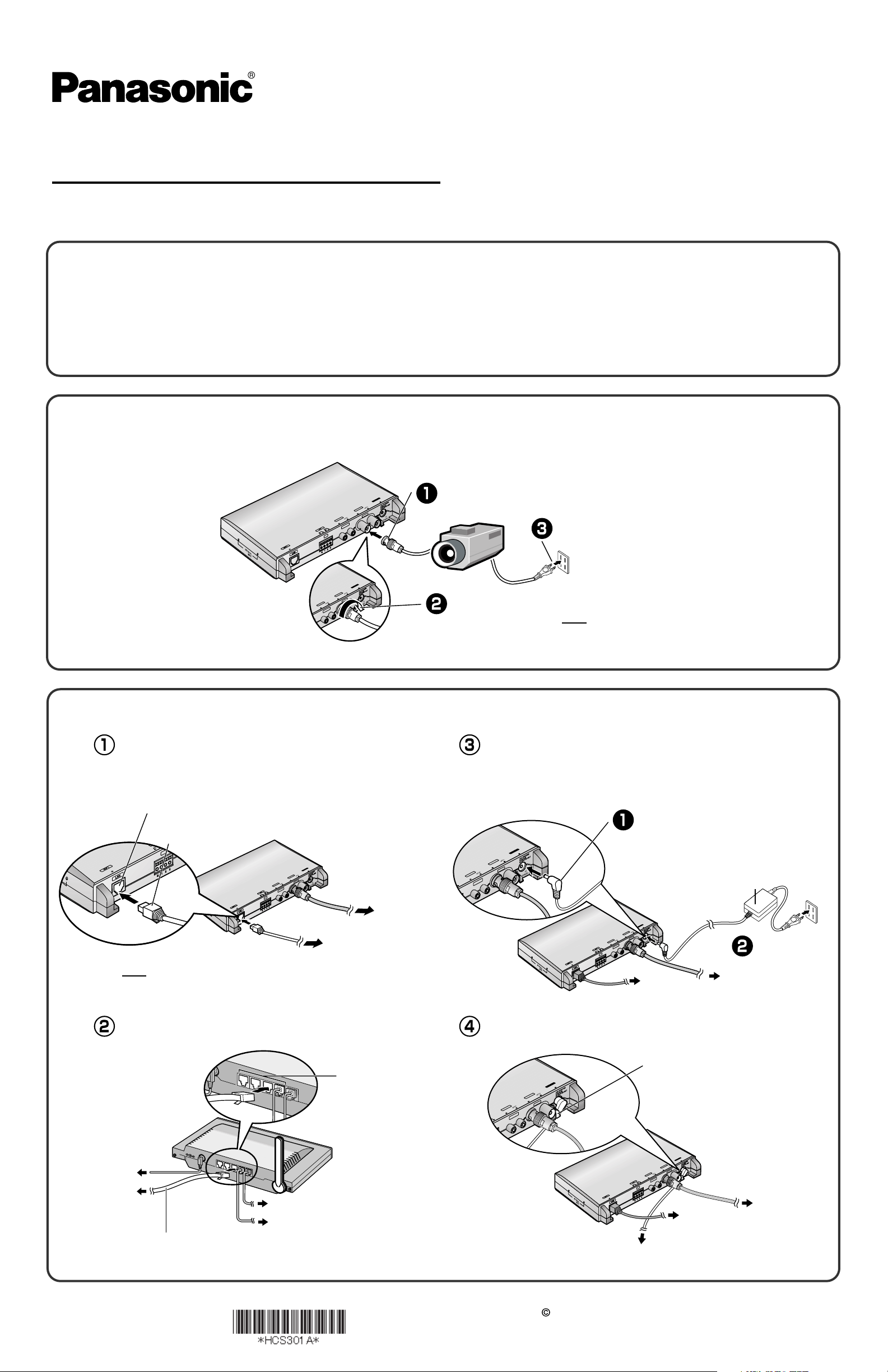
1.
2.
Connect the video cable (BNC terminal) to this product's video input terminal, and
turn the camera on.
P
O
W
D
E
C
R
IN
V
ID
E
O
I
N
OUT
VIDEO
AU
D
IO
IN
AUDIO
OU
IN
IN
T
U
O
I/O
IN
V
IN
12
T
Fit the plug's groove to this product's video input terminal.
Connect the power cord
Turn the grip right.
Note
In advance, adjust the image display on the monitor
such as a position, etc.
Connect this product to your router, and turn this product on.
Connect the Ethernet cable (customer-provided)
to this product.
This product will be connected to your router using a "straight" Cat5
network cable (customer-provided).
Ethernet (LAN) port
Ethernet cable
(customer-provided)
Connect the AC adaptor to this product.
•
If the indicator does not light green, see page 3 and page 4 of the
Troubleshooting on the Setup CD-ROM.
•
Use only specified Panasonic AC adaptor PQLV202 (Order No.
PQLV202Y).
Connect the plug to the DC IN jack.
P
O
W
D
E
C
R
IN
V
ID
E
O
IN
T
U
O
O
E
D
I
V
AU
D
IO
IN
IN
IN
T
U
O
I/O
IN
V
IN
2
1
IO
D
T
U
AU
O
AC adaptor
To your camera
P
O
W
D
E
C
R
IN
V
ID
E
O
IN
T
U
O
VIDEO
AU
To your router
Note
In advance, make your PC connected to the Internet. See the
router's manual for the Internet access.
Connect the Ethernet cable (customer-provided)
D
IO
IN
IN
IN
T
U
O
I/O
IN
Put an AC adaptor cord through an AC adaptor hook.
AUDIO
OUT
V
IN
2
1
To
your router
Plug the AC cord
into the outlet.
To your camera
to your router.
To LAN jack
To the supply
To this product
To your modem
Ethernet cable
(Straight Cat5 cable)
PSQX3859ZB
KK0605YT2056
(Customer-provided)
To your PC
2005 Panasonic Communications Co., Ltd. All Rights Reserved.
Hook
AU
D
IO
I
N
IO
D
T
U
AU
O
I
N
IN
T
U
O
I/O
IN
To the supply
P
O
W
D
E
C
R
IN
V
ID
E
O
IN
UT
O
O
E
ID
V
V
IN
2
1
To your router
To your camera
3.
Set up this product to view on the LAN.
Important
•
To avoid any possible problems, temporarily disable any firewall
or antivirus software.
•
This procedure explains installation of this product on the same
network as your PC.
•
Before proceeding, close your web browser.
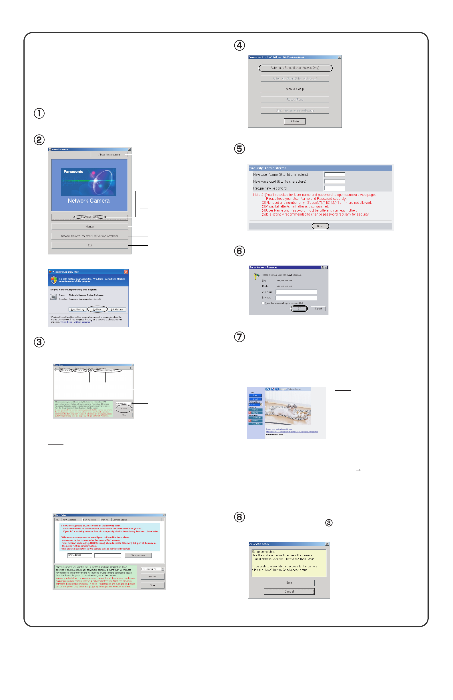
Insert the Setup CD-ROM into the CD-ROM drive of the PC.
(If the Network Camera Setup window is not displayed automatically,
double-click the "Setup.exe" file on the Setup CD-ROM.)
Click [Camera Setup].
Displays version information
about this program.
Sets up this product or the camera.
Displays the manuals.
If your PC does not have Adobe®
Acrobat® Reader®, install it from
the Adobe Reader website.
Click [Automatic Setup (Local Access Only)].
Enter the user name and password, and click [Save].
Installs Network Camera Recorder
trial version.
Closes the Setup Program.
•
If the Windows Security Alert is displayed, click [Unblock].
Select this product to set up and click [Execute].
This program searches for this product that are connected to the router
•
and displays their MAC Addresses, IP addresses and Port Numbers.
MAC
Address
IP
Address
• The MAC Address on the bottom (see page 11 of the Operating Instructions
on the Setup CD-ROM.) of this product shows which product you select on
the List window.
No.
StatusPor t
List window
Displays IPv4 or
IPv6 information.
Notes
• If the indicator does not light green, check the connection. (see page 10 of
the Operating Instructions on the Setup CD-ROM).
• If more than 20 minutes have passed since this product was turned on, this
product cannot be set up from the Setup Program. Disconnect the AC cord
from the outlet, and reconnect it again, and restart the Setup Program.
• The Setup Program may not list this product due to your firewall or antivirus
software settings on your PC. If you cannot disable your firewall or antivirus
software, you can set up this product by entering this product MAC address
on the following window. The product's MAC address can be found on the
label affixed to the bottom of each product. See page 11 of the Operating
Instructions on the Setup CD-ROM for details.
Enter the user name and password that were set, and
click [OK].
When the Single Camera page is displayed, setup is
completed.
•
If the Security Warning window is displayed when installing ActiveX
Controls, click [Yes].
•
To install ActiveX Controls on Microsoft® Windows® XP Service Pack
2, see "Security Warning window on Microsoft Windows XP Service
Pack 2" on the last page.
Notes
• Some cameras may display black
lines at the end on the image due to
the gap of the display area. Adjust
the picture position (see page 67 of
the Operating Instructions on the
Setup CD-ROM).
• To ensure that the most current
image is displayed, Internet Explorer
should be configured as follows. This
will not have a negative effect on
normal use.
1. While viewing any website, click
[Tools] [Internet Options].
2. In the section "Temporary Internet
Files", click [Settings] and check
[Every visit to the page].
®
Click [Next] to set up the Internet access to this
product and go to step in "Set up Internet access
to this product." on the next page.
• Click [Cancel] to finish setup.
4.
Set up Internet access to this product
Registration with the "Viewnetcam.com FREE DDNS service"
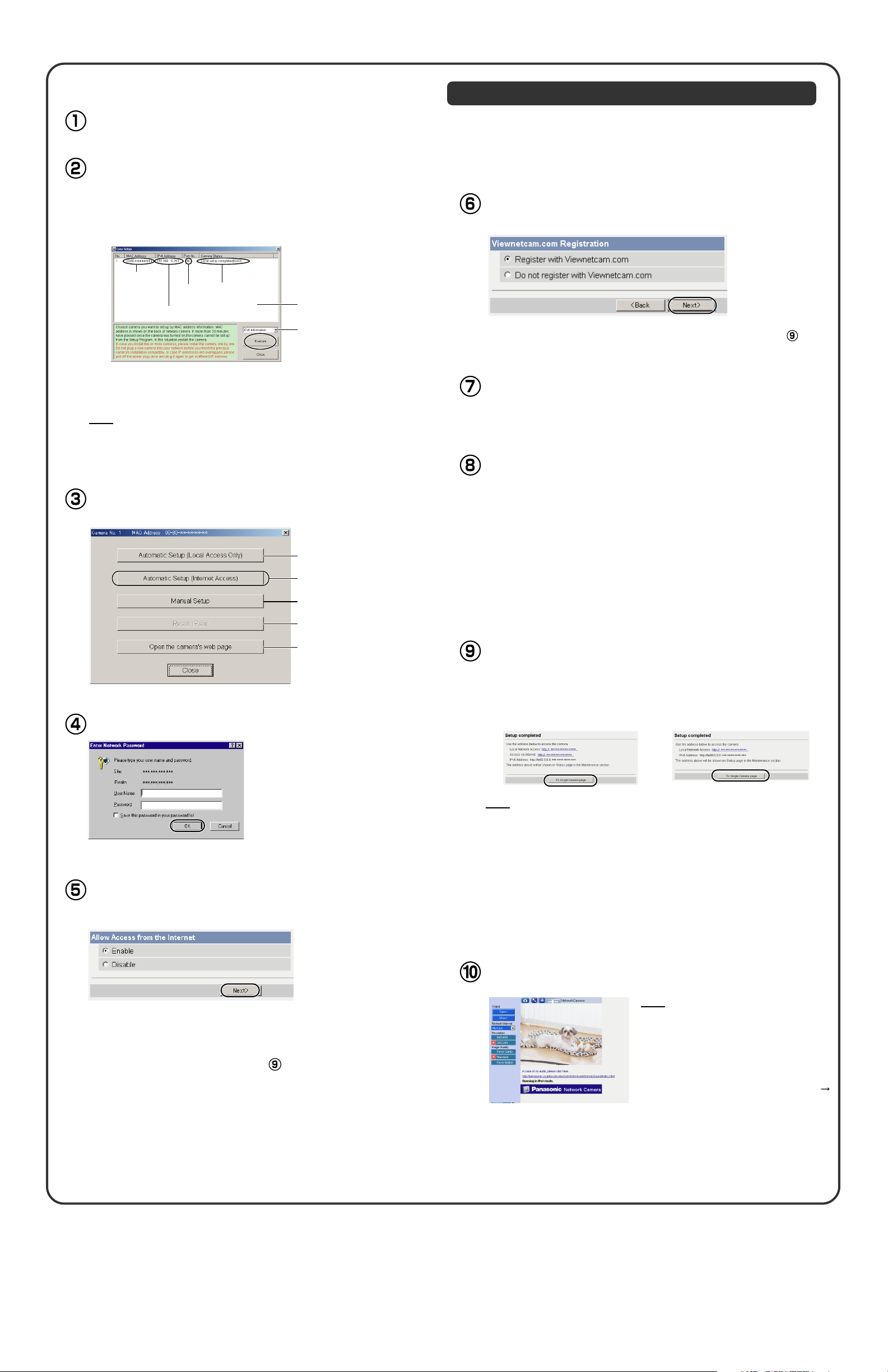
Display the list window. (See the previous page)
Select this product on the list to set up the Internet
access and click [Execute].
•
This program searches for this product or the cameras that are
connected to the router and displays their MAC Addresses, IP
addresses and Port Numbers.
MAC
Address
IP
Address
•
The MAC Address on the bottom (see page 11 of the Operating Instructions
on the Setup CD-ROM.) of this product shows which product you select on the
List window.
No.
StatusPor t
List window
Displays IPv4 or
IPv6 information.
Note
If more than 20 minutes have passed since this product was turned on, this
product cannot be set up from the Setup Program. Disconnect the AC cord from
the outlet, and reconnect it again, and restart the Setup Program.
Click [Automatic Setup (Internet Access)].
Sets up this product
to view on the LAN.
Sets up the Internet access
to this product.
Manually sets up this product.
By registering with the Viewnetcam.com FREE DDNS service, you can
create a personalized web address at which this product's live video
can always be found on the Internet. For detailed information, access
"http://www.viewnetcam.com".
To register with the "Viewnetcam.com FREE DDNS service",
check [Register with Viewnetcam.com] and click [Next>].
•
If you select [Do not register with Viewnetcam.com], skip to step .
The Enter Network Password window is displayed.
Enter the user name and password that were set,
and click [OK].
After a while, the "Viewnetcam.com FREE DDNS
service" website is displayed. Follow the displayed
instructions for registration.
•
If the message "Failed to configure the router's Port Forwarding by UPnP"
is displayed, your router may not support UPnP
Enable your router's UPnP
router's manual, and try Automatic Setup again. For more information about
setting up a router, refer to the Panasonic support web-site at
http://panasonic.co.jp/pcc/products/en/netwkcam/.
•
If the message "Failed to register with Viewnetcam.com." is displayed, confirm that the router is connected to the Internet.
TM
or set Port Forwarding manually following the
TM
or UPnPTM is not enabled.
Disables IPsec. If disabled,
the button is displayed gray.
Displays the Setup page.
(See page 34 in the Operating
Instructions on the Setup CD-ROM)
Enter the user name and password that were set, and click [OK].
When using a router supporting UPnPTM, check [Enable]. When
TM
using a router not supporting UPnP
, check [Disable]. Then
click [Next>].
When "Setup completed" is displayed, click [To
Single Camera page].
•
When [Enable] was selected
at the selection "Allow Access
from the Internet".
Note
•
The port number must be specified at the end of the camera URL.
For example
Using port 80: http://(Cameraname).viewnetcam.com
or http://IP Address
Using any other port: http://(Cameraname).viewnetcam.com:Port Number
or http://IP Address:Port Number
•
The URL for local network access may be different from the one set up on
the previous page. Make a note of the URL here again.
•
When [Disable] was selected at
the selection "Allow Access
from the Internet".
•
Check if your router supports UPnPTM referring to the router's manual.
If UPnP
for port forwarding. Refer to the router's manual for instruction on
how to do it.
•
If you select [Disable], skip to step .
TM
is not supported, the router has to be manually configured
When the Single Camera page is displayed, the
setup is completed.
Note
•
The banner is displayed only when
Internet access has been permitted.
•
To ensure that the most current image is
displayed, Internet Explorer should be
configured as follows. This will not have a
negative effect on normal use.
1. While viewing any website, click [Tools]
[Internet Options].
2. In the section "Temporary Internet Files",
click [Settings] and check [Every visit to
the page].
Setting up this product Using the MAC Address on the Setup Program
OUT
IN
OUT
IN
OUT
UDIO
VIDEO
12
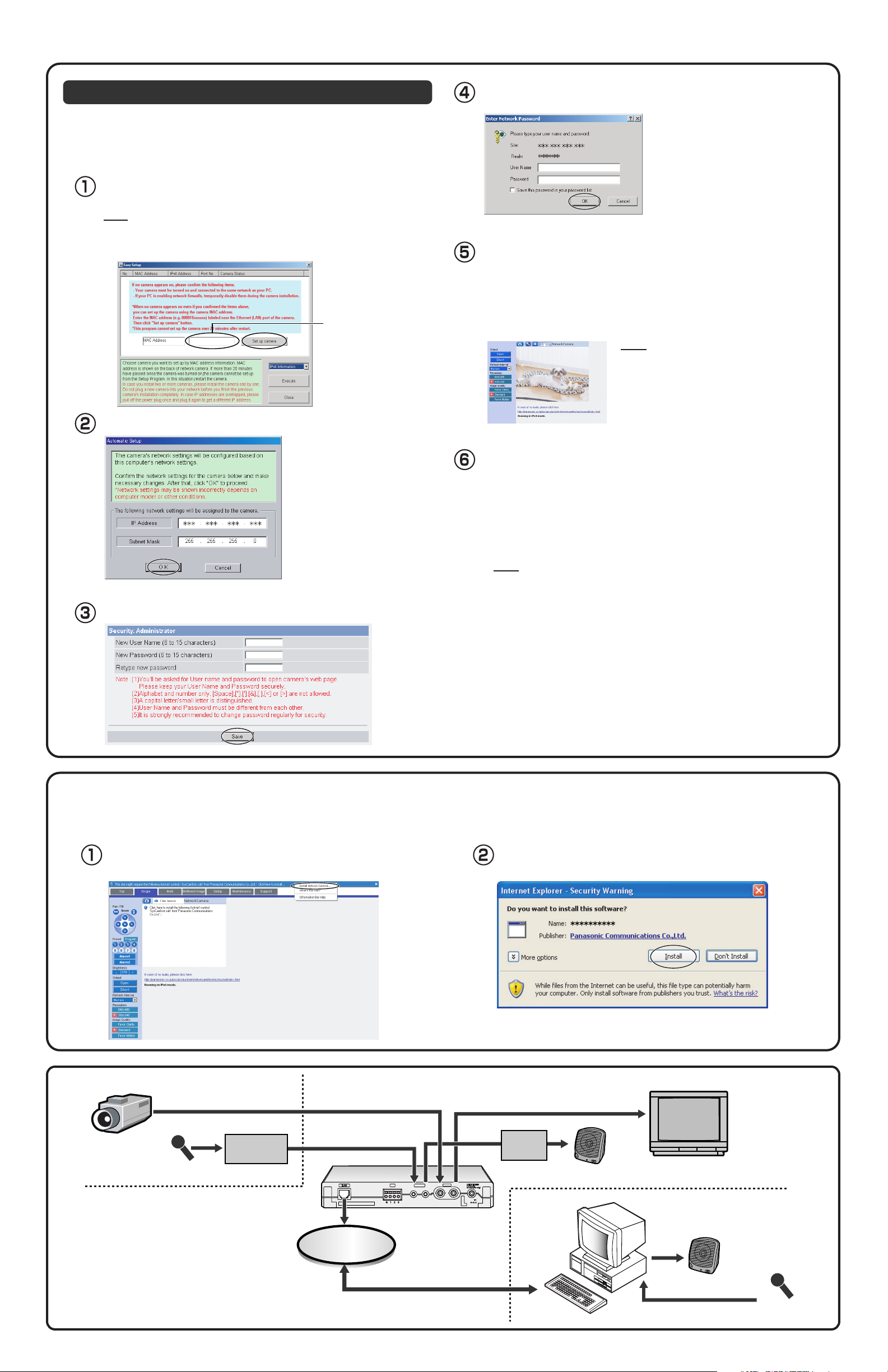
The Setup Program may not list this product due to your firewall or
antivirus software settings on your PC. If you cannot disable your
firewall or antivirus software, you can set up this product using this
product MAC address as shown below.
Enter this product's MAC address in the data field,
and click [Set up camera].
Note
This product's MAC address can be found on the sticker affixed to the bottom
of this product (see page 11 of the Operating Instructions on the Setup CDROM for details).
Enter the MAC address.
Enter the user name and password that you set, and click [OK].
When the Single Camera page is displayed, the setup
is completed.
• If the Security Warning window is displayed to install ActiveX Controls,
click [Yes].
• To install ActiveX Controls on Microsoft Windows XP Service Pack 2, see
"Security Warning window on Microsoft Windows XP Service Pack 2"
below.
Note
• See page 16 of the Operating Instructions on
the Setup CD-ROM for the Single Camera
page.
• If you enable Internet access to this product,
follow the procedures below.
After confirming the network settings, click [OK].
•
After about a minute, the Security: Administrator page is displayed.
Enter the user name and password, and click [Save].
Allow the Internet access to this product.
• When you are using a router supporting UPnP
1. Enable the Auto Port Forwarding feature on the UPnPTM page (see page
55 of the Operating Instructions on the Setup CD-ROM).
2. Register with the DynamicDNS service on the DynamicDNS page (see
page 58 of the Operating Instructions on the Setup CD-ROM).
3. Confirm the Internet access to this product (see page 12 of the Operating
Instructions on the Setup CD-ROM).
TM
Note
If you cannot access this product, see page 7, 8 and 9 in the
Troubleshooting on the Setup CD-ROM.
• When you are using a router not supporting UPnP
Follow the procedures shown on page 57 of the Operating Instructions on the
Setup CD-ROM.
TM
Security Warning window on Microsoft Windows XP Service Pack 2
To view a video (Motion JPEG) or to listen to audio feature, ActiveX Controls must be installed.
Follow the steps shown below to install ActiveX Controls.
Click the warning displayed above the tabs, and click [Install
ActiveX Control...].
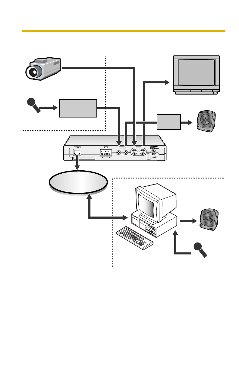
Example of connection
Click [Install].
Analog Camera
Microphone
(Local Audio)
Amplifier or
mixer
Network
Amplifier
OUT
IN
12
V
VIDEO
OUT
IN
AUDIO
I/O
OUT
IN
Speaker
Monitor
Speaker
Microphone
(Remote Audio)
Installation
Network Camera Server
Model No. BB-HCS301A
IMPORTANT SAFETY INSTRUCTIONS
When using this unit, basic safety precautions should always be
followed to reduce the risk of fire, electric shock, or personal injury.
1. Read and understand all instructions.
2. Keep these instructions.
3. Heed all warnings.
4. Follow all instructions.
5. Do not block any ventilation openings. Install in accordance with the
manufacturer's instructions.
6. Do not install near any heat sources such as radiators, heat registers,
stoves, or other devices (including amplifiers) that produce heat.
7. Protect the AC adaptor cord and AC cord from being walked on or
pinched particularly at plugs, convenience receptacles, and the point
where they exit from the unit.
8. The AC cord is used as the main disconnect device, ensure that the
socket-outlet is located/installed near the equipment and is easily
accessible.
9. Do not touch the unit or the AC adaptor cord and AC cord during
lightning storms.
10.Unplug the unit when unused for long periods of time.
11.Refer all servicing to qualified service personnel. Servicing is required
when the unit has been damaged in any way, such as when the AC
adaptor, AC cord or plug is damaged, the unit does not operate
normally, or after the unit has been dropped.
12.Unplug this unit from power outlets if it emits smoke, an abnormal
smell or makes unusual noise. These conditions can cause fire or
electric shock. Confirm that smoke has stopped and contact an
authorized service center.
13.Keep the SD memory card (customer-provided) out of reach of children
to prevent swallowing.
SAVE THESE INSTRUCTIONS
Please read this manual before using and save this manual for future
reference.
Panasonic Website: http://www.panasonic.com/netcam for customers in
the USA or Puerto Rico
How to Use This Documentation
This product includes the following 4 manual types.
• Installation (This manual)
This manual provides explanations for items included with this product.
• Getting Started
Getting Started provides explanations for the initial configuration.
The Getting Started helps you to easily configure this product.
• Operating Instructions (Included on the Setup CD-ROM)
Operating Instructions explains about operations, settings and features
when using this product.
• Troubleshooting (Included on the Setup CD-ROM)
Troubleshooting provides explanations for troubleshooting tips.
Trademarks
• Microsoft and Windows are either registered trademarks or trademarks
of Microsoft Corporation in the United States and/or other countries.
• Pentium is a trademark or registered trademark of Intel Corporation or
its subsidiaries in the United States and other countries.
• SD mark is a trademark of the SD Card Association.
• All other trademarks identified herein are the property of their respective
owners.
• This software is based in part on the work of the Independent JPEG
Group.
Abbreviations
• UPnP is the abbreviation for "Universal Plug and Play".
• "Network Camera" or "Analog Camera connected to this product" is
called "Camera" in this Installation manual.
FCC and Other Information
This equipment has been tested and found to comply with the limits for a Class B digital device, pursuant to Part 15 of the FCC Rules. These limits are
designed to provide reasonable protection against harmful interference in a residential installation. This equipment generates, uses and can radiate radio
frequency energy and, if not installed and used in accordance with the instructions, may cause harmful interference to radio communications.
However, there is no guarantee that interference will not occur in a particular installation. If this equipment does cause harmful interference to radio or
television reception, which can be determined by turning the equipment off and on, the user is encouraged to try to correct the interference by one or
more of the following measures:
• Reorient or relocate the receiving antenna.
• Increase the separation between the equipment and receiver.
• Connect the equipment into an outlet on a circuit different from that to which the receiver is connected.
• Consult the dealer or an experienced radio/TV technician for help.
This device complies with Part 15 of the FCC Rules. Operation is subject to the following two conditions:
(1) This device may not cause harmful interference, and (2) this device must accept any interference received, including interference that may cause
undesired operation.
Environment:
Do not install this product where the temperature is less than 0 °C (+32 °F) or greater than +40 °C (+104 °F). Allow 10 cm (4 inches) clearance around
the unit for proper ventilation. Avoid excessive smoke, dust, mechanical vibration, shock, or direct sunlight.
Routine care:
Wipe the unit with a soft cloth. Do not use benzine, thinner, or any abrasive powder.
When you leave the unit unused for a long period of time, disconnect the AC adaptor cord from the outlet.
If you have any problems:
Consult an authorized Panasonic Factory Service Center.
CAUTION:
Any changes or modifications not expressly approved by the party responsible for compliance could void the user's authority to operate this device.
No responsibility will be taken by our company with respect to consequences
resulting from the use, damage or both of this product.
CR Coin Cell Lithium Battery Information:
This product contains a CR Coin Cell Lithium Battery which contains Perchlorate Material - special handling may apply.
See www.dtsc.ca.gov/hazardouswaste/perchlorate.
Audio and Video Recording Notice:
PLEASE NOTE that under certain circumstances, audio/video recording may be PROHIBITED by law. This device should be used only in
compliance with all applicable federal, state and local statutes.
2005 Panasonic Communications Co., Ltd. All Rights Reserved.
PSQX3858ZB KK0605YT1056
System Requirements for your PC
Security Cautions
Your PC (Personal Computer) and network must meet the following
technical specifications for this product to work properly.
For IPv4 Connection
Item Description
Operating
System
CPU
Protocol
Interface
Web Browser
Audio
Microsoft® Windows® XP, Microsoft® Windows® 2000
Microsoft® Windows® Me, Microsoft® Windows® 98SE
• For viewing single camera
Pentium
• For viewing multiple cameras
Pentium 4 (1.8 GHz or greater is recommended.)
TCP/IP protocol (HTTP, TCP, UDP, IP, DNS, ARP, ICMP)
10/100 Mbps network card installed
Internet Explorer 6.0 or later
(Not included on the Setup CD-ROM)
Audio input/output feature (Microphone, speaker etc.)
®
III (800 MHz or greater is recommended.)
For IPv6 Connection
Item Description
Operating
System
CPU
Microsoft® Windows® XP Service Pack 1 or later
• For viewing single camera
Pentium III (800 MHz or greater is recommended.)
• For viewing multiple cameras
Pentium 4 (1.8 GHz or greater is recommended.)
When using this product, take appropriate measures to avoid the following
security breaches.
• Leaks of private information via this product
• Illegal use of this product by a third party
• Interference or suspension of the use of this product by a third party
• Using this product in such a way as to violate the rights of any third
party or otherwise use in violation of law
Take the following measures to avoid security breaches:
• To prevent illegal access, keep the update firmware
(If you do not have the latest version of firmware, this can lead to
blocked access or information leaks).
• You are responsible for the security settings, such as user name and
password, to access this product. This information should not be made
available to any third parties outside the user group.
• You are responsible for this product's user information, such as videos,
still images and internet contents etc. This information should not be
made available to any third parties outside the user group.
• When sending this product to be repaired with a company not related to
Panasonic, make back-up copies of files, if necessary, and reset this
product to factory default.
• When transferring this product to another party, make back-up copies of
files, if necessary, and reset this product to factory default.
• When disposing of this product, reset this product to factory default, or
erase information by means of electrical deletion or physical
dismantlement.
• Recorded files stored on the SD memory card can lead to private
information leaks. When sending this product to be repaired or
transferring it to another party, ensure that the SD memory card is
removed.
Protocol
Interface
Web Browser
Audio
Note
See Panasonic support website at
http://panasonic.co.jp/pcc/products/en/netwkcam/ for details about
network environment.
TCP/IP protocol
(HTTP, TCP, UDP, IP, DNS, ICMPv6, NDP)
10/100 Mbps network card installed
Internet Explorer 6.0 or later
(Not included on the Setup CD-ROM)
Audio input/output feature (Microphone, speaker etc.)
What is IPv6?
• IPv6 is short for "Internet Protocol Version 6".
• IPv6 was created to address the additional IP addresses that will be
needed as the Internet continues to expand.
• IPv6 is expected to gradually replace IPv4, with the 2 coexisting for a
number of years during a transition period.
• Though most ISPs (Internet Service Providers) do not yet support IPv6,
many local networks already use it. When your ISP supports IPv6, your
Panasonic will be ready!
• For more information you wish to visit http://www.ipv6.org/.
User Name and Password Protection
The use of a unique User Name and secret Password is an important
tool that will help limit unauthorized individuals from accessing this
product. If you choose to disable this tool, and choose not to limit
access by use of a User Name and Password, this may result in
access to this product by unauthorized individuals. (See page 74 of
the Operating Instructions on the Setup CD-ROM)
Included Items
The following items are provided with this product.
Additional pieces can be ordered by calling 1-800-332-5368.
Main Unit . . . . . . . . . . . . . . . . . . . . 1 pc.
AC Cord . . . . . . . . . . . . . . . . . . . . . 1 pc .
Order No.: PSJA1069Z
(Cord Length: About 1.8 m
[5 feet 11 inches])
AC Adaptor . . . . . . . . . . . . . . . . 1 pc .
Order No.: PQLV202Y
(Cord Length: About 3 m
[9 feet 10 inches])
Setup CD-ROM . . . . . . . . . . . . 1 p c.
Order No.: PSQX3860ZCD
The information in this document is subject to change without notice.
Panasonic Consumer Electronics Company,
Division of Panasonic Corporation of North America
One Panasonic Way, Secaucus, New Jersey 07094
Panasonic Puerto Rico, Inc.
San Gabriel Industrial Park, Ave. 65 de Infantería, Km. 9.5,
Carolina, Puerto Rico 00985
Copyright:
This material is copyrighted by Panasonic Communications Co., Ltd.,
and may be reproduced for internal use only. All other reproduction, in
whole or in part, is prohibited without the written consent of
Panasonic Communications Co., Ltd.
Installation
(This manual) . . . . . . . . . . . . . . . . 1 pc.
Getting Started . . . . . . . . . . . . . . 1 pc.
For product service
Panasonic Servicenters are listed in the servicenter directory.
•
Call 1-800-272-7033 for the location of an authorized servicenter.
•
This Network Camera Server is designed for use in the United States of
•
America. Sale or use of this product in other countries/areas may violate
local laws.
When you ship the product
Carefully pack your unit, preferably in the original carton.
•
Attach a letter, detailing the symptom, to the outside of the carton.
•
Symptom
Send the unit to an authorized servicenter, prepaid and adequately
•
insured.
Do not send your unit to the Panasonic Consumer Electronics Company
•
listed left or to executive or regional sales offices. These locations do
not repair consumer products.
D
UDIO
VIDEO
PO
WER
C
I
P
N
O
W
E
R
V
I
D
E
I
N
O
AU
I
D
N
I
O
I
N
Operating Instructions
Network Camera Server
Model No.
BB-HCS301A
Please read this manual before using and save this manual for future reference.
Panasonic Network Camera Website: http://www.panasonic.com/netcam
for customers in the USA or Puerto Rico

Operating Instructions
Main Features
Motion-JPEG Conversion from Analog Camera Image
When the analog camera is connected to this product, you can view the image from
the Internet.
Video Output Terminal and Local Audio Mode
This product provides Video Output Terminal that allows you to output the video
signal from Video Input Terminal and Local Audio Mode that allows you to output
the audio signal from Audio Input Terminal. By cascading this product, the
simultaneous accesses to the same video or audio can be increased (Up to 5).
IPv6*1 Supported
This product supports IPv6 (Internet Protocol Version 6), IPv6 was created to
address the additional IP addresses that will be needed as the Internet continues
to expand. Since this product also supports IPv4 that is currently used, it is "dual
stack" design will seamlessly operate while IPv6 is phased in. For more information
in IPv6 you wish to visit
Audio 2-way Communication*2 (Walkie-talkie Type)
This product now provides 2-way audio, between this product and your PC. You will
be able to hear the person on this product and respond using a microphone
connected to your PC's sound card (customer-provided.) They will hear your
response through the amplified speaker (customer-provided) connected this
product.
http://www.ipv6.org/. See page 14 for more information.
Note
PLEASE NOTE that under certain circumstances, audio/video recording may
be PROHIBITED by law. This device should be used only in compliance with
all applicable federal, state and local statutes.
IPsec Security
IPsec is a data encryption method to prohibit interference by a third party. This
product increases security by using IPsec and password authentication.
*1
To connect in IPv6, subscribe to the ISP's "IPv4/IPv6 Dual-Stack" or "IPv6 over IPv4
Tunneling" service. This product does not work in IPv6-only network.
*2
Audio feature does not work on cell phones. Talk button and Listen button cannot be used
simultaneously. In consequence of traffic and network environments, the audio may be
delayed or may break up.
2

Operating Instructions
Digital Zoom Feature
*1
This product has a 10× digital zoom feature.
This feature allows you to increase or decrease the size of the object on the Single
Camera screen, the Multi Camera screen, and the Buffered Image screen.
Therefore, it will be easy to view the object that located to a distant place.
*2
A mouse
wheel operation or clicking the right mouse button increases or decreases the size
of the object on the Single Camera screen.
Motion Detection Feature
This product has a motion detection feature that detects movement, such as
people, based on the preset threshold and sensitivity on the image.
This product can buffer the images, transfer them to an FTP server or send them
by E-mails using the motion detection function as a trigger.
Multi-Camera Supported
Multi-Camera page displays up to 4 cameras while supporting each audio 2-way
communication. This product can switch 3 sets of 4 cameras. Additionally, this
product can displays maximum 12 cameras on a page in a static image.
DynamicDNS Service Supported
DynamicDNS service allows you to access this product over the Internet with your
favorite domain name (e.g. bob.viewnetcam.com) instead of a global IP address.
Multi-Language Display
Top page, Single Camera and Multi-Camera page can be displayed in English,
French, German, Italian, Spanish, Russian, Simplified Chinese or Japanese. The
Setup, Maintenance and Support pages are displayed only in English or Japanese.
Alarm Log and Alarm Log Notification
This product notifies the signal detection log once a day by E-mail sent at a
specified time. This product can have 3 E-mail destinations. It is convenient when
this product has multiple detections such as comings and goings of people.
SD Memory Card*3 Recording
This product has an SD memory card slot. You can record images to the SD
memory card. If you enable alarm buffer/transfer, you can record the image at the
timing of signal detection of door sensor or light. About 60,000 images (320 × 240
resolution and standard quality) can be recorded to 1 GB SD memory card. If you
enable 1-minute interval timer buffer/transfer, you can record the images for about
41 days.
*1
This feature is not available when viewing on a cell phone.
*2
As the magnification increases, the image quality decreases.
*3
SD memory card is sold separately. This product supports 1 GB, 512 MB, 256 MB, 128 MB or
64 MB Panasonic SD memory card.
[For assistance, please call: 1-800-272-7033] 3
Operating Instructions
IN
OUT
OUT
OUT
UDIO
I/O
VIDEO
12
Example of connection
Analog Camera
Microphone
(Local Audio)
Amplifier or
mixer
Network
Monitor
Amplifier
Speaker
IN
OUT
IN
12
V
VIDEO
OUT
IN
AUDIO
I/O
OUT
Speaker
Microphone
(Remote Audio)
Note
When using the video output terminal, securely connect a cable from the video
output terminal of this product to the video input terminal of a monitor. If the
monitor cable becomes disconnected, and only the video input terminal of this
product is connected, the image will turn pale.
4
Operating Instructions
IN
OUT
IN
OUT
IN
OUT
UDIO
I/O
VIDEO
12
IN
OUT
IN
OUT
IN
OUT
UDIO
I/O
VIDEO
12
IN
OUT
IN
OUT
IN
OUT
UDIO
I/O
VIDEO
12
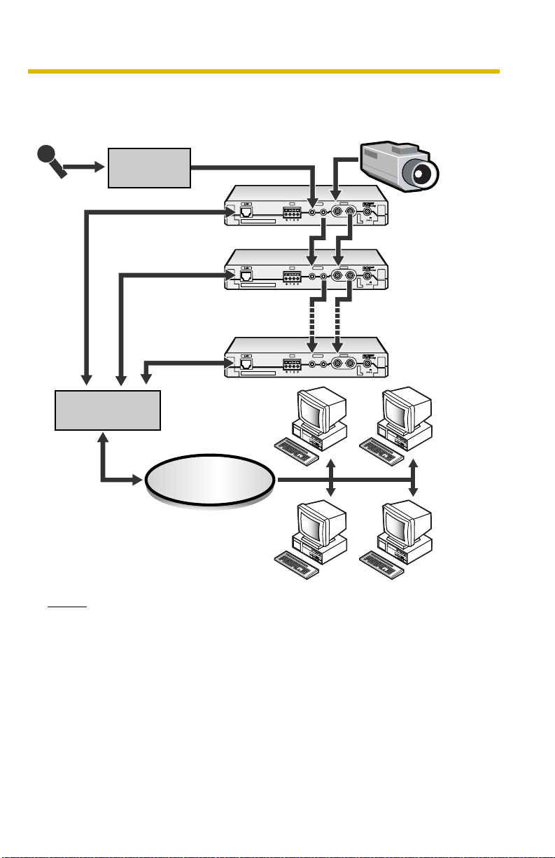
Example of cascade connection
Maximum accesses can be increased by connecting two or more products.
Analog Camera
Amplifier or
Microphone
Hub, router
mixer
VIDEO
OUT
IN
AUDIO
I/O
OUT
IN
OUT
IN
AUDIO
I/O
OUT
IN
OUT
IN
12
V
VIDEO
OUT
IN
12
V
Up to 5 products
can be connected.
VIDEO
OUT
IN
AUDIO
I/O
OUT
IN
OUT
IN
12
V
Network
Notes
• Set Local Audio for the audio output of each product in the cascade
connection (see page
69).
• The contents set on the Setup page (see page 34) is effective to only one
product. Set it to each product when using it by the cascade connection.
• The connected products have each destination URL.
• Disable the color night view mode when connecting Panasonic Network
Camera BB-HCM381A. The image is not displayed correctly.
• The refresh interval may slow and the audio may be interrupted according
to the performance and the network environment of PC.
[For assistance, please call: 1-800-272-7033] 5

Operating Instructions
Trademarks
• Adobe, Acrobat and Reader are either registered trademarks or trademarks of
Adobe Systems Incorporated in the United States and/or other countries.
• Microsoft, Windows, Hotmail and ActiveX are either registered trademarks or
trademarks of Microsoft Corporation in the United States and/or other
countries.
• Pentium is a trademark or registered trademark of Intel Corporation or its
subsidiaries in the United States and other countries.
• SD mark is a trademark of the SD Card Association.
• Screen shots reprinted with permission from Microsoft Corporation.
• All other trademarks identified herein are the property of their respective
owners.
• This software is based in part on the work of the Independent JPEG Group.
Abbreviations
• UPnP is the abbreviation for "Universal Plug and Play".
• "Network Camera" or "Analog Camera connected to this product" is called
"Camera" in this Operating Instructions.
6

Operating Instructions
Table of Contents
1 Camera Monitoring......................................................10
1.1 Product Feature Locations ........................................................... 10
1.2 Accessing this Product................................................................. 12
1.2.1 To Access this Product in IPv6 ................................................................ 14
1.3 Viewing Single Camera page ....................................................... 16
1.3.1 Zooming In and Out................................................................................. 22
1.3.2 Capturing a Still Image............................................................................ 23
1.3.3 Using Operation Bar................................................................................ 24
1.4 Listening to Audio—Talking to this product .................................. 25
1.5 Viewing Multi-Camera page ......................................................... 27
1.6 Viewing Buffered Image page ...................................................... 29
1.6.1 Deleting Buffered Images ........................................................................ 31
1.7 Viewing Still Images on Your Cell Phone ..................................... 32
2 Various Product Features...........................................34
2.1 Using Product Features ............................................................... 34
2.2 Connecting this Product to Your IPv4 Network ............................ 37
2.3 Connecting this Product to Your IPv6 Network ............................ 41
2.4 What is IPsec? ............................................................................. 45
2.5 Encrypt the Camera Image in Transport Mode ............................ 48
2.6 Encrypt the Camera Image in Tunnel Mode................................. 51
2.7 Using UPnP™ (Universal Plug and Play) .................................... 55
2.7.1
2.8 Registering with the DynamicDNS service .................................. 58
2.8.1 DynamicDNS Service (IPv4/IPv6)........................................................... 62
2.9 Setting Date and Time ................................................................. 64
2.10 Changing Camera Settings.......................................................... 67
2.11 Adjusting Audio ............................................................................ 69
2.12 Changing Authentication Setting and Administrator User Name and
2.13 Logging in to this Product ............................................................ 77
2.14 Creating, Modifying or Deleting General Users............................ 78
2.15 Procedures of Buffering or Transferring Images .......................... 81
Connecting this Product to a Router Not Supporting UPnPTM (IPv4 Only)
Password
...................................................................................... 74
.......... 57
[For assistance, please call: 1-800-272-7033] 7

Operating Instructions
2.16 Buffering or Transferring Images by Timer................................... 82
2.17 Buffering or Transferring Images by Alarm Signal........................ 91
2.18 Buffering or Transferring Images by Motion Detection Signal .... 102
2.19 Formatting the SD memory card................................................ 113
2.20 Stopping the SD Memory Recording ......................................... 114
2.21 Starting the SD Memory Recording........................................... 115
2.22 Transfer the Image in Transport Mode ....................................... 116
2.23 Transfer the Image in Tunnel Mode............................................ 117
2.24 Setting the Motion Detection...................................................... 118
2.25 Notifying Setup of an Alarm Log ................................................ 121
2.26 Changing Initial Settings on the Single Camera page or the MultiCamera page
............................................................................. 123
2.27 Configuring Multiple Images ...................................................... 126
2.28 Specifying Operation Time......................................................... 128
2.29 Controlling External Output Terminal ......................................... 130
2.30 Changing Indicator Display ........................................................ 131
3 Maintenance ..............................................................132
3.1 Maintenance page ..................................................................... 132
3.1.1 Confirming the Status............................................................................ 133
3.1.2 Confirming Session Status .................................................................... 133
3.1.3 Displaying Alarm Logs ........................................................................... 134
3.1.4 Restarting this Product .......................................................................... 134
3.1.5 Updating this Product Firmware ............................................................ 135
3.1.6 Creating Configuration File.................................................................... 138
3.1.7 Loading Settings from a Configuration File............................................ 139
3.1.8 Resetting this Product to Factory Default .............................................. 140
3.2 Support page ............................................................................. 141
3.2.1 Seeing Help page.................................................................................. 141
3.2.2 Seeing Product Information ................................................................... 141
3.2.3 Seeing Support Information................................................................... 142
3.3 External I/O ................................................................................ 143
3.4 FACTORY DEFAULT RESET Button.......................................... 145
3.5 Default Setting List..................................................................... 146
3.6 Setting an IP Address on Your PC ............................................. 154
8

Operating Instructions
3.7 Using Setup Program................................................................. 155
3.8 Setting Your PC.......................................................................... 159
3.8.1 Setting the Proxy Server Settings on Web Browser ............................. 159
3.8.2 Setting UPnP™ to Display the Shortcut in My Network Places............. 162
3.8.3 Setting the Internet Temporary File Setting on Web Browser................ 162
3.9 ASCII Character Table ............................................................... 163
3.10 File Size and Number of Buffered Images ................................. 164
3.11 Using the SD Memory Card ....................................................... 165
3.12 Number of Images on the SD Memory Card.............................. 166
3.13 Specifications ............................................................................. 167
Index..................................................................................169
[For assistance, please call: 1-800-272-7033] 9
Operating Instructions
1 Camera Monitoring
1.1 Product Feature Locations
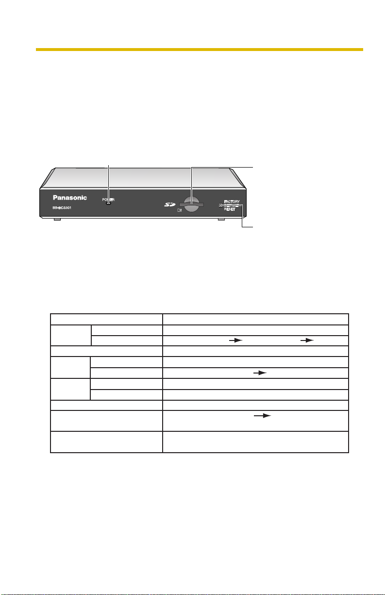
Front View
Power Indicator
The color display shows this product's status.
SD Memory Card Slot
Insert the SD Memory
card.
(see page 165)
FACTORY DEFAULT
RESET Button
Pushing the button resets
this product to factory
default.
(see page 145)
Indicator Display
Status
Powe r
on
Automatic
Setup
Using
DHCP
DEFAULT RESET button
Not on the LAN
On the LAN
Normal Operation*
Finished setting
Getting IP address*
Got IP address
Updating Firmware
Pressing FACTORY
TM
Failure Orange blinking (About a 2-second interval)
UPnP
Internal Failure Red blinking*
1
Setting
Orange blinking Green
2
*1 The indicator turns orange if this product is not connected to the LAN.
*2 The indicator blinks orange if this product is not connected to the LAN.
*3 See page 4 of the Troubleshooting on the Setup CD-ROM.
Indicator Operation
Orange blinking
Green blinking
Green
Green blinking
Green blinking
Green blinking
Green
Orange blinking
Orange blinking Turning off
(This product restarts after that.)
Green
3
10
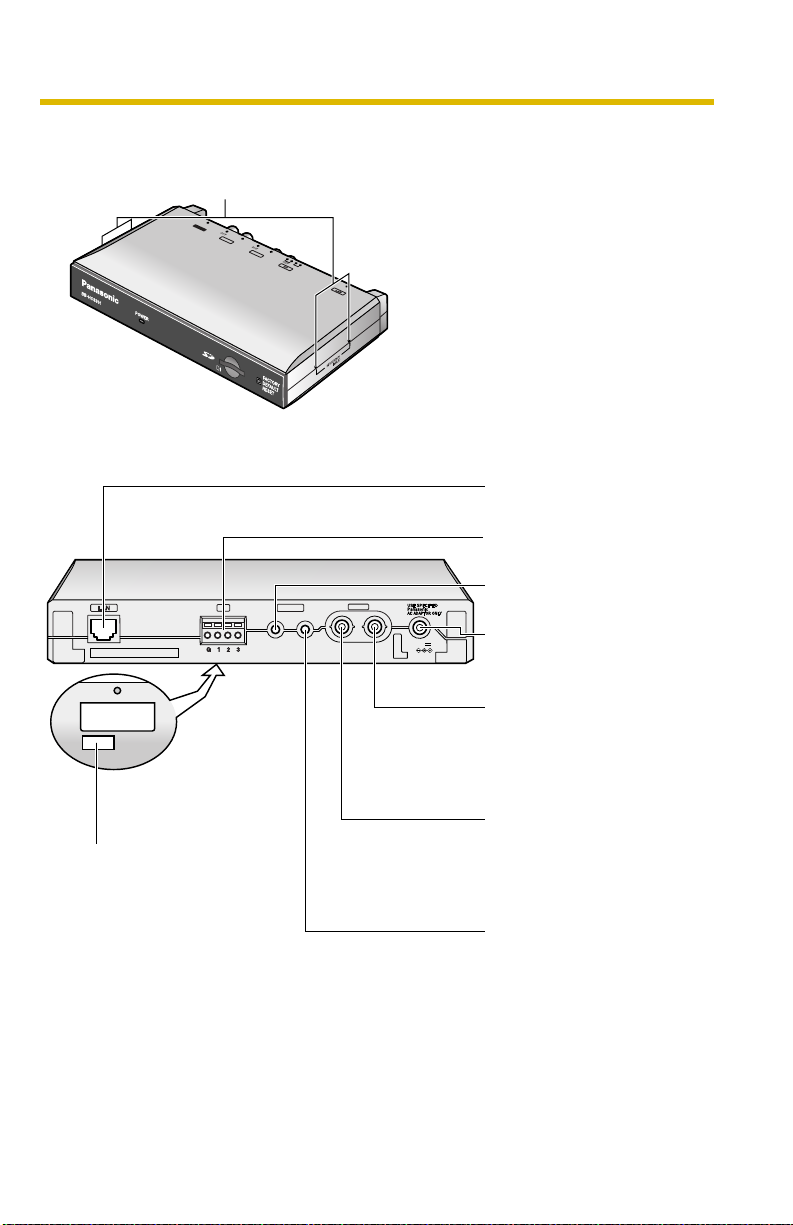
Side view
PO
WER
UDIO
VIDEO
PO
WER
OUT
OUT
12
Mounting holes
Fix a steel plate with M3 screws (customer-provided) into the 4 holes.
D
D
C
C
IN
IN
P
P
O
O
W
W
E
E
R
R
V
V
I
ID
D
E
E
IN
I
N
O
O
AU
A
U
I
I
D
D
N
N
IO
I
O
IN
IN
Rear View
Ethernet (LAN) port
(See Getting Started)
External I/O
(see page 143)
I/O
OUT
IN
The MAC address is
written on the bottom label.
VIDEO
OUT
IN
AUDIO
OUT
IN
12
V
Audio Input Terminal
(see page 26)
DC IN jack
Use the attached specified
AC adaptor.
Video Output Terminal
(BNC Terminal)*
Connect it to the video
input terminal of the
monitor.
Video Input Terminal
(BNC Terminal)*
Connect it to the video
output terminal of the
camera.
Audio Output Terminal
(see page 26)
Operating Instructions
* Terminating resistance (75Ω) is built into this product's video input terminal. This
terminating resistance is opened automatically when the cable is connected to
both video input terminal and the video output terminal. In this case, it is
terminated by terminating resistance that has built to the monitor's input terminal
connected with the video output terminal with the cable.
[For assistance, please call: 1-800-272-7033] 11
Operating Instructions
1.2 Accessing this Product
1. Start up the web browser on your PC.
2. Enter "http://IPv4 Address (or URL):Port Number" on the address bar, and
press [Enter] on the keyboard.
• When port number is 80 (default), you do not need to enter port number.
See page
• For IPv6 connection, see page 14 and page 15, and prepare the
requirements. Enter the "http://(IPv6-registered URL):Port Number" on
the address bar.
• If the image is not displayed, see page 7 to page 12 of the Troubleshooting
on the Setup CD-ROM.
E.g. http://192.168.0.253:50000 (in IPv4)
http:// .viewnetcam.com:50000 (in IPv6)
3. The Enter Network Password window is displayed, and enter the user name
and password that were set, and click [OK].
Note
When [Permit access from guest users] is set on the Security: Administrator
page (see page
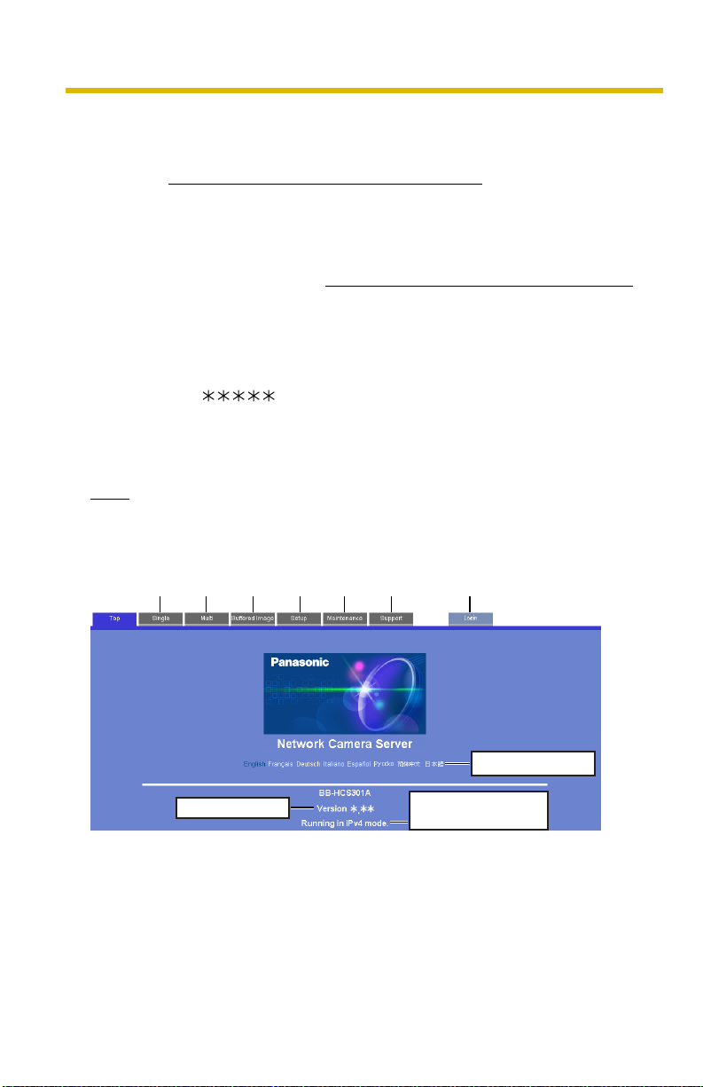
4. Click the following tabs to display each page.
A B C D E F G
39 for details about port number.
74), authentication window will not be displayed.
12
Select a language.
Version Number
A To Single Camera page (page 16) B To Multi-Camera page (page 27)
C To Buffered Image page (page 29) D To Setup page (page 34)
E To Maintenance page (page 132) F To Support page (page 141)
G To log in to this product (page 77)
Displays IPv4, IPv6
or IPsec connection.

Operating Instructions
Notes
• When users other than an administrator are accessing this product,
[Setup] and [Maintenance] tab will not be displayed. Additionally, when
[Do not permit access from guest users] is set on the Security:
Administrator page (see page
• If [View Multi-Camera page] or [View Buffered Image page] is not
permitted on the General User page (see page
[Buffered Image] tab will not be displayed.
74), [Login] tab will not be displayed.
78), [Multi-Camera] or
[For assistance, please call: 1-800-272-7033] 13

Operating Instructions
1.2.1 To Access this Product in IPv6
You need to prepare the followings to access this product in IPv6.
• PC Requirements
Operating System: Windows XP Service Pack 1 or later
Web Browser: Internet Explorer 6.0 or later
• An IPv6 Router
• An IPv6 Connection Service
To connect in IPv6, subscribe to the ISP's "IPv4/IPv6 Dual-Stack" or "IPv6 over
IPv4 Tunneling" service. This product does not work in IPv6-only network.
IPv6 Domain Name Service
In Windows XP, you cannot access this product entering IP address on the web
browser. You need to enter IPv6 URL registered in the domain name service. We
recommend Viewnetcam.com service (see page
Ask your ISP about other IPv6 domain name service.
What is IPv6?
• IPv6 is short for "Internet Protocol Version 6".
• IPv6 was created to address the additional IP addresses that will be
needed as the Internet continues to expand.
• IPv6 is expected to gradually replace IPv4, with the 2 coexisting for a
number of years during a transition period.
• Though most ISPs (Internet Service Providers) do not yet support IPv6,
many local networks already use it. When your ISP supports IPv6, this
product will be ready!
• For more information you wish to visit http://www.ipv6.org/.
58) as a domain name service.
14

Operating Instructions
Setting up the IPv6 Router, your PC, and this Product
Setting up the IPv6 Router
Set up the router as you subscribe to the IPv6 service. If the access from WAN side
is disabled on the router, enable the TCP packets from WAN side in the packet
filtering.
Setting up your PC
1. Click [Start] [All Programs] [Accessories] [Command Prompt].
• Command Prompt window is displayed.
2. Enter "ipv6 install".
• "Succeeded" is displayed.
Notes
• If Windows XP Service Pack 1 or later is not installed, "Succeeded" will
not be displayed. Install it on your PC.
• When you use Windows XP Service Pack 2, click [Start] [Control
Panel] [Security Center] [Windows Firewall] [Advanced]
tab [Settings] button of ICMP in the Windows Firewall window, then
check [Allow incoming router request] check box in the ICMP Settings
window.
3. Enter "ipconfig".
• If the IPv6 address is properly assigned to your PC, IPv6 address will be
displayed on the window.
Setting up this Product
Usually, IPv6 address is automatically assigned. If you assign a static IPv6
address, see page
domain name service such as Viewnetcam.com, and register the URL.
41. To access this product in IPv6, you need to subscribe to the
Confirming that You Can Access this Product
Confirm that the image is properly displayed (see page 12).
[For assistance, please call: 1-800-272-7033] 15
Operating Instructions
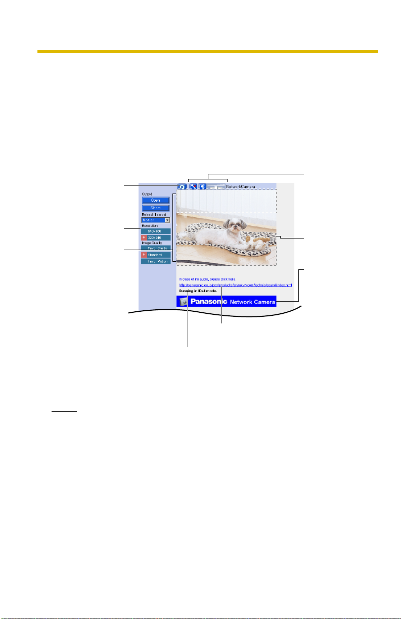
1.3 Viewing Single Camera page
1. Access this product (see page 12).
• The Top page is displayed.
2. Click the [Single] tab at the top of the page.
• When Security Warning window is displayed, click [Yes] (see page 18).
• See page 19 for Security Warning window when using Microsoft®
Windows® XP Service Pack 2.
Capture Image
Button
(See page
Operation Bar
(See page 24)
Digital Zoom
(See page 22)
23)
Click the URL in case
of no audio.
Displaying to operate
with IPv4, IPv6, or IPsec.
Audio Control
Bar (Talk Button,
Listen Button
and Adjustment
Bar)
(See page 25)
Camera Image
The banner is
displayed.
(See page 21)
16
3. Close the web browser.
Notes
• When the camera image is not displayed correctly, click [Refresh] at the
tool bar on the web browser. The image will be refreshed.
• Refresh interval is [Motion] by default. You can change it on the operation
bar (see page
• Refresh interval may change depending on the network condition, PC
performance and what object you view. Using IPsec, enabling Motion
Detection or SD memory card recording will also slow refresh interval.
• When [Motion] is selected for Refresh Interval, this product allows up to 30
simultaneous accesses. When trying more than 30 accesses, the 31st
user will see a gray screen. (Maximum 30 accesses for a Buffered Image
page too.)
24).
Operating Instructions
• To reduce the data traffic, the video can be automatically changed to
refreshing still images on the General User page (see page 78).
• To display the Single Camera page directly, add it to the [Favorites] on the
web browser.
• When the IP address was changed for this product, enter it on the address
bar.
• Video may not be displayed quickly or audio may not be listened
immediately. Wait for a while.
• If you use a proxy server, set the web browser not to access the proxy
server (see page 159).
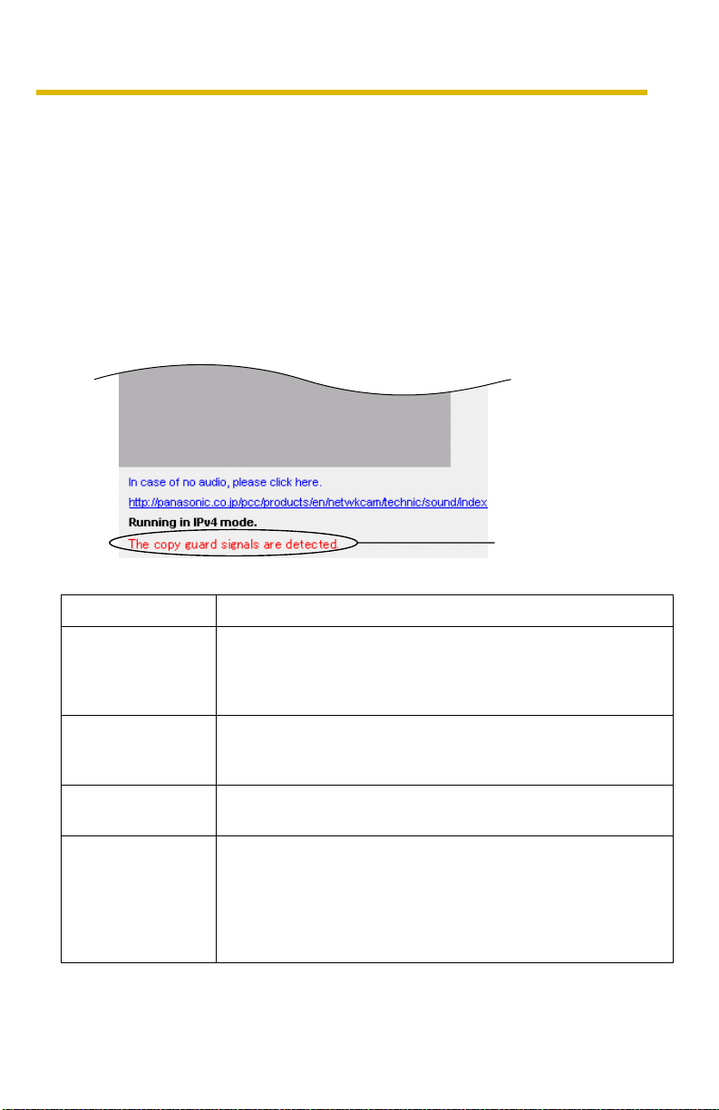
• When the image cannot be displayed, a gray screen appears. Clicking
[Refresh] on the web browser displays an error message.
An error message
is displayed.
Error Message Cause and Remedy
Copy guard signals
are detected.
A copyguard signal was detected. This image cannot be
displayed. Wait for a moment, and press the Refresh button on
your browser. If the situation does not improve, consult your
administrator.
There is no signals. Wait for a moment, and press the Refresh button on your
browser. If the situation does not improve, consult your
administrator.
It is outside the
operation time.
Accesses are
exceeding limit.
Images cannot be displayed outside the Operation Time.
Consult your administrator about Operation Time.
When [Motion] is selected for Refresh Interval, this product
allows up to 30 simultaneous accesses. When trying more than
30 accesses, the 31st user will see a gray screen. (Maximum
30 accesses for a Buffered Image page too.) Wait for a
moment, and press the Refresh button on your browser, or
switch to still images.
[For assistance, please call: 1-800-272-7033] 17
Operating Instructions
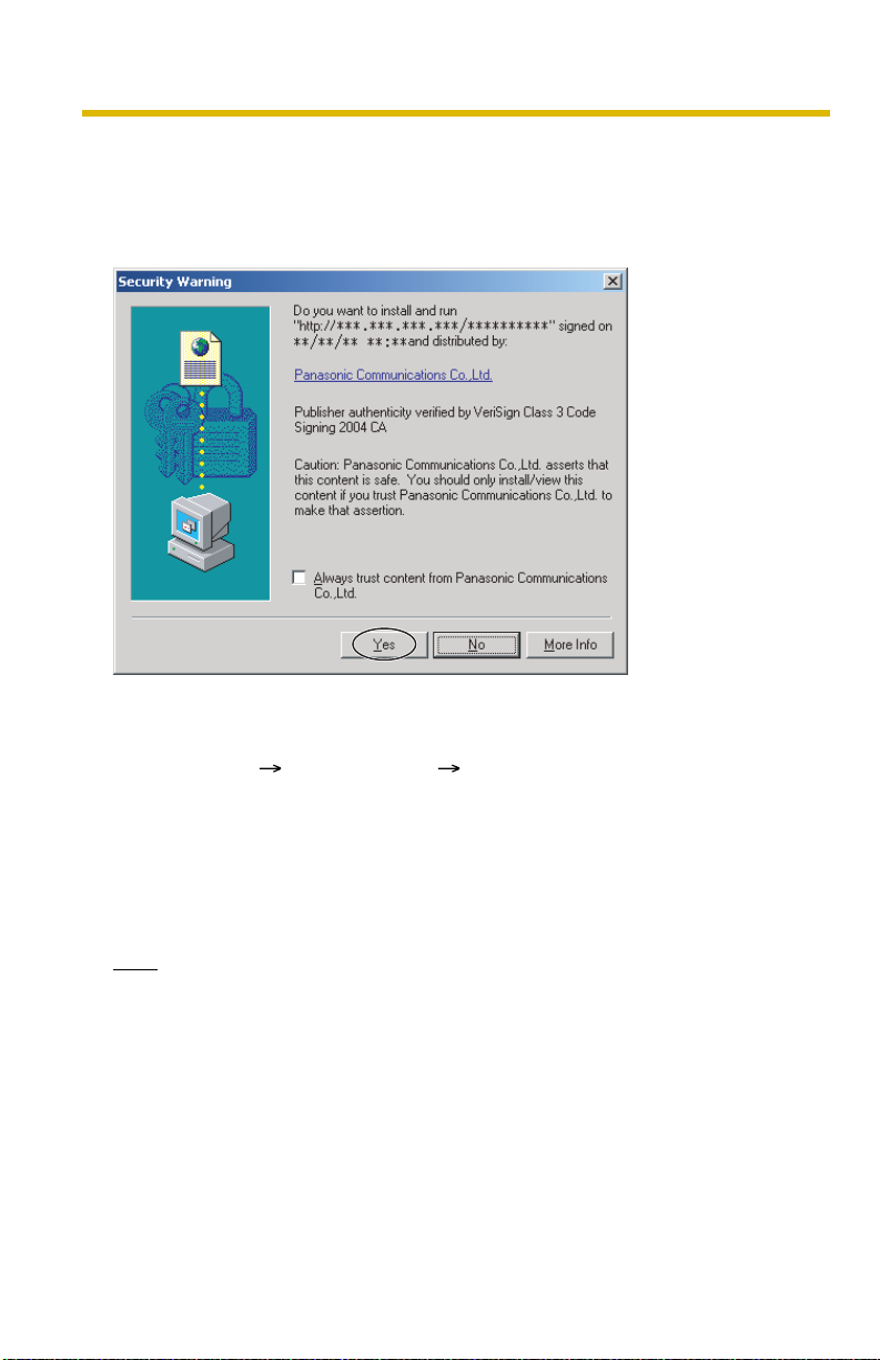
Security Warning window
To view a video (Motion JPEG) or to use audio feature, ActiveX® Controls must be
installed. When trying to display a video for the first time, Security Warning window
will be displayed. When using Windows XP or Windows 2000, log in as an
administrator to install it.
If you cannot install ActiveX Controls or you cannot see the video in the
Internet Explorer
• Click [Tools] [Internet Options] [Security] tab and click [Custom level] on
the web browser.
(1) Check "Prompt" in "Download signed ActiveX Controls".
(2) Check "Enable" in "Run ActiveX Controls and plug-ins".
• ActiveX Controls can be installed from the file on the Setup CD-ROM.
(1) Restart the PC.
(2) Confirm that Internet Explorer is closed.
(3) Double-click "ocx\ActiveXInst.exe" on the Setup CD-ROM.
Note
In some corporate network environments a firewall may be used for security
purposes. It is possible that this may prevent motion video from being displayed. In
this situation we suggest:
• Contact your network administrator.
• Try using regularly refreshed images.
18
Operating Instructions
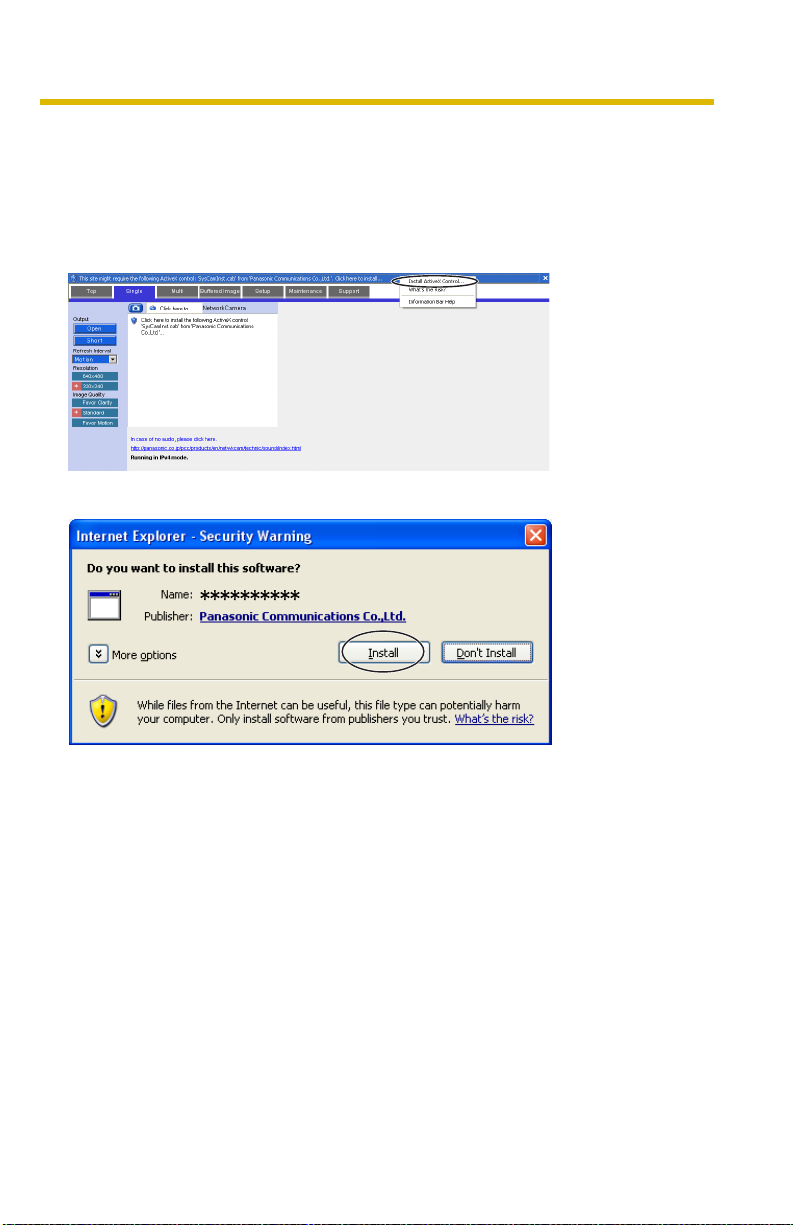
Security Warning window on Microsoft Windows XP Service Pack 2
To view a video (Motion JPEG) or to use audio feature, ActiveX Controls must be
installed.
Follow the steps shown below to install ActiveX Controls.
1. Click the warning displayed above the tabs, and click [Install ActiveX
Control...].
2. Click [Install].
[For assistance, please call: 1-800-272-7033] 19
Operating Instructions
The Image Output from the Video Output Terminal and the Image
Displayed on the Web Browser
• The video output terminal outputs the image from the video input terminal as
it is. The following features are effective only for the image on your web
browser, and not effective for the image from the video output terminal.
• Digital Zoom (See page 22)
• Click to Center with Digital Zoom (See page 22)
• Snapshot (See page 23)
• Refresh Interval (See page 24)
• Resolution (See page 24)
• Image Quality (See page 24)
• Picture Position Adjustment (See page 67)
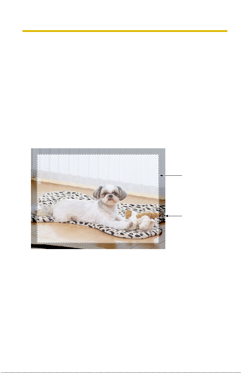
• When you view the image on the general monitor, the edge of the image is not
displayed (Overscan). On the web browser, you can view the whole area that
the monitor cannot display.
The area
displayed on the
monitor
20
The image
displayed on the
web browser

Operating Instructions
The Banner
When this product accesses the Internet, the banner displays product information
about products or announcements about the latest firmware, etc. from Panasonic.
Whether or not to display the banner can be set at Banner Display (see page
Notes
• The banner is displayed when [Yes] is checked for Allow Access from the
Internet on the Automatic Setup page, or when [Enable] is checked for Auto
Port Forwarding on the UPnP page for the Connection Mode of Static or
DHCP.
• Even if [Yes] is checked for Allow Access from the Internet on the Automatic
Setup page, or [Enable] is checked for Auto Port Forwarding on the UPnP page
for the Connection Mode of Static or DHCP, when this product is not connected
to the Internet,
is displayed.
123).
[For assistance, please call: 1-800-272-7033] 21
Operating Instructions
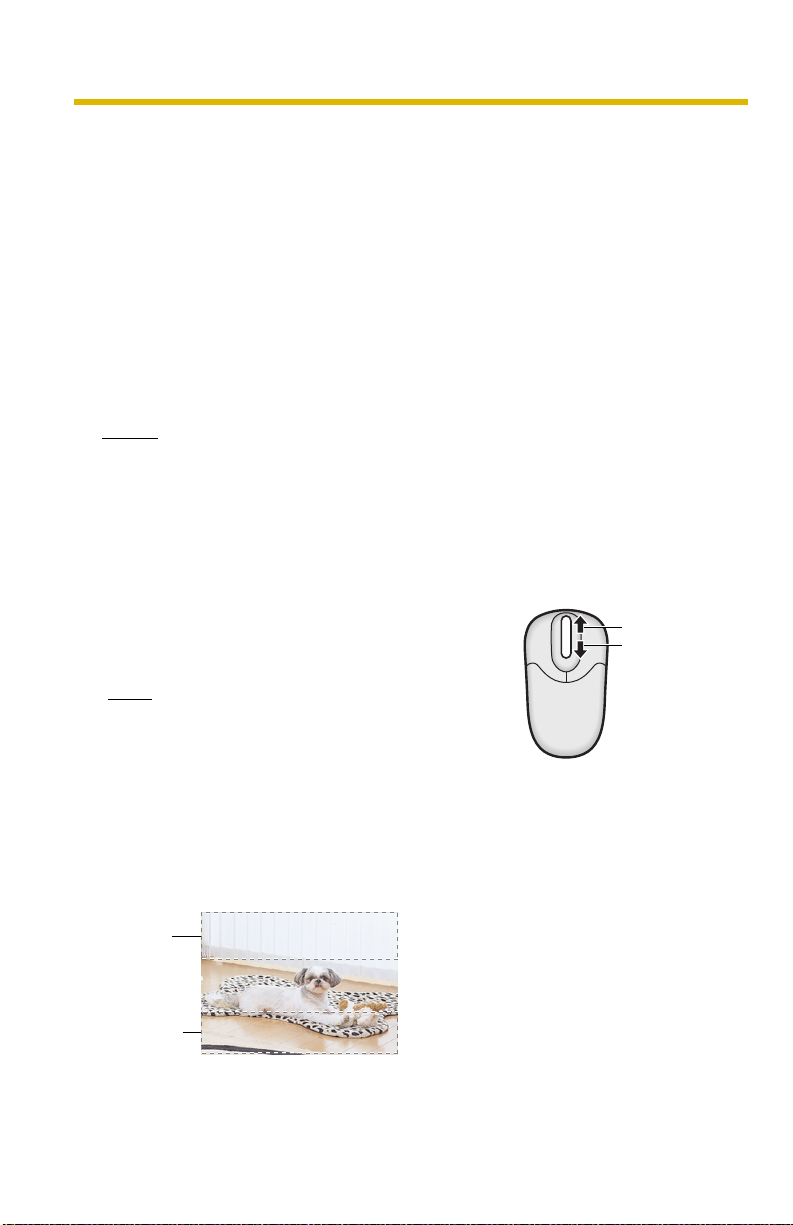
1.3.1 Zooming In and Out
This product has a 10× digital zoom feature.
There are 2 methods of increasing/decreasing the size of the object on the Single
Camera screen, the Multi Camera screen, and the Buffered Image screen (only
while playing video):
1. Rotating the mouse wheel
Rotating the mouse wheel away from you zooms in, and rotating it towards
you zooms out.
2. Clicking the right mouse button
Clicking the right mouse button on the upper third of the Single Camera
screen zooms in, and clicking on the lower third of the Single Camera
screen zooms out.
Notes
• While the image is zoomed in, the clicked point is centered (Click to Center
feature).
• This feature is not available when viewing on a cell phone.
• As the magnification increases, the image quality decreases.
Rotating the Mouse Wheel
On a screen, rotating the mouse wheel away from
you zooms in, and rotating it towards you zooms
out.
Note
The performance of the mouse varies
according to your OS.
Clicking the Right Mouse Button
Clicking the right mouse button on the upper third zooms in, and clicking on the
lower third zooms out. Zooming in and out is also available by moving the mouse
up with pressing the right mouse button, or moving the mouse down with pressing
the right mouse button.
Zoom in
Zoom out
22
Zoom in
Zoom out
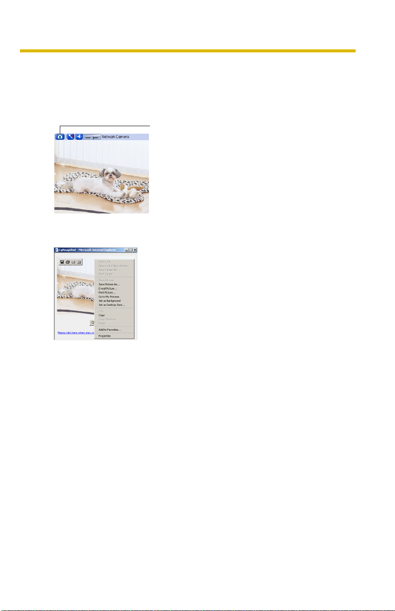
1.3.2 Capturing a Still Image
A still image can be saved on your PC.
1. Select a resolution to display an image.
2. Click the capture image button.
Capture Image Button
• The camera image opens in another window.
3. Right-click the image, and select [Save Picture As...].
Operating Instructions
• Save as dialog box is displayed.
4. Specify a folder, and click [Save].
• The camera image is saved in the folder.
5. Click [Close].
[For assistance, please call: 1-800-272-7033] 23

Operating Instructions
1.3.3 Using Operation Bar
Output
Control:
Refresh
Interval:
Resolution: Selects [640 × 480] or [320 × 240] (default) pixels.
Image
Quality:
Controls output signals of the External I/O.
Sets a refresh interval. (Motion—60-second
interval)
Selects the image quality.
• [Favor Clarity] optimizes the image for good
clarity.
• [Standard] keeps the standard quality. (default)
• [Favor Motion] optimizes the image for motion
display.
Note
When the image is not displayed soon or the image is not displayed correctly,
click "Refresh" button on your browser. The image is updated.
24
 Loading...