

Panasonic BB-HCM581CE, BB-HCM580, BB-HCM581 Installation Manual
1
Installation Guide
Network Camera
This manual is written for both the BB-HCM580 (AC Adaptor Type) and the BB-HCM581 (PoE Ready). Available features and operations vary slightly
depending on the model. You can confirm the model no. of your camera by checking the model no. printed on the front of the camera.
Please read the included Important Information before proceeding.
Complete Operating Instructions and all other documentation can be found on the included CD-ROM.
Model No.
BB-HCM580
(AC Adaptor Type)
BB-HCM581
(PoE Ready)
Indoor Use Only
Installation Procedure Overview
The following is an overview of the steps required to install and setup the camera. All steps are explained in this document unless otherwise noted.
Preparation
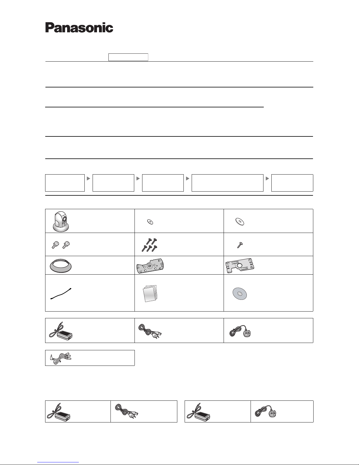
1. Confirm the following items are included in the camera’s packaging.
BB-HCM580 Only
BB-HCM581 Only
2. You will need the following additional items to install and configure the camera.
Option for BB-HCM581
You can also connect the camera using the optional Panasonic BB-HCA3CE or BB-HCA3E AC adaptor. The optional AC adaptor includes the following items.
Preparation
Confirm that you have all the
items required for
installation.
Camera Diagram
Make sure you know the
names of the camera’s
physical features.
Connections
Connecting the camera to
your network and to the power
outlet.
Setup
Setting up the camera (described in the included
Setup Guide). This involves configuring the camera
so that it can be accessed from a PC.
Mounting
Mounting or placing the
camera.
Main Unit (1 pc.) Washer S (1 pc.)
Order No. XWG26D12VW
Used when securing the safety
wire to the camera.
Washer L (1 pc.)
Order No. XWG4F16VW
Used when securing the safety
wire to the ceiling.
Screw A (2 pcs.)
Order No. XYN3+J6FJ
Used to secure ceiling plate A to
ceiling plate B.
Screw B (5 pcs.)
Order No. XTB4+20AFJ
Used to secure ceiling plate B
(4 pcs.) and the safety wire (1 pc.)
to the ceiling.
Screw C (1 pc.)
Order No. PQHV2610PJ65
Used for connecting the safety
wire to the camera.
Ceiling Mounting Cover (1 pc.)
Order No. PSKL1023Y2
Used when mounting the camera
on a ceiling.
Ceiling Plate A (1 pc.)
Order No. PQZMHCM581A
Used to secure the camera to
ceiling plate B.
Ceiling Plate B (1 pc.)
Order No. PQMD10110Z
Used to secure the camera to the
ceiling.
Safety Wire (1 pc.)
Order No. PQME10080Z
Used to secure the camera when
mounting it.
Important Information (1 pc.)
Installation Guide
(this document) (1 pc.)
Setup Guide (1 pc.)
Setup CD-ROM (1 pc.)
Order No. PNQC1048Z
Contains the Setup Program n eeded to
configure the camera, as well as the
camera’s documentation.*
*See the included Important
Information for a description of
each document.
AC Adaptor (1 pc.)
Order No. PQLV202T
Cord Length: About 3 m
AC Cord A (1 pc.)
Order No. PFJA02A006Z
Cord Length: About 1.8 m
For use in countries/areas
other than the United Kingdom
AC Cord B (1 pc.)
Order No. PSJA1106Z
Cord Length: About 1.8 m
For use in the United Kingdom
Audio/Video Cord (1 pc.)
Order No. PSJA1103Y
– a PC (see the system requirements in the Important Information document) – a LAN cable (CAT-5 straight cable)
–a router
BB-HCA3CE: For use in countries/areas other than the United Kingdom BB-HCA3E: For use in the United Kingdom
AC Adaptor (1 pc.)
Cord Length:
About 3 m
AC Cord (1 pc.)
Cord Length:
About 1.8 m
AC Adaptor (1 pc.)
Cord Length:
About 3 m
AC Cord (1 pc.)
Cord Length:
About 1.8 m
© Panasonic System Networks Co., Ltd. 2007
PQQX16052XA KK0407CM3020 (CE)
Please read this document before using the product, and save this document for
future reference.
Panasonic Network Camera Website: http://panasonic.net/pcc/ipcam/
• This document can be found on the included CD-ROM. English, French, German, Italian,
Spanish, Russian, Simplified Chinese, Korean, Danish and Swedish versions are included.
• This document (Installation Guide) explains how to physically connect the
camera to the power supply and network, as well how to mount or place the
camera for regular use.
•The Setup Guide describes how to set up the camera so that it can be
accessed using a PC.
• Refer to the Operating Instructions on the CD-ROM for details regarding
the camera’s features.
• Refer to the Troubleshooting Guide on the CD-ROM if you have any
problems configuring or using the camera.
Abbreviations
• UPnP is the abbreviation for “Universal Plug and Play”.
• The Network Camera is referred to as “the camera” in this document.
• The Setup CD-ROM is referred to as “the CD-ROM” in this document.
2
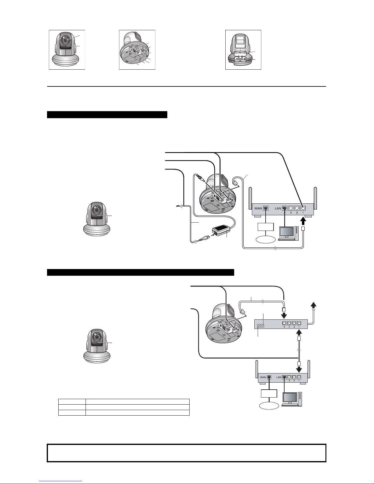
Camera Diagram
Connections
Before proceeding, confirm that your PC is connected to your router and can access the Internet. Also confirm that your router’s UPnP™ feature is enabled. (Most
routers have UPnP
™
turned off by default.) Refer to the operating instructions included with your router or to the Panasonic Network Camera website
(http://panasonic.net/pcc/ipcam/) for more information.
Follow these instructions when connecting a BB-HCM580, or when connecting a BB-HCM581 using the optional AC adaptor. Connect the camera to your router
and the power outlet as described below.
Connect the camera to your PoE hub using a LAN cable (Cat-5 straight cable) as described below.
Front View Bottom View Rear View
ABLens
Indicator
*1
C
D
E
F
G
H
I
FACTORY DEFAULT RESET
button
LAN port
DC IN jack
External I/O interface
BB-HCM580: Video terminal
BB-HCM581: Audio/Video
terminal
Ceiling plate A hole
Serial number and MAC address
label
JKSD memory card cover
FUNCTION button/indicator
*1 See 1.1 Understanding the Camera Indicator in the Troubleshooting Guide on the CD-ROM for indicator meaning.
When connecting the camera using the AC adaptor
• BB-HCM580 only: Use only the included Panasonic AC adaptor and AC cord.
• BB-HCM581 only: If using an AC adaptor, use the appropriate optional Panasonic AC adaptor; model no. BB-HCA3CE (for use in countries/areas other than
the United Kingdom), or model no. BB-HCA3E (for use in the United Kingdom).
1 Connect the LAN cable to the camera and the router.
2 Connect the AC adaptor cord to the DC IN jack.
3 Connect the AC cord to the AC adaptor, then plug the AC
cord into the power outlet.
• The lens will pan and tilt when the camera is turned on.
• Confirm that the indicator lights green after about 1
minute. If the indicator does not light green, see 1.2
Camera Indicator Issues in the Troubleshooting Guide
on the CD-ROM.
• When you operate the camera, the power outlet should
be near the camera and easily accessible.
• When the lens pans or tilts, a sound can be heard from
the camera. This is normal.
When connecting the camera using PoE (Power over Ethernet) (BB-HCM581 Only)
1 Connect a LAN cable to the camera and to the PoE hub.
• Your PoE hub must be connected to the router. Refer to the operating
instructions included with the PoE hub for connection instructions.
• The lens will pan and tilt when the camera is turned on.
2 Connect a LAN cable to a LAN port of the PoE hub and to a LAN port of the
router.
• Confirm that the indicator lights green after about 1 minute. If the
indicator does not light green, see 1.2 Camera Indicator Issues in the
Troubleshooting Guide on the CD-ROM.
• When the lens pans or tilts, a sound can be heard from the camera. This
is normal.
• Use a 4-pair UTP/STP cable.
• Do not use a relay connector or a hub between the camera and the PoE
hub. These devices may disturb the data or electricity transmission.
• If the PoE hub has indicators, the indicator lights as shown in the table
below.
Indicator Description
LINK
Turns on when the data is transmitted from the camera.
PoE
Turns on when the electricity is supplied to the camera.
• If the PoE hub is turned off or power supply is temporarily cut off by the
disconnection of the LAN cable, it may take time for the PoE hub’s
indicators to light.
• The indicator display differs depending on manufacturers, refer to the
manuals of the PoE hub.
After the camera’s indicator turns green, you may set up the camera. Continue by following the procedure described in the
included Setup Guide.
• If the indicator does not turn green, see 1.2 Camera Indicator Issues in the Troubleshooting Guide on the included CD-ROM.
A
B
C
D
E
F
G
H
I
J
K
To the
power
outlet
LAN cable
(Cat-5 straight cable)
Router
PC
AC adaptor
AC cord
Modem
Internet
Green
PoE hub
PoE indicator
LINK indicator
To the power
supply
PC
Modem
Internet
LAN cable
(Cat-5 straight cable)
Router
Green
 Loading...