

Page 1
Installation Guide
Network Camera
Indoor Use Only
Please read this document before using the product, and save this document for future
reference. Panasonic Network Camera Website: http://www.panasonic.com/netcam
for customers in the USA and Puerto Rico
Model No.
BB-HCM580A
BB-HCM581A
This manual is written for both the BB-HCM580A (AC Adaptor Type) and the BB-HCM581A (PoE Ready). Available features and operations vary slightly
depending on the model. You can confirm the model no. of your camera by checking the model no. printed on the front of the camera.
(AC Adaptor Type)
(PoE Ready)
Please read the included Important Information before proceeding.
Complete Operating Instructions and all other documentation can be found on the included CD-ROM.
• This document (Installation Guide) explains how to physically connect the
camera to the power supply and network, as well how to mount or place the
camera for regular use.
•The Setup Guide describes how to set up the camera so that it can be
accessed using a PC.
• Refer to the Operating Instructions on the CD-ROM for details regarding
the camera’s features.
• Refer to the Troubleshooting Guide on the CD-ROM if you have any
problems configuring or using the camera.
Abbreviations
• UPnP is the abbreviation for “Universal Plug and Play”.
• The Network Camera is referred to as “the camera” in this document.
• The Setup CD-ROM is referred to as “the CD-ROM” in this document.
Installation Procedure Overview
The following is an overview of the steps required to install and setup the camera. All steps are explained in this document unless otherwise noted.
Preparation
Confirm that you have all the
items required for
installation.
Camera Diagram
Make sure you know the
names of the camera’s
physical features.
Connections
Connecting the camera to
your network and to the power
outlet.
Setup
Setting up the camera (described in the included
Setup Guide). This involves configuring the camera
so that it can be accessed from a PC.
Mounting
Mounting or placing the
camera.
Preparation
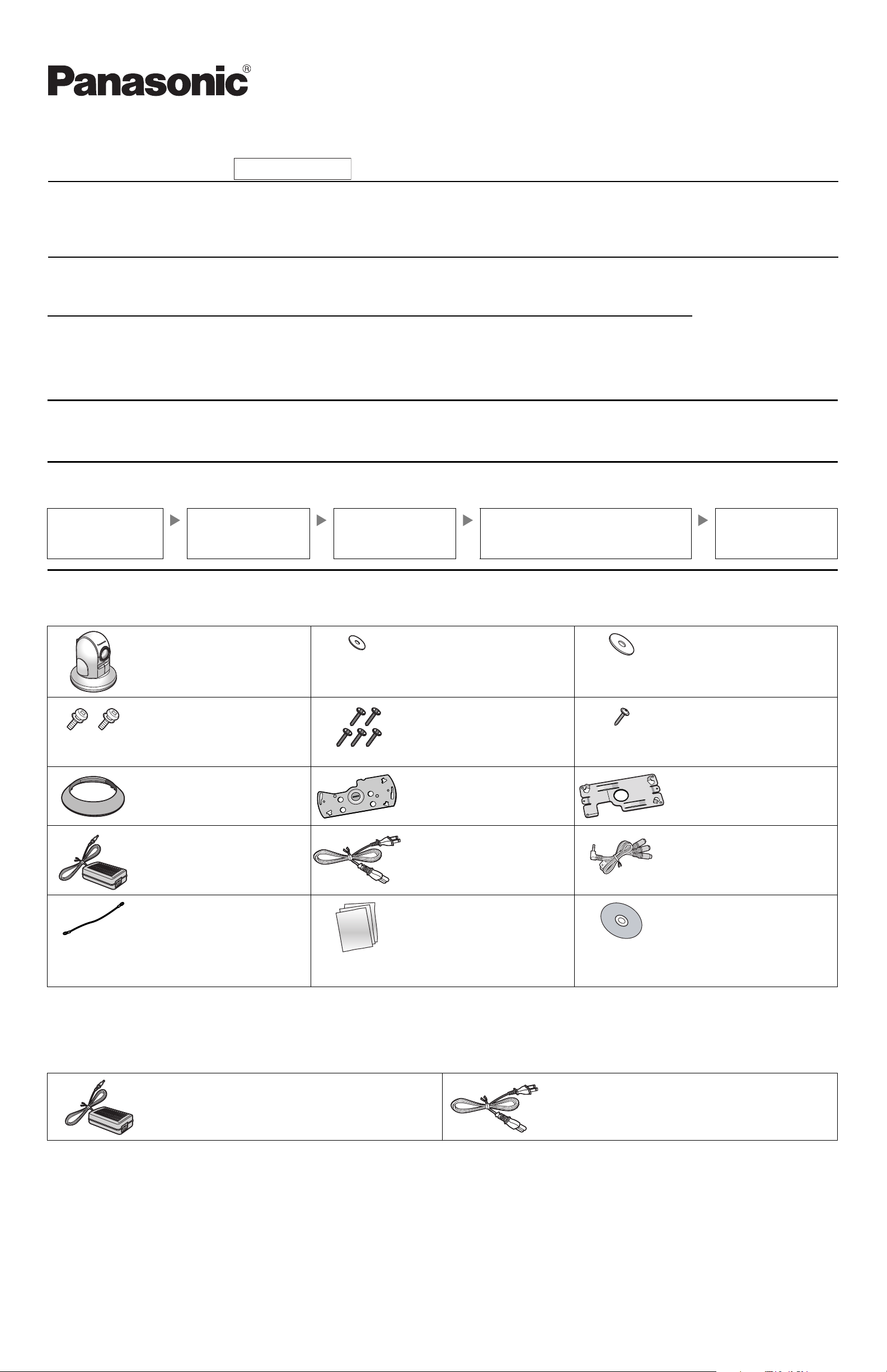
1. Confirm the following items are included in the camera’s packaging.
• Additional pieces can be ordered by calling 1-800-332-5368.
Main Unit (1 pc.) Washer S (1 pc.)
Order No. XWG26D12VW
Used when securing the safety
wire to the camera.
Screw A (2 pcs.)
Order No. XYN3+J6FJ
Used to secure ceiling plate A to
ceiling plate B.
Ceiling Mounting Cover (1 pc.)
Order No. PSKL1023Y2
Used when mounting the camera
on a ceiling.
AC Adaptor (1 pc.)
[BB-HCM580A Only]
Order No. PQLV202U
Cord Length: About 3 m
(9 feet 10 inches)
Safety Wire (1 pc.)
Order No. PQME10080Z
Used to secure the camera when
mounting it.
2. You will need the following additional items to install and configure the camera.
Screw B (5 pcs.)
Order No. XTB4+20AFJ
Used to secure ceiling plate B (4
pcs.) and the safety wire (1 pc.) to
the ceiling.
Ceiling Plate A (1 pc.)
Order No. PQZMHCM581A
Used to secure the camera to
ceiling plate B.
AC Cord (1 pc.)
[BB-HCM580A Only]
Order No. PSJA1069Z
Cord Length: About 1.8 m
(5 feet 11 inches)
Important Information (1 pc.)
Installation Guide
(this document) (1 pc.)
Setup Guide (1 pc.)
Washer L (1 pc.)
Order No. XWG4F16VW
Used when securing the safety
wire to the ceiling.
Screw C (1 pc.)
Order No. PQHV2610PJ65
Used for connecting the safety
wire to the camera.
Ceiling Plate B (1 pc.)
Order No. PQMD10110Z
Used to secure the camera to the
ceiling.
Audio/Video Cord (1 pc.)
[BB-HCM581A Only]
Order No. PSJA1103Y
Setup CD-ROM (1 pc.)
Order No. PQQX15704XCD
Contains the Setup Program needed to
configure the camera, as well as the
camera’s documentation.*
*See the included Important Information
for a description of each document.
– a PC (see the system requirements in the Important Information document) – a LAN cable (CAT-5 straight cable)
– a router
Option for BB-HCM581A
You can also connect the camera using the optional Panasonic BB-HCA3A AC Adaptor. The BB-HCA3A includes the following items.
AC Adaptor (1 pc.)
Cord Length: About 3 m (9 feet 10 inches)
© 2007 Panasonic Communications Co., Ltd. All Rights Reserved.
PQQX15933YA KK0207CM1107
AC Cord (1 pc.)
Cord Length: About 1.8 m (5 feet 11 inches)
1
Page 2
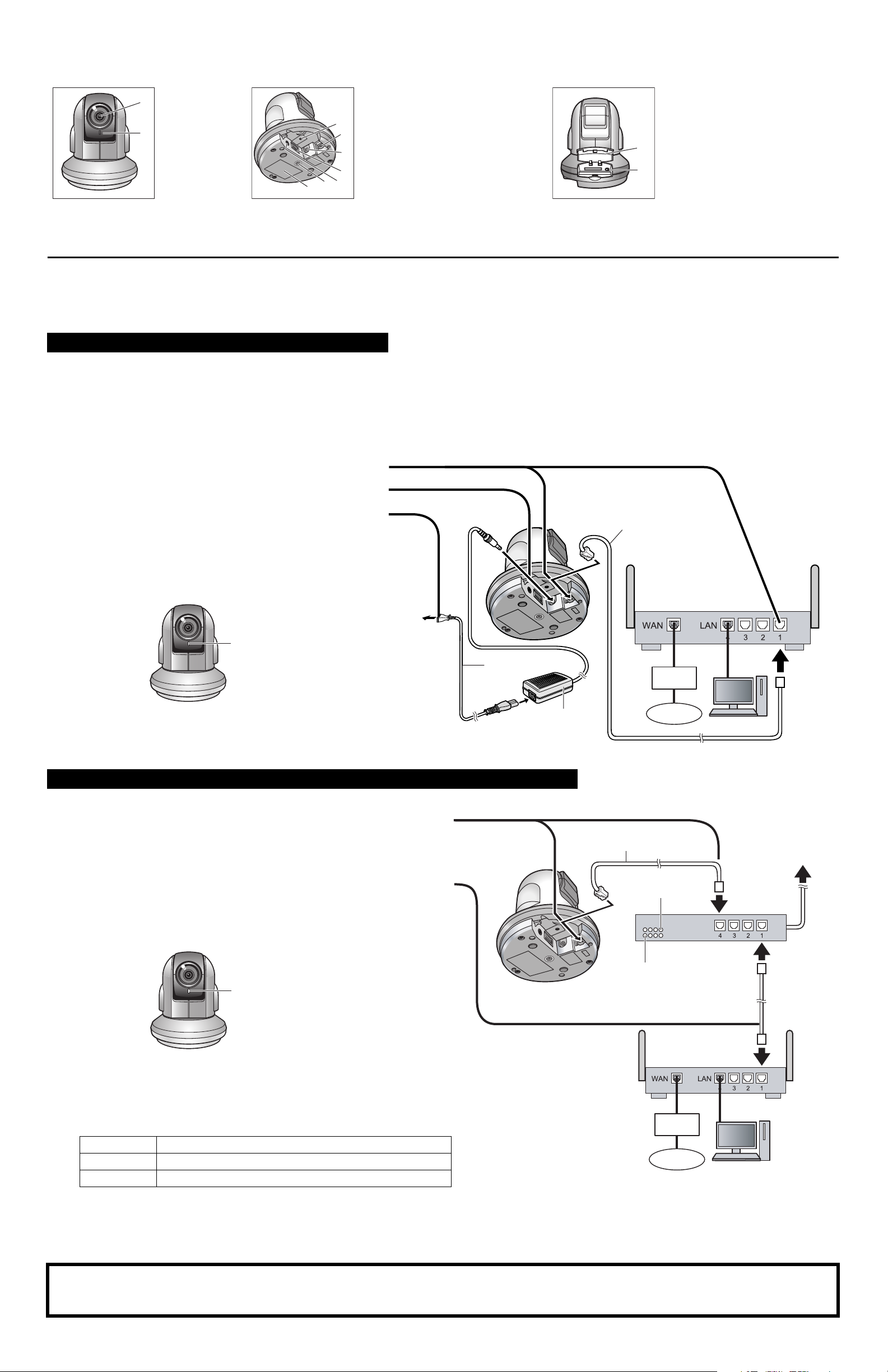
Camera Diagram
Front View Bottom View Rear View
ABLens
A
B
*1 See 1.1 Understanding the Camera Indicator in the Troubleshooting Guide on the CD-ROM for indicator meaning.
Indicator
*1
C
D
E
F
G
H
I
FACTORY DEFAULT RESET
C
button
LAN port
D
DC IN jack
E
External I/O interface
F
BB-HCM580A: Video terminal
G
BB-HCM581A: Audio/video
terminal
Ceiling plate A hole
H
Serial number and MAC address
I
label
JKSD memory card cover
FUNCTION button/indicator
J
K
Connections
Before proceeding, confirm that your PC is connected to your router and can access the Internet. Also confirm that your router’s UPnP™ feature is enabled. (Most
routers have UPnP
(http://panasonic.co.jp/pcc/products/en/netwkcam/) for more information.
When connecting the camera using the AC Adaptor
Follow these instructions when connecting a BB-HCM580A, or when connecting a BB-HCM581A using the optional BB-HCA3A AC Adaptor. Connect the camera
to your router and the power outlet as described below.
™
turned off by default.) Refer to the operating instructions included with your router or to the Panasonic Network Camera website
• BB-HCM580A only: Use only the included Panasonic AC
adaptor (order no. PQLV202U) and AC cord (order no.
PSJA1069Z).
• BB-HCM581A only: If using an AC adaptor, use only the
optional Panasonic AC adaptor BB-HCA3A.
1 Connect the LAN cable to the camera and the router.
2 Connect the AC adaptor cord to the DC IN jack.
3 Connect the AC cord to the AC adaptor, then plug the AC
cord into the power outlet.
• The lens will pan and tilt when the camera is turned on.
• Confirm that the indicator lights green after about 1
minute. If the indicator does not light green, see 1.2
Camera Indicator Issues in the Troubleshooting Guide
on the CD-ROM.
Green
• When you operate the camera, the power outlet should
be near the camera and easily accessible.
• When the lens pans or tilts, a sound can be heard from
the camera. This is normal.
To the
power
outlet
AC cord
AC adaptor
LAN cable
(Cat-5 straight cable)
Router
Modem
Internet
PC
When connecting the camera using PoE (Power over Ethernet) (BB-HCM581A Only)
Connect the camera to your PoE hub using a LAN cable (Cat-5 straight cable) as described below.
1 Connect a LAN cable to the camera and to the PoE hub.
• Your PoE hub must be connected to the router. Refer to the operating
instructions included with the PoE hub for connection instructions.
• The lens will pan and tilt when the camera is turned on.
2 Connect a LAN cable to a LAN port of the PoE hub and to a LAN port of the
router.
• Confirm that the indicator lights green after about 1 minute. If the
indicator does not light green, see 1.2 Camera Indicator Issues in the
Troubleshooting Guide on the CD-ROM.
Green
• When the lens pans or tilts, a sound can be heard from the camera. This
is normal.
• Use a 4-pair UTP/STP cable.
• Do not use a relay connector or a hub between the camera and the PoE
hub. These devices may disturb the data or electricity transmission.
• If the PoE hub has indicators, the indicator lights as shown in the table
below.
Indicator Description
LINK
PoE
Turns on when the data is transmitted from the camera.
Turns on when the electricity is supplied to the camera.
LAN cable
(Cat-5 straight cable)
PoE indicator
LINK indicator
Modem
Internet
To the power
supply
PoE hub
Router
PC
• If the PoE hub is turned off or power supply is temporarily cut off by the
disconnection of the LAN cable, it may take time for the PoE hub’s
indicators to light.
• The indicator display differs depending on manufacturers, refer to the
manuals of the PoE hub.
After the camera’s indicator turns green, you may set up the camera. Continue by following the procedure described in the
included Setup Guide.
• If the indicator does not turn green, see 1.2 Camera Indicator Issues in the Troubleshooting Guide on the included CD-ROM.
2
Page 3

Read the following information after setting up the camera according to the procedure described in the Setup Guide.
Connecting External Sensors
The camera’s external I/O interface allows you to connect 2 devices (such as sensors, motion detectors, etc.) that can be used to trigger the camera’s image
buffering and transferring features (see Section 2 Using Triggers to Buffer and Transfer Images in the Operating Instructions on the CD-ROM).
The external I/O interface has 6 terminals.
External I/O interface
Terminal Description
G GND terminal.
1
G GND terminal.
2
3
4
External sensor input 1. The camera can be triggered by either an open
circuit or a GND short-circuit.
External sensor input 2. The camera can be triggered by either an open
circuit or a GND short-circuit.
External device control output. Allows you to control an external device
using the output buttons in the camera’s operation bar (for example,
turning a light on or off).
• This terminal’s behavior can be changed (see 7.4 Controlling the
External Output Terminal in the Operating Instructions on the CDROM).
• This terminal is an open collector circuit. The maximum drawing
current is the same as terminal 4. Do not exceed the voltage of the
terminal 4.
DC power output terminal.
• 10.5–13 V DC
• Maximum load drive is 100 mA.
Note
• Do not push strongly on the external I/O interface with the pointed object. The
external I/O interface may get stuck into the unit, and you may not be able to
use it.
Circuit Diagram Example
Camera
12 V*
4
3
2
G
1
G
*DC 10.5 V–13 V
Relay
Door Sensor 2 (Alarm 2)
Door Sensor 1 (Alarm 1)
Light
Caution
• The external I/O interface is not capable of connecting directly to devices
that require large amounts of current. In some cases, a custom interface
circuit (customer-provided) may have to be used. Serious damage to the
camera may result if a device that exceeds its electrical capability is
connected to the external I/O interface.
• Low voltage/current circuits and high voltage/current circuits are used in
the camera circuit. All wiring should be performed by a qualified
electrician. Incorrect wiring could damage the camera and cause a fatal
electric shock.
• External devices connected to the camera’s output terminals cannot be
controlled in the event of a network error or failure. Keep this in mind when
connecting door locks, heat-emitting devices, or other devices that may
be dangerous if they cannot be controlled.
Connecting a Video Device (BB-HCM580A Only)
You can connect a TV or other video device (NTSC or PAL format) to the camera to monitor or record camera images. Connect the video device as shown below.
Composite video connector
To T V
Video cable
(customer-provided)
3.5 mm L-type (right angle) connector
Video terminal
Connecting Audio/video Devices (BB-HCM581A Only)
You can connect an external microphone and external speaker to the camera to use the Listen and Talk features, respectively. For information about these
features, see 1.2.10 Audio Features in the Operating Instructions on the CD-ROM. You can also connect a TV or other video device (NTSC or PAL format) to the
camera to monitor or record camera images. Connect the devices as shown below.
Microphone cable
( 3.5 mm mini plug)
Speaker cable
( 3.5 mm stereo mini plug)
For speaker (red)
(Output impedance
560 line level)
For microphone (white)
(Plug-in power +3.3 V)
To speaker To TV
To microphone
Audio/video terminal
Video cable
For TV (yellow)
Audio/video cord
Note
• Analog video output is disabled by default. See 7.5 Controlling the Analog
Video Output Signal in the Operating Instructions on the CD-ROM for more
information.
• If you use an external microphone, excessive cable length or a poor quality
cable can cause degradation in audio quality.
• The microphone cable should be no longer than 7 m (23 feet).
• Use a speaker with a built-in amplifier. The speaker connects to the camera with a
stereo audio cable similar to that used by your PC. The output signal is mono.
• Make sure the camera and speaker are turned off when connecting or
disconnecting the speaker cable, otherwise noise may be heard from the
speaker.
• The external microphone input does not correspond to a line level. Audio may
be distorted when the line level is input. Audio distortion will be solved if you
insert the following circuits. Under no circumstance should high-level audio,
such as from a speaker, be connected to this input terminal. Doing so is likely
to damage the camera.
CapacitorResistor
Camera
Microphone Input
33 K
1 F
Audio Line
Out
3
Page 4

Important Information Regarding Camera Mounting
p
The camera can be mounted on a ceiling or table. Please read the following
information before mounting the camera. Consult an authorized dealer for
mounting.
Caution
• Make sure you attach the safety wire when mounting the camera on a
ceiling to prevent the camera from falling.
Note
• The camera is intended for indoor use only and should not be mounted
outdoors.
• Use screws that are appropriate for the material of ceiling.
• The included screws are for use with wooden ceilings only.
• To ensure that camera images are displayed properly, do not mount the
camera on an incline. Mount the camera so that it is perpendicular to the
floor.
• When the camera is mounted on a ceiling, the ceiling mounting cover must
be removed in order to insert or remove the SD memory card.
• The camera’s MAC address and serial number are printed on the bottom of
the camera and are needed in order for camera configuration and
maintenance. Make a note of both of them for before mounting the camera.
• Mounting and cabling instructions described in this document follow
generally accepted guidelines suitable for residential installations. In some
areas, commercial and industrial installations are regulated by local or state
ordinances. For such installations, contact your local building department or
building inspector for more details.
• Camera images can be viewed in relatively dark areas, however, image
quality decreases when viewing dark images. We recommend using
supplemental lighting for best results.
• Prolonged exposure to direct sunlight or halogen light may damage the
camera’s image sensor. Mount the camera appropriately.
• When mounting the camera, make sure to wrap the AC adaptor cord (if
used) and other cables (external microphone or speaker cable, video cable,
etc.) around the hooks as shown to ensure secure connections.
5. If you plan to run the cables above the ceiling, make a 30 mm (1 3/16
inch) hole in the ceiling, as shown. Run all necessary cables (AC adaptor,
LAN, audio/video, etc.) through the hole.
• The center of the hole should be at the point where the 2 lines on ceiling
plate A would intersect, as shown.
Lines
6. Connect all necessary cables (AC adaptor, LAN, audio/video, etc.).
7. Attach ceiling plate A to ceiling plate B by aligning the 3 tabs as shown,
then turning ceiling plate A counter-clockwise until the tabs are secured.
Secure the plates using screws A (included).
Three tabs
Fit the tabs to the holes and
1
move counterclockwise.
2
Attach firmly with Screws A.
Screws A (2 pcs.)
• The camera should be mounted so that the SD memory card cover
faces the front of the camera (i.e., the same direction as the lens).
8. Attach the ceiling mounting cover by first aligning the “ ” mark on the
camera and cover, then turn the cover clockwise until the “ ” mark on the
camera and the “ ” mark on the cover are aligned as shown.
Hook for AC adaptor cord
Mounting the Camera on a Ceiling
1. Access the camera and set the [Mounting Type] setting to [On the ceiling]
(see 5.4 Changing Basic Camera Settings in the Operating Instructions
on the included CD-ROM). The camera lens will change direction as
shown below.
[On the table]
2. Secure the safety wire to the camera using screw C (included) and
washer S (included).
• Make sure you attach the safety wire when mounting the camera on a
ceiling to prevent the camera from falling.
[On the ceiling]
Screw C
Washer S
Safety wire
Safety wire hole
• Be careful not to nip the cable etc.
• When removing the Ceiling Mounting Cover, move it in the
counterclockwise direction. Adjust both “ ” and let down the main unit.
• If you did not make a hole in the ceiling for the cables, remove the tab
on the ceiling mounting cover and pass the cables through the opening
as shown.
9. Secure the safety wire to the ceiling using screw B (included).
• Secure the safety wire to the ceiling about 100 mm (3 15/16 inches)
from the center of ceiling plate B.
• Do not drive the screw into a soft material. Drive the screw into a
secure, 25 mm (1 inch) thick area of the ceiling, such as a crossbeam,
otherwise the camera may fall. If there is no crossbeam, place a board
on the other side of the ceiling to make sure the camera is securely
mounted.
3. Attach ceiling plate A (included) to the camera by aligning it as shown.
Secure the plate to the camera firmly.
Fit the two dents in place.
Fit the two rubbers in
lace.
4. Secure ceiling plate B (included) to the ceiling using screws B (included).
• Make sure there is at least 100 mm (3 15/16 inches) of space, with no
obstacles, from the center of the plate.
• Do not drive the screws into a soft material. Drive the screws into a
secure, 25 mm (1 inch) thick area of the ceiling, such as a crossbeam,
otherwise the camera may fall. If there is no crossbeam, place a board
on the other side of the ceiling to make sure the camera is securely
mounted.
Keep more than 100 mm (3 15/16 inches)
Camera direction
off the wall or other obstacles.
Washer L
Screw B
When mounting the camera on a concrete or mortar ceiling
1. Place ceiling plate B against the ceiling and mark the points where you
are going to make holes.
2. Make holes with an electric drill. Insert anchors (customer-provided) into
the holes and push them inside the holes with a hammer.
• Mortar ceilings break easily when drilling. Be careful of pieces of mortar
which may become loose and fall.
Drill for concrete (in case of tile, use a drill for tile)
3. Mount the camera by following the instructions on this page.
Mounting the Camera on a Table
Mount or place the camera on a secure and even surface where there are few
vibrations.
4
100 mm
(3 15/16 inches)
Screws B (4 pcs.)
 Loading...