

Page 1
Getting Started
Network Camera
Indoor Use Only
Model No. BB-HCM381A (AC Adaptor Type)
BB-HCE481A (PoE Type)
Trademarks
• Adobe, Acrobat and Reader are either registered trademarks or trademarks of
Adobe Systems Incorporated in the United States and/or other countries.
• Microsoft, Windows and ActiveX are either registered trademarks or trademarks of
Microsoft Corporation in the United States and/or other countries.
• This software is based in part on the work of the Independent JPEG Group.
• Screen shots reprinted with permission from Microsoft Corporation.
• All other trademarks identified herein are the property of their respective owners.
Abbreviations
• UPnP is the abbreviation for "Universal Plug and Play".
• "Network Camera" is called "Camera" in this manual.
• "Setup CD-ROM" is called "CD-ROM" in this manual.
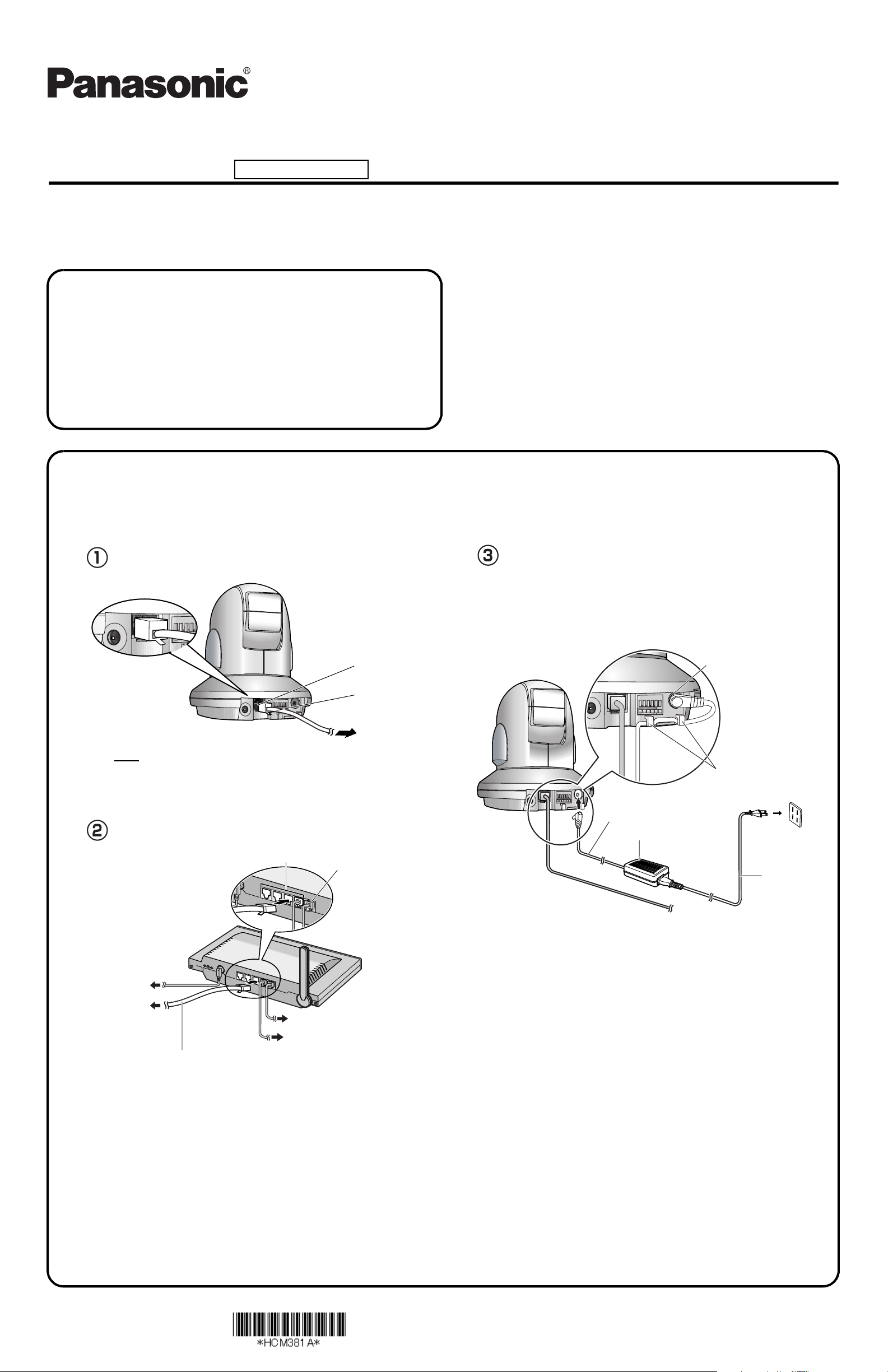
1.Connect the camera (BB-HCM381A), and turn the camera on.
Connect the camera to your router using a "straight" Cat5 Ethernet cable (customer-provided) to set up the camera.
• Before you begin the installation, the UPnP
http://panasonic.co.jp/pcc/products/en/netwkcam/ or contact your router's manufacturer.
™
feature in your router needs to be enabled. Usually, the default setting disables this feature. For more info, please visit,
This manual is for both BB-HCM381A (AC Adaptor Type) and BBHCE481A (PoE Type). Available features and operations are different in
part depending on the model. Read the Operating Instructions on the
CD-ROM carefully and use the Network Camera properly.
BB-HCM381A User: See below.
BB-HCE481A User: Go to page 2.
Please read the Important Information before using.
• This Getting Started explains how to connect and set up the camera.
See Installation Guide for mounting, and see the Operating
Instructions on the CD-ROM for details about the camera’s features.
• If you cannot complete the setup, see the Troubleshooting on the
CD-ROM.
Connect the Ethernet cable (customer-provided) to the
camera.
Ethernet (LAN) port
Ethernet cable
(customer-provided)
To the network
Note
• These instructions assume your PC is already connected to the Internet and
your network includes a router that is UPnP
compliant.
™
(Universal Plug and Play)
Connect the Ethernet cable (customer-provided) to your
router.
LAN ports
WAN port
Connect the AC adaptor cord to the DC IN jack, and plug the
AC cord into the outlet.
• When you operate the camera, the power outlet should be near the camera and
easily accessible.
• Use only specified Panasonic AC adaptor PSLP1242 (Order No. PSLP1242Y).
• If the camera's indicator does not light green, see pages 3-4 of the
Troubleshooting on the CD-ROM.
• A noise can be heard during pan/tilt operation. This is normal.
DC IN jack
Hook for AC adaptor cord
AC adaptor cord
AC adaptor
To the outlet
AC cord
To the supply
To the camera
• When connecting an external microphone, speaker or TV, see page 2.
To your modem
To your PC
A "straight" Cat5 Ethernet cable
(customer-provided)
PQQX15034ZB KK1105RM1056
© 2006 Panasonic Communications Co., Ltd. All Rights Reserved.
Page 2
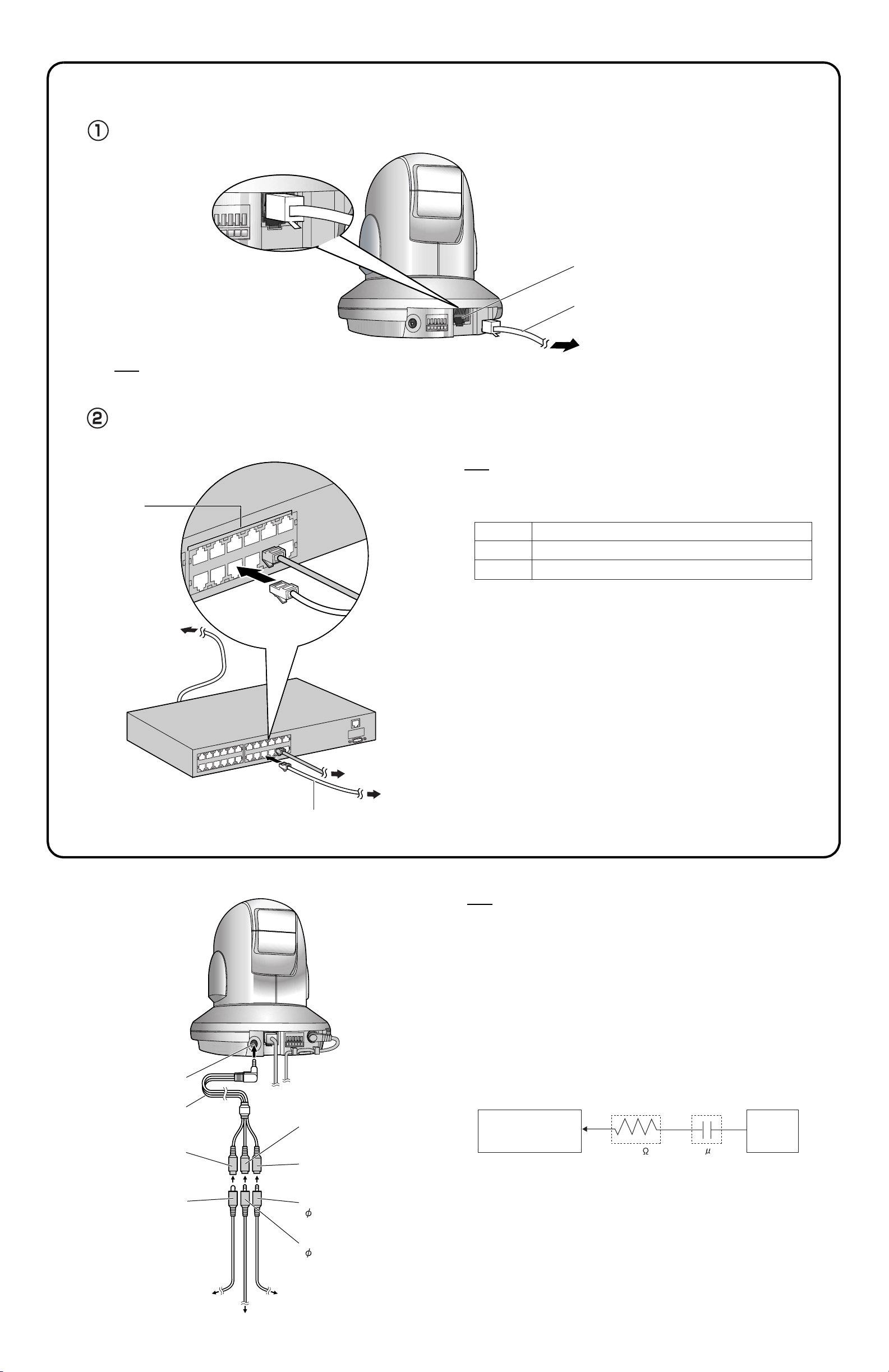
1.Connect the camera (BB-HCE481A), and turn the camera on.
Connect the camera to your PoE (Power over Ethernet) hub using a "straight" Cat5 Ethernet cable (customer-provided) to set up the camera.
Connect the Ethernet cable (customer-provided) to the camera.
PoE IN port
A "straight" Cat5 Ethernet cable
(customer-provided)
To the network
Note
• Your PoE hub must be connected to the router. Refer to the manuals of the PoE hub for the instructions of the connection. Additionally, these instructions assume your PC is
already connected to the Internet and your network includes a router that is UPnP
™
(Universal Plug and Play) compliant.
Connect the Ethernet cable (customer-provided) to your PoE hub.
• If the camera's indicator does not light green, see pages 5-6 of the Troubleshooting on the CD-ROM.
• A noise can be heard during pan/tilt operation. This is normal.
Note
• Use a 4-pair UTP/STP cable.
Ethernet
ports
To the supply
• Do not use a relay connector or a hub between the camera and the PoE hub. These
devices may disturb the data or electricity transmission.
• If the PoE hub has indicators, the indicator lights on as shown in table below.
Indicator
LINK
PoE
• If the PoE hub is turned off or power supply is temporarily cut off by the disconnection
of the Ethernet cable, it may take time for the PoE hub's indicators to light green.
• The indicator display differs depending on manufacturers, refer to the manuals of the
PoE hub.
Description
Turns on when the data is transmitted from the camera.
Turns on when the electricity is supplied to the camera.
To your router
To the camera
A "straight" Cat5 Ethernet cable
(customer-provided)
Connecting an External Microphone, Speaker or TV
Note
• If you use an external microphone, excessive cable length or a poor quality cable can
cause a degradation in audio quality.
• The microphone cable should be no longer than 7 m (23 feet).
• Use a speaker with a built-in amplifier. The speaker connects to the camera with a
stereo audio cable similar to that used by your PC. The output signal is mono.
• Make sure the camera and speaker are turned off when connecting or disconnecting
the Audio/Video Cable or speaker cable, otherwise noise may be heard from the
speaker.
• Use only the included Audio/Video Cable when connecting an external microphone,
speaker, or TV.
• When the camera is in color night view mode, images may not be displayed correctly
on the TV.
• The external microphone input (via the Audio/Video Cable) does not correspond to a
line level. Audio may be distorted when the line level is input. Audio distortion will be
solved if you insert the following circuits. Under no circumstance should high-level
audio, such as from a speaker, be connected to this input terminal. Doing so is likely
to damage the camera.
Camera
Microphone Input
(via Audio/Video Cable)
Audio/Video Terminal
Audio/Video Cable
For TV (yellow)
(The illustration is BB-HCM381A.)
For microphone (white)
(Plug-in power +3.3 V)
For speaker (red)
(Output impedance 560 line level)
Ω
CapacitorResistor
Audio Line
Out
1 F33 K
Video cable
To T V
To microphone
Speaker cable
( 3.5 mm stereo mini plug)
Microphone cable
( 3.5 mm mini plug)
To speaker
2
Page 3
2.
Setting up the Camera to View on the LAN.
Important
• To avoid any possible problems, temporarily disable any firewall
or antivirus software.
• This procedure explains installation of the camera on the same
network as your PC.
• Before proceeding, close your web browser.
• See page 180 of the Operating Instructions on the CD-ROM for
details about CD-ROM.
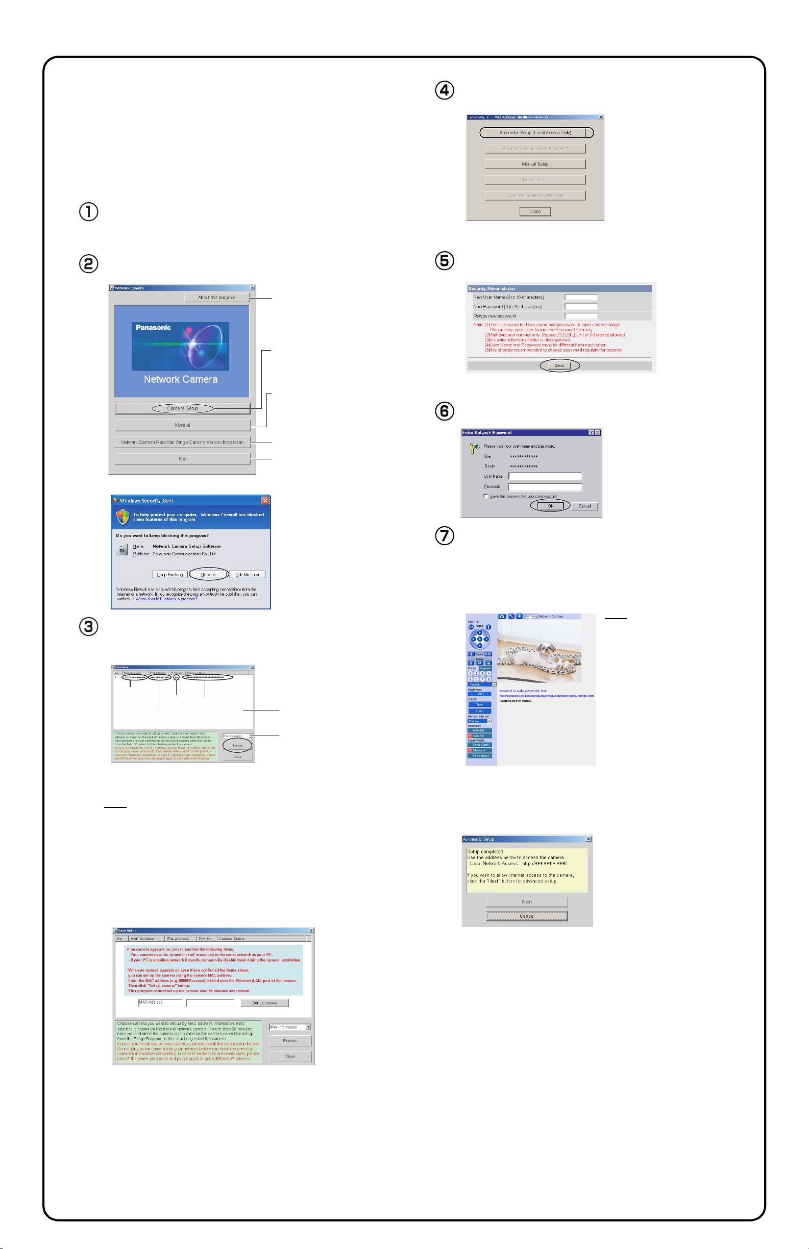
Insert the CD-ROM into the CD-ROM drive of the PC.
Click [Automatic Setup (Local Access Only)].
(If the Network Camera Setup window is not displayed automatically,
double-click the "Setup.exe" file on the CD-ROM.)
Click [Camera Setup].
Displays version information
about this program.
Sets up the camera.
Displays the camera manuals.
If your PC does not have Adobe
®
Acrobat
from the Adobe Reader website.
Installs Network Camera
Recorder Single Camera Version.
Closes the Setup Program.
• If a Windows Security Alert is displayed, click [Unblock].
Reader®, download it
• See page 180 of the Operating Instructions on the CD-ROM for manual setup.
Enter the user name and password, and click [Save].
®
• The password must be different from the user name.
• Make a note of the user name and password for the reminder.
The Enter Network Password window is displayed. Enter
the user name and password that were set, and click [OK].
Select the camera to set up and click [Execute].
• This program searches for the cameras that are connected to the router and
displays their MAC Addresses, IP addresses and Port Numbers.
. ..
MAC
Address
• The MAC Address (see page 9 [BB-HCM381A] or page 11 [BB-HCE481A] of
the Operating Instructions on the CD-ROM.) on the bottom of the camera
shows which camera you select on the camera list window.
IP
Address
Port
No.
Camera
Status
Camera List window
Displays IPv4 or
IPv6 information.
Note
• If the indicator does not light green, check the connection (see page 1 [BBHCM381A] or page 2 [BB-HCE481A]).
• If more than 20 minutes have passed since the camera was turned on, the
camera cannot be set up from the Setup Program. In this situation, turn the
camera off, and turn the camera on again.
• The Setup Program may not list any cameras due to your firewall or antivirus
software settings on your PC. If you cannot disable your firewall or antivirus
software, you can set up the camera by entering the camera MAC address on
the following window. The camera's MAC address can be found on the label
affixed to the bottom of each camera. See page 9 [BB-HCM381A] or page 11
[BB-HCE481A] of the Operating Instructions on the CD-ROM for details.
When the Single Camera page is displayed, setup is
complete.
• If the Security Warning window is displayed when installing ActiveX®
Controls, click [Yes].
• To install ActiveX Controls on Microsoft
®
Windows® XP Service Pack
2, see "Security Warning window on Microsoft Windows XP Service
Pack 2" on page 4.
Note
• If the camera cannot be accessed,
see page 9 of the Troubleshooting
on the CD-ROM.
• To ensure that the most current
image is displayed, Internet Explorer
should be configured as follows.
This will not have a negative effect
on normal use.
1. While viewing any website, click
[Tools] → [Internet Options].
2. In the section "Temporary Internet
Files", click [Settings] and check
[Every visit to the page].
To enable Internet access to the camera
Click [Next] to set up the Internet access to the camera and
go to page 4.
. ..
• If you do not allow Internet access, click [Cancel], and see page 17 of the
Operating Instructions on the CD-ROM.
3
Page 4
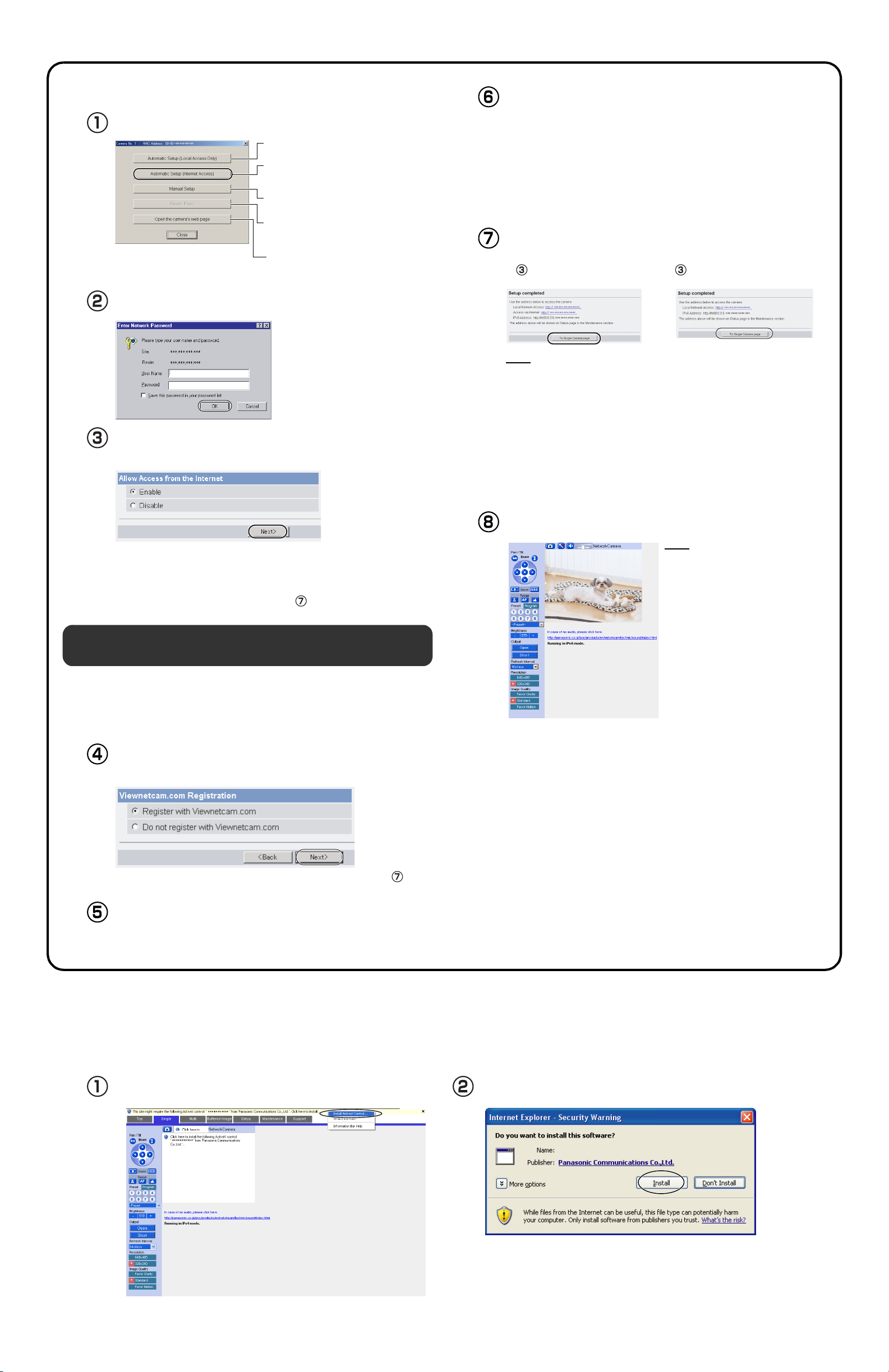
3.Setting up Internet Access to the Camera.
Click [Automatic Setup (Internet Access)].
Sets up the camera to view on the LAN.
Sets up the Internet access to the
camera.
Manually sets up the camera.
Disables IPsec. If disabled, the button is
displayed gray.
Displays the Setup page
(see page 45 of the Operating
Instructions on the CD-ROM).
The Enter Network Password window is displayed. Enter the
user name and password that were set, and click [OK].
When using a router that supports UPnP
When using a router that does not support UPnP
[Disable]. Then click [Next>].
™
, check [Enable].
™
, check
The "Viewnetcam.com FREE DynamicDNS service"
website is displayed. Follow the displayed instructions for
registration.
• If the message "Failed to configure the router's Port Forwarding by UPnP" is
displayed, your router may not support UPnP
Enable your router's UPnP
router's manual, and try Automatic Setup again. For more information about
setting up a router, refer to the Panasonic Network Camera support website at
http://panasonic.co.jp/pcc/products/en/netwkcam/
• If the message "Failed to register with Viewnetcam.com." is displayed, confirm that the router is connected to the Internet.
™
or set Port Forwarding manually following the
™
or UPnP™ is not enabled.
When "Setup completed" is displayed, make a note of the
URL and click [To Single Camera page].
• When [Enable] was selected at step .• When [Disable] was selected at step
.
Note
• The port number must be specified at the end of the camera URL.
For example
Using port 80:
http://(Cameraname).viewnetcam.com or http://IP Address
Using any other port:
http://(Cameraname).viewnetcam.com:Port Number or
http://IP Address:Port Number
• Make a note of the URL for the camera.
• The URL for the local network access may be different from the one set up on
the previous page. Make a note of the URL here again.
• Check if your router supports UPnP™ referring to the router's
manual. If UPnP
™
is not supported, the router has to be manually
configured for port forwarding. Refer to the router's manual for
instruction on how to do it.
• If you select [Disable], skip to step .
Registration with the "Viewnetcam.com FREE
DynamicDNS service"
By registering with the Viewnetcam.com FREE DynamicDNS service,
you can create a personalized web address at which your camera's live
video can always be found on the Internet. For detailed information,
access "http://www.viewnetcam.com".
To register with the "Viewnetcam.com FREE DynamicDNS
service", check [Register with Viewnetcam.com] and click
[Next>].
When the Single Camera page is displayed, the setup is
complete.
Note
• If the camera cannot be accessed,
see page 9 of the Troubleshooting
on the CD-ROM.
• To ensure that the most current
image is displayed, Internet Explorer
should be configured as follows.
This will not have a negative effect
on normal use.
1. While viewing any website, click
[Tools] → [Internet Options].
2. In the section "Temporary Internet
Files", click [Settings] and check
[Every visit to the page].
• If you selected [Do not register with Viewnetcam.com], skip to step .
The Enter Network Password window is displayed. Enter
the user name and password that were set, and click [OK].
Security Warning window on Microsoft Windows XP Service Pack 2
To view a video (Motion JPEG) or to use audio feature, ActiveX Controls must be installed.
Follow the steps below to install ActiveX Controls.
Click the warning displayed above the tabs, and click [Install
ActiveX Control...].
Click [Install].
********
4
Page 5
Installation Guide
Please read the Important Information before using.
Network Camera
Model No. BB-HCM381A (AC Adaptor Type)
Indoor Use Only
BB-HCE481A (PoE Type)
This manual is for both BB-HCM381A (AC Adaptor Type) and BB-HCE481A (PoE Type). Available features and operations
are different in part depending on the model. Read the Operating Instructions on the CD-ROM carefully and use the
Network Camera properly.
Mount the camera after the camera is connected and finished setting up following Getting Started.
Installation Procedures
•
"Network Camera" is called "Camera" in this manual.
•
"Setup CD-ROM" is called "CD-ROM" in this manual.
•
The illustrations used in this manual are of BB-HCM381A.
•
Temporarily place
the camera.
Adjust the position and
direction of the camera.
Attach the camera.
The camera can be viewed in the least light requirement at 3 lx (default). Use supplemental lighting for the dimly lit places.
•
(The camera can be viewed in the least of 0.09 lx in the color night view mode (see page 80 of the Operating Instructions on
the CD-ROM), which may increase the refresh interval.)
After preparing the Ethernet cable that has enough length, mount the camera.
•
Mounting and cabling instructions described in this Installation Guide follow generally accepted guidelines suitable for residential
•
installations. In some areas, commercial and industrial installations are regulated by local or state ordinances. For such installations,
contact your local building department or building inspector for more details.
Mounting on the Ceiling
Make sure the camera is firmly mounted on the ceiling.
•
The camera is available between ±15˚ based on level line
•
for mounting.
The camera should be uninstalled from the ceiling when removing
•
the SD memory card (see page 140 of the Operating Instructions
on the CD-ROM).
The camera is intended for indoor use only. Prolonged exposure
•
to direct sunlight or halogen light may damage CCD.
The camera's MAC address and serial number are printed on the
•
bottom of the camera. They are needed in order for camera
configuration and maintenance. Record both of them for before
mounting the camera.
Set the Mounting type setting to [On the ceiling] on the Camera Setup
•
page (see page 80 of the Operating Instructions on the CD-ROM).
Two ways of wiring can be considered; wiring through a hole made
•
in the ceiling or wiring without making a hole for a cable in the ceiling.
Select either one of the two.
The audio/video cable cannot be connected or removed after
•
mounting on the ceiling.
Temporarily place the camera where you like to view images.
Adjust the position and direction of the camera while you confirm that
images are displayed on the monitor as you imaged.
The camera can be mounted on the ceiling.
Attach the camera firmly when mounting on the ceiling.
Wiring through a hole made in the ceiling
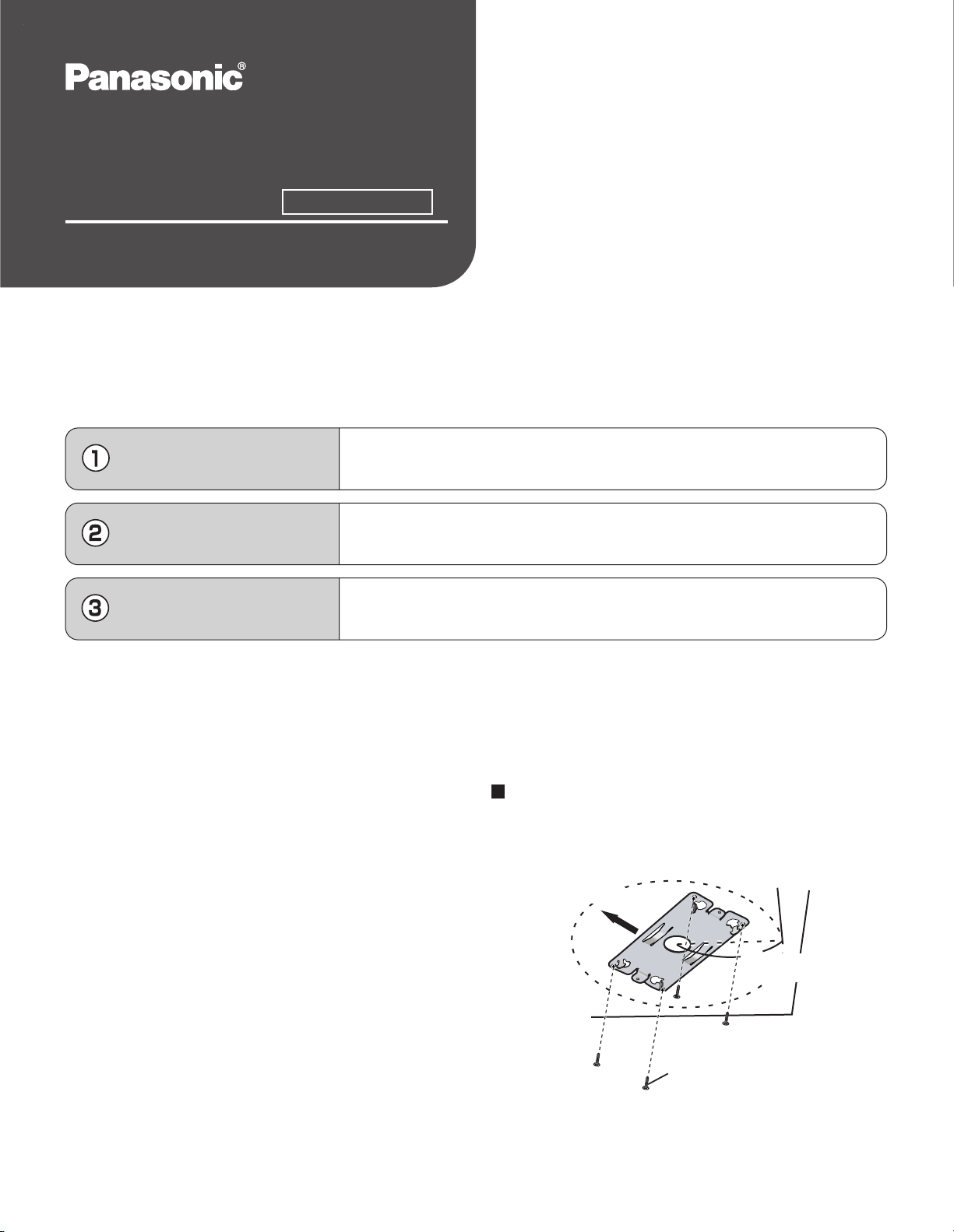
Attach the Ceiling Plate B on the ceiling with Screws B.
1
Keep more than 100 mm
(3 15/16 inches) off the wall
or other obstacles.
Camera direction
100 mm
(3 15/16 inches)
Screws B (4 pcs.)
Attach the Ceiling Plate B more than 100 mm (3 15/16 inches) off
•
the wall or other obstacles from its center.
Make sure the camera is firmly mounted on a beam of wood etc.
•
When there is no beam, apply a board on the other side of the
ceiling to make sure the camera does not drop.
© 2006 Panasonic Communications Co., Ltd. All Rights Reserved.
PQQX15035ZA
KK1105RM0
Page 6
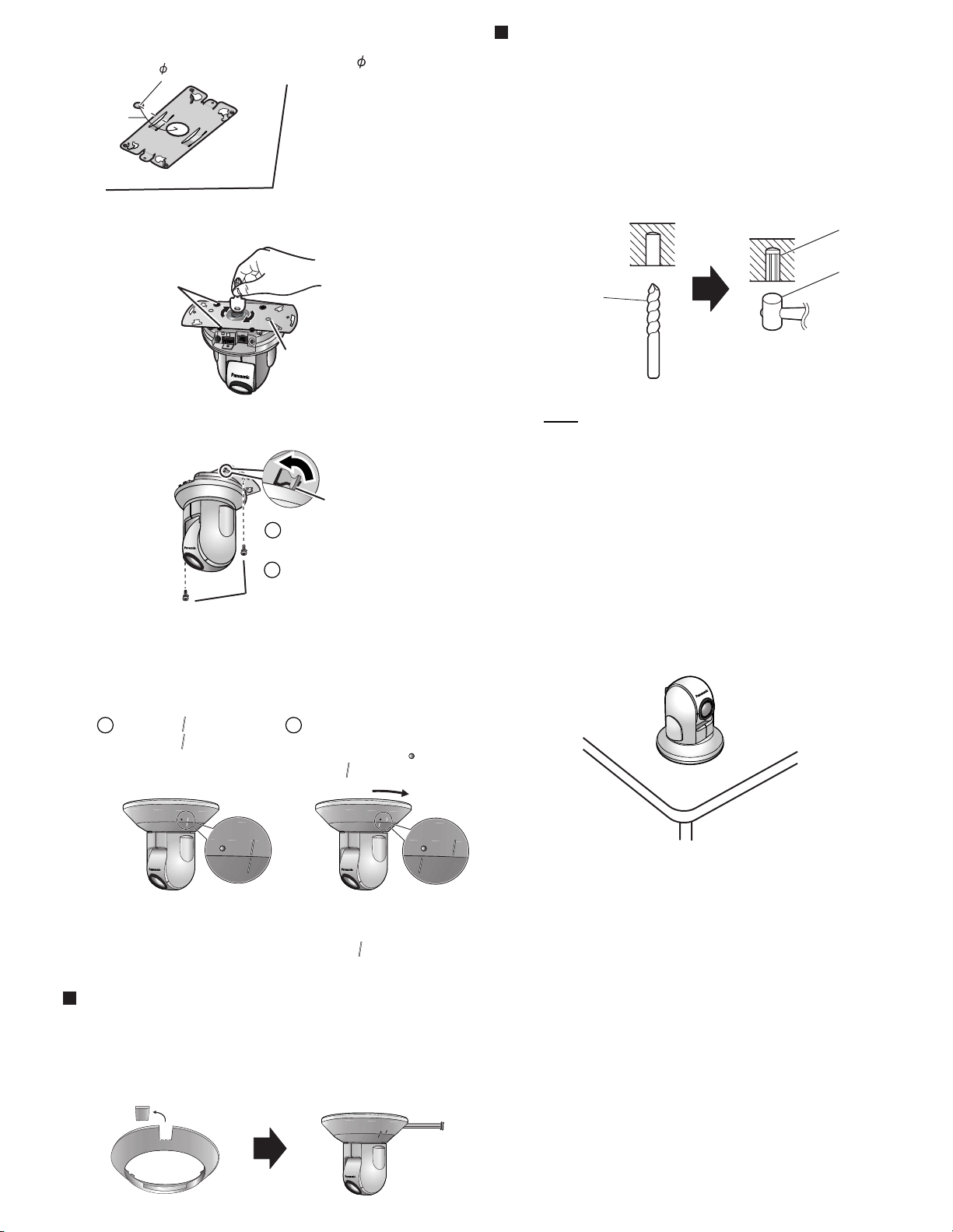
Make a hole for a cable.
2
65 mm
(2 9/16 inches)
Attach the rubbers and dents on the camera to the Ceiling
3
Plate A and attach them firmly.
Hole for a cable
25 mm (1 inch)
Make a 25 mm (1 inch)
•
hole where is 65 mm
(2 9/16 inches) away from
the center in the plate.
Ceiling Mounting when the material of
the ceiling is mortar or concrete
Fit the Ceiling Plate B to the mounting position
1
and put marks.
Make holes at the marks and put plastic plugs
2
(customer-provided) into them.
Plastic plug
Fit the four rubbers
in place.
Fit the two dents in place.
Attach the Ceiling Plate A to the Ceiling Plate B and attach
4
them firmly with Screws A.
Four tabs
Fit the tabs to the holes and
1
move counterclockwise.
2
Attach firmly with Screws A.
Screws A (2 pcs.)
Install the camera so that the connecting part comes
•
to the front.
Connect all necessary cables (AC adaptor cord,
5
Ethernet cable, Audio/Video Cable, etc.) seeing Getting
Started and attach the Ceiling Mounting Cover.
Adjust the " " of the main
1 2
unit to the " " of the Ceiling
Mounting Cover.
Move the Ceiling Mounting
Cover in the clockwise
direction until the " " of it fits
to the " " of the main unit.
Drill for concrete
(in case of tile,
use a drill for tile)
Note
When drilling into mortar, be careful of pieces of mortar
•
which may become loose and fall.
Mount the camera.
3
Mounting on the Table
Mount the camera at an even place on the table where
vibrations etc. are few.
Soft hammer
Be careful not to nip the cable etc.
•
When removing the Ceiling Mounting Cover, move it in the
•
counterclockwise direction. Adjust both " " and let down the
main unit.
Wiring without making a hole for a cable
in the ceiling
Follow the steps 1), 3), 4) and 5). Making a hole is not necessary.
Remove the tab of Ceiling Mounting Cover and wire
•
through the notch.
Set the Mounting type setting to [On the table] on the
•
Camera Setup page (see page 80 of the Operating
Instructions on the CD-ROM).
Page 7
Important Information
Network Camera
Model No. BB-HCM381A (AC Adaptor Type)
Indoor Use Only
BB-HCE481A (PoE Type)
This manual is for both BB-HCM381A (AC Adaptor Type) and BBHCE481A (PoE Type). Available features and operations are different
in part depending on the model. Read the Operating Instructions on
the Setup CD-ROM carefully and use the Network Camera properly.
Please read this manual before using, and save this manual for future
reference.
Panasonic Network Camera Website:
http://www.panasonic.com/netcam
How to Use This Documentation
The Network Camera includes the following 5 manual types.
• Important Information (This manual)
This manual has general information and safety instructions you will
need to understand before installing.
• Getting Started
Getting Started explains the initial configuration of the Network
Camera, to help you to set up the Network Camera quickly and easily.
• Installation Guide
Installation Guide explains mounting methods of the Network Camera.
• Operating Instructions (Included on the Setup CD-ROM)
Operating Instructions explains the operations, settings, features and
maintenance of the Network Camera.
• Troubleshooting (Included on the Setup CD-ROM)
Troubleshooting provides troubleshooting help.
Trademarks
• Microsoft and Windows are either registered trademarks or trademarks
of Microsoft Corporation in the United States and/or other countries.
• Pentium is a trademark or registered trademark of Intel Corporation or its
subsidiaries in the United States and other countries.
• All other trademarks identified herein are the property of their respective
owners.
Abbreviations
• "Network Camera" is called "Camera" in this manual.
• "Setup CD-ROM" is called "CD-ROM" in this manual.
IMPORTANT SAFETY INSTRUCTIONS
When using this unit, basic safety precautions should always be followed
to reduce the risk of fire, electric shock, or personal injury.
1. Read and understand all instructions.
2. Keep these instructions.
3. Heed all warnings.
4. Follow all instructions.
5. After taking away the sand or the dust on the lens, wipe the lens with
6. Do not block any ventilation openings. Install in accordance with the
7. Do not install near any heat sources such as radiators, heat registers,
8. [For BB-HCM381A] Protect the AC adaptor cord and AC cord from
9. [For BB-HCM381A] When you operate the camera, the power outlet
10. Only use attachments/accessories such as stand specified by the
11. Do not touch the unit, Ethernet cable, AC adaptor, AC adaptor cord
12.
13. Refer all servicing to qualified service personnel. Servicing is required
14. Prolonged exposure to direct sunlight or halogen light may damage
15. The camera is intended for indoor use only.
16. Keep the SD memory card (customer-provided) out of reach of
17. Unplug this unit from power supply if it emits smoke, an abnormal
SAVE THESE INSTRUCTIONS
lens cleaning paper.
manufacturer's instructions.
stoves, or other devices (including amplifiers) that produce heat.
being walked on or pinched particularly at plugs, convenience
receptacles, and the point where they exit from the unit.
should be near the camera and easily accessible.
manufacturer.
and AC cord during lightning storms.
Unplug the unit from power supply when unused for long periods of time.
when the unit has been damaged in any way, such as the AC adaptor,
AC cord or plug is damaged, the unit does not operate normally, or
has been dropped.
CCD sensor.
children to prevent swallowing.
smell or makes unusual noise. These conditions can cause fire or
electric shock. Confirm that smoke has stopped and contact an
authorized service center.
FCC and Other Information
This equipment has been tested and found to comply with the limits for a Class B digital device, pursuant to Part 15 of the FCC Rules. These limits are
designed to provide reasonable protection against harmful interference in a residential installation. This equipment generates, uses and can radiate radio
frequency energy and, if not installed and used in accordance with the instructions, may cause harmful interference to radio communications.
However, there is no guarantee that interference will not occur in a particular installation. If this equipment does cause harmful interference to radio or
television reception, which can be determined by turning the equipment off and on, the user is encouraged to try to correct the interference by one or
more of the following measures:
• Reorient or relocate the receiving antenna.
• Increase the separation between the equipment and receiver.
• Connect the equipment into an outlet on a circuit different from that to which the receiver is connected.
• Consult the dealer or an experienced radio/TV technician for help.
This device complies with Part 15 of the FCC Rules. Operation is subject to the following two conditions:
(1) This device may not cause harmful interference, and (2) this device must accept any interference received, including interference that may cause
undesired operation.
Environment:
Do not install the camera where the temperature is less than 0 °C (+32 °F) or greater than +40 °C (+104 °F). Allow 10 cm (3 15/16 inches) clearance
around the unit for proper ventilation. Avoid excessive smoke, dust, mechanical vibration, shock, or direct sunlight.
Routine care:
Wipe the unit with a soft cloth. Do not use benzine, thinner, or any abrasive powder.
When you leave the unit unused for a long period of time, disconnect the plug of the AC cord from the outlet (BB-HCM381A) or disconnect the Ethernet
cable from the unit (BB-HCE481A).
If you have any problems:
Consult an authorized Panasonic Factory Service Center.
CAUTION:
Any changes or modifications not expressly approved by the party responsible for compliance could void the user's authority to operate this device.
No responsibility will be taken by our company with respect to consequences resulting from the use, damage or both of the camera.
CR Coin Cell Lithium Battery Information:
This product contains a CR Coin Cell Lithium Battery which contains Perchlorate Material - special handling may apply.
See www.dtsc.ca.gov/hazardouswaste/perchlorate.
Audio and Video Recording Notice
PLEASE NOTE that under certain circumstances, audio/video recording may be PROHIBITED by law. This device should be used only in compliance with
all applicable laws and statutes.
© 2006 Panasonic Communications Co., Ltd. All Rights Reserved.
PQQX15033ZB KK1105RM1056
Page 8
System Requirements for your PC
Security Cautions
Your PC (Personal Computer) and network must meet the following
technical specifications for the camera to work properly.
For IPv4 Connection
Item Description
Operating
System
Microsoft
Microsoft
®
Windows® XP, Microsoft® Windows® 2000
®
Windows® Me, Microsoft® Windows® 98SE
CPU • For viewing single camera
Pentium
®
III (800 MHz or greater is recommended.)
• For viewing multiple cameras
Pentium
®
4 (1.8 GHz or greater is recommended.)
Protocol TCP/IP protocol
(HTTP, TCP, UDP, IP, DNS, ARP, ICMP)
Interface 10/100 Mbps network card installed
Web Browser Internet Explorer 6.0 or later
(Not included on the CD-ROM)
Audio User-supplied microphone and speaker (required to use
the Talk and Listen features)
For IPv6 Connection
Item Description
Operating
Microsoft
System
CPU • For viewing single camera
Pentium
• For viewing multiple cameras
Pentium
Protocol TCP/IP protocol
(HTTP, TCP, UDP, IP, DNS, ICMPv6, NDP)
Interface 10/100 Mbps network card installed
Web Browser Internet Explorer 6.0 or later
(Not included on the CD-ROM)
®
Windows® XP Service Pack 1 or later
®
III (800 MHz or greater is recommended.)
®
4 (1.8 GHz or greater is recommended.)
When using this product, take appropriate measures to avoid the following
security breaches.
• Leaks of private information via this product
• Illegal use of this product by a third party
• Interference or suspension of the use of this product by a third party
Take the following measures to avoid security breaches:
• To prevent illegal access, keep the firmware up to date
(If you do not have the latest version of firmware, this can lead to
blocked access or information leaks).
• You are responsible for the security settings, such as user name and
password, to access this product. This information should not be made
available to any third parties outside the user group.
• Mount the camera where the camera will not be stolen.
• You are responsible for this product's user information, such as videos,
still images, Internet content, etc. This information should not be made
available to any third parties outside the user group.
• When sending this product to be repaired with a company not related to
Panasonic, make back-up copies of files, if necessary, and reset this
product to factory default.
• When transferring this product to another party, make back-up copies of
files, if necessary, and reset this product to factory default.
• Recorded files stored on the SD memory card can lead to private
information leaks. When sending this product to be repaired or
transferring it to another party, ensure that the SD memory card is
removed.
• When disposing of this product, reset this product to factory default, or
erase information by means of electrical deletion or physical
dismantlement.
User Name and Password Protection
The use of a unique User Name and secret Password is an important
tool that will help limit unauthorized individuals from accessing the
camera. If you choose to disable this tool, and choose not to limit
access by use of a User Name and Password, this may result in
access to the camera by unauthorized individuals. (See page 88 of
the Operating Instructions on the CD-ROM)
Audio User-supplied microphone and speaker (required to use
the Talk and Listen features)
Note
• A PoE hub is required for BB-HCE481A.
• See Panasonic Network Camera support website at
http://panasonic.co.jp/pcc/products/en/netwkcam/ for details about
network environment.
What is IPv6?
• IPv6 is short for "Internet Protocol Version 6".
• IPv6 was created to provide the additional IP addresses that will be
needed as the Internet continues to expand.
• IPv6 is expected to gradually replace IPv4, with the 2 coexisting for a
number of years during a transition period.
• Though most ISPs (Internet Service Providers) do not yet support IPv6,
many local networks already use it. When your ISP supports IPv6, your
Panasonic Network Camera will be ready!
• For more information, visit http://www.ipv6.org/.
For product service
• Panasonic Servicenters are listed in the servicenter directory.
• Call 1-800-272-7033 for the location of an authorized servicenter.
• This Network Camera is designed for use in the United States of America. Sale or use
of this product in other countries/areas may violate local laws.
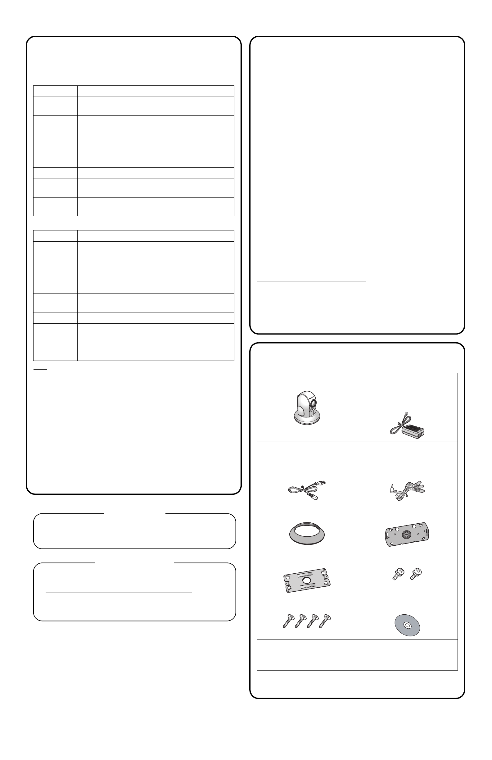
Included Items
The following items are provided with the camera.
Main Unit*1. . . . . . . . . . . . . . .1 pc. AC Adaptor [BB-HCM381A Only]
. . . . . . . . . . . . . . . . . . . . . . . . 1 pc.
Order No.: PSLP1242Y
Cord Length: About 3 m (9 feet 10
inches)
AC Cord [BB-HCM381A Only]
. . . . . . . . . . . . . . . . . . . . . . . .1 pc.
Order No.: PSJA1069Z
Cord Length: About 1.8 m (5 feet 11
inches)
Ceiling Mounting Cover . . . .1 pc.
Order No.: PSKL1023Y2
Audio/Video Cable . . . . . . . . 1 pc.
Order No.: PSJA1103Z
Cord Length: About 48 cm (1 feet 7
inches)
Ceiling Plate A . . . . . . . . . . . 1 pc.
Order No.: PSZMHCM381A
When you ship the product
• Carefully pack your unit, preferably in the original carton.
• Attach a letter, detailing the symptom, to the outside of the carton.
Symptom
• Send the unit to an authorized servicenter, prepaid and adequately insured.
• Do not send your unit to the Panasonic Consumer Electronics Company listed below
or to executive or regional sales offices. These locations do not repair consumer
products.
The information in this document is subject to change without notice.
Panasonic Consumer Electronics Company,
Division of Panasonic Corporation of North America
One Panasonic Way, Secaucus, NJ 07094
Panasonic Puerto Rico, Inc.
San Gabriel Industrial Park, Ave. 65 de Infantería, Km. 9.5,
Carolina, Puerto Rico 00985
Copyright:
This material is copyrighted by Panasonic Communications Co., Ltd., and may be reproduced for internal
use only. All other reproduction, in whole or in part, is prohibited without the written consent of Panasonic
Communications Co., Ltd.
Ceiling Plate B. . . . . . . . . . . .1 pc.
Order No.: PSMD1045Y
Screws B . . . . . . . . . . . . . . .4 pcs.
Order No.: XTB4+20AFJ
Important Information
(This manual). . . . . . . . . . . . .1 pc.
Getting Started . . . . . . . . . . .1 pc.
Installation Guide . . . . . . . . .1 pc.
*1The BB-HCM381A rear view is different from the BB-HCE481A rear view
(see page 9 [BB-HCM381A] or page 11 [BB-HCE481A] of the Operating
Instructions on the CD-ROM).
Screws A . . . . . . . . . . . . . . . 2 pcs.
Order No.: XYN3+J6FJ
Setup CD-ROM . . . . . . . . . . . 1 pc.
Order No.: PQQX15036ZCD
Page 9

Operating Instructions
Network Camera
Model No. BB-HCM381A
BB-HCE481A
Indoor Use Only
(AC Adaptor Type)
(PoE Type)
Please read this manual before using, and save this manual for future reference.
Panasonic Network Camera Website: http://www.panasonic.com/netcam
for customers in the USA or Puerto Rico
Page 10

Operating Instructions
Main Features
This manual is for both BB-HCM381A (AC Adaptor Type) and BB-HCE481A
(PoE Type). Available features and operations are different in part depending
on the model. Read this manual carefully and use the Network Camera
properly.
IPv6*1 Network Camera
Your Panasonic Network Camera supports IPv6 (Internet Protocol Version 6). IPv6
was created to address the additional IP addresses that will be needed as the
Internet continues to expand. Since the camera also supports the currently used
IPv4, its "dual stack" design will seamlessly operate while IPv6 is phased in. For
more information regarding IPv6, see page 15, or visit http://www.ipv6.org/.
PoE (Power over Ethernet) Supported*2 (For Only BB-HCE481A [PoE Type])
The camera supports PoE (Power over Ethernet), and be powered up by using an
Ethernet cable without the AC adaptor.
Audio 2-way Communication*3 (Walkie-talkie Type)
2-way audio communication is now possible between your Network Camera and
PC. By connecting a user-supplied microphone and speaker*4 to both the camera
and to the PC, you will be able to speak to and hear anyone within range of the
camera.
For example, the camera can be used in the following various locations:
• In the baby's room, to hear if the baby is crying.
• At the front door, to see and hear who is at the door.
• In the children's play room, to see and hear if they are safe.
Note
• PLEASE NOTE that under certain circumstances, audio/video recording may
be PROHIBITED by law. This device should be used only in compliance with all
applicable federal, state and local statutes.
*1
To connect using IPv6, subscribe to your ISP's "IPv4/IPv6 Dual-Stack" or "IPv6 over IPv4
Tunneling" service. The camera does not function on IPv6-only networks.
*2
BB-HCE481A works with a PoE hub only. No port for AC adaptor.
*3
The audio feature does not work well on cell phones. The Talk button and Listen button cannot
be used simultaneously. Depending on the network environment and traffic conditions, the
audio may be delayed or may break up.
*4
The speaker connected to the camera requires a built-in amplifier.
2
Page 11

Operating Instructions
Motion Detection
The camera has a Motion Detection feature that detects movement, such as
people, based on the preset threshold and sensitivity of the camera.
You can buffer the camera images, transfer images to an FTP server or send Emails using the Motion Detection function as a trigger.
Better Image Quality
The CCD sensor and the color night view mode provides better image quality and
low light performance.
• The CCD sensor gives you clear image.
• You can monitor live video (Motion JPEG) that refreshes its image 30 frames
per second.
• Color night view mode allows you to monitor the camera in low illuminance.
Remote Pan/Tilt/Zoom/Focus
The following features allow you to operate Network Camera from web browser on
your PC. High speed Pan/Tilt operation can move the lens horizontally from -175°
to +175° and vertically from -120° to 0° in mounting on the table and from 0° to +90°
in mounting on the ceiling. This movable lens allows you to view a wide range of
perspective from a distant place. Network Camera has a 42x magnifying capacity:
a 21x optical zoom and a 2x digital zoom. Automatic and Manual Focusing features
provide you with detailed and distinct images. Additionally, the following control
features are available to easily and quickly monitor the camera.
Click to Center ........ When you click a certain point on the camera image, the
camera moves to display that point in the center of the
image.
Preset Position ........ You can register 20 preset positions. When you select a
preset position, the camera moves to that position.
Output Control ........ You can control external devices (Open or Short to
GND) (E.g., turning a light on or ringing a buzzer).
Video Output
Network Camera has an analog composite output terminal. You can view images
from Network Camera on TV and record them on videotapes.
SD Memory Card*1 Recording
The camera has an SD memory card slot. You can record camera images to the
SD memory card. If you enable alarm buffer/transfer, you can record the image at
the timing of signal detection of door sensor or light. If you enable 1-minute interval
timer buffer/transfer to 1 GB SD memory card, you can record about 58,000
images (320 x 240 resolution and standard quality) for about 41 days.
*1
The camera supports 2 GB, 1 GB, 512 MB, 256 MB, 128 MB or 64 MB Panasonic SD memory
card (customer-provided).
3
Page 12

Operating Instructions
Enhanced Multi-Camera Page
The Multi-Camera page displays the moving images from up to 4 cameras, while
supporting audio 2-way communication with each. This camera allows you to
switch between 3 sets of 4 cameras. Additionally, static images from a maximum
of 12 cameras can be displayed on a single page.
DynamicDNS Service Support
DynamicDNS service allows you to access the camera over the Internet with a
domain name of your choice (e.g. bob.viewnetcam.com) instead of a global IP
address.
Multi-Language Display
The Top page, Single Camera and Multi-Camera page can be displayed in English,
French, German, Italian, Spanish, Russian, Simplified Chinese, Korean or
Japanese. The Setup, Maintenance and Support pages are displayed only in
Simplified Chinese, English or Japanese.
Abbreviations
• UPnP is the abbreviation for Universal Plug and Play.
• "Network Camera" is called "Camera" in this manual.
• "Setup CD-ROM" is called "CD-ROM" in this manual.
Trademarks
• Adobe, Acrobat and Reader are either registered trademarks or trademarks of
Adobe Systems Incorporated in the United States and/or other countries.
• Microsoft, Windows, Hotmail and ActiveX are either registered trademarks or
trademarks of Microsoft Corporation in the United States and/or other
countries.
• SD mark is a trademark of the SD Card Association.
• This software is based in part on the work of the Independent JPEG Group.
• Screen shots reprinted with permission from Microsoft Corporation.
• All other trademarks identified herein are the property of their respective
owners.
4
Page 13

Operating Instructions
Table of Contents
1 Camera Monitoring ....................................................... 8
1.1 BB-HCM381A Feature Locations ...................................................8
1.1.1 Front View...................................................................................................8
1.1.2 Rear View...................................................................................................9
1.1.3 Bottom View ...............................................................................................9
1.2 BB-HCE481A Feature Locations ..................................................10
1.2.1 Front View.................................................................................................10
1.2.2 Rear View.................................................................................................11
1.2.3 Bottom View .............................................................................................11
1.3 How to Turn on the Camera..........................................................12
1.4 Accessing the Camera .................................................................13
1.4.1 To Access the Camera in IPv6 .................................................................15
1.5 Viewing the Single Camera page .................................................17
1.5.1 Displaying the Banner ..............................................................................20
1.5.2 Auto Centering the Image (Click to Center)..............................................21
1.5.3 Capturing a Still Image .............................................................................22
1.5.4 Using the Operation Bar...........................................................................23
1.5.5 Zooming In and Out..................................................................................26
1.5.6 Automatic and Manual Focusing ..............................................................28
1.5.7 Setting Home Position/Alarm Position/Preset Position.............................30
1.6 Listening to Camera Audio and Talking through the Camera .......34
1.7 Viewing the Multi-Camera page....................................................36
1.8 Viewing the Buffered Image page.................................................38
1.8.1 Deleting Buffered Images .........................................................................40
1.9 Viewing Still Images on Your Cell Phone ......................................41
1.9.1 Enabling or Disabling the Buffer/Transfer on your Cell Phone..................44
2 Using the Camera's Basic Features.......................... 45
2.1 Setup Page of the Camera ...........................................................45
2.2 Connecting the Camera to Your IPv4 Network .............................48
2.3 Connecting the Camera to Your IPv6 Network .............................53
2.4 What is IPsec?..............................................................................57
2.5 Encrypting the Camera Image in Transport Mode........................60
2.6 Encrypting the Camera Image in Tunnel Mode ............................63
™
2.7 Using UPnP
(Universal Plug and Play)......................................67
5
Page 14

Operating Instructions
2.7.1 Connecting the Camera to a Router that
Supports UPnP
2.7.2 Connecting the Camera to a Router that
Does Not Support UPnP
™
(IPv4 Only) ..................................................................68
™
(IPv4 Only).................................................... 68
2.8 Registering with the DynamicDNS Service ................................. 70
2.8.1 DynamicDNS Service (IPv4/IPv6)............................................................75
2.9 Setting the Date and Time ........................................................... 77
2.10 Changing Camera Settings.......................................................... 80
2.11 Adjusting Audio............................................................................ 86
3 Registering Users .......................................................88
3.1 Changing the Authentication Setting and Administrator User
Name and Password.................................................................... 88
3.2 Logging in to the Camera ............................................................ 92
3.3 Creating, Modifying or Deleting General Users ........................... 93
4 Buffering or Transferring Images ..............................96
4.1 Procedures of Buffering or Transferring Images .......................... 96
4.2 Buffering or Transferring Images by Timer................................... 97
4.3 Buffering or Transferring Images by Alarm Signal ..................... 107
4.4 Buffering or Transferring Images by Motion Detection Signal.... 119
4.5 Transferring Camera Images in Transport Mode ....................... 131
4.6 Transferring Camera Images in Tunnel Mode ............................ 132
4.7 Setting the Motion Detection ..................................................... 133
4.8 Setting Alarm Log Notification ................................................... 137
4.9 Using the SD Memory Card....................................................... 140
4.9.1 Format the SD Memory Card.................................................................142
4.9.2 Start the SD Memory Recording............................................................ 143
4.9.3 Stop the SD Memory Recording ............................................................ 144
5 Using Other Features................................................145
5.1 Changing Initial Settings on the Single Camera page or
the Multi-Camera page .............................................................. 145
5.2 Configuring Multiple Cameras ................................................... 148
5.3 Specifying Operation Time ........................................................ 150
5.4 Controlling External Output ....................................................... 152
6
Page 15

Operating Instructions
5.5 Changing the Indicator Display...................................................153
6 Camera Maintenance................................................ 154
6.1 Maintenance page ......................................................................154
6.1.1 Confirming the Status.............................................................................155
6.1.2 Confirming Session Status.....................................................................155
6.1.3 Confirming Alarm Logs...........................................................................156
6.1.4 Restarting the Camera ...........................................................................157
6.1.5 Updating the Camera Firmware .............................................................158
6.1.6 Creating the Configuration File...............................................................160
6.1.7 Loading Settings from a Configuration File ............................................161
6.1.8 Resetting the Camera to Factory Default ...............................................162
6.2 Support page ..............................................................................163
6.2.1 The Help page........................................................................................163
6.2.2 Product Information................................................................................163
6.2.3 Support Information................................................................................163
6.3 External I/O.................................................................................164
7 Other Information ..................................................... 166
7.1 FACTORY DEFAULT RESET Button ..........................................166
7.2 Default Setting List......................................................................167
7.3 Cleaning .....................................................................................178
7.4 Setting an IP Address on Your PC..............................................179
7.5 Using Setup Program .................................................................180
7.6 Setting Your PC ..........................................................................186
7.6.1 Setting Proxy Server Settings on a Web Browser ..................................186
7.6.2 Setting UPnP™ to Display Camera Shortcut in My Network Places......189
7.6.3 Setting the Internet Temporary File Setting on the Web Browser...........189
7.7 ASCII Character Table ................................................................190
7.8 File Size and Number of Buffered Images ..................................191
7.9 Number of Images on the SD Memory Card ..............................192
7.10 Specifications .............................................................................193
8 Index .......................................................................... 196
7
Page 16
Operating Instructions
1Table of Contents
1 Camera Monitoring
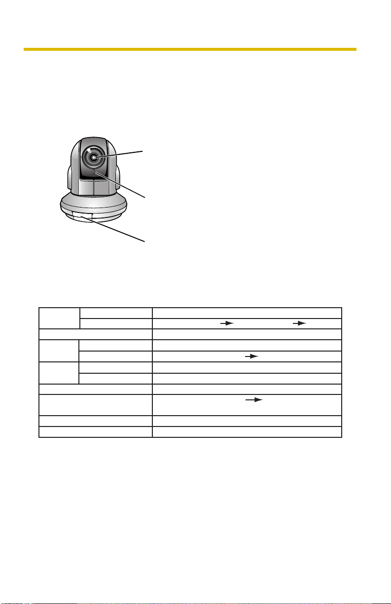
1.1 BB-HCM381A Feature Locations
1.1.1 Front View
Auto Focus/Zoom Lens
Wide: 5 mm (3/16 inches) —Infinity
Tele: 1 m (3 feet 3 inches) —Infinity
Indicator
The indicator color shows camera status (see
page 153).
SD Memory Card Cover
Protects the SD Memory Card from dust. Remove
the cover only when removing the SD Memory
Card (see page 140).
Indicator Display
Powe r
on
Normal Operation*
Automatic
Setup
Using
DHCP
Updating Firmware
FACTORY DEFAULT RESET
*1 The indicator turns orange if the camera is not connected to the LAN.
*2 The indicator blinks orange if the camera is not connected to the LAN.
*3 See page 3 and 4 the Troubleshooting on the CD-ROM for information on indicator error
codes.
Not on LAN
On LAN
1
Setting
Finished setting
Getting IP address*
Got IP address
button pressed
TM
Failure Orange blinking (About a 2-second interval)
UPnP
Internal Failure Red blinking*
Orange blinking Green
2
Orange blinking
Green blinking
Green
Green blinking
Green blinking
Green blinking
Green
Orange blinking
Orange blinking Turning off
(The camera restarts after that.)
Green
3
8
Page 17
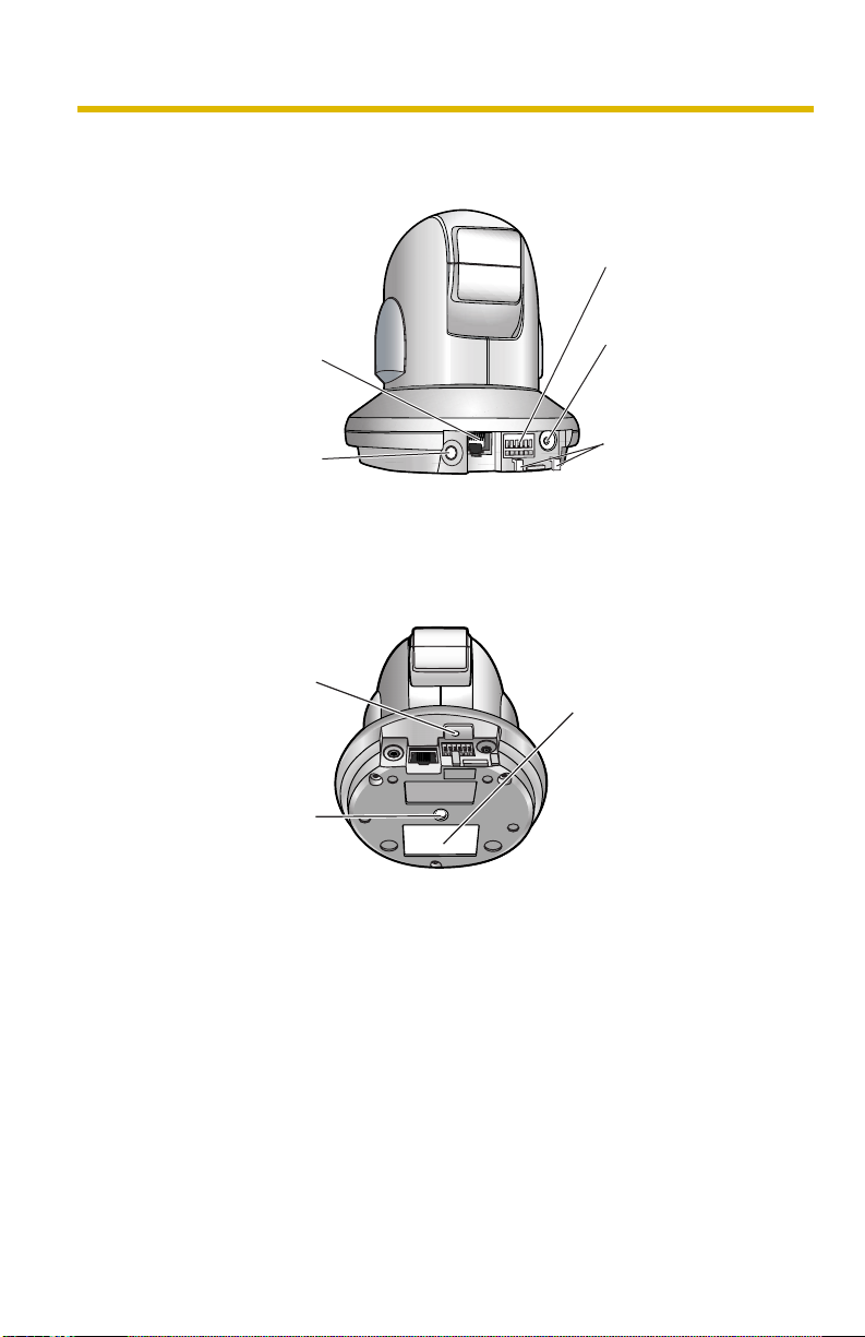
1.1.2 Rear View
Operating Instructions
External I/O
(See page 164)
Ethernet (LAN) port
Connects the camera to
your LAN.
Audio/Video terminal
(See Getting Started)
1.1.3 Bottom View
FACTORY DEFAULT
RESET button
Resets settings to default
(see page 166).
Hole for Ceiling Plate A
Used for ceiling
mounting
(See Installation Guide).
DC IN jack
Connects the camera
to the AC adaptor.
Hook for AC
Adaptor Cord
Used to secure the
AC adaptor cord.
MAC Address and
Serial Number are
indicated on the label.
9
Page 18
Operating Instructions
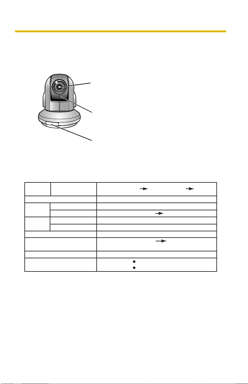
1.2 BB-HCE481A Feature Locations
1.2.1 Front View
Auto Focus/Zoom Lens
Wide: 5 mm (3/16 inches) —Infinity
Tele: 1 m (3 feet 3 inches) —Infinity
Indicator
The indicator color shows camera status (see
page 153).
SD Memory Card Cover
Protects the SD Memory Card from dust. Remove
the cover only when removing the SD Memory
Card (see page 140).
Indicator Display
Powe r
on
Normal Operation
Automatic
Setup
Using
DHCP
Updating Firmware
FACTORY DEFAULT
RESET button pressed
UPnP
Internal Failure
*1 The indicator blinks orange if the camera is not connected to the LAN.
*2 See page 5 and 6 the Troubleshooting on the CD-ROM for information on indicator error
codes.
On LAN
Setting
Finished setting
Getting IP address*
Got IP address
TM
Failure Orange blinking (About a 2-second interval)
Orange blinking Green
Green blinking
1
Orange blinking Turning off
(The camera restarts after that.)
Green blinking
Green
Green blinking
Green blinking
Green
Orange blinking
2
Orange*
Red blinking*
Green
2
10
Page 19
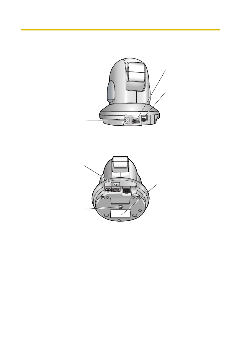
1.2.2 Rear View
Audio/Video terminal
(See Getting Started)
1.2.3 Bottom View
FACTORY DEFAULT
RESET button
Resets settings to default
(see page 166).
Operating Instructions
External I/O
(See page 164)
PoE IN port
Connects the camera
to your PoE hub.
MAC Address and
Serial Number are
indicated on the label.
Hole for Ceiling Plate A
Used for ceiling
mounting.
(See Installation Guide)
11
Page 20

Operating Instructions
1.3 How to Turn on the Camera
Connecting the AC cord (for BB-HCM381A) or the Ethernet cable (for BBHCE481A) turns the camera on, and disconnecting the AC cord (for BBHCM381A) or Ethernet cable (for BB-HCE481A) turns the camera off.
BB-HCM381A
• Connecting the plug of the AC cord to the outlet turns the camera on.
• Disconnecting the plug of the AC cord from the outlet turns the camera off.
BB-HCE481A
• Connecting the Ethernet cable to the Ethernet port on the PoE hub turns the
camera on.
• Disconnecting the Ethernet cable from the Ethernet port on the PoE hub turns
the camera off.
*1
*1
BB-HCE481A does not support the AC adaptor and needs the PoE hub.
12
Page 21

Operating Instructions
1.4 Accessing the Camera
1. Start up the web browser on your PC.
2. Enter "http://IPv4 Address (or URL):Port Number" on the address bar, and
press [Enter] on the keyboard.
• When the port number is 80 (default), you do not need to include the port
number in the address. See page 50 for details about the port number.
• For IPv6 connection, see page 15 and page 16, and confirm that your
equipment meets the requirements.
Enter "http://(IPv6-registered URL):Port Number
• If the camera image is not displayed, see "Camera Image/Page Display
Troubleshooting" on page 9 of the Troubleshooting on the CD-ROM.
E.g. http://192.168.0.253:50000 (in IPv4)
http:// .viewnetcam.com:50000 (in IPv6)
3. The Enter Network Password window is displayed. Enter the user name and
password that you set previously, and click [OK].
Note
• When [Permit access from guest users] is set on the Security:
Administrator page, the authentication window will not be displayed.
" on the address bar.
13
Page 22

Operating Instructions
4. Click the following tabs to display each page.
A B C D E F G
Select a language
Version Number
Displays IPv4, IPv6
or IPsec connection.
A To Single Camera page (page 17) B To Multi-Camera page (page 36)
C To Buffered Image page (page 38) D To Setup page (page 45)
E To Maintenance page (page 154) F To Support page (page 163)
G To log in to the camera (page 92)
Note
• When users other than an administrator are accessing the camera, the [Setup]
and [Maintenance] tabs are not displayed. Additionally, when [Do not permit
access from guest users] or [Permit access from guest users (mobile only)] is
set on the Security: Administrator page, the [Login] tab will not be displayed.
• If [View Multi-Camera page] or [View Buffered Image page] is not permitted on
the General User page, the [Multi-Camera] and [Buffered Image] tabs will not
be displayed.
5. Close the web browser.
14
Page 23

Operating Instructions
1.4.1 To Access the Camera in IPv6
You need to prepare the following to access the camera in IPv6.
• PC Requirements
Operating System: Windows XP Service Pack 1 or later
Web Browser: Internet Explorer 6.0 or later
• An IPv6 Router
• An IPv6 Connection Service
To connect in IPv6, subscribe to the ISP's "IPv4/IPv6 Dual-Stack" or "IPv6 over
IPv4 Tunneling" service. The camera does not function on IPv6-only networks.
IPv6 Domain Name Service
In Windows XP, you cannot access the camera by entering its IP address in the
web browser. Enter the IPv6 URL that was registered using the domain name
service. We recommend the Viewnetcam.com service (see page 70) as a domain
name service. Ask your ISP about other IPv6 domain name services.
What is IPv6?
• IPv6 is short for "Internet Protocol Version 6".
• IPv6 was created to provide the additional IP addresses that will be needed as
the Internet continues to expand.
• IPv6 is expected to gradually replace IPv4, with the 2 coexisting for a number
of years during a transition period.
• Though most ISPs (Internet Service Providers) do not yet support IPv6, many
local networks already use it. When your ISP supports IPv6, your Panasonic
Network Camera will be ready!
• For more information, visit http://www.ipv6.org/.
Setting up the IPv6 Router, your PC, and the Camera
Setting up the IPv6 Router
Set up the router as you subscribe to the IPv6 service. If access from the WAN side
is disabled on the router, enable the TCP packets from the WAN side using packet
filtering. See the Panasonic Network Camera support website at http://
panasonic.co.jp/pcc/products/en/netwkcam/ for information about the
recommended routers.
15
Page 24

Operating Instructions
Setting up your PC
1. Click [Start] [All Programs] [Accessories] [Command Prompt].
• The Command Prompt window is displayed.
2. Enter "ipv6 install".
• "Succeeded" is displayed.
Note
• If Windows XP Service Pack 1 or later is not installed, "Succeeded" will not be
displayed. Install it on your PC.
• When you use Windows XP Service Pack 2, click [Start] [Control
Panel] [Security Center] [Windows Firewall] [Advanced] tab [Settings]
button of ICMP in the Windows Firewall window, then check [Allow incoming
router request] check box in the ICMP Settings window.
3. Enter "ipconfig".
• If the IPv6 address is properly assigned to your PC, IPv6 address will be
displayed in the window.
Setting up the Camera
Usually, an IPv6 address is automatically assigned. To assign a static IPv6
address, see page 53. To access the camera in IPv6, you need to subscribe to a
domain name service such as Viewnetcam.com, and register the URL.
Confirming that You Can Access the Camera
Confirm that the image is properly displayed (see page 13).
16
Page 25
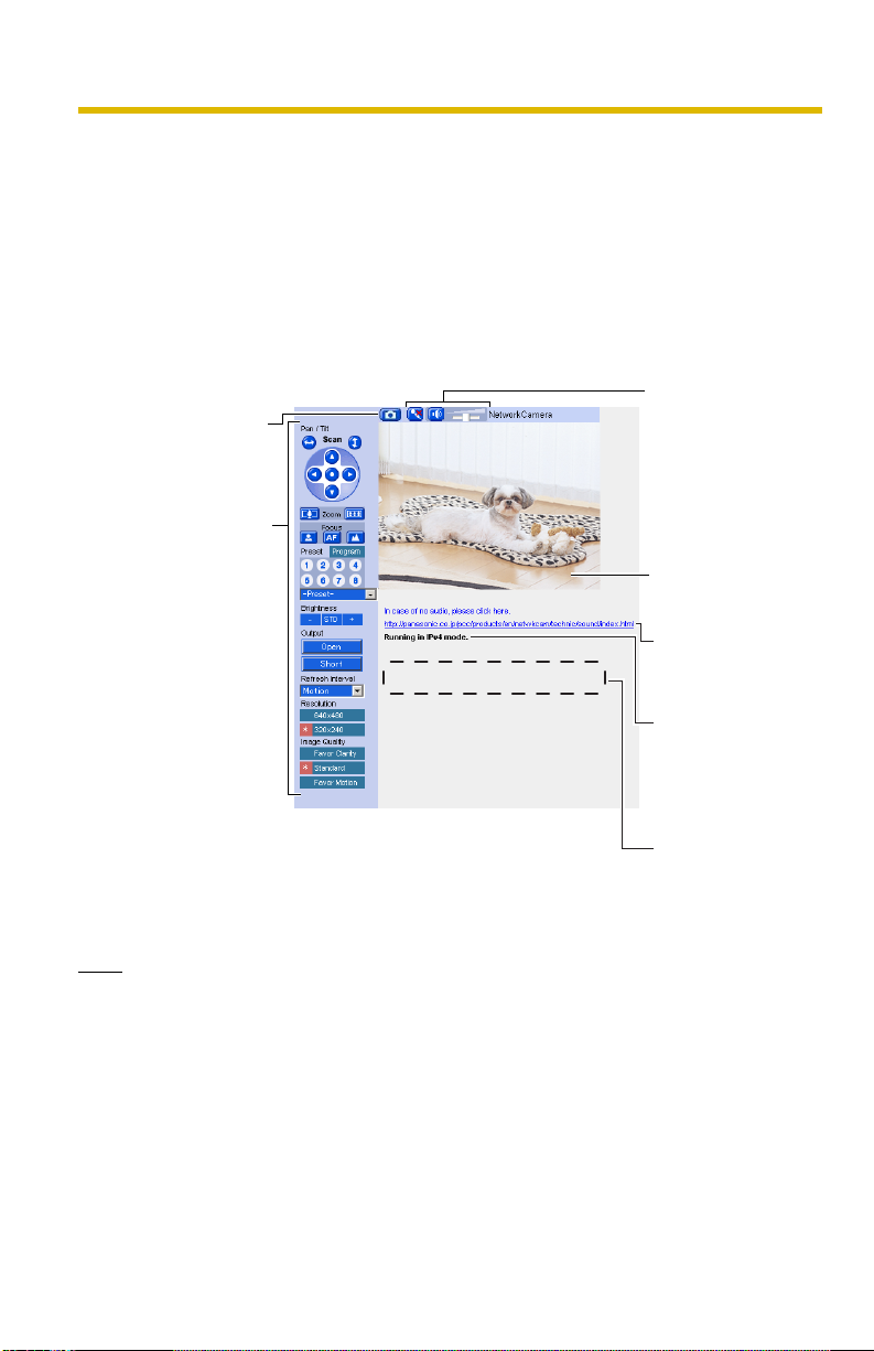
1.5 Viewing the Single Camera page
1. Access the camera (see page 13).
• The Top page is displayed.
2. Click the [Single] tab at the top of the page.
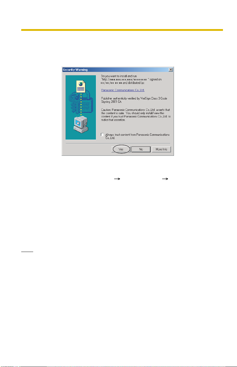
• When the Security Warning window is displayed, click [Yes] (see page 19).
• See page 20 for the Security Warning window when using Microsoft
Windows® XP Service Pack 2.
Capture Image
Button
(See page 22)
Operation Bar
(See page 23)
Operating Instructions
®
Audio Control
Bar (Talk Button,
Listen Button
and Adjustment
Bar)
(See page 34)
Click to Center
(See page 21)
Click the URL in
case of no audio.
Displaying to
operate with
IPv4, IPv6, or
IPsec.
Banner
(optional)
(See page 20)
3. Close the web browser.
Note
• When the camera image is not displayed immediately or correctly, click
[Refresh] on the web browser's tool bar. The image will be refreshed.
• The refresh interval is set to [Motion] by default. The setting can be changed on
the operation bar (see page 23).
• The refresh interval may change depending on the network condition, PC
performance and what object you view. SD memory recording, using IPsec or
enabling Motion Detection will also increase the refresh interval.
17
Page 26

Operating Instructions
• When displaying video (Motion JPEG), the camera allows up to 30
simultaneous accesses. The 31st user trying to access will see a gray screen.
The Buffered Image page is also limited to a maximum of 30 simultaneous
accesses.
• To reduce the data traffic, the video can be automatically changed to refreshing
still images on the General User page (see page 93).
• To display the Single Camera page directly, add it to the [Favorites] on the web
browser.
• To view dark images, enable color night view mode on the Camera Setup page
(see page 80). The image will be brighter, but the refresh interval may increase
and image quality may decrease in a dark place. (See page 80).
• The following error messages can be displayed.
Error Message Cause and Remedy
The operation time has
ended.
The maximum number of
accesses has been
exceeded.
Images cannot be displayed outside the Operation
Time (see page 150).
The camera allows a maximum of 30 simultaneous
accesses when the Refresh Interval is set to [Motion]
and when accessing the Buffered Image page. Users
who try to access the camera when the maximum
number of access has already be reached will see a
gray screen. To view camera images, wait, then click
the Refresh button on your browser. If viewing the
Single Camera page, you can also switch to still
images.
18
Page 27
Operating Instructions
Security Warning window
When trying to view a video (Motion JPEG) for the first time, a Security Warning for
ActiveX
log in as an administrator to install ActiveX Controls and enable video viewing.
If you cannot install ActiveX Controls or you cannot see the video using
the Internet Explorer
• In Internet Explorer, click [Tools] [Internet Options] [Security] tab and click
• ActiveX Controls can be installed from the CD-ROM.
• ActiveX Controls can be downloaded from the Panasonic Network Camera
Note
• When the IP address was changed for the camera, enter it on the address bar.
• Video may not be displayed or audio may not be heard immediately. Wait for a
• If you use a proxy server, set the web browser not to access the proxy server
• In some corporate network environments, a firewall may be used for security
®
Controls will be displayed. When using Windows 2000 or Windows XP,
[Custom level].
(1) Check "Prompt" in "Download signed ActiveX Controls".
(2) Check "Enable" in "Run ActiveX Controls and plug-ins".
(1) Restart the PC.
(2) Confirm that Internet Explorer is closed.
(3) Double-click"ocx\ActiveXInst.exe" on the CD-ROM.
support website at http://panasonic.co.jp/pcc/products/en/netwkcam/.
moment.
(see page 186).
purposes. This may prevent motion video from being displayed. In this situation
we recommend:
– Contacting your network administrator.
– Using regularly refreshed images rather than video.
19
Page 28
Operating Instructions
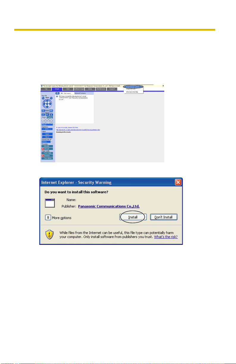
Security Warning window on Microsoft Windows XP Service Pack 2
To view a video (Motion JPEG) or to use audio feature, ActiveX Controls must be
installed.
Follow the steps shown below to install ActiveX Controls.
1. Click the warning displayed above the tabs, and click [Install ActiveX
Control...].
2. Click [Install].
********
1.5.1 Displaying the Banner
An image and its linked website can be specified for a banner. To display the
banner, the Banner Display settings need to be set on the Image Display page (see
page 145). Clicking the banner displays the website of the set URL Link. The
Banner Display is not enabled as the default.
20
Page 29
Operating Instructions
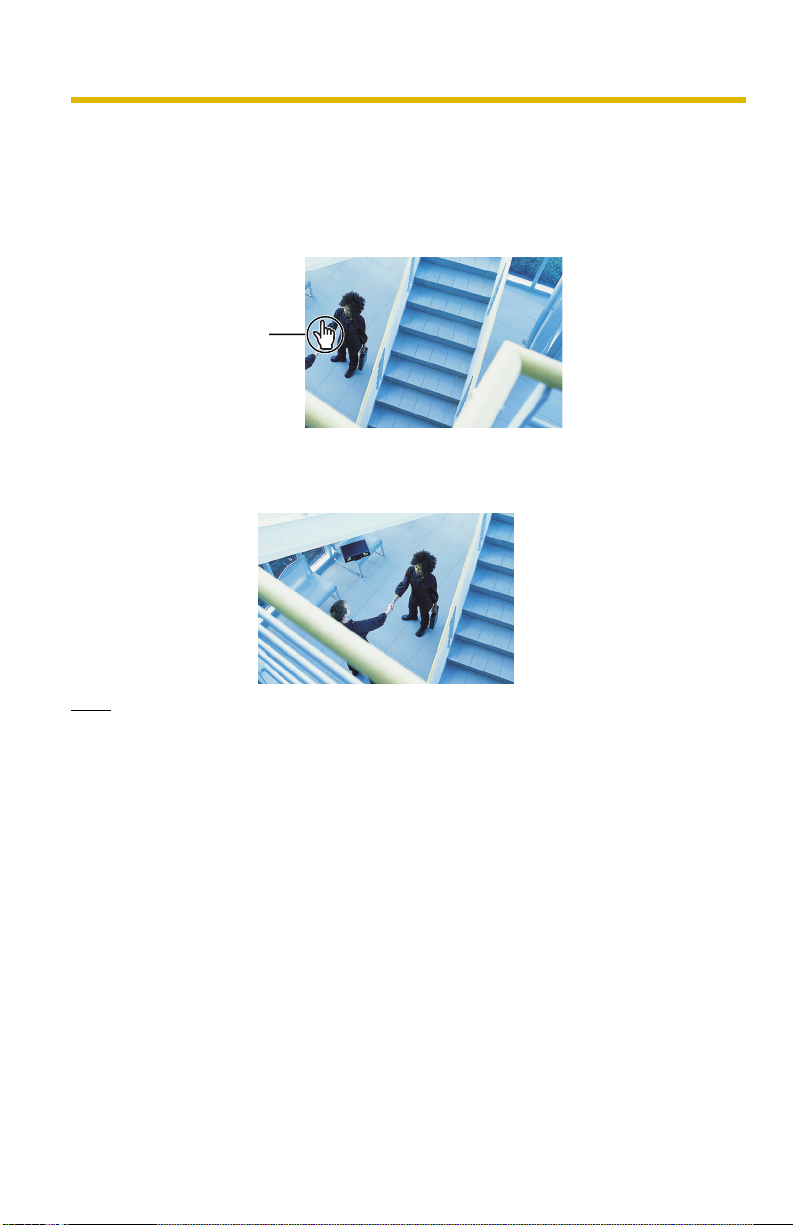
1.5.2 Auto Centering the Image (Click to Center)
Using your mouse, click any portion of the camera image. As long as it is within the
pan/tilt range of the camera, the image will automatically move to place the
selected point in the center of the screen.
1. Move the cursor to the desired point.
Cursor
2. Click it.
• The clicked point is centered.
• See page 25 for the pan/tilt operation.
Note
• When End Display appears on the operation bar, Click to Center does not work
beyond the pan/tilt end (see page 23).
• The camera may not center exactly on the clicked point depending on the lens
direction.
• If Click to Center is not permitted on the General User page (see page 93), the
function will not operate.
21
Page 30
Operating Instructions
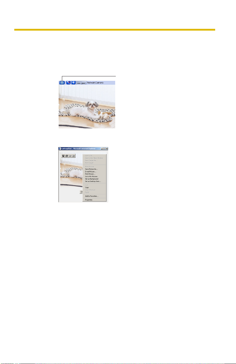
1.5.3 Capturing a Still Image
Still images can be saved on your PC.
1. Operate pan/tilt and select a resolution to display an image.
2. Click the capture image button.
Capture Image Button
• The camera image opens in another window.
3. Right-click the image, and select [Save Picture As...].
• The Save as dialog box is displayed.
4. Specify a folder, enter the file name and click [Save].
• The camera image is saved at that location.
5. Click [Close].
22
Page 31

1.5.4 Using the Operation Bar
Operating Instructions
(1)
(2)
(3)
(4)
(5)
(6)
(1) End Display and Preset Display: When the pan/tilt
has reached the end of its range, the End Display (Left
End, Right End, Up End or Down End) appears. When
the zoom or focus operation has reached the end, Wide
End, Tele End, Near End, or Far End appears. When you
select a preset, the preset name appears.
(2) Pan Scan/Tilt Scan: Moves the lens throughout the
horizontal ( ) or vertical ( ) range, and returns to the
original position.
(3) Pan/Tilt/Home Position: Controls lens direction.
Pan ( : Left, : Right), Tilt ( : Up, : Down) and
Home Position ( : Center [Default])
(4) Zoom Buttons: Zooms in or out on the camera
image.
(5) Focus Buttons: Used to adjust the focus.
(6) Home Position, Alarm Position, Preset Position:
Applies the camera direction to a preset position. You can
preset 20 positions (see page 30—page 33).
When the External I/O detects a signal, the camera can
be set up to turn to the position of Alarm 1 or Alarm 2.
Only an administrator can operate it (see page 30).
23
Page 32

Operating Instructions
(7)
(8)
(9)
(7) Brightness: Adjusts image brightness in 9 steps
including [STD] (Standard). Clicking [-] or [+] changes the
image brightness.
(8) Output Control: Controls the output signals of the
External I/O.
(9) Refresh Interval: Sets a refresh interval. (Motion—
60-second interval)
(10) Resolution: Selects [640 x 480] or [320 x 240]
(default) pixels.
(11) Image Quality: Selects the image quality.
• [Favor Clarity] optimizes the image for good
clarity.
• [Standard] keeps the standard quality. (default)
• [Favor Motion] optimizes the image for motion
display.
24
(10)
(11)
Page 33

Pan/Tilt Operation
The pan scan and tilt scan buttons
automatically move the lens horizontally from
-175° to +175° and vertically from -120° to 0°
in mounting on the table and from 0° to +90°
in mounting on the ceiling, and the lens
returns to the current position. Use Click to
Center feature to stop scanning. Each pan/tilt
arrow moves the lens Up, Down, Right, Left,
and the home position button moves it to
Home Position.
Operating Instructions
Pan Scan/
Tilt Scan
Pan/Tilt
Pan/Tilt range when the camera is
on a table
0˚
Tilt
+175˚
-175˚
Pan
0˚
-120˚
Pan/Tilt range when the camera is
mounted on a ceiling
0˚
+90˚
Tilt
0˚
+175˚
-175˚
Pan
Note
• When the power is on, do not manually pan or tilt the camera. Doing so may
damage the Pan/Tilt operation, or cause the Preset buttons to pan or tilt the
camera to the wrong position. If you accidentally pan or tilt the camera
manually, restart the camera.
25
Page 34

Operating Instructions
1.5.5 Zooming In and Out
Network Camera has a 42x magnifying capacity: the 21x magnifying capacity of
the optical zoom and 2x magnifying capacity of the digital zoom. You can use the
zoom buttons in the Operation Bar or your mouse to zoom in or out on increase or
decrease the size of the object on the Single Camera screen. The zooming feature
has 12 steps (10 steps of Optical Zoom and 2 steps of Digital Zoom).
Using the zoom buttons
Tele button zooms in, and Wide button zooms out.
Wide button
Tele button
Clicking the right mouse button (For Only Video)
Clicking the right mouse button on the upper third of the Single Camera screen
zooms in, and clicking on the lower third zooms out. Zooming in and out is also
available by moving the mouse up or down while pressing the right mouse button.
Zoom in
Zoom out
Rotating the mouse wheel (For Only Video)
On a screen, rotating the mouse wheel away from you zooms in, and rotating it
towards you zooms out.
Zoom in
Zoom out
26
Page 35

Operating Instructions
Note
• Zoom control can be enabled or disabled for General Users and Guest Users
(see page 93). If disabled, a 10x digital zoom is available.
• The performance of the mouse varies according to your OS.
• The optical zoom automatically switches to the digital zoom.
• The definition in the image may decrease when using the digital zoom.
• The position you click may considerably deviate from the center of the image
when using the Click to Center feature on a large zoom scale.
27
Page 36

Operating Instructions
1.5.6 Automatic and Manual Focusing
Focus button adjusts the focus. Network Camera has Automatic and Manual
Focusing features. AF (Automatic Focus) button automatically allows the lens to
focus on objects. Manual focusing starts by pressing Near or Far button. Near
button enables the lens to shorten the focal distance, and Far button lengthens it,
manually. Manual focusing feature has 40 steps.
Near button
Far button
AF (Automatic Focus) button
Note
• Some objects are difficult to focus on by auto focusing. In the objects shown
below, it may take a while to focus on, or may not focus on them. Press the AF
button and put it into operation again. When the objects are still out of focus,
adjust the focus using manual focusing, or change the objects using Pan/Tilt
operation or Zooming features. Manual focusing starts by pressing Near or Far
button. Press AF button for turning it into Automatic Focusing.
The objects that are difficult to focus on by AF button
Objects without contrast
(e.g., White wall)
Light-dotted object in
the dark (e.g., night view)
Horizontally striped
objects
Objects viewed
through glass
High-luminance objects
(e.g., fluorescent lights)
Objects moving fast
• When positioning the camera in front of a window to view images on the other
side of the glass, set the Automatic Focus Range setting to "Normal" (page 80).
• When positioning the camera within 1 m (3 feet 3 inches) of the object you wish
to view, set the Automatic Focus Range setting to "Macro" (page 80).
28
Page 37

Operating Instructions
• Fingerprints, dust, stains, etc. on the lens can degrade the performance of the
Automatic Focusing feature. Wipe the lens with lens cleaning paper.
• The image may be out of focus, if it is too near, or depending on the zoom
position. Move the object, or adjust the zoom position.
• The access level for the zoom feature can be set (see page 93). If the zoom
feature is not permitted, the x10 digital zoom feature is available.
Minimum object distance
During maximum zoom in (Tele) During maximum zoom out (Wide)
5 mm (3/16 inches)1 m (3 feet 3 inches)
29
Page 38

Operating Instructions
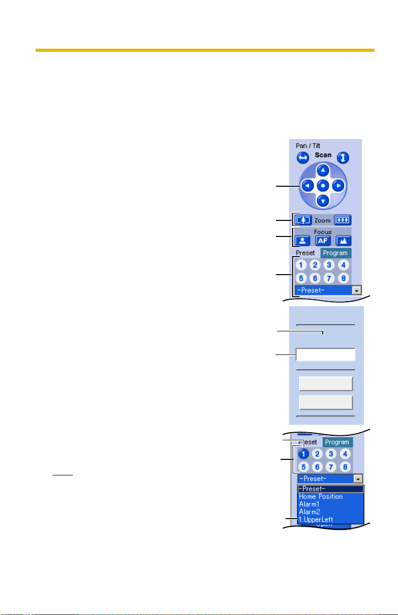
1.5.7 Setting Home Position/Alarm Position/Preset Position
Registering Home Position/Alarm Position
A home position or 2 alarm positions can be registered. When restarted, the
camera takes a home position. If the Lens Position When Triggered setting is set
for buffering images by alarm (see page 107) or by motion detection (see page
119), the camera moves to the alarm position when triggered.
1. Click [Program].
• [Program] switches to [Cancel].
Click [Cancel] to quit without
saving changes.
2. Pan and tilt the camera to a desired
position.
3. Zoom to the desired position.
4. Adjust the focusing if necessary.
5. Select the home position or the
alarm position from the drop-down
list.
6. Click [Save] to register, or click
[Back] and [Cancel] to cancel.
• If "Success!" is displayed, the
position has been registered
successfully. Click [Back].
Home
Position
Pan/Tilt
Zoom
Focus
Program
Home
Position,
Alarm
Position
Drop-down List
30
Page 39
Operating Instructions
Registering a Preset Position
20 camera positions can be stored as presets. These positions can be changed
(see page 33).
• Registered buttons are shown in blue.
• Unregistered buttons are shown in white.
1. Click [Program].
• [Program] switches to [Cancel].
Click [Cancel] to quit without
saving changes.
2. Pan and tilt the camera to a desired
position.
3. Zoom to the desired position.
4. Adjust the focusing if necessary.
Pan/Tilt
Zoom
Focus
5. Select a preset button (1—8) or a
preset position (1—20) from dropdown list, and enter the preset
name.
E.g.:
Setting "UpperLeft" for the preset 1.
When selecting a preset button (1—
8), enter the preset name.
• Maximum 15 characters.
• Enter ASCII characters (see
page 190) or characters in each
language. Note that [Space], ["],
['], [&], [<] and [>] are not
available.
6. Click [Save] to register, or click
[Back] and [Cancel] to cancel.
• If "Success!" is displayed, the
position has been registered
successfully. Click [Back].
Note
• When registering preset positions,
the camera also saves brightness
and white balance settings.
• Only an administrator can register
preset positions.
Preset
Position
Preset
number
Setting
a name
The button
turns blue.
Only buttons
1 to 8 are
displayed.
The preset
number and
preset name
are displayed.
Preset Name
Preset (1) Name
UpperLeft
Save
Back
31
Page 40

Operating Instructions
Viewing the Image
Select the home position, alarm
1.
position or a registered preset
button or position.
• The camera moves to that
position and the image is
displayed.
Home
Position
Pan/Tilt
Placing the
cursor over
the button
displays
the preset
name.
Home Position,
Alarm Position
and Preset
Position
32
Page 41

Changing or Deleting the Settings
Click [Program].
1.
• [Program] switches to [Cancel].
Click [Cancel] to quit without
saving changes.
2. Pan and tilt the camera to a desired
position, or skip to step 5 if deleting
a preset.
3. Zoom to the desired position.
4. Adjust the focusing if necessary.
5. Select the home position, alarm
position or a registered preset
position button (1—8) or (1—20).
Note
• All the items can be selected
from drop-down list. It is also
possible to set positions 1 to 8
as preset buttons.
6. Set the preset name, and click
[Save], or click [Delete].
• To quit the change or deletion,
click [Back], and then [Cancel].
• If "Success!" is displayed, the
position has been registered
successfully. Click [Back].
Note
• The home position and alarm position
cannot be deleted, nor can their
names be changed.
Home
Position
Pan/Tilt
Zoom
Focus
Home
Position,
Alarm
Position
and
Preset
Position
Preset
number
Changing
the name
The deleted
button turns
white.
Only buttons
1 to 8 are
displayed.
The preset
number and
preset name
disappear.
Operating Instructions
Preset Name
Preset (1) Name
UpperLeft
Save
Delete
Back
33
Page 42

Operating Instructions
1.6 Listening to Camera Audio and Talking through the Camera
1. Access the camera (see page 13).
• The Top page is displayed.
2. Click the [Single] tab at the top of the page.
3. The Audio Control Bar (Talk Button, Listen Button and Adjustment Bar) is
displayed at the top of the screen. Listening mode and talking mode are
selected using the relevant icons. This feature is only displayed for general
users when it is enabled.
Audio Feature
Listen Button
Talk Button
: You can talk from the
camera using the PC's
microphone. Clicking the
button stops sending audio.
: The audio is stopped.
Clicking the button again
starts the Talk feature.
: You can listen to the audio
from the camera. Clicking
the button stops the audio.
: The audio is stopped.
Adjustment Bar
(Volume adjustment only for listening)
This slider adjusts the volume. Moving the slider to the
right increases the volume, and moving it to the left
decreases the volume.
34
Page 43

Operating Instructions
Note
• An external microphone and speaker must be connected to the camera (via the
Audio/Video Cable) in order to use the Listen and Talk buttons.
• The Talk button and Listen button cannot be used simultaneously. The Talk
feature is stopped during listening. The Talk feature can be used by only one
user at a time. The Listen feature can be used by a maximum of 10 users
simultaneously. If the audio breaks up, reduce the maximum bandwidth (see
page 48 or page 53). In this case, the number of users who can listen
simultaneously is also reduced.
• Audio features such as camera microphone sensitivity and mute during pan/tilt
can be set up on the Audio page (see page 86).
• If you are running other applications or have multiple windows open, the audio
may be interrupted or delayed.
• When the image is refreshed during any operation such as preset registration
or a web browser refresh, the volume is reset to the default (midrange) position.
Audio that was muted is enabled.
• The audio may be interrupted due to your PC's performance or network
environment. Reduce the maximum bandwidth (see page 48 or page 53).
• If the camera is accessed while the PC user visits other websites, the active
microphone may pick up audio from the PC's speakers. Pay attention to it.
• Talk feature cannot be used from a PC when the camera is accessed via a
proxy server.
• If you cannot hear the audio or talk from your PC, see "Audio Problems
Troubleshooting" on page 17 of the Troubleshooting on the CD-ROM.
• The microphone cable should be no longer than 7 m (23 feet). The excessive
cable length or a poor quality cable can cause a degradation in audio quality.
• Use a speaker with a built-in amplifier. The speaker connects to the camera
with a stereo audio cable similar to that used by your PC. The output signal is
mono.
35
Page 44

Operating Instructions
1.7 Viewing the Multi-Camera page
To view multiple cameras on the Multi-Camera page, you need to configure each
camera on the Multi-Camera Setup page (see page 148).
1. Access the camera (see page 13).
• The Top page is displayed.
2. Click the [Multi] tab at the top of the page.
• The Multi-Camera page can display up to 12 camera images.
Capture Image Button (See page 22)
Switches displayed
cameras. If you select
[All] at the View Type,
video (Motion JPEG) or
audio buttons cannot be
displayed.
Selects [320 x 240]
(default) or [160 x 120]
pixels resolution.
Selects the refresh
interval (Motion—60–
second interval).
The selfcamera is registered
at No. 1.
Audio Control Bar (Talk button, Listen button and Adjustment Bar)
(See page 34)
When clicking the camera
name, the Single Camera
page is displayed on
another window.
3. Close the web browser.
36
Page 45

Operating Instructions
Note
• When selecting [All] for the View Type, all images are displayed in 160 x 120
pixels resolution, and the Audio Control Bar is not displayed.
• 640 x 480-pixel images cannot be displayed on the Multi-Camera page.
• When viewing video (Motion JPEG), we recommend using an Ethernet
switching hub instead of a repeater hub to prevent degradation in video display.
• Due to network congestion or the number of accesses, the refresh interval may
increase.
• If the refresh interval is too long, restrict the bandwidth on the Network page
(see page 51 and page 56). The refresh interval should improve.
• To reduce the data traffic, the video can be automatically changed to refreshing
still images on the General User page (see page 93).
• When viewing 4 cameras on the Multi-Camera page, you may need 3 to 4 Mbps
bandwidth. If sufficient bandwidth is not available, the refresh interval may
increase.
When an image is not displayed on the Multi-Camera page
• Confirm that the global IP address is specified correctly for each camera and
that each camera is connected to the Internet. For Internet access, local IP
addresses (e.g. 192.168.0.253) cannot be used. (see page 11 of
Troubleshooting on the CD-ROM).
• Confirm the settings on the Multi-Camera Setup page (see page 148).
• Confirm that the web browser is not accessing a proxy server (see page 186).
When setting [Do not permit access from guest users] or [Permit
access from guest users (mobile only)] on the Security:
Administrator page
• An authentication window is displayed when accessing the camera. Enter the
administrator's or the general user's user name and password.
• When you view images from several cameras on the Multi-Camera page, an
authentication window is displayed for each camera that has security settings
enabled. Enter the administrator's or general user's user name and password
registered for each camera.
Using the zoom feature on the Multi-Camera page
• The optical zoom is not available when viewing the Multi-Camera page,
however, a 10x digital zoom is available. You can zoom in and out using the
mouse or scroll wheel (see page 26).
• The zoom depth (x1.0—x10.0) is displayed while zooming.
• As the magnification increases, the image quality decreases.
37
Page 46

Operating Instructions
1.8 Viewing the Buffered Image page
To buffer images in the camera's internal memory, you need to set up the image
transfer settings (see page 97, page 107, or page 119). Buffered images can be
viewed on this Buffered Image page.
Note
• Sound cannot be buffered on the Buffered Image page.
1. Access the camera (see page 13).
• The Top page is displayed.
2. Click the [Buffered Image] tab at the top of the page.
3. Click the trigger number.
The trigger number is displayed (see page 97, page 107, or page 119).
The trigger is displayed.
38
Page 47

Operating Instructions
4. Display images by clicking buttons below.
The date and time when the images
were buffered are displayed.
The date, time and frame number
are displayed.
[Play]:
The buffered images are displayed in sequence.
[<Prev] or [Next>]:
The previous or next image is displayed.
[First], [<1000], [<100], [<10] or [10>], [100>], [1000>], [Last]:
The first or last image, or the 10th, 100th or 1000th image before or after the
current image appears.
[Download]
Clicking [Download] after specifying the number of images saves images to the
specified location. The saved files can be viewed in an easier operation on your
PC. Download the viewer software from the Panasonic Network Camera support
website at http://panasonic.co.jp/pcc/products/en/netwkcam/ and install it on
your PC.
Viewer software window
39
Page 48

Operating Instructions
Using the zoom feature on the Buffered Image page
• The optical zoom is not available while playing back buffered images with the
[Play] button, however a 10x digital zoom is available. You can zoom in and out
using the mouse or scroll wheel (see page 26).
• The zoom depth (x1.0—x10.0) is displayed while zooming.
• As the magnification increases, the image quality decreases.
Note
• The buffered images are displayed chronologically.
• Date, time and frame number are not displayed in play mode.
• Still images (not being played) from the Buffered Image page can be saved. Put
the cursor on the image, and right-click it. Then select [Save Picture As...].
• The maximum number of buffered images changes depending on resolution,
image quality and the specific images the camera is buffering. At 320 x 240
pixels resolution and standard quality, the camera can buffer about 125 frames.
(If 3 triggers are enabled [maximum 5 triggers], the internal memory or the SD
memory card capacity is divided into 3 sections. In this case, each trigger can
buffer about 40 frames.) See page 191 for more details regarding the internal
memory capacity. See page 192 for the SD memory card capacity.
1.8.1 Deleting Buffered Images
If you intend to delete images for each transfer method, click [Delete Buffered
Images] on the Trigger page (see page 97, page 107, or page 119).
Note
• If you click [Save] on the Trigger page, all buffered images on the SD memory
card are deleted.
• If you are buffering images to the internal memory, the following operations also
delete all buffered images.
– Turning off or restarting the camera.
– Updating the camera.
– Resetting the camera to default.
– Saving the Date and Time page.
– Changing the Enable/Disable settings on the Image Buffer/Transfer page
(see page 97, page 107, or page 119).
40
Page 49

Operating Instructions
1.9 Viewing Still Images on Your Cell Phone
Still images can be viewed over the Internet from a compatible cell phone.
Enter "http://IP address (or URL):Port Number/Mobile" on a cell phone and
press [OK].
• When the port number is set to 80 (default), it is not required.
E.g.
http:// . . . :50000/Mobile
(or .viewnetcam.com:50000/Mobile)
• Access to the camera from cell phones must be allowed.
• When an authentication window is displayed, enter the administrator's or
general user's user name and password.
• A still image is displayed. (Video [Motion JPEG] cannot be displayed.)
41
Page 50

Operating Instructions
(1)
(2)
(3)
(4)
(5)
(1) Pressing 2, 4, 6 or 8 on the cell
phones allows you to pan or tilt the
camera in four directions: Left, Up, Down
or Right.
(2) Pressing allows you to zoom in, and
pressing # allows you to zoom out.
(3) Pressing 5 will refresh the image.
(4) 160 x 120 resolution is displayed on
the first access. Pressing 0 switches the
resolution to 320 x 240.
(6)
(7)
(8)
(9)
(5) Executing [Home Position] moves the
lens to the home position.
(6) Pressing 1, 3, 7 or 9 on the keypad
allows you to use the first four registered
preset buttons.
(7) Registered presets 5—20 are
available by activating the link on the cell
phone page.
(8) Displays up to 50 Logs in order of
time, when logging in as an administrator
(see page 43).
(9) Allows you to use your cell phone to
enable/disable the image buffer/transfer
feature (see page 44).
42
Page 51

Operating Instructions
(10) Goes to the control page.
(11) Displays the number of new logs.
(12) Displays the date and time, the kind
of signal and sensor.
(10)
(10)
Display
(11)
(12)
(13)
A1 R
A2 F
MD
Operation
Alarm1
Alarm2
Motion
Detection
Signal
Rising:
GND to Open (High)
Falling:
Open (High) to GND
-
(13) Goes to the control page.
Note
• Audio feature does not work on cell phones.
• If the features are not permitted on the General User page (see page 93), the
buttons related with the features are not displayed.
• If the image is not displayed properly, try the following 2 URLs.
1. http:// IP address(or URL):Port Number/MobileH
for HTML.
(or .viewnetcam.com:50000/MobileH)
2. http:// IP address(or URL):Port Number/MobileX for XHTML.
(or .viewnetcam.com:50000/MobileX)
• When pan, tilt, or zoom reaches the end, the keypad number and character disappear.
E.g.: The pan reaches the left end.
(4)L(2) U (8) D (6)R
#
( )Tele (
)Wide
"(4)L" disappears.
(2)U(8) D (6) R
#
( )Tele (
)Wide
• Some cell phones are not compatible with Panasonic Network Cameras. Some
phones may allow viewing only on port 80, and some may not support
password authentication. See the Panasonic Network Camera support website
at http://panasonic.co.jp/pcc/products/en/netwkcam/ for a list of cell
phones, and their level of compatibility with the Panasonic Network Camera.
• Some cell phones display images at a decreased size.
• If [Permit access from guest users] or [Permit access from guest users (mobile
only)] is selected, users can access cell phone-specific screens via a cell
phone or PC without the need for authentication.
• Only administrators can operate the Alarm Log and Buffer/Transfer.
43
Page 52

Operating Instructions
1.9.1 Enabling or Disabling the Buffer/Transfer on your Cell Phone
1. Access camera images from your cell phone, and log in as an administrator.
2. Select [Buffer/Transfer].
3. Select a trigger number that you want to enable or disable.
Example: Enabling the Buffer/Transfer setting (No.1).
• Selecting [Control Page] changes to the previous page.
4. Select [Save].
44
• Selecting [Save] enables or disables the buffer/transfer settings, and all
buffered images will be deleted.
• Selecting [Cancel] takes you back to the previous page without saving
changes.
Page 53

Operating Instructions
2 Using the Camera's Basic Features
2.1 Setup Page of the Camera
1. Access the camera (see page 13).
• The Top page is displayed.
Note
• When [Permit access from guest users] is set on the Security:
Administrator page, click the [Login] tab and log in as an administrator.
• When users other than an administrator are accessing the camera, the
[Setup] and [Maintenance] tabs are not displayed.
• If [View Multi-Camera page] or [View Buffered Image page] is not
permitted on the General User page, the [Multi-Camera] or [Buffered
Image] tab will not be displayed.
2. Click the [Setup] tab at the top of the page.
(1)
—
—
(2)
—
(3)
—
(4)
—
(5)
—
(6)
—
(7)
—
(8)
(9)
—
–
(10)
(11)
(12)
(13)
(14)
(15)
(16)
(17)
(18)
–
–
–
–
–
–
–
–
45
Page 54

Operating Instructions
Basic
(1) Network (IPv4) Configures the IPv4 network settings to connect the
camera to the network (see page 48).
(2) Network (IPv6) Configures the IPv6 network settings to connect the
camera to the network (see page 53).
(3) IPsec Enables IPsec (Transport or Tunnel mode) (see page
57).
(4) UPnP Enables automatic port forwarding and creates a
shortcut to the camera (see page 67).
(5) DynamicDNS Registers with a DNS service, such as Viewnetcam.com
service (see page 70).
(6) Date and Time Sets the date and time, automatic time adjustment and
daylight saving time settings (see page 77).
(7) Camera Sets camera name, white balance, AC power source
frequency, automatic focus range, mounting type, pan/
tilt range, return to specified position, color night view,
and vertical resolution settings (see page 80).
(8) Audio Sets output, volume, PC audio input timeout, input,
camera microphone sensitivity and mute during pan/tilt
settings (see page 86).
Account
(9) Administrator
*1
(10)
General User
Sets authentication and administrator security (user
name and password) (see page 88).
*1
Sets general user security (user name and password)
and access levels (see page 93).
Buffer/Transfer
(11) Trigger Sets image buffer or transfer by timer, alarm, or motion
detection (see page 97, page 107, or page 119).
(12) Motion
Detection
Sets the threshold and sensitivity for motion detection
(see page 133).
(13) Alarm Log Sets the information required to send log notifications by
e-mail (see page 137).
Advanced
(14) Image Display Sets the resolution, image quality and refresh interval of
the Single Camera and Multi-Camera page, as well as
time stamp setting, language and banner (see page
145).
46
Page 55

Operating Instructions
(15)
Multi-Camera
*1
Sets the camera IP address or host name, and camera
name on the Multi-Camera page (maximum 12
cameras) (see page 148).
(16) Operation
Time
(17) External
Output
(18) Indicator
Sets the time period to display camera images (see
page 150).
Sets the external output terminal of the External I/O (see
page 152).
Sets the indicator display (see page 153).
Control
*1 If you change the [Administrator], [General User], or [Multi-Camera Setup page] settings,
changes will not be applied to video (Motion JPEG) viewers. Restart the camera to apply
changes to all video viewers.
47
Page 56

Operating Instructions
2.2 Connecting the Camera to Your IPv4 Network
The Network page offers three options to configure the camera in IPv4.
• [Automatic Setup] automatically assigns an unused IP address to the camera,
and uses UPnP™ (Universal Plug and Play) to configure your router.
• [Static] allows the user to use a specific IP address.
• [DHCP] is offered for ISPs that require this option.
1. Click [Network (IPv4)] on the Setup page.
2. Click a connection mode.
Most common mode of setup.
Uses a static IP address.
Uses ISP DHCP server function.
• See below for details of each connection mode.
3. Enter each parameter in the relevant data field.
Automatic Setup
The camera automatically obtains the network settings (subnet mask, default
gateway and DNS server address) using the router's or ISP's DHCP feature.
The camera also automatically searches for an unused IP address on your
network. If you select [Yes] for Allow Access from the Internet, the camera
automatically enables port forwarding using UPnP™. In this case, the camera
automatically searches for an unused port number on your network in order
of 80 and from 50000 to 50050.
48
• Clicking [Cancel] takes you back to the previous page without saving
changes.
Page 57

DHCP Setup Static Setup
• Clicking [Cancel] takes you back to the previous page without
saving changes.
4. Click [Save] when finished.
• The new settings are saved.
• When finished, the following page is displayed.
Operating Instructions
Note
• The current network settings are shown on the Status page in the
Maintenance section (see page 155).
5. Click [Restart].
• The camera restarts, and the Top page is displayed.
• Checking [Yes] for [Allow Access from the Internet] on [Automatic Setup]
may not display the Top page, because the port number may change. Use
the Setup Program to access the camera.
Note
• If you do not know the camera IP address when setting [Automatic Setup]
or [DHCP Setup], it can be searched for by the Setup Program (see page
180).
49
Page 58

Operating Instructions
• When the camera is restarted, all buffered images in the internal memory
are deleted. The buffered images on the SD memory card are not deleted.
Setting Description
Allow Access from
the Internet
(Automatic Setup
Only)
Network
Configuration from
Setup Program
(Static/DHCP Only)
Por t Numbe r
(Static/DHCP Only)
• IP address
• Subnet Mask
(Static Only)
• The allow Access from the Internet setting
automatically configures the router's Port Forwarding
setting (some routers call it "Address Translation",
"Static IP Masquerade", "Virtual Server" or "Port
Mapping"). To enable Internet access to the camera,
check [Yes]. In this case, the camera automatically
searches for unused port number on your network in
order of 80 and from 50000 to 50050. To disable
Internet access to the camera, check [No].
• To prohibit the Setup Program from changing the
network settings, uncheck the box.
• The default port number is 80. When you use multiple
cameras with a router on your network, each camera
must be assigned its own port number (see page 68
"2.7.2 Connecting the Camera to a Router that Does
™
Not Support UPnP
(IPv4 Only)").
– Do not set the following port numbers.
FTP: 20 and 21, Telnet: 23, SMTP: 25, DNS: 53,
POP3: 110, HTTPS: 443, ICQ: 4000 and IRC:
6661—6667.
• Enter a number between 1—65535.
• Some ISPs do not allow you to use port 80. Ask your
ISP or network administrator about which port
numbers are accessible over the Internet.
• If your ISP or network administrator specifies an IP
address and subnet mask, enter them in each data
field.
• If you use the camera on a LAN, set an IP address with
the same class as your PC (see page 179).
• Set 4 numbers (0—255) and 3 periods, such as
"192.168.0.253". Note that "0.0.0.0" and
"255.255.255.255" are not available.
50
Page 59

Setting Description
Host Name
(DHCP Only)
• If your ISP uses the DHCP function, which
automatically assigns an IP address to the camera,
enter the ISP–assigned host name. (The host name
may be used as an authentication.)
• Enter ASCII characters for the host name (see page
190). Note that [Space], ["], ['], [&], [<] and [>] are not
available.
*1
Default Gateway
(Static/DHCP Only)
• If you have been assigned a Default Gateway address
by your ISP or network administrator, enter it in this
data field.
• Set 4 numbers (0—255) and 3 periods, such as
"192.168.0.253". Note that "0.0.0.0" and
"255.255.255.255" are not available.
DNS Server
Address
*1
(Static/DHCP Only)
• The DNS server address is required in the following
situations:
– Transferring camera images by E–mail or FTP
– Setting cameras by their host names on the
Multi-Camera Setup page
– Using the DynamicDNS service
– Using the alarm log notification
• If you have been assigned a DNS server addresses by
your ISP or network administrator, enter them in this
data field. There are usually two addresses.
• Set 4 numbers (0—255) and 3 periods, such as
"192.168.0.253". Note that "0.0.0.0" and
"255.255.255.255" are not available.
Max. Bandwidth
Usage
• The bandwidth can be restricted.
• Select a maximum bandwidth from [Unlimited] to [0.1
Mbps].
• This setting is valid in both IPv4 and IPv6.
Note
• Set a maximum bandwidth referring to the following file
sizes. These are examples for a JPEG file of standard
image quality. File sizes may change depending on the
image quality or the brightness of the object.
– 160 x 120 pixels: About 3.5 KB (28 Kbit)
– 320 x 240 pixels: About 10 KB (80 Kbit)
– 640 x 480 pixels: About 18 KB (144 Kbit)
Operating Instructions
51
Page 60

Operating Instructions
Setting Description
Connection Type • Select [Auto Negotiation] normally. If the camera
cannot be accessed, see page 9 of the
Troubleshooting on the CD-ROM.
• This setting is valid in both IPv4 and IPv6.
*1 If the IP address is automatically obtained from a DHCP server, this field does not need
to be set.
52
Page 61

Operating Instructions
2.3 Connecting the Camera to Your IPv6 Network
The Network page offers two options to configure the camera in IPv6.
• [Automatic Setup] automatically assigns an IPv6 address to the camera.
• [Static] allows the user to use a specific IPv6 address.
Note
• IPv6 is an expanded protocol created for future Internet expansion. Your
network and your ISP must support IPv6 before you can use this feature.
1. Click [Network (IPv6)] on the Setup page.
2. Click a connection mode.
Most common mode of setup.
Uses a static IP address.
3. Enter each parameter in the relevant data field.
Automatic Setup
The camera is automatically assigned an IPv6 prefix from the IPv6 router, and
produces the original IPv6 address from the IPv6 prefix. If you select [No] for
Allow Access from the Internet, the camera can be accessed only from the
LAN that has an same IPv6 prefix as the camera.
• Clicking [Cancel] takes you back to the previous page without saving
changes.
53
Page 62

Operating Instructions
Static Setup
You can assign a static IPv6 address to the camera. If you select [No] for Allow
Access from the Internet, the camera can be accessed only from the LAN that
has an same IPv6 prefix as the camera.
• Clicking [Cancel] takes you back to the previous page without saving
changes.
4. Click [Save] when finished.
• The new settings are saved.
• When finished, the following page is displayed.
Note
• The current network settings are shown on the Status page in the
Maintenance section (see page 155).
5. Click [Restart].
• The camera restarts, and the Top page is displayed.
Note
• When you do not know the camera IP address while setting [Automatic
Setup], you can search for it using the Setup Program (see page 180). Or
you can search for it on the Status page (see page 155) after accessing
the camera in IPv4.
• If the camera is restarted, all buffered images on the internal memory are
deleted. The buffered images on the SD memory card are not deleted.
54
Page 63

Setting Description
Allow Access from
the Internet
• If [Yes] is selected for Allow Access from the Internet,
you can access the camera from the Internet. If [No] is
selected, the camera can be accessed only from a LAN
that has an same IPv6 prefix as the camera.
Port Number (Static
Only)
• The default port number is 80. A unique port number
must be set for each terminal on your network.
• Do not set the following port numbers.
FTP: 20 and 21, Telnet: 23, SMTP: 25, DNS: 53,
POP3: 110, HTTPS: 443, ICQ: 4000 and IRC: 6661—
6667.
• Enter a number between 1—65535.
• Some ISPs do not allow you to use port 80. Ask your
ISP or network administrator about which port
numbers are accessible over the Internet.
IP address
(Static Only)
• Enter a global address. You do not need to enter a
prefix length.
• An IPv6 address consists of 8 hexadecimal numbers
divided by ":". Consecutive 0s can be abbreviated as
"::". (E.g. 2001:2:3:4::5)
Default Gateway
(Static Only)
• If you have been assigned a Default Gateway IPv6
address by your ISP or network administrator, enter it
in this data field.
• An IPv6 address consists of 8 hexadecimal numbers
divided by ":". Consecutive 0s can be abbreviated as
"::". (E.g. 2001:2:3:4::5)
DNS Server
Address
• The DNS server address is required in the following
situations:
– Transferring camera images by E–mail or FTP
– Setting cameras by their host names on the
Multi-Camera Setup page
– Using the DynamicDNS service
– Using the alarm log notification
• If you have been assigned a DNS server IPv6
addresses by your ISP or network administrator, enter
them in this data field. There are usually two
addresses.
• An IPv6 address consists of 8 hexadecimal numbers
divided by ":". Consecutive 0s can be abbreviated as
"::".
(E.g. 2001:2:3:4::5)
Operating Instructions
55
Page 64

Operating Instructions
Setting Description
Max. Bandwidth
Usage
• The bandwidth can be restricted.
• Select a maximum bandwidth from [Unlimited] to [0.1
Mbps].
• This setting is valid in both IPv4 and IPv6.
Note
• Set a maximum bandwidth referring to the following file
sizes. These are examples for a JPEG file of standard
image quality. File sizes may change depending on the
image quality or the brightness of the object.
– 160 x 120 pixels: About 3.5 KB (28 Kbit)
– 320 x 240 pixels: About 10 KB (80 Kbit)
– 640 x 480 pixels: About 18 KB (144 Kbit)
Connection Type • Select [Auto Negotiation] normally. If you cannot
access the camera, see page 9 of the Troubleshooting
on the CD-ROM.
• This setting is valid in both IPv4 and IPv6.
56
Page 65

Operating Instructions
2.4 What is IPsec?
IPsec provides security for the transmission of sensitive information over
unprotected networks such as the Internet. IPsec authenticates IP packets
between participating IPsec devices.
Unreadable
Image
Allowed User
Readable
Malicious User
Internet
Camera's IPsec Features
The camera can use IPsec in both IPv4 and IPv6. The camera supports the
following IPsec features.
Item Supported Feature
IKEv1 Pre-shared Key Method
*1
*2
IPsec
Phase 1 mode :
Main mode
Phase 2 mode : Quick mode
Cipher Algorithm : DES-CBC, 3DES-CBC, AES-CBC (128, 192,
256 bits)
Message-Digest
: HMAC-MD5, HMAC-SHA-1
Algorithm
ESP (Encapsulating Security Payload)
Transport mode, Tunnel mode
Cipher Algorithm : DES-CBC, 3DES-CBC, AES-CBC (128, 192,
256 bits)
Message-Digest
: HMAC-MD5-96, HMAC-SHA-1-96
Algorithm
*1 The camera does not support aggressive mode.
*2 The camera does not support authentication header (AH).
57
Page 66

Operating Instructions
IPsec Mode Selection
Select transport mode or tunnel mode to access the camera.
Transport Mode (IPv4 Only)
The image is encrypted for the whole way between the camera and your PC. The
transport mode is available only in IPv4 for users of Windows XP Service Pack 1
or later.
Transport Mode
Encrypted
Prepare the following required items:
Item Supported Feature
PC Operating
System
Web Browser : Internet Explorer 6.0 or later
ISP Service : A service for multiple global addresses (A
Note
• To use IPsec, you need to set up your operating system. See
the Panasonic Network Camera support website at http://
panasonic.co.jp/pcc/products/en/netwkcam/ for setup
details.
Camera ISP Service : A service for multiple global addresses (A
: Windows XP Service Pack 1 or later
global address must be set up on your PC.)
global address must be set up to the camera.)
58
Page 67

Operating Instructions
Tunnel Mode (IPv4/IPv6)
An IPsec mode of operation where the entire IP packet including IP header is
authenticated and encrypted. A new IP header is added (protecting the entire
original packet). Both VPN clients and VPN gateways can use this mode.
Note
• The camera can be accessed only from PCs under the VPN router. Other PCs
cannot access the camera.
LAN
WAN
Tunnel Mode
Not Encrypted
Encrypted
Prepare the following required items:
Item Supported Feature
PC Operating
System
: Windows XP, Windows 2000, Windows Me,
Windows 98SE (in IPv4)
: Windows XP Service Pack 1 or later (in IPv6)
Web Browser : Internet Explorer 6.0 or later
Router ISP Service
(in IPv4)
: A service for static global addresses (A global
address must be set up to the WAN side of the
router.)
ISP Service
(in IPv6)
: An "IPv4/IPv6 Dual-Stack" or "IPv6 over IPv4
Tunneling" service
Note
• See the Panasonic Network Camera support website at http:/
/panasonic.co.jp/pcc/products/en/netwkcam/ for the
recommended router.
Camera ISP Service
(in IPv4)
ISP Service
(in IPv6)
: A service for multiple global addresses (A
global address must be set up to the camera.)
: An "IPv4/IPv6 Dual-Stack" or "IPv6 over IPv4
Tunneling" service
59
Page 68

Operating Instructions
2.5 Encrypting the Camera Image in Transport Mode
The camera can encrypt images using IPsec transport mode.
Note
• If you use IPsec, the refresh interval increases.
1. Click [IPsec] on the Setup page.
2. Click Camera in the Transport column.
• If you use transport mode for E-mail or FTP transfer, click No. in the Buffer/
Tr a n s fe r c ol um n.
The display shows
that the
communication is
Set to use
Alarm Log.
(See page
137)
Set up these settings to transfer images in transport mode (see page 131).
in HTTP and
anyone can
access the
camera if they
have the preshared key.
Note
• To display an Alarm Log, set Alarm 1, Alarm 2 or Motion Detection for the
Trigger Setting and check [Enable].
3. Enter each parameter in the relevant data field.
60
Page 69

Operating Instructions
Setting Description
Status • Check the box to use this encryption method.
Pre-Shared Key • This is the key used in the authentication of
communications. Enter the same pre-shared key as
your PC.
• Enter ASCII characters for the host name (see page
190). But [Space], ["], ['], [&], [<] and [>] are not
available.
Note
• If the pre-shared key becomes known to a third party, it
may lead to illegal access, a leak of private information
or interference. To protect your security and privacy,
pay attention to the following points.
– Make it known only to people you trust.
– Set it as long and complex as possible.
– Change it regularly.
4. Click [Save] when finished.
• The new settings are saved.
5. Click [Cancel].
• The IPsec page is displayed.
6. Check [Use] in the IPsec column, select an encoding strength, and click
[Save].
Setting Description
IPsec • Check the box to enable IPsec features. If you uncheck
the box, all IPsec features will be invalid.
Encoding strength • The encoding strength for IPsec can be selected. If you
select [Standard], DES or NULL is valid as an
algorithm, and the data will become easier to decrypt.
61
Page 70

Operating Instructions
7. Click [Restart].
8. Set up your PC according to the requirements on page 58.
• Set the FTP server or E-mail server to transfer images.
9. Access the camera (see page 13).
• If you can access the camera, the IPsec setup is complete.
Note
• In IPsec communications, "IPsec" is displayed on the Top page or the
Single Camera page.
• If you cannot communicate using IPsec, see page 24 of Troubleshooting
on the CD-ROM.
• See the Panasonic Network Camera support website at
http://panasonic.co.jp/pcc/products/en/netwkcam/ for IPsec features.
62
Page 71

Operating Instructions
2.6 Encrypting the Camera Image in Tunnel Mode
The camera can encrypt images using IPsec tunnel mode.
Note
• Do not set IPsec on PCs under the VPN router. Communications may be
blocked.
• If you use IPsec, the refresh interval increases.
• The camera can be accessed only from PCs under the VPN router. Other
PCs cannot access the camera.
1. Click [IPsec] on the Setup page.
2. Click Add in the Tunnel column.
3. Enter each parameter in the relevant data field.
Setting Description
Status • Check the box to use this encryption method.
63
Page 72

Operating Instructions
Setting Description
Pre-Shared Key • This is the key used in the authentication of
communications. Enter the same pre-shared key as
your VPN router.
• Enter ASCII characters for the host name (see page
190). But [Space], ["], ['], [&], [<] and [>] are not
available.
Note
• If the pre-shared key becomes known to a third party, it
may lead to illegal access, a leak of private information
or interference. To protect your security and privacy,
pay attention to the following points.
– Make it known only to people you trust.
– Set it as long and complex as possible.
– Change it regularly.
Network address • Enter the destination network address.
• Enter "IP address/Prefix length" in the data field.
Router address • Enter the WAN IP address of the destination network
VPN router.
Note
• An IPv6 link-local address is not available.
• The camera can be accessed only from PCs under
the VPN router. Other PCs cannot access the
camera.
4. Click [Save] when finished.
• The new settings are saved.
5. Click [Cancel].
• The IPsec page is displayed.
6. Check [Use] in the IPsec column, uncheck the encoding strength, and click
[Save].
64
Page 73

Operating Instructions
Setting Description
IPsec • Check the box to enable IPsec features. If you uncheck
the box, all IPsec features will be invalid.
Encoding strength • The encoding strength for IPsec can be selected. If you
select [Standard], DES or NULL is valid as an
algorithm, and the data will become easier to decrypt.
7. Click [Restart].
8. Set up your VPN router as shown below.
• To use tunnel mode, you need to set up your VPN router.
IKE Items Settings
Phase 1 Authentication
Method
ID Specifies by address.
Mode
Diffie-Hellman
MODP Group
Cipher Algorithm Select from DES-CBC, 3DES-CBC or
Message-Digest
Algorithm
Lifetime Specifies by 28800 s (Byte setting is
Phase 2 Mode Quick mode
PFS Specifies either of Off, D-H Group 1
Cipher Algorithm Select from DES-CBC, 3DES-CBC,
Message-Digest
Algorithm
Lifetime Specifies by 28800 s (Byte setting is
Pre-shared Key Method
Main mode
*1
Specifies 1 or 2.
AES-CBC (128, 192, 256 bits).
(Multiple selections are available.)
HMAC-MD5, HMAC-SHA-1
not supported.)
or D-H Group 2.
AES-CBC (128, 192, 256 bits) or
NULL. (Multiple selections are
available.)
HMAC-MD5-96, HMAC-SHA-1-96
not supported.)
*1 The camera does not support aggressive mode.
65
Page 74

Operating Instructions
• Set up the IPsec policy as below.
Items Settings
Protocol ANY
Source Network Network address and subnet mask on the LAN side of
the VPN router
Source IP address A global address on the WAN side of the VPN router
Destination Network A global address of the camera
Destination IP address A global address of the camera
9. Access the camera (see page 13).
• If you can access the camera, the IPsec setup is complete.
Note
• In IPsec communications, "IPsec" is displayed on the Top page or the
Single Camera page.
• If you cannot communicate using IPsec, see page 24 of the
Troubleshooting on the CD-ROM.
• See the Panasonic Network Camera support website at
http://panasonic.co.jp/pcc/products/en/netwkcam/ for IPsec features.
66
Page 75

Operating Instructions
2.7 Using UPnP™ (Universal Plug and Play)
UPnP™ can automatically configure your router to make it accessible from the
Internet. In order to use this feature, your router needs to support UPnP™, and it
must be enabled. UPnP™ is disabled on most routers by default. Most router
manufacturers disable this feature as the default setting. See http://
panasonic.co.jp/pcc/products/en/netwkcam/ and your router's manual for
details of how to enable UPnP™. After UPnP™ is enabled on the router, set
[Enable] for auto port forwarding.
Note
• The camera’s UPnP™ does not support IPv6. Use this feature in IPv4.
1. Click [UPnP] on the Setup page.
2. Set up UPnP™.
Setting Description
Auto Port
Forwarding
Display Shortcut
Icon in My Network
Places
• If the network setting is [Status] or [DHCP], enabling
auto port forwarding allows you to access the camera
from the Internet.
Note
• If the network setting is [Automatic Setup], also enable
[Allow Access from the Internet] on the Network page
(see page 50).
• Enabling this creates a shortcut to the camera in the
My Network Places folder.
Note
• To enable this feature when using Windows XP or
Windows Me, enable the UPnP™ Windows component
beforehand (see page 189).
3. Click [Save] when finished.
• The new settings are saved.
• When finished, "Success!" is displayed.
67
Page 76

Operating Instructions
4. Click [Go to UPnP page].
• The UPnP page is displayed.
2.7.1 Connecting the Camera to a Router that Supports UPnP™ (IPv4 Only)
To allow access from the Internet with a router supporting UPnP™, follow the
procedures shown in Getting Started.
Note
• On some routers, the UPnP™ feature is disabled by default. Enable your
router's UPnP
camera. See the Panasonic Network Camera support website at http://
panasonic.co.jp/pcc/products/en/netwkcam/ for details.
• If a maximum idle time is set in PPPoE or PPTP connection with your ISP,
disable it on the router. See the router manual for details.
™
feature following the router manual before you set up the
2.7.2 Connecting the Camera to a Router that Does Not Support UPnP™ (IPv4 Only)
To allow access from the Internet with a router that does not support UPnP™, follow
the procedures below.
1. Select [Static] on the Network (IPv4) page.
(1) Access the camera (see page 13).
(2) Click the [Setup] tab at the top of the page.
(3) Select [Static] on the Network page.
• The Static IP Address Configuration page is displayed. Make a
note of the IP address and port number, since they are required to
enable port forwarding on the router.
Note
• You must assign a unique IP address and a unique port number
to each camera on the LAN.
(4) Click [Save] without changing the settings.
(5) Click [Restart].
2. Enable port forwarding*
Using the IP address and port number noted on step 1-(3), enable port
forwarding on the router. See the router manual for how to enable port
forwarding.
1
on the router.
3. Register with the Viewnetcam.com service.
68
Page 77

Operating Instructions
Port Forwarding feature*1 (IPv4 Only)
The port forwarding feature is required to allow camera access from the Internet
with a router that does not support UPnP™. It exchanges a local IP address for a
global one.
Global IP address
of the router
vvv.xxx.yyy.zzz:80
vvv.xxx.yyy.zzz:81
Internet
Port No.
Modem
CATV
xDSL
Optical cable
Port Forwarding feature
vvv.xxx.yyy.zzz:80 192.168.0.253:80
vvv.xxx.yyy.zzz:81 192.168.0.252:81
Router
192.168.0.1
Local IP address
192.168.0.252
Port No. 81
192.168.0.253
Port No. 80
Note
• The IP addresses shown above may differ from those offered on your
home network.
*1
"Port forwarding" may be called "Address translation", "Static IP Masquerade", "Virtual server"
or "Port mapping" in other products.
69
Page 78

Operating Instructions
2.8 Registering with the DynamicDNS Service
DynamicDNS is a service that allows you to assign an easy-to-remember name to
the camera, for example, similar to your favorite web site. It also allows you to easily
access the camera, even when your ISP changes the IP address. Panasonic
Communications recommends that you register with a DynamicDNS to access the
camera from the Internet. See http://www.viewnetcam.com for details about the
Viewnetcam.com service.
1. Click [DynamicDNS] on the Setup page.
• When you select [Viewnetcam.com] (see below)
• When you select [User-specified DynamicDNS] (see page 72)
When you select [Disable]
2. Check [Disable] and click [Save].
• When finished, "Success!" is displayed.
• Clicking [Cancel] cancels your settings without saving changes.
When you select [Viewnetcam.com]
2. Check [Viewnetcam.com] and click [Next].
• Clicking [Cancel] cancels your settings without saving changes.
70
Page 79

Operating Instructions
3. Click [Save].
• Clicking [Cancel] cancels your settings without saving changes, and the
DynamicDNS window is displayed.
Setting Description
Personal (Camera)
URL
Your Account Link • The URL required to register with the Viewnetcam.com
• The camera's personal URL will be displayed after you
register with the Viewnetcam.com service.
service is displayed. Clicking [Your Account Link] item
name displays the Viewnetcam.com registration
website.
4. Click [OK].
• When finished, "Success!" is displayed.
• The new settings are saved.
5. Click [Go to Viewnetcam.com page].
• The Viewnetcam.com page is displayed.
6. Click Your Account Link.
• The Viewnetcam.com registration website is displayed.
Note
• When the Viewnetcam.com registration website is not displayed, confirm
that the URL is displayed in the right column next to Your Account Link. If
the URL is not displayed, follow the procedures below.
(1) Wait for a moment, then click [Refresh] on the web browser.
(2) Confirm that your network (your PC and camera) is connected to the
Internet.
• Personal (Camera) URL is available after registering with the
Viewnetcam.com service.
• If port forwarding is not enabled or your network is not connected to the
Internet, the Viewnetcam.com service is not available.
71
Page 80

Operating Instructions
7. Register with the Viewnetcam.com service following the instructions on the
website.
• The Viewnetcam.com page is displayed.
8. Access your camera with the registered URL from the Internet (see page 13).
• When the Top page is displayed, Viewnetcam.com registration is
complete.
Note
• It may take a maximum of 30 minutes for the registered URL to work.
• If "Expired" is displayed for the Personal (Camera) URL on the
Viewnetcam.com page or for the Camera URL at Viewnetcam.com on the
Status page, restart the camera. After that, confirm that your registered
URL is displayed on the pages.
Confirming Internet access
Due to the router specifications, the image may not be displayed even if you access
the camera from your PC on the same LAN as the camera. In this case, try:
• Accessing from a PC on another network (see page 13)
• Accessing from your cell phone (see page 41)
When you select [User-specified DynamicDNS]
2. Check [User-specified DynamicDNS] and click [Next].
72
id
• Clicking [Cancel] cancels your settings without saving changes.
Page 81

3. Set each parameter.
• Clicking [Cancel] cancels your settings without saving changes.
• DynamicDNS information can be obtained from companies in the
DynamicDNS service industry.
Setting Description
DynamicDNS
Server URL
Updating time Specify the updating time.
User Name
Password*
Input URL acquired from the DynamicDNS service industry
*1
company. Enter up to 255 characters. The URL must be started
with "http://".
*2
Input User Name acquired from the DynamicDNS service
industry company. Enter up to 63 characters.
2
Input Password acquired from the DynamicDNS service
industry company. Enter up to 63 characters.
Operating Instructions
*1 Note that [Space] and ["] are not available.
*2 Note that ["] and [:] are not available.
4. Click [Save] after finished.
• The new settings are saved.
• When finished, "Success!" is displayed.
5. Click [Go to DynamicDNS page].
• The DynamicDNS page is displayed.
Note
• It may take several minutes for the registered URL to connect.
• Some DynamicDNS services may not connect.
73
Page 82

Operating Instructions
Confirming Internet access
Due to the router’s specifications, the image may not be displayed even if you
access the camera from your PC on the same LAN as the camera. In this case, try:
• Accessing from a PC on another network (see page 13)
• Accessing from your cell phone (see page 41)
74
Page 83

Operating Instructions
2.8.1 DynamicDNS Service (IPv4/IPv6)
DynamicDNS allows you to choose an easy-to-remember address (such as
"bob.viewnetcam.com") that can be used to view images from your camera over
the Internet. This service is compatible with both IPv4 and IPv6 addresses. Some
DynamicDNS service is not compatible with IPv6 address.
What are the advantages of DynamicDNS service?
In order to view camera images over the Internet, you need to know your camera's
global IP address. However, many Internet Service Providers (ISPs) assign their
customers a "dynamic" IP address that changes monthly, weekly, or each time they
log on. Unless you have been assigned a static IP address (an IP address that
does not change periodically) by your ISP, you may find it difficult to access your
camera over the Internet. The Viewnetcam.com service allows you to access your
camera even if your assigned global IP address changes.
How the DynamicDNS service works
DynamicDNS service server
DNS
server
4.
DNS looks up
current address
3.
New address registered with
DNS server
Internet
5.
Off-site PC
Camera connection established
2.
Camera reports new address
ISP
1.
Global IP address
changes
On-site Network
Camera
1. Your ISP assigns a global IP address to your Internet access account that
changes periodically. This is the address needed to access the camera over
the Internet.
2. When your ISP-assigned global IP address changes, your camera
automatically notifies the DynamicDNS service server of the new address in
the DynamicDNS. The camera notifies the DynamicDNS service server of the
new address in DynamicDNS in the following cases.
• When starting the camera
• When an update interval time has been set.
• When clicking the [Save] button
3. The DynamicDNS server contacts the Domain Name System (DNS) server
and registers your new global IP address to your chosen DynamicDNS
address (such as "bob.viewnetcam.com").
75
Page 84

Operating Instructions
4. When you enter your DynamicDNS address in your web browser while away
from home or the office, the DNS server looks up the global IP address
assigned to your DynamicDNS address.
5. The DNS server finds your current global IP address and allows you to
connect to your camera.
Note
• Ask your ISP about what type of IP address you are using.
• Some ISPs assign you a local IP address. In this case, the DynamicDNS
service cannot be used.
• If the camera is using a port number other than 80, the port number must
be specified at the end of the DynamicDNS URL. For example:
Using port 80: http://(Cameraname).viewnetcam.com
Using any other port: http://(Cameraname).viewnetcam.com:Port
Number
76
Page 85

Operating Instructions
2.9 Setting the Date and Time
The Date and Time page allows you to set and confirm the date and time. The date
and time are used for the settings of the trigger setting, alarm log, operation time
and Buffered Image page.
Note
• Saving a new date and time deletes all buffered images on the internal memory.
The buffered images on the SD memory card are not deleted.
1. Click [Date and Time] on the Setup page.
2. Set each parameter.
• Set [Automatic Time Adjustment] to synchronize the time automatically
with an NTP server.
• Clicking [Cancel] cancels your settings without saving changes.
77
Page 86

Operating Instructions
Setting Description
Time Setting • Set the date and format (AM/PM or 24 H). The interface
and available values depend on the format. The date and
time are used for the settings of the trigger setting, sensor
log, operation time and Buffered Image page. Note that the
format for the subject and file name of E-mails by E-mail or
FTP transfer can only be 24 h.
Automatic Time
Adjustment
• NTP (Network Time Protocol) server synchronizes the
camera's internal clock automatically every day. Check the
box to enable it.
• Set the NTP server IP address. In IPv4, set 4 numbers (0—
255) and 3 periods, such as "192.168.0.253". Note that
"0.0.0.0" and "255.255.255.255" are not available. In IPv6,
set 8 hexadecimal numbers divided by ":". Consecutive 0s
can be abbreviated as "::". (E.g. 2001:2:3:4::5) Or set a
host name (1—255 characters).
• Select your time zone.
Note
• The camera will not synchronize to the NTP server if there
is more than an 1 hour difference between the NTP server
time and the camera's current time. This is to protect the
camera's time setting from fraudulent NTP server
tampering, incorrect time information, etc.
Adjust Clock for
Daylight Saving
Time
• During daylight saving time, the internal clock is turned
forward an hour. The clock will shift one hour forward at the
set time on the Start Day, and move back one hour at the
set time on the End Day. Check the box to enable it.
Note
• An "s" is inserted between the date and time of the time
stamp when this feature is enabled. The time stamp is
printed on images transferred by the Image Transfer
feature.
3. Click [Save] when finished.
• The new settings are saved.
• When finished, "Success!" is displayed.
78
Page 87

Operating Instructions
4. Click [Go to Date and Time page].
• The Date and Time page is displayed.
Note
• Date and time settings become incorrect depending on the length of time
the camera is turned on and its internal temperature. Using the Automatic
Time Adjustment is recommended.
79
Page 88

Operating Instructions
2.10 Changing Camera Settings
The Camera page allows you to set the camera name, white balance, AC power
source frequency, automatic focus range, mounting type, pan/tilt range, return to
specified position, color night view, and vertical resolution settings.
1. Click [Camera] on the Setup page.
2. Set each parameter.
80
• Clicking [Cancel] cancels your settings without saving changes.
Page 89

Operating Instructions
Setting Description
Camera Name • The camera name is displayed on the Single Camera
page.
• Enter ASCII characters (see page 190) or characters from
other languages (1—15 characters for a 1-byte character
and 1—7 characters for a 2-byte character). Note that
[Space], ["], ['], [&], [<], and [>] are not available.
White Balance Select from the following options. "K (Kelvin)" is a unit for color
temperature.
• Auto (default) — Automatic adjustment
• Fixed Indoor — Electric bulb (2800 K)
• Fixed Fluorescent
(White)
• Fixed Fluorescent
(Daylight)
— White type fluorescent light
(3600 K)
— Daylight type fluorescent light
(4000 K)
• Fixed Outdoor — Solar light (6000 K)
• Hold — Setting [Hold] keeps the current
white balance.
Note
• White balance settings are also saved in the home
position, alarm position and preset positions.
AC Power
Source
Frequency
This setting may correct flickering caused by power line
frequency.
•50 Hz
• 60 Hz (default)
Automatic
Focus Range
Set to "Macro" when viewing objects that are within 1 m (3 feet
3 inches) of the camera. Set to "Normal" when viewing objects
that are 1 m (3 feet 3 inches) or further from the camera.
• When positioning the camera in front of a window to view
images on the other side of the window, set the Automatic
Focus Range to "Normal".
Mounting Type Set to match the installation method used to mount the camera.
• When set to "On the ceiling", the available tilt range is 0 to
+90 degrees.
• When set to "On the table", the available tilt range is -120
to 0 degrees.
81
Page 90

Operating Instructions
Setting Description
Pan Range
Tilt Range
*1
*1
Select from the following options.
• Minimum — Current settings, -175—+175
*2
• Home Position
— Current settings, -175—+175
• Maximum — Current settings, -175—+175
The values must be selected as minimum home
position maximum.
Note
• Your privacy may be compromised if the range is set
incorrectly. Check the range after setup.
Select from the following options.
When the camera is mounted on a ceiling
• Minimum — Current settings, 0—+90
*2
• Home Position
• Maximum — Current settings, 0—+90
When the camera is mounted on a table
• Minimum — Current settings, -120—0
• Home Position
• Maximum — Current settings, -120—0
— Current settings, 0—+90
*2
— Current settings, -120—0
82
The values must be selected as minimum home
position maximum.
Note
• Your privacy may be compromised if the range is set
incorrectly. Confirm the range after setup.
Page 91

Setting Description
Return to
Specified
Position
• If the camera is not operated during the specified period,
the camera turns to a specified position.
• The following settings are available:
– Time: Do not move, 10 s, 20 s, 30 s, 1 min, 5 min,
10 min, 30 min, 1 h
– Specified Position: Home Position, Preset No.1—
20, Alarm No. 1, Alarm No. 2
Note
• A preset position (1—20) is displayed as a ("preset
number"."preset name"). (e.g.: 1.sample)
• When registering preset positions, set Time long
enough to complete the registration process. If Time is
set too short, the camera will return to the specified
position while registering preset positions.
• If you did not set any presets, the camera cannot turn to
the preset position.
Color Night
View
• In the color night view mode, the camera image becomes
brighter in a low illuminance. The camera image returns to
normal operation in a bright location.
• In color night view mode, the following may be
experienced:
– Image refresh interval may increase.
– Images may blur when viewing moving objects or
using Pan/Tilt/Zoom in low illuminance.
– It may take a while to focus on some objects by
auto focusing.
– Images may not be displayed correctly on a TV.
Note
• In the color night view mode, the image may have white or
colored dots around the object. This is not a problem, since
it is a CCD sensor characteristic.
Ver tical
Resolution (for
640 x 480
mode)
When viewing motion images in 640 x 480 resolution, scan
lines may appear when objects pass horizontally in front of the
camera or when the camera pans horizontally. Set to "240" to
remove the scan lines.
Operating Instructions
*1 See page 84 for details about pan/tilt range settings.
*2 These home position settings are displayed as you set on page 30.
83
Page 92

Operating Instructions
3. Click [Save] when finished.
• The new settings are saved. If the [Pan Range] or [Tilt Range] settings are
changed, the camera turns to the home position.
• When finished, "Success!" is displayed.
4. Click [Go to Camera page].
• The Camera page is displayed.
Specifying the Pan/Tilt Range
1.
Access the camera (see page 13), and click [Single] at the top of the Top
page.
2. Open another web browser, and display the Camera page (see page 80).
3. Align the Single Camera page and the Camera page side to side.
4. Set the pan/tilt range.
• Selecting [Current Settings] displays the current angle of the camera. Set
each value while adjusting the pan/tilt on the Single Camera page.
84
Page 93

Operating Instructions
Note
• The values must be selected as minimum home position maximum.
When the camera is
mounted on a table
Max.: 0 ˚
Max.: +175 ˚
Min.: -120 ˚
Min.: -175 ˚
When the camera is
mounted on a ceiling
Max.: +90 ˚
Min.: -175 ˚
Min.: 0 ˚
5. Click [Save] on the Camera page.
• The new settings are saved. The camera turns to the home position.
Max.: +175 ˚
85
Page 94

Operating Instructions
2.11 Adjusting Audio
The Audio page allows you to set the microphone, the external speaker,
microphone sensitivity and external speaker volume settings.
1. Click [Audio] on the Setup page.
2. Set each parameter.
• Clicking [Cancel] cancels your settings without saving changes.
Setting Description
Output • You can control audio output for the external speaker
connected to the camera.
Volume • You can control the external speaker output volume.
PC Audio Input
Timeout
Input • You can control audio input from the external
Camera
Microphone
Sensitivity
86
• You can set the time to consecutively perceive the
audio from your PC. (1—60 minutes)
microphone connected to the camera.
• You can select the microphone sensitivity level.
Minimum: Decreased sensitivity
Standard: Standard setting (default)
Maximum: Enhanced sensitivity
Page 95

Operating Instructions
Setting Description
Mute during Pan/Tilt • You can temporarily turn off the audio (audio input)
when the camera pans or tilts.
3. Click [Save] when finished.
• The new settings are saved.
• When finished, "Success!" is displayed.
4. Click [Go to Audio page].
• The Audio page is displayed.
87
Page 96

Operating Instructions
3 Registering Users
3.1 Changing the Authentication Setting and Administrator User Name and Password
The Security: Administrator page allows you to change authentication, and the
administrator's user name and password. An authentication window allows
registered users to access the camera.
Note
• If you access the camera for the first time, the window for setting the
administrator's user name and password is displayed. Make a note of the user
name and password so that you will not forget them.
• The user name and password should be secured at your own responsibility.
Pay attention to the following points.
– Set a user name and password with as many characters as possible.
– Change the password regularly.
• Setting [Permit access from guest users] (permitting access without a User
Name or Password) or [Permit access from guest users (mobile only)]
(permitting access without a User Name or Password) at General
Authentication risks the images being viewed by third parties. Control the
contents of the images accordingly.
IMPORTANT
• It is important to limit access to the camera by use of a unique User Name and
a secret Password. Because the camera is accessed through the Internet it is
possible that the camera could be accessed by unknown individuals, including
those who are commonly known as "hackers," to whom you do not want to allow
access. The use of a unique User Name and a Password known only to you will
help insure that only authorized individuals are given access to the camera. You
have the option of proceeding without a User Name and Password, but it is
strongly recommended that you utilize these protections.
88
Page 97

1. Click [Administrator] on the Setup page.
2. Set each parameter.
• Clicking [Cancel] cancels your settings without saving changes.
Setting Description
General
Authentication
Authentication has 3 phases.
• If you set [Permit access from guest users], the camera
does not display the authentication window in camera
access. All guest users can view images without a user
name and password.
• If you set [Permit access from guest users (mobile only)],
an authentication window is not displayed when accessing
the cell phone page. All guest users can view images
without a user name and password when accessing the
cell phone page.
Note
• If you set [Permit access from guest users], [Login]
is displayed at the top of the page. After you log in
as an administrator (see page 92), the Setup page
and the Maintenance page can be accessed.
Operating Instructions
• If you set [Do not permit access from guest users], an
authentication window is displayed to access the camera.
Users must enter the user name and password.
89
Page 98

Operating Instructions
Setting Description
User Name/
Password
Note
• When setting authentication, set the user name and password, and save
them.
• When users other than an administrator are accessing the camera, the
[Setup] and [Maintenance] tabs will not be displayed.
• The user name and password are case sensitive.
• User Name (6 to 15 characters): Enter the user name.
• Password (6 to 15 characters): Enter the password.
Note
• The password must be different from the user name.
• Retype Password: Reenter the password.
• Enter ASCII characters (see page 190). Note that [Space],
["], ['], [&], [<], [>] and [:] are not available.
3. Click [Save] when finished.
• The new settings are saved.
• When finished, "Success!" is displayed.
4. Click [Go to Security: Administrator page].
• The Security: Administrator page is displayed.
Note
• When the user name and password have been changed, the camera
displays an authentication window. Enter the user name and password,
and click [OK].
90
Page 99

Operating Instructions
Administrator/General Users/Guest Users
The access level to the camera is divided to administrator, general users and guest
users.
Items Administrator General
User Name
Required Required Not Required Not Required
Users
Guest Users Guest Users
(mobile only)
and Password
Number of
150——
Users
Accessible
Pages
Access Level All Operations Access level
All Pages Pages Except
For Setup and
Maintenance
page
can be set for
each general
user (see
Pages Except
For Setup and
Maintenance
page
Access level
can be set for
guest users
(see page 93).
page 93).
Note
• Guest users mean unregistered users. Set [Permit access from guest
users] or [Permit access from guest users (mobile only)] on the Security:
Administrator page (see page 88) to allow access from guest users.
Cell phone
page only
—
91
Page 100

Operating Instructions
3.2 Logging in to the Camera
If you set [Permit access from guest users] on the Security: Administrator page,
[Login] is displayed at the top of the page. After you log in as an administrator, the
Setup page and the Maintenance page can be accessed.
1. Click [Login] at the top of the page.
2. Check a login mode, and click [Login].
Note
• The authentication window is displayed. Enter the user name and
password set for General Users or Administrator.
3. Enter a valid user name and password according to the Login mode selected
in step 2, and click [OK] to log in to the camera.
92
 Loading...