

Model AW- P
Before attempting to connect, operate or adjust this product, please read
these instructions completely.
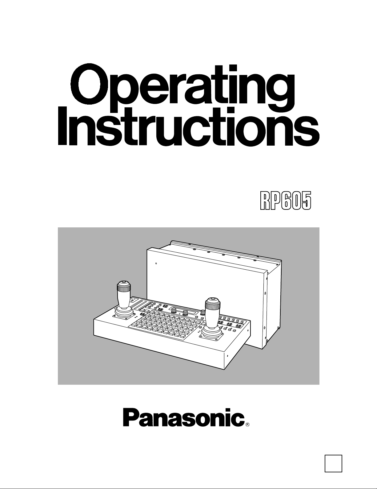
Multi-Function Controller
F1101W2052
@
Printed in Japan
VQT9557-2
P
2
FCC Note:
This device complies with Part 15 of the FCC Rules.
To assure continued compliance follow the attached
installation instructions and do not make any
unauthorized modifications.
This equipment has been tested and found to comply
with the limits for a class A digital device, pursuant to
Part 15 of the FCC Rules. These limits are designed
to provide reasonable protection against harmful
interference when the equipment is operated in a
commercial environment. This equipment generates,
uses, and can radiate radio frequency energy and, if
not installed and used in accordance with the
instruction manual, may cause harmful interference to
radio communications. Operation of this equipment in
a residential area is likely to cause harmful
interference in which case the user will be required to
correct the interference at his own expense.
CAUTION:
Do not install or place this unit in a
bookcase, built-in cabinet or any other
confined space in order to maintain adequate
ventilation. Ensure that curtains and any
other materials do not obstruct the
ventilation to prevent risk of electric shock or
fire hazard due to overheating.
CAUTION
RISK OF ELECTRIC SHOCK
DO NOT OPEN
CAUTION: TO REDUCE THE RISK OF ELECTRIC SHOCK,
DO NOT REMOVE COVER (OR BACK).
NO USER SERVICEABLE PARTS INSIDE.
REFER TO SERVICING TO QUALIFIED SERVICE PERSONNEL.
The lightning flash with arrowhead symbol,
within an equilateral triangle, is intended to
alert the user to the presence of uninsulated
“dangerous voltage” within the product’s
enclosure that may be of sufficient magnitude
to constitute a risk of electric shock to
persons.
The exclamation point within an equilateral
triangle is intended to alert the user to the
presence of important operating and
maintenance (service) instructions in the
literature accompanying the appliance.
indicates safety information.
WARNING:
TO REDUCE THE RISK OF FIRE OR SHOCK
HAZARD, DO NOT EXPOSE THIS
EQUIPMENT TO RAIN OR MOISTURE.
CAUTION:
TO REDUCE THE RISK OF FIRE OR SHOCK
HAZARD AND ANNOYING INTERFERENCE,
USE THE RECOMMENDED ACCESSORIES
ONLY.
Replace battery with part No. CR2032 only.
Use of another battery may present a risk of fire or
explosion.
Caution—Battery may explode if mistreated.
Do not recharge, disassemble or dispose of in fire.

3
Contents
Introduction . . . . . . . . . . . . . . . . . . . . . . . . . . . . . . . . . . . .3
Accessories . . . . . . . . . . . . . . . . . . . . . . . . . . . . . . . . . . . .3
Parts and their functions . . . . . . . . . . . . . . . . . . . . . . . . .4
Control panel . . . . . . . . . . . . . . . . . . . . . . . . . . . . . . . . . .4
Main unit . . . . . . . . . . . . . . . . . . . . . . . . . . . . . . . . . . . .12
Connections . . . . . . . . . . . . . . . . . . . . . . . . . . . . . . . . . .16
Operation . . . . . . . . . . . . . . . . . . . . . . . . . . . . . . . . . . . . .20
Turning on the power . . . . . . . . . . . . . . . . . . . . . . . . . . .20
Setting the travel range (limiters) of the pan-tilt head . .20
Setting the video signals . . . . . . . . . . . . . . . . . . . . . . . .21
Video signal cable compensation . . . . . . . . . . . . . . . . .22
Genlock adjustment . . . . . . . . . . . . . . . . . . . . . . . . . . . .25
Total pedestal adjustment . . . . . . . . . . . . . . . . . . . . . . .28
White balance adjustment . . . . . . . . . . . . . . . . . . . . . . .29
Black balance adjustment . . . . . . . . . . . . . . . . . . . . . . .30
Tracing memory settings . . . . . . . . . . . . . . . . . . . . . . . .31
Preset memory settings . . . . . . . . . . . . . . . . . . . . . . . . .35
Setting menus . . . . . . . . . . . . . . . . . . . . . . . . . . . . . . . . .36
Installing additional video boards . . . . . . . . . . . . . . . . .41
Inserting an optional card . . . . . . . . . . . . . . . . . . . . . . .41
Attaching the rack mounting adapters . . . . . . . . . . . . .42
Replacement of consumable parts . . . . . . . . . . . . . . . .42
Specifications . . . . . . . . . . . . . . . . . . . . . . . . . . . . . . . . .43
Accessories
Connecting cable (10m) . . . . . . . . . . . . . . . . . . . . . . . . . .1
Intercom jack (M6 jack) . . . . . . . . . . . . . . . . . . . . . . . . . . .1
Plug (Mini DIN 6-pin) for inter-communications
system . . . . . . . . . . . . . . . . . . . . . . . . . . . . . . . . . . . . . . . .1
Rack mounting adapters (5U) . . . . . . . . . . . . . . . . . . . . .4
Mounting screws (M4a8 mm) . . . . . . . . . . . . . . . . . . . . .8
Pan-tilt heads supported
AW-PH300, AW-PH300A, AW-PH350, AW-PH500,
AW-PH600
<Note>
The camera function cannot be controlled when the
AW-PH500 is used.
Introduction
O This multi-function controller is used to control one or
more pan-tilt head systems (each of which consists of a
pan-tilt head and convertible camera) and at the same
time provide video signal cable compensation.
It consists of a main unit which processes the signals and
a control panel for operating the pan-tilt head system or
systems, and these two parts are connected by the
connecting cable (10 m) supplied.
O Up to three control panels can be connected to the main
unit.
The cable supplied with the control panel and a 10BaseT
straight cable (UTP category 5) are used for the
connection.
A headset for inter-communication purposes can be
connected to the control panel to enable communication
between the control panels.
O Up to five pan-tilt head systems can be connected to the
main unit, and composite systems or component systems
can be supported.
However, when a component system is to be supported,
the AW-PB302 RGB card (optional accessory) must be
installed in the convertible camera.
O When the AW-PH350 is used as the pan-tilt head, the
connection between the main unit and pan-tilt head
system can be extended up to 1,000 meters.
When any other pan-tilt head model is used, it can be
extended up to 800 meters.
Use the dedicated AC adapter (AW-PS505) for the power supply.
When the AW-PS505 is used as the power source, 4 additional AW-PB605 boards (optional accessory) can be
installed in this unit, making it possible to use up to 5 video boards in total.
Note that when any optional boards are installed, the AJ-B75 AC adapter (optional accessory) should be used if
the total power consumption, including that of this unit, exceeds 30 W.
4
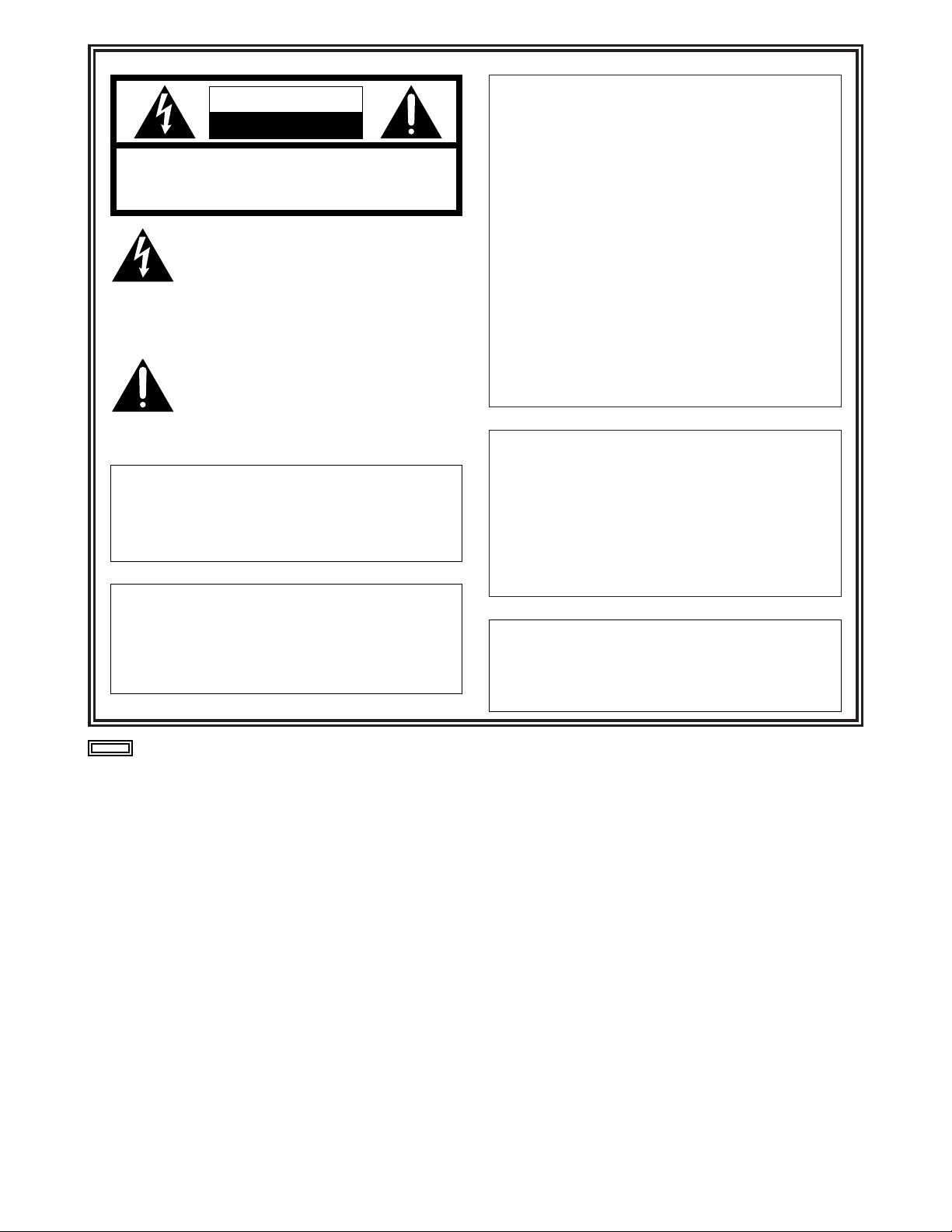
1 OPERATE lamp
This comes on when power is supplied to the main unit
and both the DC POWER switch on the main unit and the
OPERATE switch on the control panel are set to ON.
It goes off when either switch is set to OFF.
It flashes when a disconnection or some other problem
has occurred with the cable which is used to connect the
main unit and control panel.
2 OPERATE switch
This is used to control the power supply of all the pan-tilt
head systems (each of which consists of a pan-tilt head
and convertible camera) which have been connected to
the main unit.
3 INCOM connector
The headset for inter-communications purposes is
connected here.
4 LEVEL control
This is used to adjust the volume of the headset’s
receiver.
5 CALL button
When this button is pressed, the buzzers on the other
connected control panels sound, and the CALL button’s
lamp comes on.
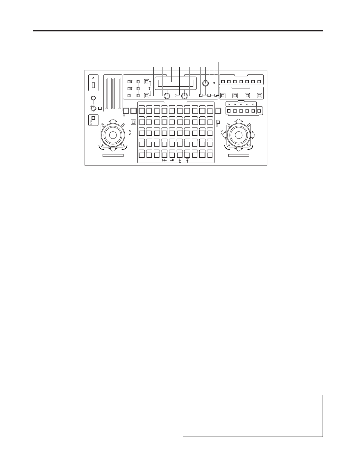
6 IRIS [AUTO/MAN/LOCK] button
This is used to select how to adjust the lens iris of the
pan-tilt head system currently selected.
Each time it is pressed, the AUTO, MANU or LOCK
setting is selected in turn.
AUTO
: The lens iris is adjusted automatically, and the
IRIS button’s lamp comes on. If the FOCUS/IRIS
dial for adjusting the iris is rotated when AUTO
has been selected, the IRIS button’s lamp flashes
as a warning.
MANU
: The lens iris is adjusted manually using the
FOCUS/IRIS dial.
At this setting, the IRIS button’s lamp goes off.
LOCK
: The lens iris is fixed at the position where it was
adjusted manually, and the IRIS button’s lamp
flashes.
At the LOCK setting, the position of the lens iris
will not be changed even if the FOCUS/IRIS dial
is turned.
<Note>
Set the button to the MANU position when entering the
lens iris position in the TRACING/PRESET MEMORY
button.
7 IRIS indicator
This indicates the lens iris position of the pan-tilt head
system currently selected using 12 steps (from CLOSE to
OPEN).
8 ZOOM indicator
This indicates the lens zoom position of the pan-tilt head
system currently selected using 12 steps (from WIDE to
TELE).
9 FOCUS indicator
This indicates the lens focus position of the pan-tilt head
system currently selected using 12 steps (from NEAR to
FAR).
Parts and their functions
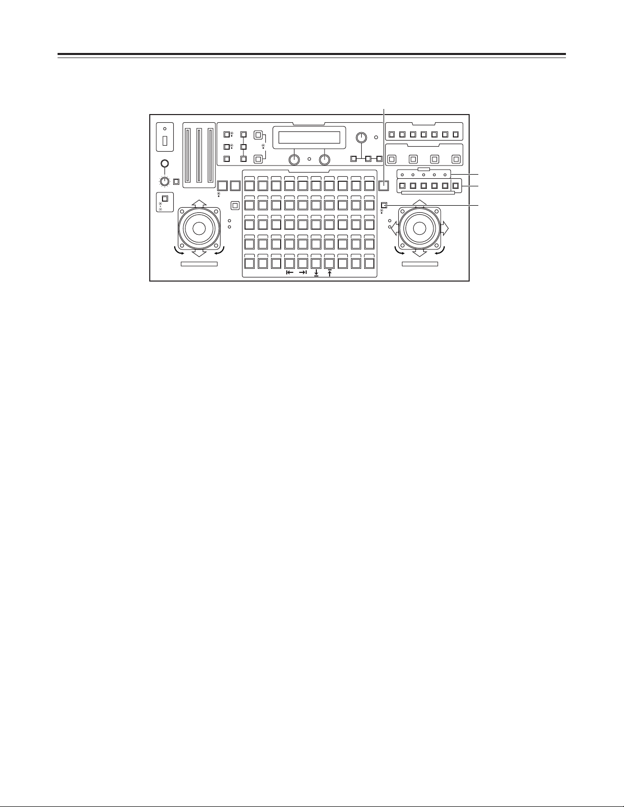
$ Control panel
CONTROL/PREVIEW MONITOR OUT SEL
AUX12345
TALLY
TRACING MEMORY
LAMP
MENU
LIMIT
OFF
LIMIT
ON
FULLEMPTY
OK
LCD
CONTRAST
CAMERA
CONTROL
START
POINT
R/B
GAIN/PED
WHITE
BAL
AWC
GAIN
MODE
CLOSE
WIDE NEAR
DATA SET
TR/PSET M.LOCK
MEMORY
IRIS
IRIS
IRIS
OPEN
ZOOM
TELE
FOCUS
FAR
CALL
INCOM
LEVEL
FOCUS
OPEN
FAR
TELE
OFF
ON
OPERATE
WIDE
ZOOM/FOCUS/IRIS
ABC
ATW
A
B
NG
OK
START/STOP RESTORE RESET
DEF WIP H/F EXT ND
OPTION
PAN/TILT SET
CAMERA CONTROL
TRACING/PRESET MEMORY
IRIS
SPEED
PRIORITY
FOCUS
BAR
CAM
TR
PSET
LOW
HIGH
AUTO
MANU
AUTO
MANU
LOCK
1 2 3 4 5 6 7 8 9 10
11 12 13 14 15 16 17 18 19 20
21 22 23 24 25 26 27 28 29 130
31 32 33 34 35 36 37 38 39 40
41 42 43 44 45 46 47 48 49 50
DOWN
PAN/TILT/FOCUS/IRIS
UP
LR
CLOSE
NEAR
OPEN
FAR
CLOSE
NEAR
7 8 95
1
2
3
4
6
<Note>
The IRIS, ZOOM and FOCUS indicator displays may not
appear depending on the model of pan-tilt head and
camera used.
Contact your local dealer for details.
5
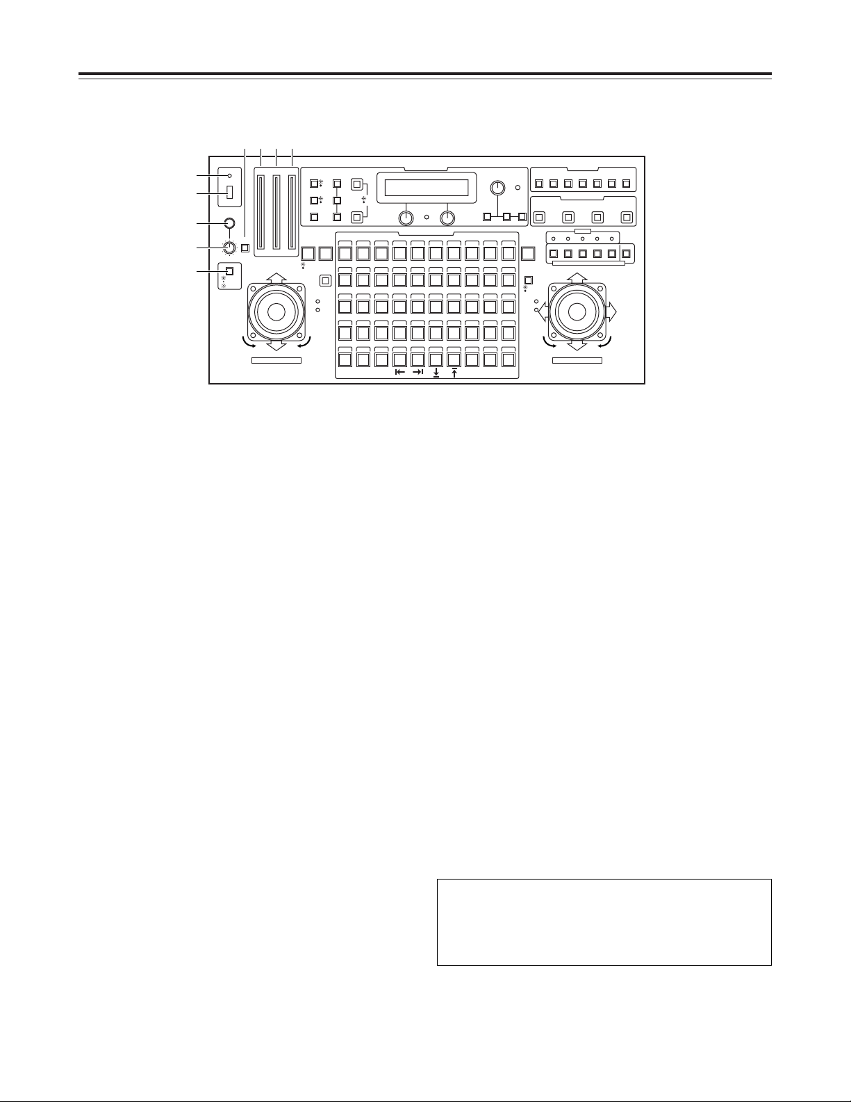
: GAIN [AUTO/MAN] button
This is used to select the camera’s gain control mode in
the pan-tilt head system currently selected.
Each time it is pressed, the AUTO mode or MANUAL
mode is selected in turn.
In the AUTO mode, the button’s lamp comes on; in the
MANUAL mode it goes off.
If, in the AUTO mode, the R/B GAIN/PED button is
pressed and the gain is adjusted, the maximum gain can
be set to one of two levels: AGC L or AGC H.
If, in the MANUAL mode, the R/B GAIN/PED button is
pressed and the gain is adjusted, any setting from 0 dB to
the night eye mode can be selected for the gain.
; MODE [BAR/CAM] button
This is used to select the camera’s video output signals in
the pan-tilt head system currently selected.
Each time it is pressed, the camera’s color bar signals or
video signals are selected in turn.
When the color bar signals are selected, the button’s
lamp comes on; when the video signals are selected, it
goes off.
< DATA SET button
At times when the multi-function controller has not
recognized a particular pan-tilt head system, such as
when the power to the pan-tilt head systemis turned on
or when a particular pan-tilt head system has been
connected after the multi-function controller’s OPERATE
switch has been set to ON, select the pan-tilt head
system concerned, and then press the DATA SET button.
The power of the selected pan-tilt head system will be
turned on, and the camera’s initial settings will be started.
= WHITE BAL [A/B/ATW] buttons
These are used to select the camera’s white balance
adjustment in the pan-tilt head system currently selected.
A:When the A button is pressed, the white balance
status entered in the camera’s memory A is
established, and the A button’s lamp comes on.
If the AWC button is pressed after the A button
was pressed, the white balance is automatically
adjusted and entered in the camera’s memory A.
B:When the B button is pressed, the white balance
status entered in the camera’s memory B is
established, and the B button’s lamp comes on.
If the AWC button is pressed after the B button
was pressed, the white balance is automatically
adjusted and entered in the camera’s memory B.
ATW
: When the ATW button is pressed, the white
balance is set to the automatic adjustment mode,
and the ATW button’s lamp comes on.
> AWC button
When the WHITE BAL [A] button or [B] button has been
selected, press the AWC button to automatically adjust
the white balance and enter the adjustment in the
camera’s memory A or memory B.
While the white balance is being adjusted, the AWC
button’s lamp flashes; when it has been adjusted
properly, it goes off. It comes on when it was not possible
to perform the adjustment.
<Notes>
O This function does not work if the MODE button has
been set to BAR (the MODE button’s lamp is lighted)
or if ATW has been selected.
O It may not be possible to adjust the white balance if
there is no white object on the screen being shot.
O If a pan-tilt head other than the AW-PH350 is being
used, the AWC button’s lamp also goes off if the white
balance was not adjusted properly.
Parts and their functions
$ Control panel
CONTROL/PREVIEW MONITOR OUT SEL
AUX12345
TALLY
TRACING MEMORY
LAMP
MENU
LIMIT
OFF
LIMIT
ON
FULLEMPTY
OK
LCD
CONTRAST
CAMERA
CONTROL
START
POINT
R/B
GAIN/PED
WHITE
BAL
AWC
GAIN
MODE
CLOSE
WIDE NEAR
DATA SET
TR/PSET M.LOCK
MEMORY
IRIS
IRIS
IRIS
OPEN
ZOOM
TELE
FOCUS
FAR
CALL
INCOM
LEVEL
FOCUS
OPEN
FAR
TELE
OFF
ON
OPERATE
WIDE
ZOOM/FOCUS/IRIS
ABC
ATW
A
B
NG
OK
START/STOP RESTORE RESET
DEF WIP H/F EXT ND
OPTION
PAN/ TILT SET
CAMERA CONTROL
TRACING/PRESET MEMORY
IRIS
SPEED
PRIORITY
FOCUS
BAR
CAM
TR
PSET
LOW
HIGH
AUTO
MANU
AUTO
MANU
LOCK
1 2 3 4 5 6 7 8 9 10
11 12 13 14 15 16 17 18 19 20
21 22 23 24 25 26 27 28 29 130
31 32 33 34 35 36 37 38 39 40
41 42 43 44 45 46 47 48 49 50
DOWN
PAN/TILT/FOCUS/IRIS
UP
LR
CLOSE
NEAR
OPEN
FAR
CLOSE
NEAR
: >;< =
6
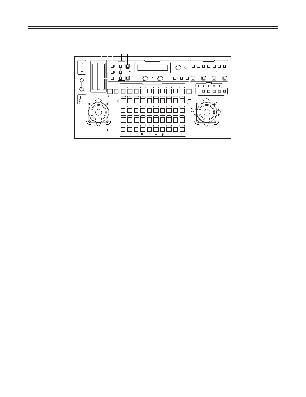
? ABC button
This is used to automatically adjust camera’s black
balance in the pan-tilt head system currently selected.
Set the IRIS [AUTO/MANU/LOCK] button to AUTO (the
IRIS button is now lighted), and press the ABC button.
While the black balance is being adjusted, the ABC
button’s lamp flashes; when it has been adjusted
properly, it goes off. It comes on when it was not possible
to perform the adjustment.
<Note>
If a pan-tilt head other than the AW-PH350 is being used,
the ABC button’s lamp also goes off if the black balance
was not adjusted properly.
@ LCD panel
This displays the statuses of the current settings.
A CAMERA CONTROL lamp
This comes on when communication with the camera in
the currently selected pan-tilt head system has been
established properly. It goes off when there is a problem
with the communication.
<Note>
If a pan-tilt head other than the AW-PH350 is being used,
the lamp will remain off even if communication has been
established properly.
B Menu setting control (L)
This is used to change the item or the value of the item
displayed on the left at the bottom of the LCD panel in the
setting menu mode.
C Menu setting control (R)
This is used to change the item or the value of the item
displayed on the right at the bottom of the LCD panel in
the setting menu mode.
D Menu setting control (main)
This is used to select the item or change the value of the
item displayed at the top of the LCD panel in the setting
menu mode.
E R/B GAIN/PED button
Press this button to adjust the camera’s R/B gain or R/B
pedestal in the pan-tilt head system currently selected.
Each time it is pressed, the adjustment mode is set to ON
or OFF in turn.
When the adjustment mode is set to ON, the button’s
lamp comes on; when it is OFF, the lamp goes off.
F MENU button
This is used to select ON or OFF for the setting menu
mode of the pan-tilt head system currently selected.
Each time it is pressed, the menu mode is set to ON or
OFF in turn.
When the setting menu mode is set to ON, the button’s
lamp comes on, and the setting menu appears on the
LCD panel. In this status, the MENU button is used to
select the setting menu items as well.
When the setting menu mode is set to OFF, the button’s
lamp goes off, and the LCD panel returns to its original
display.
G LCD CONTRAST control
This is used to adjust the contrast of the LCD panel.
H OK button
This is pressed to select setting menu items or to enter
the values of items.
Parts and their functions
$ Control panel
CONTROL/PREVIEW MONITOR OUT SEL
AUX12345
TALLY
TRACING MEMORY
LAMP
MENU
LIMIT
OFF
LIMIT
ON
FULLEMPTY
OK
LCD
CONTRAST
CAMERA
CONTROL
START
POINT
R/B
GAIN/PED
WHITE
BAL
AWC
GAIN
MODE
CLOSE
WIDE NEAR
DATA SET
TR/PSET M.LOCK
MEMORY
IRIS
IRIS
IRIS
OPEN
ZOOM
TELE
FOCUS
FAR
CALL
INCOM
LEVEL
FOCUS
OPEN
FAR
TELE
OFF
ON
OPERATE
WIDE
ZOOM/FOCUS/IRIS
ABC
ATW
A
B
NG
OK
START/STOP RESTORE RESET
DEF WIP H/F EXT ND
OPTION
PAN/ TILT SET
CAMERA CONTROL
TRACING/PRESET MEMORY
IRIS
SPEED
PRIORITY
FOCUS
BAR
CAM
TR
PSET
LOW
HIGH
AUTO
MANU
AUTO
MANU
LOCK
1 2 3 4 5 6 7 8 9 10
11 12 13 14 15 16 17 18 19 20
21 22 23 24 25 26 27 28 29 130
31 32 33 34 35 36 37 38 39 40
41 42 43 44 45 46 47 48 49 50
DOWN
PAN/TILT/FOCUS/IRIS
UP
LR
CLOSE
NEAR
OPEN
FAR
CLOSE
NEAR
? @ D
F H
G
EA CB
It is possible to switch the speed at which the setting value
of some of the items in the setting menu changes each
time jog dial B, C or D is pressed.
(See pages 36 and 37)
Note that this function may not work with the AW-RP615
Control Panel (optional accessory).
7
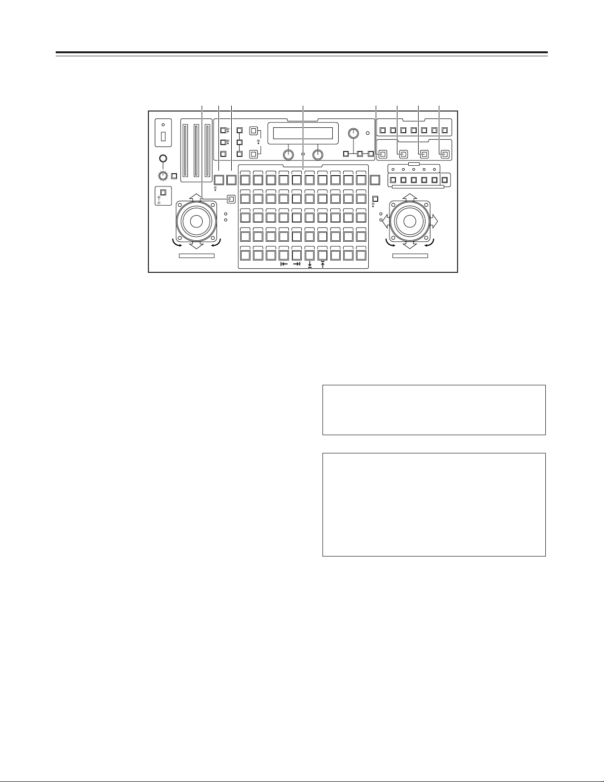
I LAMP button
This controls the ON and OFF of the halogen lamp which
is connected to the pan-tilt head system currently
selected.
Each time it is pressed, the lamp is turned ON or OFF in
turn.
When the halogen lamp is ON, the button’s lamp comes
on; when it is OFF, the lamp goes off.
It flashes when the halogen lamp has not been
connected or when the lamp has been disconnected or
some other problem has occurred.
J DEF button
This sets the defroster function ON or OFF when a pantilt head (AW-PH600) equipped with a defroster function
is used in the pan-tilt head system currently selected.
Each time it is pressed, the function is turned ON or OFF
in turn.
When the defroster is ON, the button’s lamp comes on;
when it is OFF, the lamp goes off.
K WIP button
This sets the wiper function ON or OFF when a pan-tilt
head (AW-PH600) equipped with a wiper function is used
in the pan-tilt head system currently selected.
Each time it is pressed, the function is turned ON or OFF
in turn.
When the wiper is ON, the button’s lamp comes on;
alternatively, when it is OFF, it goes off.
L H/F button
This sets the heater/fan function ON or OFF when a pantilt head (AW-PH600) equipped with a heater/fan function
is used in the pan-tilt head system currently selected.
Each time it is pressed, the function is turned ON or OFF
in turn.
When the heater/fan is ON, the button’s lamp comes on;
when it is OFF, the heater/fan goes off.
M EXT button
This sets the extender function ON or OFF when a lens
equipped with an extender function is used in the pan-tilt
head system currently selected.
Each time it is pressed, the function is turned ON or OFF
in turn.
When the extender is ON, the button’s lamp comes on;
when it is OFF, the lamp goes off.
N ND button
This sets the ND filter function ON or OFF when a lens
equipped with an ND filter function is used in the pan-tilt
head system currently selected.
Each time it is pressed, the function is turned ON or OFF
in turn.
When the ND filter is ON, the button’s lamp comes on;
when it is OFF, the lamp goes off.
O OPTION button
This controls the short- or open-circuiting of the OPTION
SW CONTROL OUT connector of the AC adapter (AWPS300) which is connected to the pan-tilt head system
currently selected.
Each time it is pressed, short-circuiting or open-circuiting
is selected in turn.
When the connector is short-circuited, the button’s lamp
comes on; when it is open-circuited, the lamp goes off.
Parts and their functions
$ Control panel
CONTROL/PREVIEW MONITOR OUT SEL
AUX12345
TALLY
TRACING MEMORY
LAMP
MENU
LIMIT
OFF
LIMIT
ON
FULLEMPTY
OK
LCD
CONTRAST
CAMERA
CONTROL
START
POINT
R/B
GAIN/PED
WHITE
BAL
AWC
GAIN
MODE
CLOSE
WIDE NEAR
DATA SET
TR/PSET M.LOCK
MEMORY
IRIS
IRIS
IRIS
OPEN
ZOOM
TELE
FOCUS
FAR
CALL
INCOM
LEVEL
FOCUS
OPEN
FAR
TELE
OFF
ON
OPERATE
WIDE
ZOOM/FOCUS/IRIS
ABC
ATW
A
B
NG
OK
START/STOP RESTORE RESET
DEF WIP H/F EXT ND
OPTION
PAN/ TILT SET
CAMERA CONTROL
TRACING/PRESET MEMORY
IRIS
SPEED
PRIORITY
FOCUS
BAR
CAM
TR
PSET
LOW
HIGH
AUTO
MANU
AUTO
MANU
LOCK
1 2 3 4 5 6 7 8 9 10
11 12 13 14 15 16 17 18 19 20
21 22 23 24 25 26 27 28 29 130
31 32 33 34 35 36 37 38 39 40
41 42 43 44 45 46 47 48 49 50
DOWN
PAN/TILT/FOCUS/IRIS
UP
LR
CLOSE
NEAR
OPEN
FAR
CLOSE
NEAR
I J K L M N O
8
P START POINT button
Press this to set the position at which the tracing memory
is to be started.
Q START/STOP button
Press this to start or stop entry into the tracing memory.
R RESTORE button
Press this to correct or change what has been entered in
the tracing memory.
S RESET button
Press this to erase what has been entered in the tracing
memory.
T TR/PSET button
This is used to select the tracing memory mode or preset
memory mode.
Each time it is pressed, the tracing memory mode or
preset memory mode is selected in turn.
When the tracing memory mode is selected, the button’s
lamp comes on; when the preset memory mode is
selected, the lamp goes off.
U M.LOCK button
This is used to disable or enable the recording of settings
in the tracing memory or preset memory.
Each time it is pressed, recording disable or enable is
selected in turn.
When recording is disabled, the button’s lamp comes on;
when it is enabled, the lamp goes off.
V MEMORY button
This is pressed when the pan-tilt head system’s settings
are to be entered as a preset memory into one of the
TRACING/PRESET MEMORY buttons [1] through [50].
Up to 50 settings can be entered per pan-tilt head system
into a preset memory.
Pan-tilt head system’s settings
How to enter settings into the preset memory
W TRACING/PRESET MEMORY buttons [1] to [50]
Tracing memory or preset memory data is entered into
these buttons.
Tracing memory: [1] through [10]
Preset memory : [1] through [50]
<Note>
It is not possible to enter preset memory data into any
button in which a tracing memory has already been
entered.
1 Select the pan-tilt head system using the
CONTROL/PREVIEW MONITOR OUT SEL button.
2 Select the preset memory mode using the
TP/PSET button.
3 Set the pan-tilt head system.
4 While pressing the MEMORY button, press one of
the TRACING/PRESET MEMORY buttons from [1]
through [50] into which the settings are to be
entered.
Pan-tilt head:
Pan-tilt position
Camera:
Zoom, focus, iris, white balance
Parts and their functions
$ Control panel
CONTROL/PREVIEW MONITOR OUT SEL
AUX12345
TALLY
TRACING MEMORY
LAMP
MENU
LIMIT
OFF
LIMIT
ON
FULLEMPTY
OK
LCD
CONTRAST
CAMERA
CONTROL
START
POINT
R/B
GAIN/PED
WHITE
BAL
AWC
GAIN
MODE
CLOSE
WIDE NEAR
DATA SET
TR/PSET M.LOCK
MEMORY
IRIS
IRIS
IRIS
OPEN
ZOOM
TELE
FOCUS
FAR
CALL
INCOM
LEVEL
FOCUS
OPEN
FAR
TELE
OFF
ON
OPERATE
WIDE
ZOOM/FOCUS/IRIS
ABC
ATW
A
B
NG
OK
START/STOP RESTORE RESET
DEF WIP H/F EXT ND
OPTION
PAN/TILT SET
CAMERA CONTROL
TRACING/PRESET MEMORY
IRIS
SPEED
PRIORITY
FOCUS
BAR
CAM
TR
PSET
LOW
HIGH
AUTO
MANU
AUTO
MANU
LOCK
1 2 3 4 5 6 7 8 9 10
11 12 13 14 15 16 17 18 19 20
21 22 23 24 25 26 27 28 29 130
31 32 33 34 35 36 37 38 39 40
41 42 43 44 45 46 47 48 49 50
DOWN
PAN/TILT/FOCUS/IRIS
UP
LR
CLOSE
NEAR
OPEN
FAR
CLOSE
NEAR
PT U WV Q R S
9
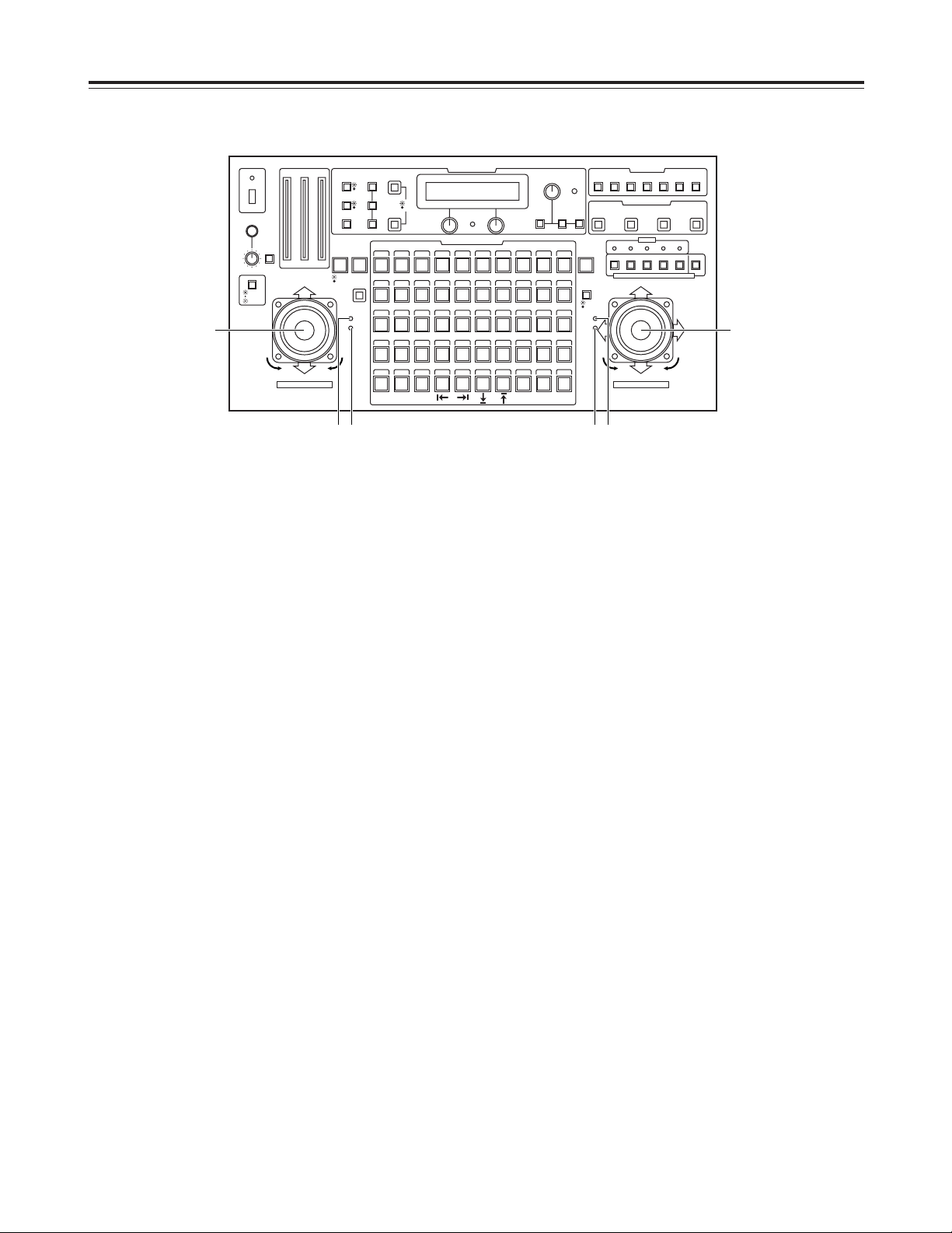
X ZOOM lever, FOCUS/IRIS dial
These are used to adjust the lens zoom in the pan-tilt
head system currently selected.
Depending on the direction in which the ZOOM lever is
tilted, TELE (telephoto) or WIDE (wide angle) is set, and
depending on the angle at which it is tilted, the zoom
speed is adjusted.
The lens focus or lens iris is adjusted using the dial at the
top of the lever.
Using the button on the top of the lever, the dial’s function
can be switched so that the dial will serve as a focus
adjustment dial or iris adjustment dial.
When the focus adjustment dial function has been
selected, the FOCUS lamp on the right of the lever
comes on; alternatively, when the iris adjustment dial
function has been selected, the IRIS lamp comes on.
<Note>
When the ZOOM lever dial functions as an iris
adjustment dial, the PAN/TILT lever dial on the other side
functions as a focus adjustment dial, and the FOCUS
lamp on the left of the PAN/TILT lever comes on.
Similarly, when the ZOOM lever dial functions as a focus
adjustment dial, the PAN/TILT lever dial on the other side
functions as an iris adjustment dial, and the IRIS lamp on
the left of the PAN/TILT lever comes on.
Y IRIS lamp
This comes on when the dial on the top of the ZOOM
lever functions as an iris adjustment dial.
Z FOCUS lamp
This comes on when the dial on the top of the ZOOM
lever functions as a focus adjustment dial.
Parts and their functions
$ Control panel
CONTROL/PREVIEW MONITOR OUT SEL
AUX12345
TALLY
TRACING MEMORY
LAMP
MENU
LIMIT
OFF
LIMIT
ON
FULLEMPTY
OK
LCD
CONTRAST
CAMERA
CONTROL
START
POINT
R/B
GAIN/PED
WHITE
BAL
AWC
GAIN
MODE
CLOSE
WIDE NEAR
DATA SET
TR/PSET M.LOCK
MEMORY
IRIS
IRIS
IRIS
OPEN
ZOOM
TELE
FOCUS
FAR
CALL
INCOM
LEVEL
FOCUS
OPEN
FAR
TELE
OFF
ON
OPERATE
WIDE
ZOOM/FOCUS/IRIS
ABC
ATW
A
B
NG
OK
START/STOP RESTORE RESET
DEF WIP H/F EXT ND
OPTION
PAN/ TILT SET
CAMERA CONTROL
TRACING/PRESET MEMORY
IRIS
SPEED
PRIORITY
FOCUS
BAR
CAM
TR
PSET
LOW
HIGH
AUTO
MANU
AUTO
MANU
LOCK
1 2 3 4 5 6 7 8 9 10
11 12 13 14 15 16 17 18 19 20
21 22 23 24 25 26 27 28 29 130
31 32 33 34 35 36 37 38 39 40
41 42 43 44 45 46 47 48 49 50
DOWN
PAN/TILT/FOCUS/IRIS
UP
LR
CLOSE
NEAR
OPEN
FAR
CLOSE
NEAR
X
ZY
[
]\
[ PAN/TILT lever, FOCUS/IRIS dial
These are used to adjust the direction of the pan-tilt head
in the pan-tilt head system currently selected.
When the PAN/TILT lever is panned in the L/R direction,
the pan-tilt head direction changes to the left or right;
when it is tilted in the UP/DOWN direction, it changes in
the up or down direction.
The speed is adjusted by the angle to which the lever is
tilted.
The lens focus or lens iris is adjusted using the dial at the
top of the lever.
Using the button on the top surface of the lever, the dial’s
function can be switched so that the dial will serve as a
focus adjustment dial or iris adjustment dial.
When the focus adjustment dial function has been
selected, the FOCUS lamp on the left of the lever comes
on; alternatively, when the iris adjustment dial function
has been selected, the IRIS lamp comes on.
<Note>
When the PAN/TILT lever dial functions as an iris
adjustment dial, the ZOOM lever dial on the other side
functions as a focus adjustment dial, and the FOCUS
lamp on the right of the ZOOM lever comes on.
Similarly, when the PAN/TILT lever dial functions as a
focus adjustment dial, the ZOOM lever dial on the other
side functions as an iris adjustment dial, and the IRIS
lamp on the right of the ZOOM lever comes on.
\ IRIS lamp
This comes on when the dial on the top of the PAN/TILT
lever functions as an iris adjustment dial.
] FOCUS lamp
This comes on when the dial on the top of the PAN/TILT
lever functions as a focus adjustment dial.
10
Parts and their functions
$ Control panel
CONTROL/PREVIEW MONITOR OUT SEL
AUX12345
TALLY
TRACING MEMORY
LAMP
MENU
LIMIT
OFF
LIMIT
ON
FULLEMPTY
OK
LCD
CONTRAST
CAMERA
CONTROL
START
POINT
R/B
GAIN/PED
WHITE
BAL
AWC
GAIN
MODE
CLOSE
WIDE NEAR
DATA SET
TR/PSET M.LOCK
MEMORY
IRIS
IRIS
IRIS
OPEN
ZOOM
TELE
FOCUS
FAR
CALL
INCOM
LEVEL
FOCUS
OPEN
FAR
TELE
OFF
ON
OPERATE
WIDE
ZOOM/FOCUS/IRIS
ABC
ATW
A
B
NG
OK
START/STOP RESTORE RESET
DEF WIP H/F EXT ND
OPTION
PAN/ TILT SET
CAMERA CONTROL
TRACING/PRESET MEMORY
IRIS
SPEED
PRIORITY
FOCUS
BAR
CAM
TR
PSET
LOW
HIGH
AUTO
MANU
AUTO
MANU
LOCK
1 2 3 4 5 6 7 8 9 10
11 12 13 14 15 16 17 18 19 20
21 22 23 24 25 26 27 28 29 130
31 32 33 34 35 36 37 38 39 40
41 42 43 44 45 46 47 48 49 50
DOWN
PAN/TILT/FOCUS/IRIS
UP
LR
CLOSE
NEAR
OPEN
FAR
CLOSE
NEAR
`
^
_
a
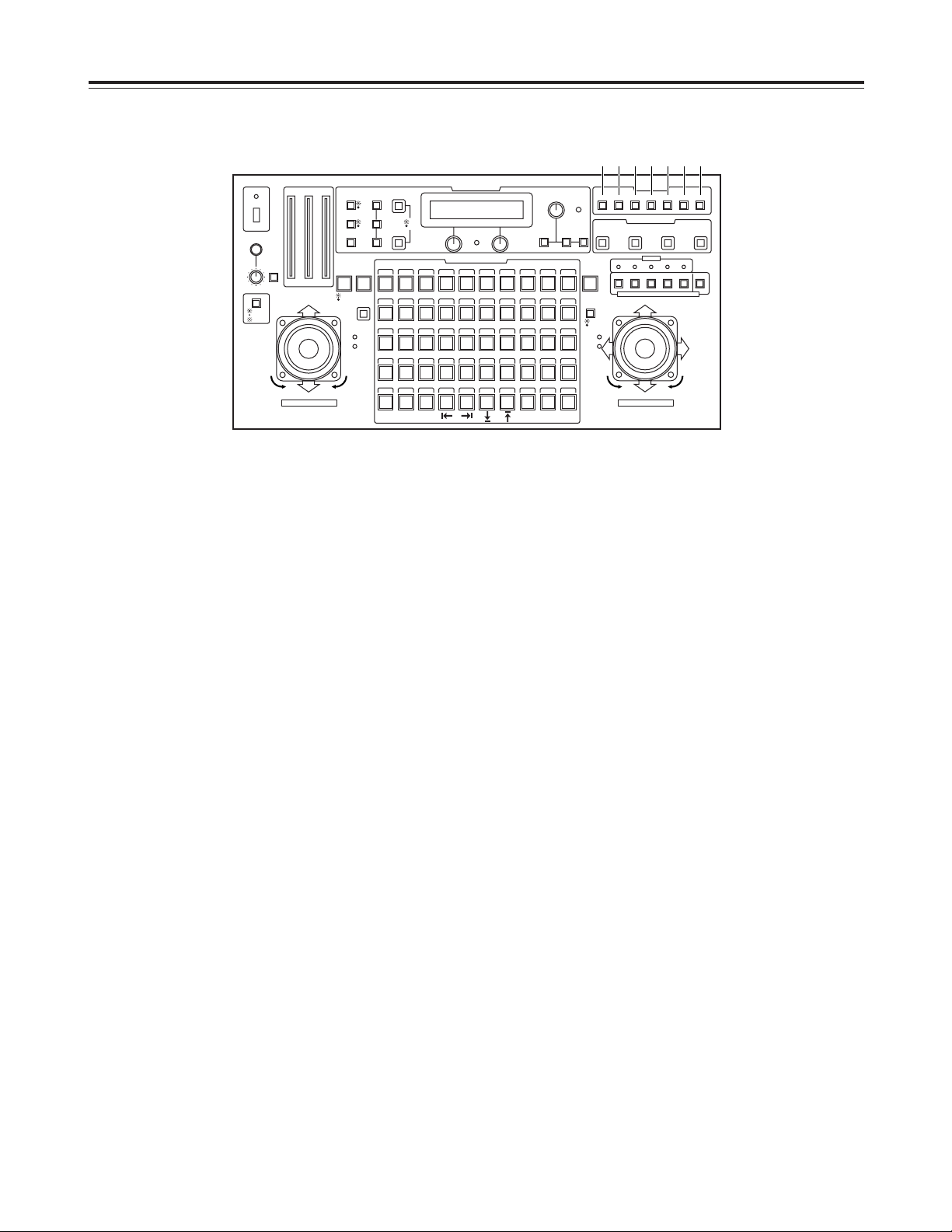
^ TALLY lamps [1] to [5]
When tally signals are input to TALLY connectors [1]
through [5] on the main unit, the lamps with the numbers
corresponding to the connectors come on.
_ CONTROL/PREVIEW MONITOR OUT SEL buttons
[1] to [5], [AUX]
When buttons [1] to [5] are pressed, the pan-tilt head
systems connected to the slots in the main unit are
selected.
The lamps of the selected buttons come on, and the
video signals from the selected pan-tilt head systems are
output to the PREVIEW MONITOR OUT 1 to 3
connectors on the main unit.
When the [AUX] button is pressed, the signals from the
equipment connected to the AUX IN 75Ω connector on
the main unit are output.
` PRIORITY button
When more than one control panel is connected to the
main unit, press this button to control the pan-tilt head
systems.
The button’s lamp comes on in the control mode, and it
remains off in the non-control mode.
When one control panel is connected to the main unit, the
button’s lamp is lighted at all times.
a SPEED button
This is used to select the control (pan, tilt, zoom, focus,
iris) speed of the pan-tilt head system currently selected.
Each time it is pressed, the high-speed mode or lowspeed mode is selected in turn.
The button’s lamp comes on in the high-speed mode, and
it remains off in the low-speed mode.
Using the SPEED SELECT item on the setting menu, the
speed can be set in one of three steps for the high-speed
mode and for the low-speed mode.
11
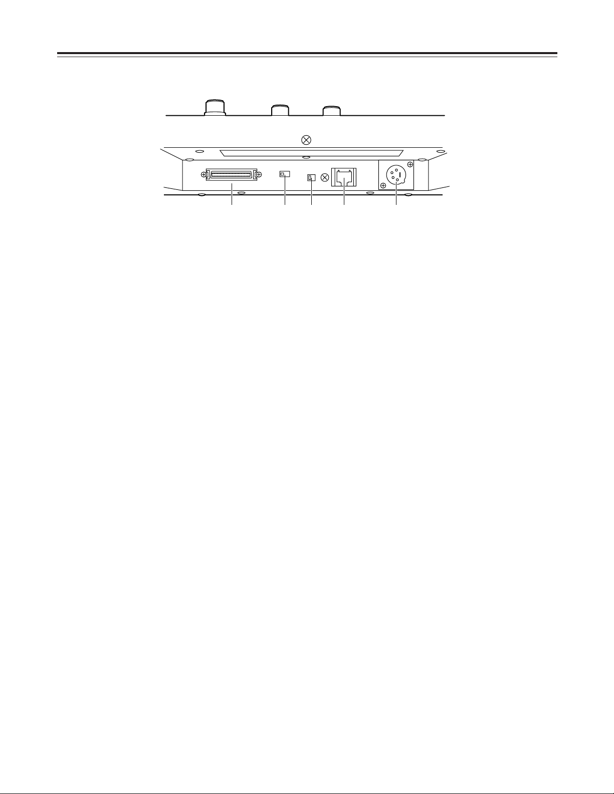
b DC 12V IN socket
The power from the main unit is supplied to this socket.
The socket is connected to the CONTROL PANEL
POWER OUT socket on the main unit using the
connecting cable (10 meters) supplied.
<Note>
If the connection distance exceeds 10 meters, connect
the AW-PS505 AC adapter (optional accessory).
c CONTROL OUT connector
The control signals are output from this connector to the
main unit. Use the connecting cable (10 meters) supplied
to connect the connector to the CONTROL IN TO
CONTROL PANEL [1] to [3] connectors on the main unit.
<Note>
If the connection distance exceeds 10 meters, use a
straight cable equivalent to 10BaseT (UTP category 5) to
make the connection. The connection distance can be
extended up to 1,000 meters.
When more than one control panel is to be connected to
the main unit, make sure that the total length of all the
cables does not exceed 1,000 meters.
d TERMINATION switch
This is the control signal termination switch.
<Notes>
O When one control panel is connected to the main unit,
set both this switch and the TERMINATION switch on
the main unit to the ON position.
O When two control panels are connected to the main
unit, set this switch on both panels to the ON position,
and set the TERMINATION switch on the main unit to
the OFF position.
O When three control panels are connected to the main
unit, set the switch on the control panel with the
shortest connecting cable to the main unit and the
TERMINATION switch on the main unit to the OFF
position, and set the switches on the other two control
panels to the ON position.
e ID switch
This is used to set the ID numbers of the control panels.
<Note>
Do not set the same ID number when more than one
control panel is to be connected to the main unit.
f SERVICE connector
This connector is used for maintenance purposes.
Do not connect anything to it.
Parts and their functions
$ Control panel
bcdef
12
1 POWER lamp
This lights up green when power is supplied to the main
unit and the DC POWER switch is set to ON. It goes off
when the switch is set to OFF.
2 DC POWER switch
This is the main unit’s power switch.
3 DC 12V IN socket
The AW-PS505 AC adapter (optional accessory) is
connected to this socket.
When the AW-PS505 is used as the power source, 4
additional AW-PB605 boards can be installed in this unit,
making it possible to use up to 5 video boards in total.
Note that when any optional boards are installed, the AJB75 AC adapter (optional accessory) should be used if
the total power consumption, including that of this unit,
exceeds 30 W.
4 CONTROL PANEL POWER OUT socket
The power for the control panels is output from this
socket.
The socket is connected to the DC 12V IN socket on the
control panel using the connecting cable (10 meters)
supplied.
<Notes>
O When the connection distance exceeds 10 meters,
connect the AW-PS505 AC adapter (optional
accessory) to the control panel instead of the
connecting cable supplied.
O When more than one control panel is to be connected,
connect the AW-PS505 AC adapter (optional
accessory) to an additional control panel.
5 CONTROL IN TO CONTROL PANEL connectors
[1] to [3]
The control signals are input from the control panels to
these connectors. Use the connecting cable (10 meters)
supplied to connect the connectors to the CONTROL
OUT connectors on the control panels.
<Note>
If the connection distance exceeds 10 meters, use a
straight cable equivalent to 10BaseT (UTP category 5) to
make the connection. The connection distance can be
extended up to 1,000 meters.
When more than one control panel is to be connected to
the main unit, make sure that the total length of all the
cables does not exceed 1,000 meters.
6 TERMINATION switch
This is the control signal termination switch.
<Notes>
O When one control panel is connected to the main unit,
set both this switch and the TERMINATION switch on
the control panel to the ON position.
O When two control panels are connected to the main
unit, set this switch to the OFF position, and set the
TERMINATION switches on the control panels to the
ON position.
O When three control panels are connected to the main
unit, set this switch and the TERMINATION switch on
the control panel with the shortest connecting cable to
the main unit to the OFF position, and set the
TERMINATION switches on the other two control
panels to the ON position.
7 EXTERNAL CONTROL OUT connector
This connector is intended to support additional functions.
It is not supported at the present time.
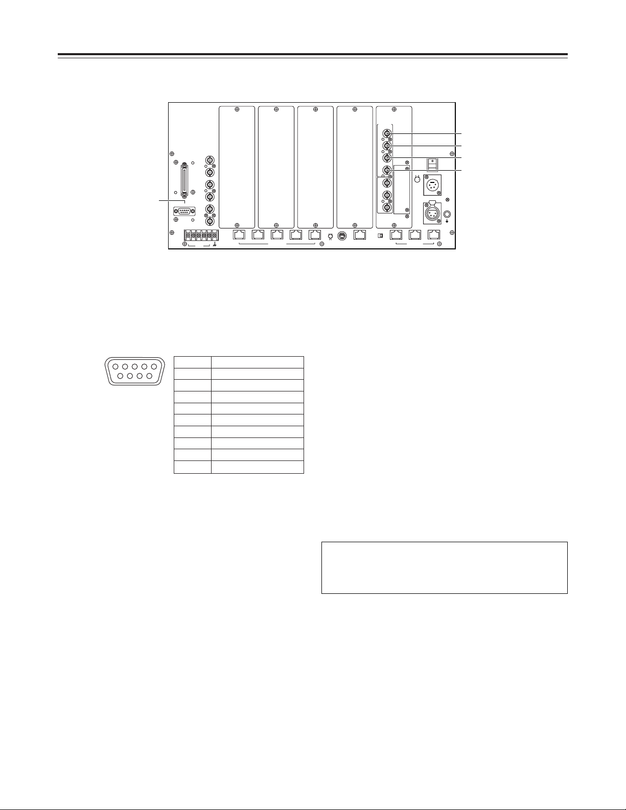
Parts and their functions
$ Main unit
G/L
IN
75Ω
AUTO
TALLY
12345
54
CONTROL OUT
TO PAN/TILT HEAD
321
EXT/
SERVICE
AUX
IN
75Ω
PREVIEW
MONITOR
OUT 1
PREVIEW
MONITOR
OUT 2
PREVIEW
MONITOR
OUT 3
INCOM
EXTERNAL
CONTROL
OUT
OFF ON
TERMINATION
TALK
-
RECEIVE-+RECEIVE
+
TALK
CONTROL IN
TO CONTOROL PANEL
CONTROL PANEL
POWER OUT
GND
DC 12V IN
PUSH
DC POWER
OFF
ON
321
12
43
56
-+
1
2
4
3
TO PAN/TILT
HEAD
VIDEO
/Y
IN
VIDEO
/Y
OUT
OPTION
CARD
Pr
OUT
Pb
OUT
Pr
IN
Pb
IN
G/L
OUT
REMOTE
67
2
3
4
1
5
P
O
W
E
R
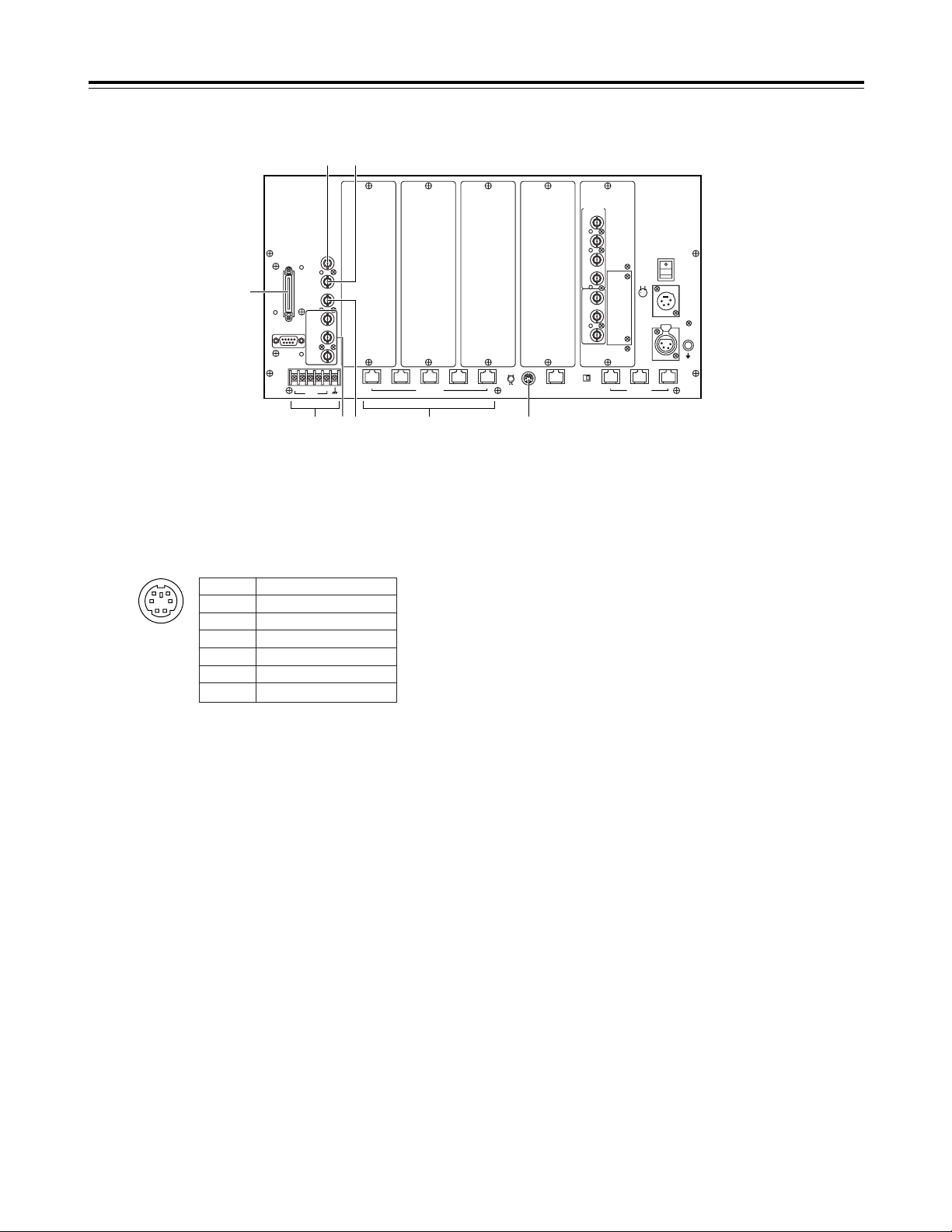
8 INCOM connector
This connector is used for connecting to the TALLY &
INCOM connector on the AW-SW300 live switcher, etc.
to enable inter-communication.
To perform inter-communication, use the intercommunication system plug (Mini DIN 6-pin) supplied.
9
CONTROL OUT TO PAN/TILT HEAD connectors [1] to [5]
Connect these connectors to the IP/RP connector on the
AW-PH350 pan-tilt head using a straight cable equivalent
to 10BaseT (UTP category 5). The connection distance
can be extended up to 1,000 meters.
When connecting one of these connectors to any other
pan-tilt head, use the RS-232C/RS-422 converter, and
connect the connector to the RS-232C control connector
on the pan-tilt head.
: TALLY connectors [1] to [5]
These connectors are used for connection with the
TALLY connector of a special effects generator, video
switcher or other equipments.
When the voltage which is supplied to terminal numbers
1 through 5 is set to the GND level, the TALLY lamps on
the control panels and the TALLY lamps on the pan-tilt
heads come on.
; G/L IN connector (automatic 75Ω termination)
When the pan-tilt head system cameras are to be
synchronized with external signals for use, connect a
coaxial cable to this connector, and supply a black burst
signal or VBS (video, burst and sync) signal.
When a coaxial cable is connected to the 75Ω AUTO
connector, the 75Ω termination is turned off.
< 75Ω AUTO connector
The black burst signal or VBS (video, burst and sync)
signal which is supplied to the G/L IN connector is output
from this connector by way of a loop-through format.
= AUX IN 75Ω connector
A coaxial cable is connected to this connector to supply
the line view signals, etc. from a special effects
generator, etc.
When the CONTROL/MONITOR OUT SEL AUX button
on the control panel is pressed, the signals supplied to
the AUX IN 75Ω connector are output from the PREVIEW
MONITOR OUT 1, 2 and 3 connectors.
> PREVIEW MONITOR OUT connectors 1, 2 and 3
One end of a coaxial cable is connected to one of these
connectors and the other end is connected to the video
input connector on a TV monitor.
When the CONTROL/MONITOR OUT SEL 1 to 5 buttons
on the control panel are pressed, the video signals from
the selected pan-tilt head system are output.
When the AUX button has been pressed, the signals
supplied to the AUX IN 75Ω connector are output.
<Note>
The signals which are output from these connectors are
used for image verification purposes. Signals
representing the actual quality of the images shot by the
camera are output from the VIDEO/Y OUT, Pr OUT and
Pb OUT connectors.
? EXT/SERVICE connector
This connector is intended to support additional functions.
It is not supported at the present time.
Pin No. Signal
1 RECEIVE +
2 RECEIVE –
3 TALK +
4 TALK –
5 ———
6 ———
1
2
4
3
56
13
Parts and their functions
$ Main unit
G/L
IN
75Ω
AUTO
TALLY
12345
54
CONTROL OUT
TO PAN/TILT HEAD
321
EXT/
SERVICE
AUX
IN
75Ω
PREVIEW
MONITOR
OUT 1
PREVIEW
MONITOR
OUT 2
PREVIEW
MONITOR
OUT 3
INCOM
EXTERNAL
CONTROL
OUT
OFF ON
TERMINATION
TALK
-
RECEIVE-+RECEIVE
+
TALK
CONTROL IN
TO CONTOROL PANEL
CONTROL PANEL
POWER OUT
GND
DC 12V IN
PUSH
DC POWER
OFF
ON
321
12
43
56
-+
1
2
4
3
TO PAN/TILT
HEAD
VIDEO
/Y
IN
VIDEO
/Y
OUT
OPTION
CARD
Pr
OUT
Pb
OUT
Pr
IN
Pb
IN
G/L
OUT
REMOTE
?
=
<;
9: >
8
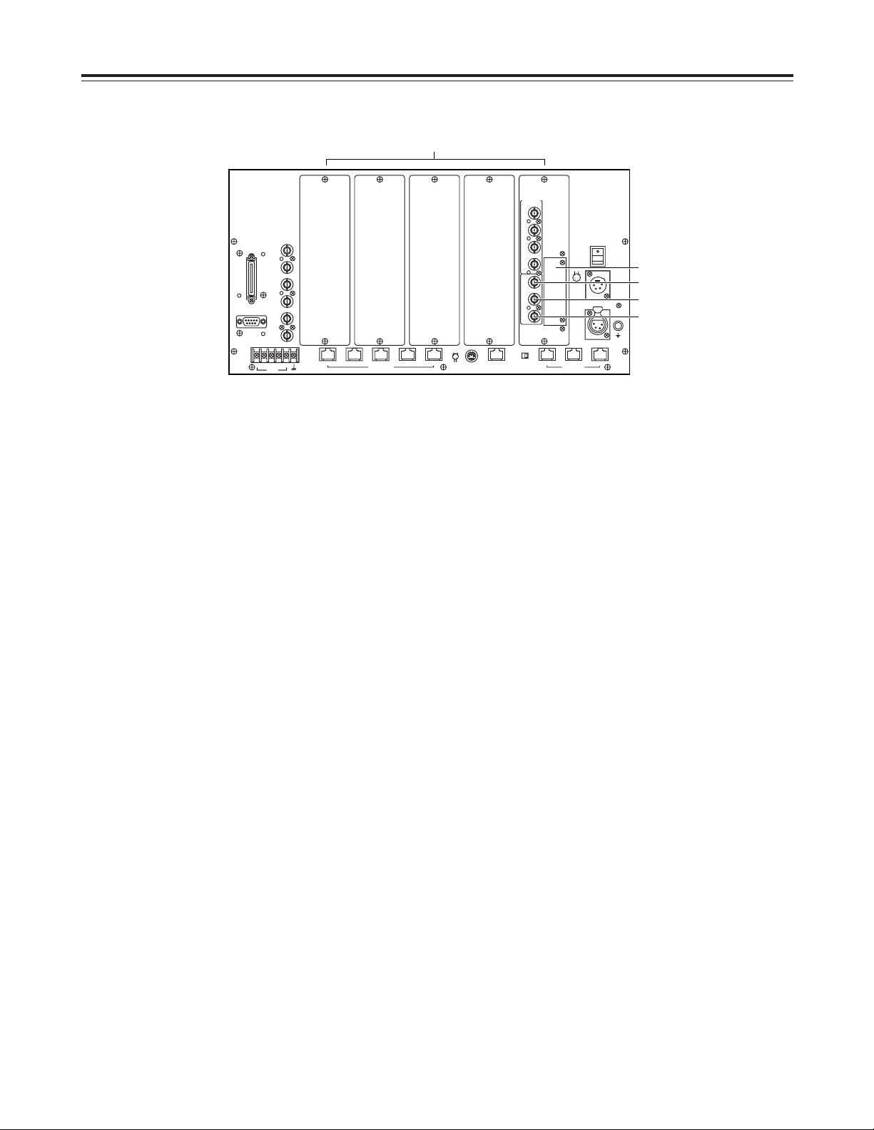
14
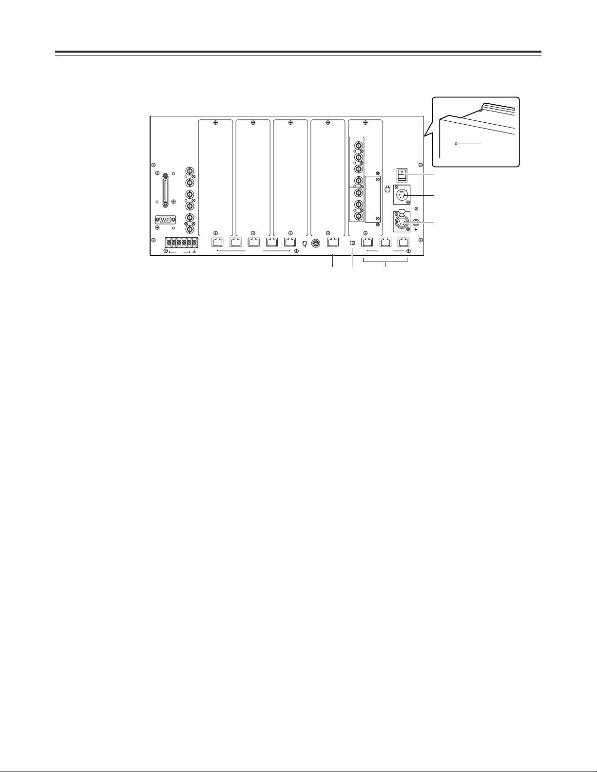
@ REMOTE connector
A personal computer or other external equipment is
connected here when a pan-tilt head system is to be
controlled by these equipments.
A VIDEO/Y IN connector
One end of a coaxial cable (equivalent to BELDEN 8281)
is connected here and the other end is connected to the
video output connector or Y/VIDEO output connector on
the pan-tilt head.
When the AW-PH350 is used as the pan-tilt head, a
connection distance of up to 1,000 meters is possible.
When any other pan-tilt head is used, a connection
distance of up to 800 meters is possible.
B Pr IN connector
When component signals are to be used as the video
signals, one end of the coaxial cable (equivalent to
BELDEN 8281) is connected here and the other end is
connected to the Pr signal output connector on the pantilt head.
When the AW-PH350 is used as the pan-tilt head, a
connection distance of up to 1,000 meters is possible.
When the AW-PH600 or AW-PH500 is used as the pantilt head, a connection distance of up to 800 meters is
possible.
C Pb IN connector
When component signals are to be used as the video
signals, one end of the coaxial cable (equivalent to
BELDEN 8281) is connected here and the other end is
connected to the Pb signal output connector on the pantilt head.
When the AW-PH350 is used as the pan-tilt head, a
connection distance of up to 1,000 meters is possible.
When the AW-PH600 or AW-PH500 is used as the pantilt head, a connection distance of up to 800 meters is
possible.
D G/L OUT connector
One end of a coaxial cable (equivalent to BELDEN 8281)
is connected here and the other end is connected to the
genlock signal input connector on the pan-tilt head.
When the AW-PH350 is used as the pan-tilt head, a
connection distance of up to 1,000 meters is possible.
When any other pan-tilt head is used, a connection
distance of up to 800 meters is possible.
Parts and their functions
$ Main unit
Pin No. Signal
1 ———
2 RXD IN
3 TXD OUT
4 DTR
5 GND
6 DSR
7 RTS
8 CTS
9 ———
96
15
<Note>
When component signals are to be used as the video
signals, the AW-PB302 RGB card (optional accessory)
must be installed in the convertible camera.
G/L
IN
75Ω
AUTO
TALLY
12345
54
CONTROL OUT
TO PAN/TILT HEAD
321
EXT/
SERVICE
AUX
IN
75Ω
PREVIEW
MONITOR
OUT 1
PREVIEW
MONITOR
OUT 2
PREVIEW
MONITOR
OUT 3
INCOM
EXTERNAL
CONTROL
OUT
OFF ON
TERMINATION
TALK
-
RECEIVE-+RECEIVE
+
TALK
CONTROL IN
TO CONTOROL PANEL
CONTROL PANEL
POWER OUT
GND
DC 12V IN
PUSH
DC POWER
OFF
ON
321
12
43
56
-+
1
2
4
3
TO PAN/TILT
HEAD
VIDEO
/Y
IN
VIDEO
/Y
OUT
OPTION
CARD
Pr
OUT
Pb
OUT
Pr
IN
Pb
IN
G/L
OUT
REMOTE
@
B
A
C
D
15
E VIDEO/Y OUT connector
The video signals adjusted by the cable compensation
circuit to match the length of the cable from the pan-tilt
head to the main unit are output from this connector.
One end of a coaxial cable is connected here and the
other end is connected to the video input connector or the
Y signal input connector on a TV monitor, special effects
generator, VTR or other equipments.
F Pr OUT connector
When component signals are supplied to the multifunction controller, the Pr signals adjusted by the cable
compensation circuit to match the length of the cable
from the pan-tilt head to the main unit are output from this
connector.
One end of a coaxial cable is connected here and the
other end is connected to the Pr input connector on a TV
monitor, special effects generator, VTR or other
equipments.
G Pb OUT connector
When component signals are supplied to the multifunction controller, the Pb signals adjusted by the cable
compensation circuit to match the length of the cable
from the pan-tilt head to the main unit are output from this
connector.
One end of a coaxial cable is connected here and the
other end is connected to the Pb input connector on a TV
monitor, special effects generator, VTR or other
equipments.
H OPTION CARD slot
When component signals are supplied to the multifunction controller, and an AW-PB302 RGB card, AWPB304 SDI card, AW-PB307 SVGA convert card or AWPB309 Web card (optional accessories) is installed in this
slot, signals utilizing the functions of the installed card
can be output.
For further details, refer to the operating instructions of
the card concerned.
<Notes>
O When an optional card is to be installed in the multi-
function controller, the AW-PB302 RGB card (optional
accessory) must be installed in the convertible
camera.
O A pan-tilt head system cannot be controlled through
network even if the AW-PB309 Web card has been
installed in the multi-function controller.
I VIDEO BOARD slots 1 to 5
Each pan-tilt head system requires one VIDEO board.
A VIDEO board is already installed in slot 1 and four
other AW-PB605 VIDEO boards (optional accessories)
can be installed to increase the number of pan-tilt head
systems.
<Notes>
O There is no need to install a VIDEO board if the multi-
function controller is employed merely to operate a
pan-tilt head system and not to process video signals.
O When any optional cards are installed, the AJ-B75 AC
adapter (optional accessory) should be connected to
the DC 12V IN socket if the total power consumption,
including that of this unit, exceeds 30 W.
Parts and their functions
$ Main unit
G/L
IN
75Ω
AUTO
TALLY
12345
54
CONTROL OUT
TO PAN/TILT HEAD
321
EXT/
SERVICE
AUX
IN
75Ω
PREVIEW
MONITOR
OUT 1
PREVIEW
MONITOR
OUT 2
PREVIEW
MONITOR
OUT 3
INCOM
EXTERNAL
CONTROL
OUT
OFF ON
TERMINATION
TALK
-
RECEIVE-+RECEIVE
+
TALK
CONTROL IN
TO CONTOROL PANEL
CONTROL PANEL
POWER OUT
GND
DC 12V IN
PUSH
DC POWER
OFF
ON
321
12
43
56
-+
1
2
4
3
TO PAN/TILT
HEAD
VIDEO
/Y
IN
VIDEO
/Y
OUT
OPTION
CARD
Pr
OUT
Pb
OUT
Pr
IN
Pb
IN
G/L
OUT
REMOTE
E
H
F
G
I

16
Connections
O Use the AW-PS505 (optional accessory) for the main
unit’s AC adapter and the AW-PS300 (optional
accessory) for the pan-tilt head’s AC adapter.
O Connect the DC 12V IN socket on the control panel with
the CONTROL PANEL POWER OUT connector on the
main unit, and the CONTROL OUT connector on the
control panel with the CONTROL IN TO CONTROL
PANEL connector 1 on the main unit using the cables (10
m) supplied.
To extend the connection distance between the control
panel and main unit beyond 10 meters, the AW-PS505
(optional accessory) as the power supply for the control
panel and a 10BaseT straight cable (for the control
signals) must be provided separately.
The maximum extension distance is 500 meters when the
10BaseT straight cable (equivalent to UTP category 5) is
used.
O Use a DC power cable (which has a nominal cross-
sectional area of at least 1.25 mm
2
and which complies
with the Electrical Appliance and Material Control Law) to
connect the AW-PH350 pan-tilt head and AW-PS300
pan-tilt head AC adapter.
The maximum extension distance between the AC
adapter for the pan-tilt head and the pan-tilt head itself is
30 meters.
O Connect the AW-PH350 pan-tilt head and convertible
camera using the composite camera cable (AWCA50T29) or component camera cable (AW-CA50C29).
O Connect the iris control cable of the motorized zoom lens
to the camera and the remote (zoom/focus control) cable
to the pan-tilt head.
When using composite signals
O The AW-CA50T29 (optional accessory) is required to
connect the convertible camera to the AW-PH350 pan-tilt
head.
O To connect the main unit and pan-tilt heads, use two
coaxial cables (one for the video signals and the other for
the G/L signals) and one 10BaseT straight cable (for the
camera/pan-tilt head control signals) for each pan-tilt
head.
The maximum extension distance is 1,000 meters for
each pan-tilt head (when coaxial cables equivalent to
BELDEN 8281 and a 10BaseT straight cable equivalent
to UTP category 5 are used).
When using component signals
O The AW-CA50C29 (optional accessory) is required to
connect the convertible camera to the AW-PH350 pan-tilt
head.
O To connect the main unit and pan-tilt heads, use four
coaxial cables (one each for the Y signals, Pr signals, Pb
signals and G/L signals) and one 10BaseT straight cable
(for the camera/pan-tilt head control signals) for each
pan-tilt head.
The maximum extension distance is 1,000 meters for
each pan-tilt head (when coaxial cables equivalent to
BELDEN 8281 and a 10BaseT straight cable equivalent
to UTP category 5 are used).
O When component signals are used, the RGB card (AW-
PB302) available as an optional accessory must be
installed in the convertible camera.
Turn off the power of all components before
proceeding with the connections.
For further details on how to connect each component,
refer to the operating instructions of the component
concerned.
G/L IN Pb OUT Pr /SDI
OUT
Y/VIDEO
OUT
1394
CONTROL IN
IP/RP
DC12V
IN
CAMERA I/F
LENSE I/F
ND/EXT
SDI
IN
CSOP
O I
FUSE
FUSE
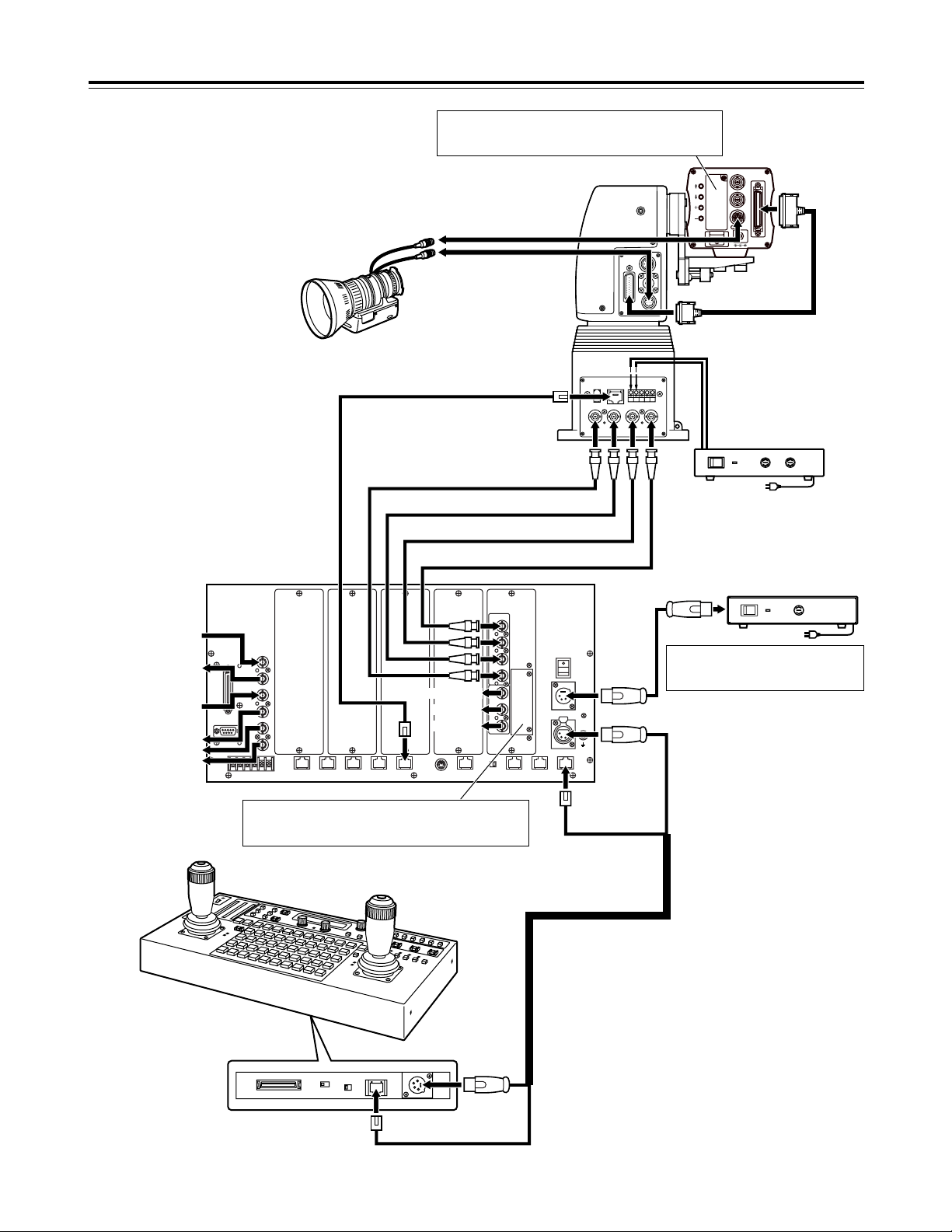
17
Connections
Pan-tilt head:
AW-PH350
Iris control
Convertible camera
Zoom lens
Zoom/focus control
AC adapter:
AW-PS300
Control panel
Connector cable
(accessory)
Main unit
AC adapter:
AW-PS505
Y/VIDEO signal
Pr signal
Pb signal
Y/VIDEO signal
Pr signal
Pb signal
G/L signal
G/L signal input
G/L through signal
output
AUX signal input
Video monitor output
Pan-tilt head system control signals
Pan-tilt head cable:
AW-CA50T29
(for composite signal)
AW-CA50C29
(for component signals)
When an optional card is to be installed in the multifunction controller, the AW-PB302 RGB card (optional
accessory) must be installed in the convertible camera.
When component signals are to be used as the video
signals, the AW-PB302 RGB card (optional accessory)
must be installed in the convertible camera.
Use the AC adapter (AJ-B75) to install
additional three or more AW-PB605
video boards.
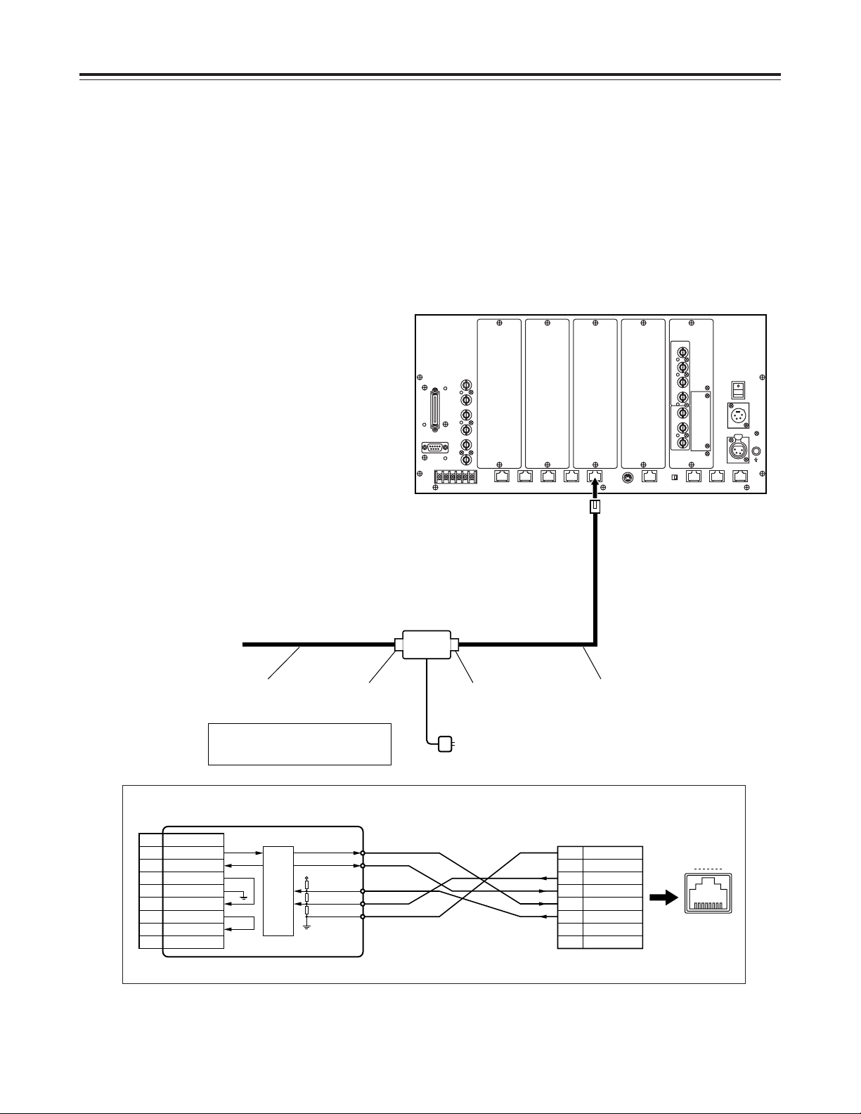
18
Connections
When using a pan-tilt head other than the
AW-PH350
When the AW-PH300, AW-PH300A, AW-PH500 or AWPH600 is to be used as a pan-tilt head, the level of the
control signals from the main unit must be converted from
RS-422 to RS-232C.
Consult with your dealer concerning the RS-232C/RS-422
converter and connecting cable.
Shown below is an example of the connections performed
by the RS-232C/RS-422 converter.
1 TXD+
RS-422RS-232C
2 TXD–
3 RXD+
1 kΩ
390 Ω
1 kΩ
VCC
AD7306JR
4 RXD–
5 GND
1
2
3
4
5
6
7
8
GND
———
COLD 2
COLD 1
HOT 1
HOT 2
———
———
18
CONTROL OUT
TO PAN/TILT HEAD
1
2
3
4
5
6
7
8
———
RXD IN
TXD OUT
DTR IN
GND
DSR OUT
RTS IN
CTS OUT
9 ———
RS-232C/RS-422 converter
Pan-tilt head:
To RS-232C connector
Cable length:
Less than 10 meters
Cable length:
Less than 800 meters
RS-232C side RS-422 side
RS-232C/RS-422 converter
D-Sub (9-pin) male
Main unit:
modular connector 8-pin plug
The RS-232C cable AW-CA28T9 may
be used for the pan-tilt head AWPH300 or AW-PH300A.
O I
FUSE
FUSE
FUSE
FUSE
FUSE
FUSE
19
Connections
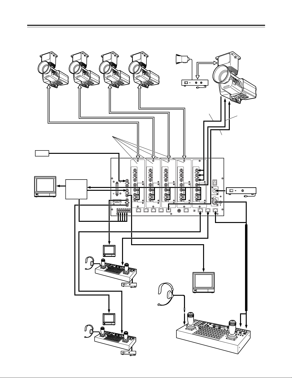
Example of system configuration
AC adapter:
AW-PS300
Main unit
Genlock signal generator
Switcher, special
effects generator,
etc.
Control panel
Remote control panel:
AW-RP615
G/L signal
VIDEO/Y
Pb
Pr
VIDEO/Y
Pb
Pr
Video board:
AW-PB605
AUX
System
tally
Inter-communications
headset
Halogen lamp Pan-tilt head system
Preview color monitor
(75 Ω terminator)
Preview color monitor
(75 Ω terminator)
Pan-tilt head system
control signal
AC adapter:
AW-PS505
AC adapter:
AW-PS505

20
Operation
$ Turning on the power
1. Set all the power switches of the connected components
and the power switch of the AC adapter to ON.
2. Set the DC POWER switch on the main unit to ON.
3. Set the OPERATE switch of the control panel to ON.
Power is now supplied to the pan-tilt head systems
connected to the main unit, and the camera’s initial
settings are performed in sequence.
<Notes>
O At the same time as the camera’s initial settings are
performed, the control panel’s PAN/TILT lever and
ZOOM lever settings are performed as well. Do not
touch the levers while the display below appears on
the LCD panel.
O It takes about 30 seconds to perform the camera’s
initial settings for each camera. The pan-tilt head
system cannot be controlled until these settings are
completed.
O All the power switches of the connected components
and the power switch of the AC adapter must be set
to ON without fail before setting the OPERATE switch
of the control panel to ON.
222
IINNIITTIIAALLIIZZEE
222
PPLLEEAASSEE WWAAIITT
$ Setting the travel range (limiters) of the
pan-tilt head
Depending on where it has been installed, there may be
obstacles within the travel range of the pan-tilt head system
with which the system may come into contact.
The pan-tilt head system may malfunction or an accident
may occur if the system comes into contact with such an
obstacle.
Prior to use, be absolutely sure to set the travel range
(limiters: upper, lower, left-most and right-most limits of
rotation) of the pan-tilt head system.
<Note>
Before installing a pan-tilt head as a stand-alone type, set
the installation direction switch inside the pan-tilt head to
stand-alone installation. (“Suspended installation” is the
factory setting.)
If this switch is not set properly, the operating directions of
the pan-tilt head will be reversed, and the limits of the pantilt head’s travel range (limiters) will not be stored in the
memory properly. For details on how to set the switch, refer
to the operating instructions of the pan-tilt head.
1. Select the pan-tilt head system using the
CONTROL/PREVIEW MONITOR OUT SEL button.
2. Set the upper limit position in the travel range.
1 Operate the PAN/TILT lever on the control panel to
rotate the camera to the position which is to serve as
the upper limit position.
2 While holding down the OK button on the control
panel, press TRACING/PRESET MEMORY button
47 .
3 The setting is completed when the 41 [LIMIT ON]
button’s lamp comes on.
O To cancel the setting, press button 47 while
pressing the OK button again. When the setting is
canceled, the 50 [LIMIT OFF] button’s lamp comes
on.
3. Set the lower limit position in the travel range.
1 Operate the PAN/TILT lever on the control panel to
rotate the camera to the position which is to serve as
the lower limit position.
2 While holding down the OK button, press button 46 .
3 The setting is completed when the 41 [LIMIT ON]
button’s lamp comes on.
O To cancel the setting, press button 46 while
pressing the OK button again. When the setting is
canceled, the 50 [LIMIT OFF] button’s lamp comes
on.
21
Operation
$ Setting the video signals
In the multi-function controller, the video signals (composite
signals and component signals) which will be used must be
set.
The correct video signals cannot be obtained unless these
settings are performed.
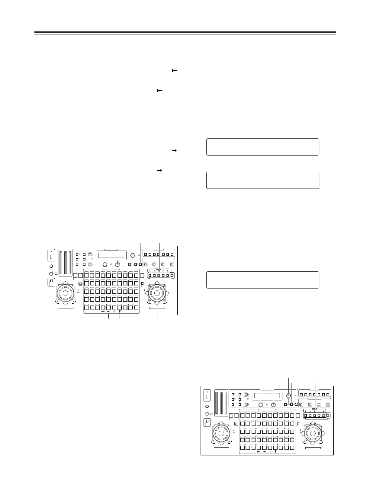
1. Select the pan-tilt head system using the
CONTROL/PREVIEW MONITOR OUT SEL button.
2. Press the MENU button, turn the menu setting control
(main), and set it so that the CONTROLLER SETTING
item appears at the top of the LCD panel.
3. Press the OK button.
The following item appears on the LCD panel.
This menu shows that input sinal is composite signal and
output signal is composite signal.
4. Turn the menu setting control (L), and set the video input
signals (displayed at the bottom left on the LCD panel).
Composite signals : C.VIDEO
Component signals : Y/Pr/Pb
<Note>
When component signals are used as the video input
signals, the RGB card (AW-PB302) available as an
optional accessory must be installed in the convertible
camera.
5. Turn the menu setting control (R), and set the video
output signals (displayed at the bottom right on the LCD
panel).
<Note>
It is not possible to set component signals (Y/Pr/Pb) for
the video output signals if composite signals (C.VIDEO)
have been set as the video input signals.
6. Select the next pan-tilt head system using the
CONTROL/PREVIEW MONITOR OUT SEL button, and
continue setting the video signals to be used for each
system concerned.
SSIIGGNNAALL SSEELLEECCTT
YY//PPrr//PPbb nCC..VVIIDDEEOO
SSIIGGNNAALL SSEELLEECCTT
CC..VVIIDDEEOO nCC..VVIIDDEEOO
CCOONNTTRROOLLLLEERR SSEETTTTIINNGG
n
OOKK KKeeyy
CONTROL/PREVIEW MONITOR OUT SEL
AUX12345
TALLY
TRACING MEMORY
LAMP
MENU
LIMIT
OFF
LIMIT
ON
FULLEMPTY
OK
LCD
CONTRAST
CAMERA
CONTROL
START
POINT
R/B
GAIN/PED
WHITE
BAL
AWC
GAIN
MODE
CLOSE
WIDE NEAR
DATA SET
TR/PSET M.LOCK
MEMORY
IRIS
IRIS
IRIS
OPEN
ZOOM
TELE
FOCUS
FAR
CALL
INCOM
LEVEL
FOCUS
OPEN
FAR
TELE
OFF
ON
OPERATE
WIDE
ZOOM/FOCUS/IRIS
ABC
ATW
A
B
NG
OK
START/STOP RESTORE RESET
DEF WIP H/F EXT ND
OPTION
PAN/TILT SET
CAMERA CONTROL
TRACING/PRESET MEMORY
IRIS
SPEED
PRIORITY
FOCUS
BAR
CAM
TR
PSET
LOW
HIGH
AUTO
MANU
AUTO
MANU
LOCK
1 2 3 4 5 6 7 8 9 10
11 12 13 14 15 16 17 18 19 20
21 22 23 24 25 26 27 28 29 130
31 32 33 34 35 36 37 38 39 40
41 42 43 44 45 46 47 48 49 50
DOWN
PAN/TILT/FOCUS/IRIS
UP
LR
CLOSE
NEAR
OPEN
FAR
CLOSE
NEAR
2•3•4•5
2•3•4•52345
1
CONTROL/PREVIEW MONITOR OUT SEL
AUX12345
TALLY
TRACING MEMORY
LAMP
MENU
LIMIT
OFF
LIMIT
ON
FULLEMPTY
OK
LCD
CONTRAST
CAMERA
CONTROL
START
POINT
R/B
GAIN/PED
WHITE
BAL
AWC
GAIN
MODE
CLOSE
WIDE NEAR
DATA SET
TR/PSET M.LOCK
MEMORY
IRIS
IRIS
IRIS
OPEN
ZOOM
TELE
FOCUS
FAR
CALL
INCOM
LEVEL
FOCUS
OPEN
FAR
TELE
OFF
ON
OPERATE
WIDE
ZOOM/FOCUS/IRIS
ABC
ATW
A
B
NG
OK
START/STOP RESTORE RESET
DEF WIP H/F EXT ND
OPTION
PAN/TILT SET
CAMERA CONTROL
TRACING/PRESET MEMORY
IRIS
SPEED
PRIORITY
FOCUS
BAR
CAM
TR
PSET
LOW
HIGH
AUTO
MANU
AUTO
MANU
LOCK
1 2 3 4 5 6 7 8 9 10
11 12 13 14 15 16 17 18 19 20
21 22 23 24 25 26 27 28 29 130
31 32 33 34 35 36 37 38 39 40
41 42 43 44 45 46 47 48 49 50
DOWN
PAN/TILT/FOCUS/IRIS
UP
LR
CLOSE
NEAR
OPEN
FAR
CLOSE
NEAR
24 5 3
2
1
4. Set the left-most limit position in the travel range.
1 Operate the PAN/TILT lever on the control panel to
rotate the camera to the position which is to serve as
the left-most limit position.
2
While holding down the OK button, press button 44 .
3 The setting is completed when the 41 [LIMIT ON]
button’s lamp comes on.
O To cancel the setting, press button 44 while
pressing the OK button again. When the setting is
canceled, the 50 [LIMIT OFF] button’s lamp comes
on.
5. Set the right-most limit position in the travel range.
1 Operate the PAN/TILT lever on the control panel to
rotate the camera to the position which is to serve as
the right-most limit position.
2
While holding down the OK button, press button 45 .
3 The setting is completed when the 41 [LIMIT ON]
button’s lamp comes on.
O To cancel the setting, press button 45 while
pressing the OK button again. When the setting is
canceled, the 50 [LIMIT OFF] button’s lamp comes
on.
6. Select the next pan-tilt head system using the
CONTROL/PREVIEW MONITOR OUT SEL button, and
continue setting the travel range (limiters) for each
system concerned.
22
Operation
$ Video signal cable compensation
Signal deterioration caused by the length of the cables from
the pan-tilt head to the main unit is compensated for.
When the length of the cables from the pan-tilt head to the
main unit exceeds 500 meters, set the cable compensation
switch inside the pan-tilt head to ON.
For further details, refer to the operating instructions of the
pan-tilt head.
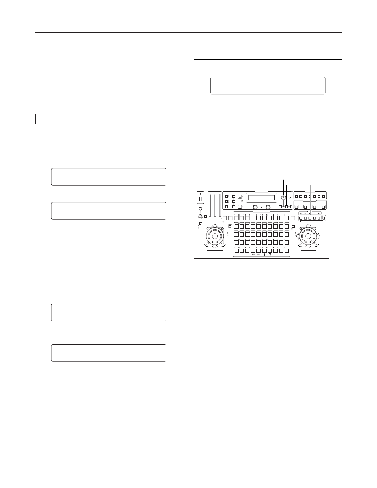
1. Select the pan-tilt head system using the
CONTROL/PREVIEW MONITOR OUT SEL button.
2. Press the MENU button, turn the menu setting control
(main), and set it so that the CABLE COMP item
appears at the top of the LCD panel.
3. Press the OK button.
The following item appears on the LCD panel.
4. Press the OK button.
The adjustment of the cable compensation for the
currently selected pan-tilt head system commences, and
the OK button’s lamp flashes.
If composite signals have been set as the video input
signals, the output signals from the convertible camera
are switched to color bar signals, and automatic
adjustment is performed.
Alternatively, if component signals have been set as the
video input signals, the output signals from the
convertible camera are switched to color bar signals of
Y/C signals, and automatic adjustment is performed.
5. Upon completion of the adjustment, the OK button’s
lamp goes off. The following item appears on the LCD
panel.
6. Select the next pan-tilt head system using the
CONTROL/PREVIEW MONITOR OUT SEL button, and
continue adjusting the cable compensation for each
system concerned.
<Note>
A small error may arise in the automatic adjustment. If
precise adjustment is required, perform the adjustment
manually. (Refer to the following page.)
CCAABBLLEE CCOOMMPP AAUUTTOO
AADDJJUUSSTT OOKK
CCAABBLLEE CCOOMMPP AAUUTTOO
AAUUTTOO AADDJJUUSSTT
CCAABBLLEE CCOOMMPP AAUUTTOO
SSTTAARRTT?? nOOKK KKeeyy
CCAABBLLEE CCOOMMPP
n
OOKK KKeeyy
Automatically adjusting the cable compensation
CONTROL/PREVIEW MONITOR OUT SEL
AUX12345
TALLY
TRACING MEMORY
LAMP
MENU
LIMIT
OFF
LIMIT
ON
FULLEMPTY
OK
LCD
CONTRAST
CAMERA
CONTROL
START
POINT
R/B
GAIN/PED
WHITE
BAL
AWC
GAIN
MODE
CLOSE
WIDE NEAR
DATA SET
TR/PSET M.LOCK
MEMORY
IRIS
IRIS
IRIS
OPEN
ZOOM
TELE
FOCUS
FAR
CALL
INCOM
LEVEL
FOCUS
OPEN
FAR
TELE
OFF
ON
OPERATE
WIDE
ZOOM/FOCUS/IRIS
ABC
ATW
A
B
NG
OK
START/STOP RESTORE RESET
DEF WIP H/F EXT ND
OPTION
PAN/TILT SET
CAMERA CONTROL
TRACING/PRESET MEMORY
IRIS
SPEED
PRIORITY
FOCUS
BAR
CAM
TR
PSET
LOW
HIGH
AUTO
MANU
AUTO
MANU
LOCK
1 2 3 4 5 6 7 8 9 10
11 12 13 14 15 16 17 18 19 20
21 22 23 24 25 26 27 28 29 130
31 32 33 34 35 36 37 38 39 40
41 42 43 44 45 46 47 48 49 50
DOWN
PAN/TILT/FOCUS/IRIS
UP
LR
CLOSE
NEAR
OPEN
FAR
CLOSE
NEAR
2
2 3•4
1
If the automatic adjustment was not performed properly,
the following item appears on the LCD panel.
Check the connection of the output signals from the
convertible camera and cables, and proceed with the
automatic adjustment again.
If the automatic adjustment was not performed properly
again even by following the automatic adjustment
procedure, perform the adjustment manually instead.
Consult your dealer if the adjustment still cannot be
performed properly even when the manual procedure is
followed.
CCAABBLLEE CCOOMMPP AAUUTTOO
AADDJJUUSSTT NNGG
23
100
IRE
90
80
70
60
50
40
30
20
10
0
–10
–20
+20
+77
–20
+20
–20
–30
–40
100
IRE
90
80
70
60
50
40
30
20
10
0
–10
–20
+20
+100
– I
75 %
100 %
75 %
100 %
1 V [p-p]1 V [p-p]
+ Q
–20
+20
–20
–30
–40
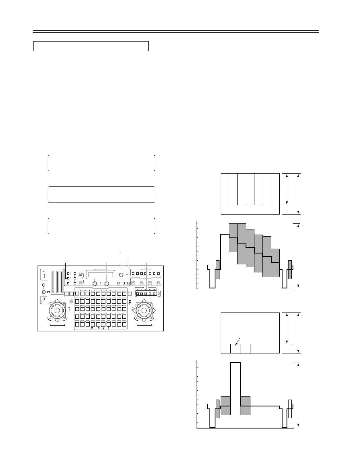
Operation
When composite signals are used
1. Select the pan-tilt head system using the
CONTROL/PREVIEW MONITOR OUT SEL button.
2. Connect a waveform monitor to the VIDEO/Y OUT
connector on the main unit corresponding to the pan-tilt
head system currently selected.
3. Press the MODE button to establish the BAR mode and
switch the output signals from the convertible camera to
color bar signals.
4. Press the MENU button, turn the menu setting control
(main), and set it so that the CABLE COMP item
appears at the top of the LCD panel.
5. Press the OK button.
The following item appears on the LCD panel.
6. Turn the menu setting control (main), and set it so that
the following item appears on the LCD panel.
CCAABBLLEE CCOOMMPP MMAANNUUAALL
YY::00 CC::00
CCAABBLLEE CCOOMMPP AAUUTTOO
SSTTAARRTT?? nOOKK KKeeyy
CCAABBLLEE CCOOMMPP
n
OOKK KKeeyy
Adjusting the cable compensation manually
7. Adjust the luminance signal using the menu setting
control (L) and the chrominance signal using the menu
setting control (R).
Adjust the luminance and chrominance signals several
times to the signal waveforms shown below.
<Note>
In the luminance and chrominance signal adjustments
performed by the multi-function controller, the level
cannot be reduced below the level of the input signals
from the camera.
It may not be possible to perform these adjustments if
the length of the cables from the pan-tilt heads to the
main unit of the multi-function controller are too short.
8. Select the next pan-tilt head system using the
CONTROL/PREVIEW MONITOR OUT SEL button, and
continue adjusting the cable compensation in each
system concerned.
Gray
Yellow
Cyan
Green
Magenta
Red
Blue
White
Black
CONTROL/PREVIEW MONITOR OUT SEL
AUX12345
TALLY
TRACING MEMORY
LAMP
MENU
LIMIT
OFF
LIMIT
ON
FULLEMPTY
OK
LCD
CONTRAST
CAMERA
CONTROL
START
POINT
R/B
GAIN/PED
WHITE
BAL
AWC
GAIN
MODE
CLOSE
WIDE NEAR
DATA SET
TR/PSET M.LOCK
MEMORY
IRIS
IRIS
IRIS
OPEN
ZOOM
TELE
FOCUS
FAR
CALL
INCOM
LEVEL
FOCUS
OPEN
FAR
TELE
OFF
ON
OPERATE
WIDE
ZOOM/FOCUS/IRIS
ABC
ATW
A
B
NG
OK
START/STOP RESTORE RESET
DEF WIP H/F EXT ND
OPTION
PAN/TILT SET
CAMERA CONTROL
TRACING/PRESET MEMORY
IRIS
SPEED
PRIORITY
FOCUS
BAR
CAM
TR
PSET
LOW
HIGH
AUTO
MANU
AUTO
MANU
LOCK
1 2 3 4 5 6 7 8 9 10
11 12 13 14 15 16 17 18 19 20
21 22 23 24 25 26 27 28 29 130
31 32 33 34 35 36 37 38 39 40
41 42 43 44 45 46 47 48 49 50
DOWN
PAN/TILT/FOCUS/IRIS
UP
LR
CLOSE
NEAR
OPEN
FAR
CLOSE
NEAR
47•103
4•6•9
5
1
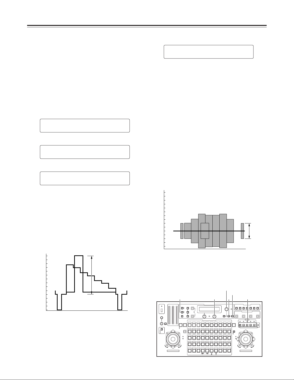
9. Turn the menu setting control (main), and set it so that
the following item appears on the LCD panel.
<Note>
When component signals have been set as the video
input signals, the output signals from the convertible
camera will be switched to Y/C signals, and
chrominance signals will be output from the Pr OUT
connector. When another item on the menu is selected,
the output signals will be switched to the component
signals.
10. Adjust the frequency response using the menu setting
control (R) in such a way that the burst level appearing
on the waveform monitor is set to 40 IRE (0.286V).
Repeatedly adjust the luminance signal and frequency
response until the signal waveforms shown below are
matched.
<Note>
In the luminance and chrominance signal adjustments
performed by the multi-function controller, the level
cannot be reduced below the level of the input signals
from the camera.
It may not be possible to perform these adjustments if
the length of the cables from the pan-tilt heads to the
main unit of the multi-function controller is too short.
CCAABBLLEE CCOOMMPP MMAANNUUAALL
ff RReessppoonnssee :: 00
24
Operation
When component signals are used
1. Select the pan-tilt head system using the
CONTROL/PREVIEW MONITOR OUT SEL button.
2. Connect a waveform monitor to the VIDEO/Y OUT
connector on the main unit corresponding to the pan-tilt
head system currently selected.
3. Press the MODE button to establish the BAR mode and
switch the output signals from the convertible camera to
color bar signals.
4. Press the MENU button, turn the menu setting control
(main), and set it so that the CABLE COMP item
appears at the top of the LCD panel.
5. Press the OK button.
The following item appears on the LCD panel.
6. Turn the menu setting control (main), and set it so that
the following item appears on the LCD panel.
<Note>
When composite signals have been set as the video
output signals, the video output signals will be switched
to component signals.
When another item on the menu is selected, the output
signals will be switched to the composite signals.
7. Adjust the luminance signal using the menu setting
control (R) in such a way that the level of the white area
appearing on the waveform monitor is set to 100 IRE
(0.714V).
CCAABBLLEE CCOOMMPP MMAANNUUAALL
YY LLeevveell :: 00
CCAABBLLEE CCOOMMPP AAUUTTOO
SSTTAARRTT?? nOOKK KKeeyy
CCAABBLLEE CCOOMMPP
n
OOKK KKeeyy
11. Select the next pan-tilt head system using the
CONTROL/PREVIEW MONITOR OUT SEL button, and
continue adjusting the cable compensation in each
system concerned.
100
IRE
90
80
70
60
50
40
30
20
10
0
–10
–20
–30
–40
+100
+7.5
100 IRE
(0.714 V)
Waveform monitor
CONTROL/PREVIEW MONITOR OUT SEL
AUX12345
TALLY
TRACING MEMORY
LAMP
MENU
LIMIT
OFF
LIMIT
ON
FULLEMPTY
OK
LCD
CONTRAST
CAMERA
CONTROL
START
POINT
R/B
GAIN/PED
WHITE
BAL
AWC
GAIN
MODE
CLOSE
WIDE NEAR
DATA SET
TR/PSET M.LOCK
MEMORY
IRIS
IRIS
IRIS
OPEN
ZOOM
TELE
FOCUS
FAR
CALL
INCOM
LEVEL
FOCUS
OPEN
FAR
TELE
OFF
ON
OPERATE
WIDE
ZOOM/FOCUS/IRIS
ABC
ATW
A
B
NG
OK
START/STOP RESTORE RESET
DEF WIP H/F EXT ND
OPTION
PAN/TILT SET
CAMERA CONTROL
TRACING/PRESET MEMORY
IRIS
SPEED
PRIORITY
FOCUS
BAR
CAM
TR
PSET
LOW
HIGH
AUTO
MANU
AUTO
MANU
LOCK
1 2 3 4 5 6 7 8 9 10
11 12 13 14 15 16 17 18 19 20
21 22 23 24 25 26 27 28 29 130
31 32 33 34 35 36 37 38 39 40
41 42 43 44 45 46 47 48 49 50
DOWN
PAN/TILT/FOCUS/IRIS
UP
LR
CLOSE
NEAR
OPEN
FAR
CLOSE
NEAR
47•103
4•6•9
5
1
100
IRE
90
80
70
60
50
40
30
20
10
0
–10
–20
+20
–20
+20
–20
–30
–40
40 IRE
(0.286 V)
Waveform monitor
8. Connect the VIDEO/Y OUT connector on the main unit
to the external reference input connector on the
waveform monitor, and connect the Pr OUT connector
on the main unit to the video signal input connector on
the waveform monitor.
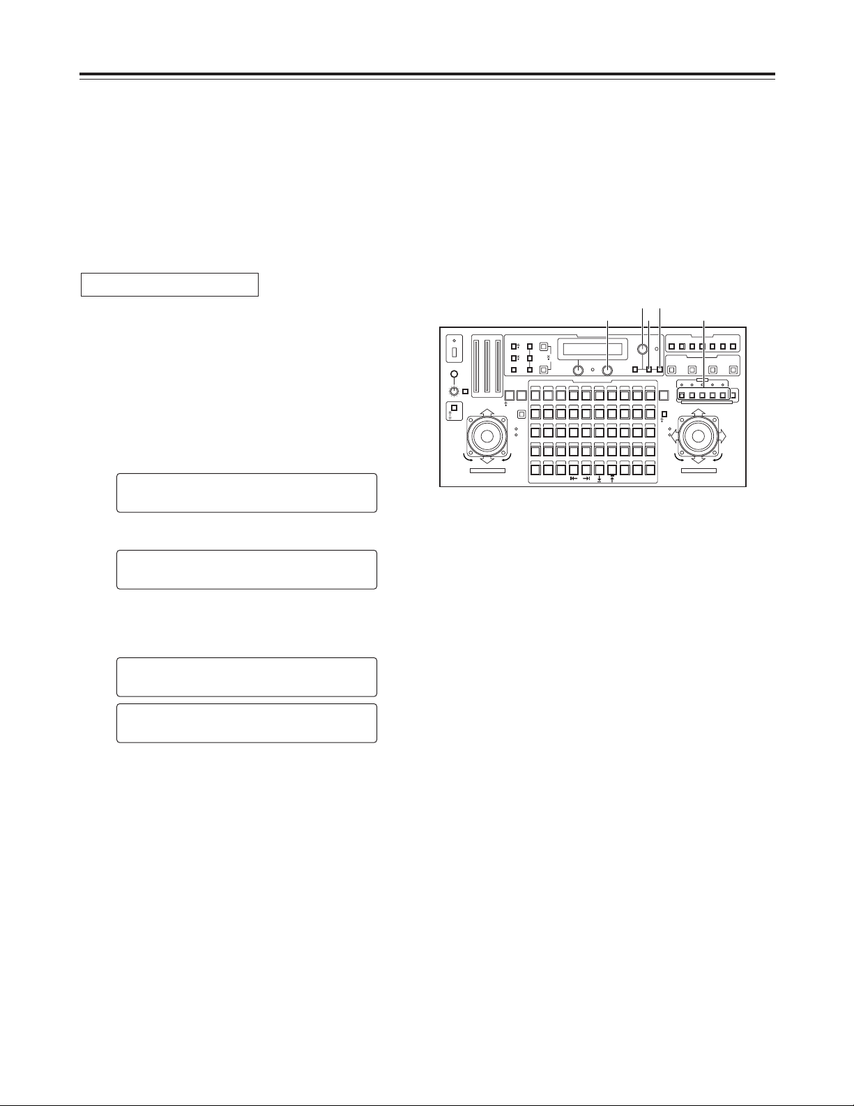
25
Operation
$ Genlock adjustment
If a camera is to be synchronized with an external signal for
use, genlock adjustment must be performed for the camera
and other equipments.
Either the black burst or VBS (video, burst and sync) signal
is used for the external sync signal.
There is no need to perform the genlock adjustment if the
camera is not going to be synchronized with an external
signal.
Adjust the genlock signal phase to match the length of the
genlock signal cable which connects the G/L OUT connector
on the main unit with the G/L IN connector on the pan-tilt
head system.
1. Select the pan-tilt head system using the
CONTROL/PREVIEW MONITOR OUT SEL button.
2. Press the MENU button, turn the menu setting control
(main), and set it so that the G/L SETTING item appears
at the top of the LCD panel.
3. Press the OK button.
The following item appears on the LCD panel.
4. Set the length of the genlock signal cable using the
menu setting control (R).
Under 500 meters : SHORT
More than 500 meters : LONG
<Note>
When SHORT has been selected for the cable length,
signals with the same phase as the genlock signal which
is supplied to the main unit are sent to the pan-tilt head
system.
Alternatively, when LONG has been selected, the phase
for the genlock signal which is supplied to the main unit
is adjusted before the signal is sent to the pan-tilt head
system.
5. Select the next pan-tilt head system using the
CONTROL/PREVIEW MONITOR OUT SEL button, and
continue setting the cable length for each system
concerned.
CCAABBLLEE LLEENNGGTTHH
LLOONNGG
CCAABBLLEE LLEENNGGTTHH
SSHHOORRTT
CCAABBLLEE LLEENNGGTTHH
SSHHOORRTT
GG//LL SSEETTTTIINNGG
n
OOKK KKeeyy
Cable length compensation
CONTROL/PREVIEW MONITOR OUT SEL
AUX12345
TALLY
TRACING MEMORY
LAMP
MENU
LIMIT
OFF
LIMIT
ON
FULLEMPTY
OK
LCD
CONTRAST
CAMERA
CONTROL
START
POINT
R/B
GAIN/PED
WHITE
BAL
AWC
GAIN
MODE
CLOSE
WIDE NEAR
DATA SET
TR/PSET M.LOCK
MEMORY
IRIS
IRIS
IRIS
OPEN
ZOOM
TELE
FOCUS
FAR
CALL
INCOM
LEVEL
FOCUS
OPEN
FAR
TELE
OFF
ON
OPERATE
WIDE
ZOOM/FOCUS/IRIS
ABC
ATW
A
B
NG
OK
START/STOP RESTORE RESET
DEF WIP H/F EXT ND
OPTION
PAN/TILT SET
CAMERA CONTROL
TRACING/PRESET MEMORY
IRIS
SPEED
PRIORITY
FOCUS
BAR
CAM
TR
PSET
LOW
HIGH
AUTO
MANU
AUTO
MANU
LOCK
1 2 3 4 5 6 7 8 9 10
11 12 13 14 15 16 17 18 19 20
21 22 23 24 25 26 27 28 29 130
31 32 33 34 35 36 37 38 39 40
41 42 43 44 45 46 47 48 49 50
DOWN
PAN/TILT/FOCUS/IRIS
UP
LR
CLOSE
NEAR
OPEN
FAR
CLOSE
NEAR
24
2 3
1
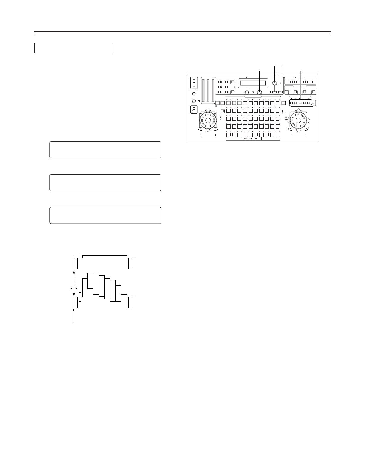
26
Operation
1. Select the pan-tilt head system using the
CONTROL/PREVIEW MONITOR OUT SEL button.
2. Supply the genlock signal to the G/L IN connector on the
main unit, and connect a dual-trace oscilloscope to the
loop-through connector and VIDEO/Y OUT connector on
the main unit corresponding to the pan-tilt head system
currently selected.
3. Press the MENU button, turn the menu setting control
(main), and set it so that the G/L SETTING item appears
at the top of the LCD panel.
4. Press the OK button.
The following item appears on the LCD panel.
5. Turn the menu setting control (main), and set it so that
the following item appears on the LCD panel.
6. Using the menu setting control (R), align the horizontal
phase of the video signal waveforms on the oscilloscope
and external sync signal waveforms.
HH PPHHAASSEE
±±00
CCAABBLLEE LLEENNGGTTHH
SSHHOORRTT
GG//LL SSEETTTTIINNGG
n
OOKK KKeeyy
Horizontal phase adjustment
External sync
signal
Video signal
Align the horizontal phase.
7. Select the next pan-tilt head system using the
CONTROL/PREVIEW MONITOR OUT SEL button, and
continue adjusting the horizontal phase in each system
concerned.
CONTROL/PREVIEW MONITOR OUT SEL
AUX12345
TALLY
TRACING MEMORY
LAMP
MENU
LIMIT
OFF
LIMIT
ON
FULLEMPTY
OK
LCD
CONTRAST
CAMERA
CONTROL
START
POINT
R/B
GAIN/PED
WHITE
BAL
AWC
GAIN
MODE
CLOSE
WIDE NEAR
DATA SET
TR/PSET M.LOCK
MEMORY
IRIS
IRIS
IRIS
OPEN
ZOOM
TELE
FOCUS
FAR
CALL
INCOM
LEVEL
FOCUS
OPEN
FAR
TELE
OFF
ON
OPERATE
WIDE
ZOOM/FOCUS/IRIS
ABC
ATW
A
B
NG
OK
START/STOP RESTORE RESET
DEF WIP H/F EXT ND
OPTION
PAN/TILT SET
CAMERA CONTROL
TRACING/PRESET MEMORY
IRIS
SPEED
PRIORITY
FOCUS
BAR
CAM
TR
PSET
LOW
HIGH
AUTO
MANU
AUTO
MANU
LOCK
1 2 3 4 5 6 7 8 9 10
11 12 13 14 15 16 17 18 19 20
21 22 23 24 25 26 27 28 29 130
31 32 33 34 35 36 37 38 39 40
41 42 43 44 45 46 47 48 49 50
DOWN
PAN/TILT/FOCUS/IRIS
UP
LR
CLOSE
NEAR
OPEN
FAR
CLOSE
NEAR
36
3•5 4
1
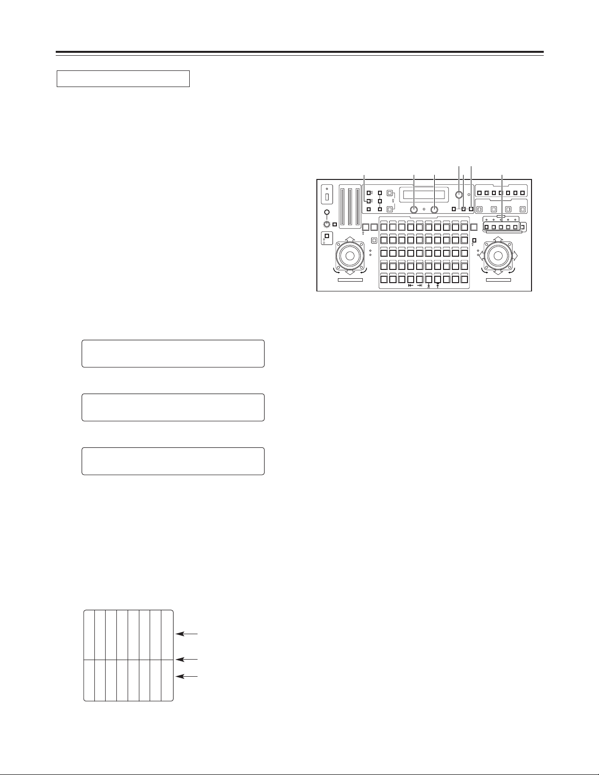
27
Operation
The subcarrier phase adjustment must be performed, when
composite signals have been set as the video input signals
and the pictures are to be switched by a video switcher or
other equipments.
This adjustment is not necessary when component signals
have been set as the video input signals.
1. Select the pan-tilt head system using the
CONTROL/PREVIEW MONITOR OUT SEL button.
2. Connect the video switcher or other equipments to the
VIDEO/Y OUT connector on the main unit that
corresponds to the currently selected pan-tilt head
system, and connect a color monitor to the video output
connector on the video switcher or other equipments.
3. Press the MODE button to establish the BAR mode and
switch the output signals from the convertible camera to
color bar signals.
4. Press the MENU button, turn the menu setting control
(main), and set it so that the G/L SETTING item appears
at the top of the LCD panel.
5. Press the OK button.
The following item appears on the LCD panel.
6. Turn the menu setting control (main), and set it so that
the following item appears on the LCD panel.
7. Output both the color bar signals (signals from inside the
switcher or other equipments) serving as the reference
and the color bar signals from the camera to the color
monitor.
8. Align the phase of the color bar signals from the camera
with the phase of the color bar signals serving as the
reference.
Use the menu setting control (L) to adjust the phase in
90-degree increments and then the menu setting control
(R) to make fine adjustments.
SSCC PPHHAASSEE
CCOOAARRSSEE::11 FFIINNEE:: ±±00
CCAABBLLEE LLEENNGGTTHH
SSHHOORRTT
GG//LL SSEETTTTIINNGG
n
OOKK KKeeyy
Subcarrier phase adjustment
White
Yellow
Cyan
Green
Magenta
Red
Blue
Black
Color bar signals from the
camera
Partition line
Color bar signals from the
switcher or other
equipments
9. Select the next pan-tilt head system using the
CONTROL/PREVIEW MONITOR OUT SEL button, and
continue adjusting the subcarrier phase in each system
concerned.
CONTROL/PREVIEW MONITOR OUT SEL
AUX12345
TALLY
TRACING MEMORY
LAMP
MENU
LIMIT
OFF
LIMIT
ON
FULLEMPTY
OK
LCD
CONTRAST
CAMERA
CONTROL
START
POINT
R/B
GAIN/PED
WHITE
BAL
AWC
GAIN
MODE
CLOSE
WIDE NEAR
DATA SET
TR/PSET M.LOCK
MEMORY
IRIS
IRIS
IRIS
OPEN
ZOOM
TELE
FOCUS
FAR
CALL
INCOM
LEVEL
FOCUS
OPEN
FAR
TELE
OFF
ON
OPERATE
WIDE
ZOOM/FOCUS/IRIS
ABC
ATW
A
B
NG
OK
START/STOP RESTORE RESET
DEF WIP H/F EXT ND
OPTION
PAN/TILT SET
CAMERA CONTROL
TRACING/PRESET MEMORY
IRIS
SPEED
PRIORITY
FOCUS
BAR
CAM
TR
PSET
LOW
HIGH
AUTO
MANU
AUTO
MANU
LOCK
1 2 3 4 5 6 7 8 9 10
11 12 13 14 15 16 17 18 19 20
21 22 23 24 25 26 27 28 29 130
31 32 33 34 35 36 37 38 39 40
41 42 43 44 45 46 47 48 49 50
DOWN
PAN/TILT/FOCUS/IRIS
UP
LR
CLOSE
NEAR
OPEN
FAR
CLOSE
NEAR
4883
4•6 5
1
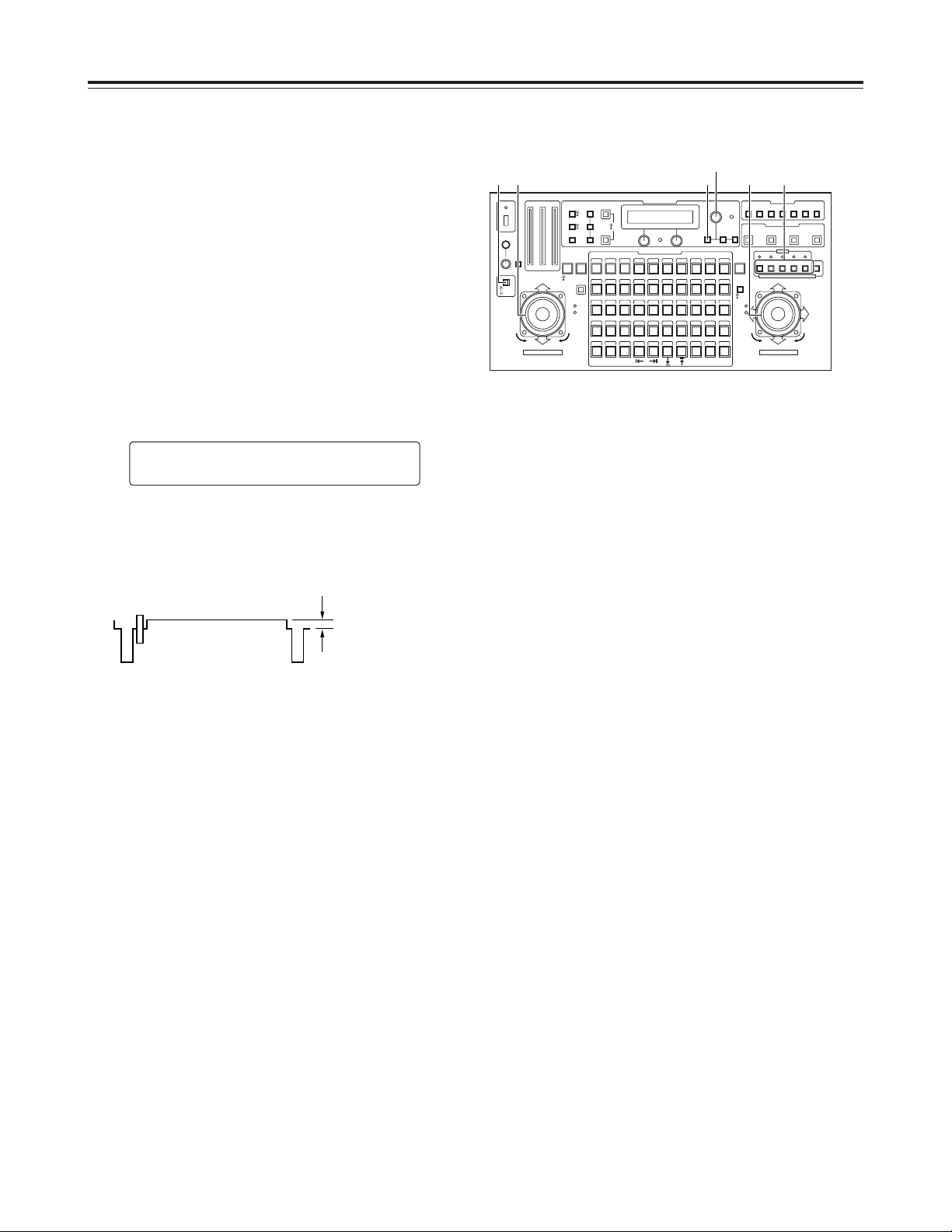
28
Operation
$ Total pedestal adjustment
When more than one camera is to be used, the black level
(pedestal level) of the pictures shot by each of the cameras
must be brought into alignment.
1. Select the pan-tilt head system using the
CONTROL/PREVIEW MONITOR OUT SEL button.
2. Connect a waveform monitor to the VIDEO/Y OUT
connector on the main unit that corresponds to the pantilt head system currently selected.
3. Press the IRIS button to establish the MANU mode (the
IRIS button’s lamp now goes off), and use the
FOCUS/IRIS dial to close the lens iris.
4. Press the R/B GAIN/PED button, and set it so that the
following item appears on the LCD panel.
5. Use the menu setting control (main) to adjust the black
level to 5 IRE (0.035V) or 7.5 IRE (0.050V).
<Note>
The black level should be adjusted to the same level of
equipments of the system.
PPEEDDEESSTTAALL TTOOTTAALL ±±00
RR:: ±±00 BB:: ±±00
6. Select the next pan-tilt head system using the
CONTROL/PREVIEW MONITOR OUT SEL button, and
continue adjusting the black level for each system
concerned.
5 IRE (0.035V)
or
7.5 IRE (0.050V)
CONTROL/PREVIEW MONITOR OUT SEL
AUX12345
TALLY
TRACING MEMORY
LAMP
MENU
LIMIT
OFF
LIMIT
ON
FULLEMPTY
OK
LCD
CONTRAST
CAMERA
CONTROL
START
POINT
R/B
GAIN/PED
WHITE
BAL
AWC
GAIN
MODE
CLOSE
WIDE NEAR
DATA SET
TR/PSET M.LOCK
MEMORY
IRIS
IRIS
IRIS
OPEN
ZOOM
TELE
FOCUS
FAR
CALL
INCOM
LEVEL
FOCUS
OPEN
FAR
TELE
OFF
ON
OPERATE
WIDE
ZOOM/FOCUS/IRIS
ABC
ATW
A
B
NG
OK
START/STOP RESTORE RESET
DEF WIP H/F EXT ND
OPTION
PAN/TILT SET
CAMERA CONTROL
TRACING/PRESET MEMORY
IRIS
SPEED
PRIORITY
FOCUS
BAR
CAM
TR
PSET
LOW
HIGH
AUTO
MANU
AUTO
MANU
LOCK
1 2 3 4 5 6 7 8 9 10
11 12 13 14 15 16 17 18 19 20
21 22 23 24 25 26 27 28 29 130
31 32 33 34 35 36 37 38 39 40
41 42 43 44 45 46 47 48 49 50
DOWN
PAN/TILT/FOCUS/IRIS
UP
LR
CLOSE
NEAR
OPEN
FAR
CLOSE
NEAR
43 3 (3)51
 Loading...