

Panasonic AW-RP50, AW-RM50 Quick Start Manual
1. Connect AW-RP50 LAN port and AW-XXXX LAN port using a LAN cable. (AW-XXXX can
automatically recognize whether it is a cross or straight cable.)
* LAN Cable: Category 5 or higher, Up to 100m (Category 5e or higher if connected via a PoE+ compatible hub)
* Connecting AW-RP50 and AW-XXXX via a hub: Straight cable, Category 5 or higher, Up to 100m
2. Operate AW-RP50 to set up the connection with AW-XXXX.
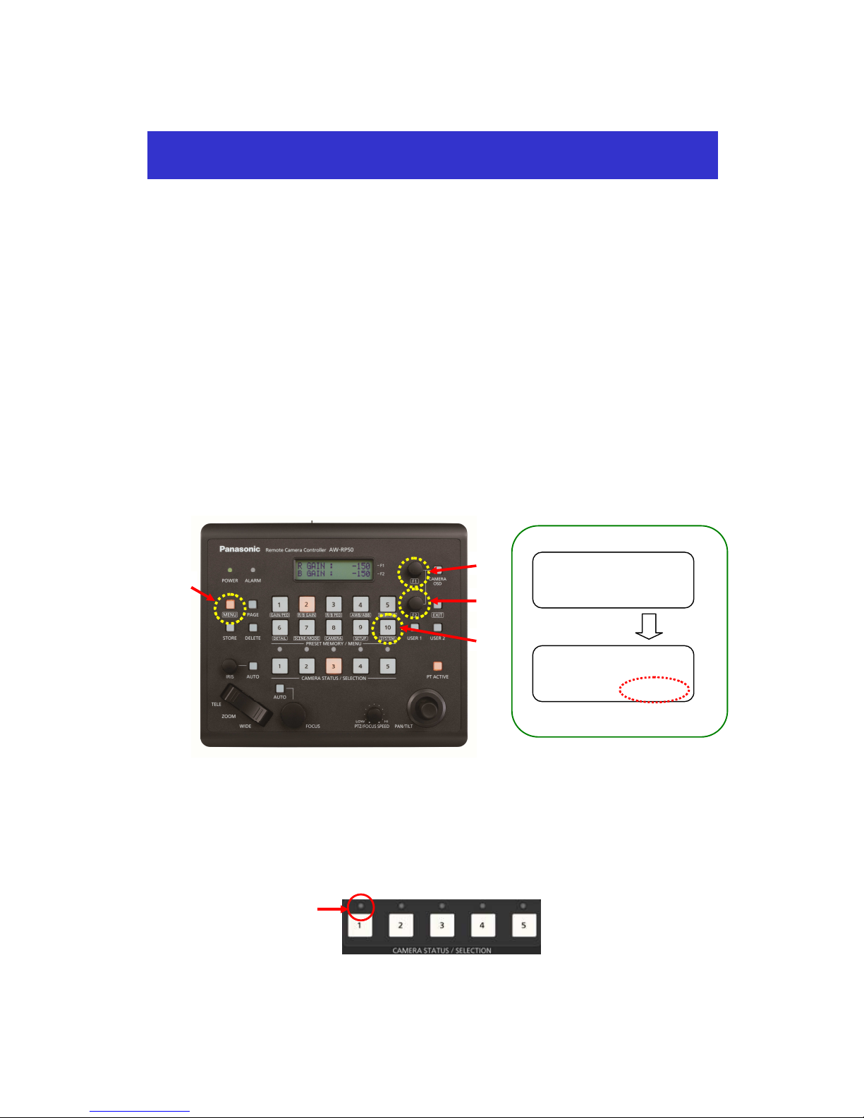
Press MENU button. - (Fig. 1-A)
Press [10] SYSTEM button. - (Fig. 1-B) * “[1] CAMERA CTL” will be displayed on the LCD screen. - (Fig. 2)
* If it is not displayed, turn F1 dial to make “[1] CAMERA CTL” appear.
While “[1] CAMERA CTL” is displayed on the LCD, press F1 dial. – (Fig. 1-C)
(“[1] CAM1” will be displayed on the upper half, and the connection method (default: [NoAsign]) on the
lower half of the LCD screen.)
* If it is not displayed, turn F1 dial to make [CAM1] appear.
④ Turn F2 dial to select [Network], then press F2 dial to determine the setting. – (Fig. 1-D)
After the setting-up is completed, LED button 1 (CAM1) in the picture below (AW-RP50 CAMERA STATUS /
SELECTION Area) lights up according to the camera’s power status. If the camera is in STANDBY mode (power
OFF: factory default), it lights up in orange. If in POWER ON mode (power ON), it lights up in green.
* When the camera is in STANBY mode, the Power-ON operation needs to be done. (Please see “3. Turn
AW-XXXX on” below.)
(AW-RP50: CAMERA STATUS/SELECTION Area)
1.CAM1
Network
[1]
CA
MERA CTL
MENU ON ⇒
Select [10]
Press F1
Turn F2 to select ⇒
Press F2 to determine
Controlling (One) PTZ Camera via AW-RP50 Controller
After setting up, this lights up
a
ccording to the camera’s
power status.
* If it does not light up, please check the following points.
(Figure 1)
(Figure 2)
(A)
(B)
(C)
(D)
① C
heck the connection state of LAN cable or whether you are using a cable that meets the specifications.
(?) Why is it possible to control the camera by this setting-up only?
Default IP address for AW-XXXX is (192.168.0.10).
Meanwhile, the camera IP address table (CAM IP ADR) /CAM1 provided for AW-RP50 in advance is set to
(192.168.0.10).
So, when the connection method for [1] CAM1 is set to [Network], AW-RP50 recognizes the camera as CAM1.
☆AW-RP50: MENU > [10] SYSTEM > [7] CAM IP ADR with default setting values
to
* When AW-XXXX with its IP address set to (192.168.0.11) is connected via IP connection, if the
Connection setting for [CAM IP ADR]/CAM2 is changed to [Network], this AW-XXXX is recognized as CAM2.
3. Turn AW-XXXX on.
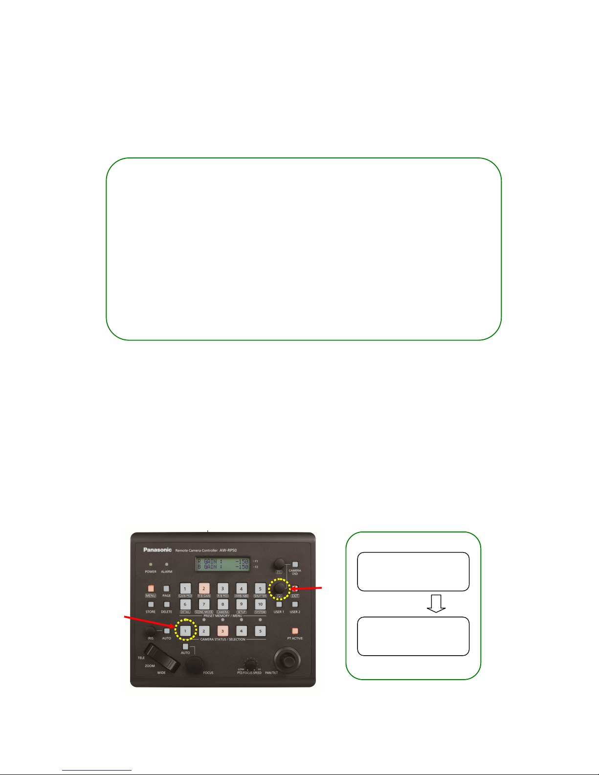
(How to switch over to POWER ON mode (power ON) on AW-XXXX connected to CAM1)
· Hold down LED button 1 at CAMERA STATUS/SELECTION. – (Fig. 3-A)
* While the button is held down, the selected camera and its power status will be displayed on the LCD
screen.
– (Fig. 4)
· Keeping the button held down, turn F2 dial to select “ON”. Then press F2 dial to determine it. – (Fig. 3-B)
* By this operation, AW-XXXX will be switched over to POWER ON mode after its default setting motion.
(The status lamp will light up in green and the LED on AW-RP50 will also light up in green.)
* When performing the same procedure from POWER ON mode, if [POWER: OFF] is selected, AW-XXXX will be
switched over to STANDBY mode.
CAM1<AW-XXXX >
POWER
:
OFF
CAM1<AW-XXXX >
POWER
:
ON
1 IP: CAM1 (192.168.0.10)
100 IP: CAM100 (192.168.0.109)
“CAM1” is held down
Select “ON” ⇒ Press F2 to determine
Turn F2
(A)
(Figure 3)
(Figure 4)
(B)
② Check that the LAN cable is connected to “LAN port”, not to “RS422 port”.
③ Double-check that there is no error in setting up the connection.
★ This is to explain how to set up the connection between 3 AW-XXXX cameras and AW-RP50
controller.
1. Connect AW-RP50 LAN port and the hub using a Category 5 or higher straight cable.
2. Connect AW-XXXX LAN port and the hub using a LAN cable. (AW-XXXX can automatically recognize
whether it is a cross or straight cable.)
* LAN Cable: Category 5 or higher, Up to 100m (Category 5e or higher if connected via a PoE+ compatible hub)
3. By [1] CAMERA CTL setting, select [No Asign] for a CAMERA No. you want to assign.
★ AW-RP50 will automatically assign IP addresses to the tables with their connection method set to [No Asign] in
ascending order of camera’s MAC address.
* MAC address of AW-XXXX can be checked using EASY IP Setup Software (*1) only.
(*1) “EASY IP Setup Software”
This software can be downloaded from CD-ROM that comes with AW-XXXX or the following website.
https://eww.pass.panasonic.co.jp/pro-av/support/content/download/JP/jp2main/soft/tool_ipset_agree_j.htm
For its basic operation, please refer to the Manual 【EASY IP Setup Software】.
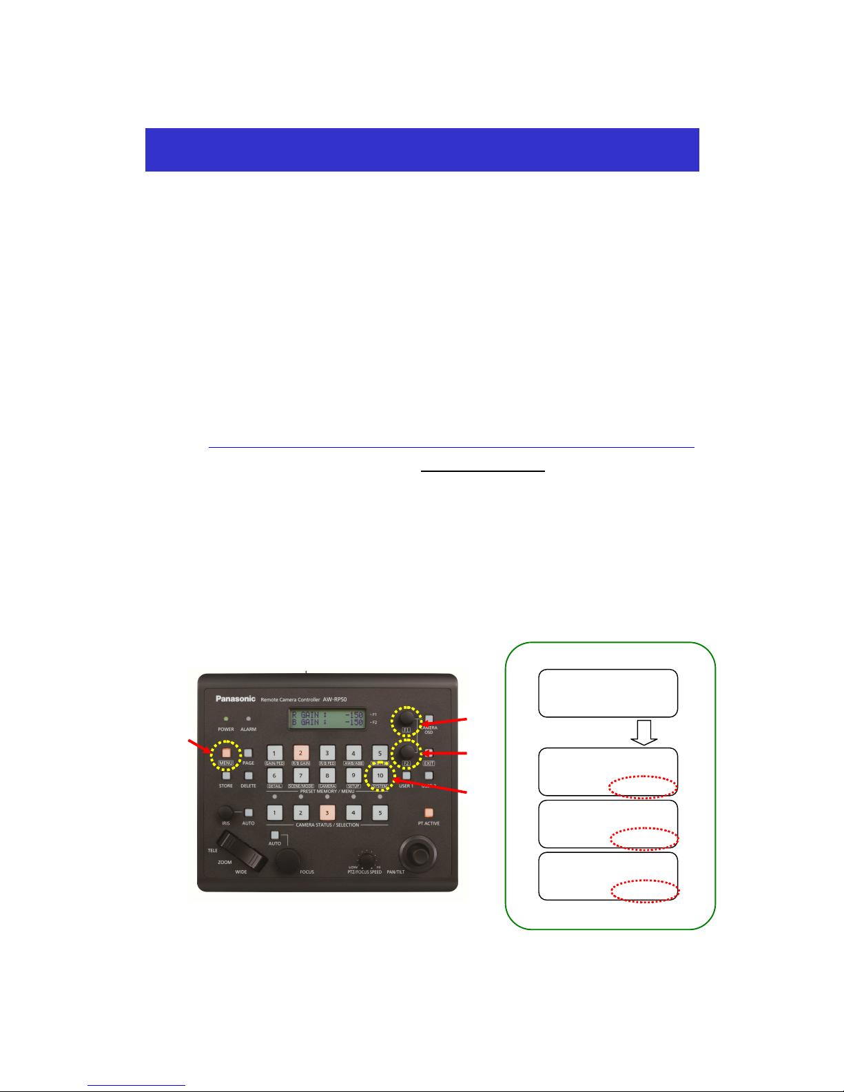
① P
ress MENU button. - (Fig. 1-A)
② Press [10] SYSTEM button. - (Fig. 1-B) * “[1] CAMERA CTL” will be displayed on the LCD screen. - (Fig. 2)
③ While “[1] CAMERA CTL” is displayed on the LCD screen, press F1 dial. – (Fig. 1-C)
④ Select CAM1, CAM2 and CAM3 using F1 dial, and select [No Asign] for each of them using F2 dial.
Then press F2 dial to determine each setting. – (Fig. 1-D)
Controlling Multiple AW-XXXX Cameras via AW-RP50 Controller
MENU ON ⇒
Select
2.CAM2
NoAsign
3.CAM3
NoAsign
Press F1
Turn F2 to select ⇒
Press F2 to determine
1.CAM1
NoAsign
[1]CAMERA CTL
(A)
(B)
(C)
(D)
(Figure 1)
(Figure 2)
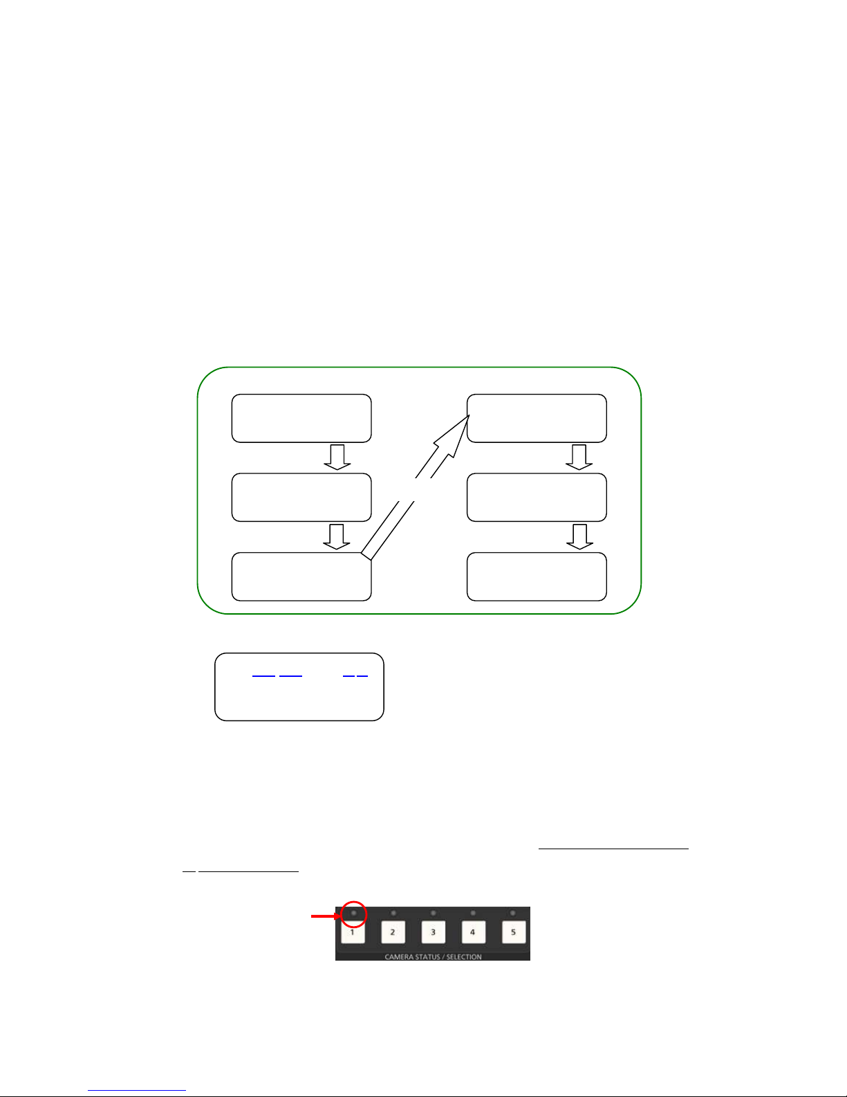
4. By [5] AUTO SET IP setting, execute the automatic assignment of IP addresses. (RENEW IP ADR)
① I
n the state of the above-mentioned 3.-②, turn F1 dial to select [5] AUTO SET IP.
② Press F1 dial to make [RENEW IP ADR] appear on the lower half of the LCD screen.
* If it does not appear, turn F2 dial to make [RENEW IP ADR] appear.
③ While [RENEW IP ADR] is displayed, press F2 dial. The number of units that AW-RP50 has newly detected
and the number of units that it currently manages (all the remote cameras and switchers) will be displayed on
the upper half of the LCD screen. (*2)
④ [NO] will be displayed on the lower half of the LCD screen. So, turn F2 dial to select [YES] and then press F2
dial.
⑤ When [COMPLETE] is displayed on the lower half of the LCD screen, the setting-up is completed.
(*
2) The cameras (C) and switchers (S) that AW-RP50 manages are displayed as follows.
After setting up, LED buttons 1 – 3 at <CAMERA STATUS / SELECTION> on the AW-RP50 operation panel light up
in a few seconds according to the camera’s power status. If a camera is in STANDBY mode (power OFF: factory
default), it lights up in orange. If in POWER ON mode (power ON), it lights up in green.
* When a camera is in STANDBY mode, the Power-ON operation needs to be done.
For this operation, please refer to “3. Turn AW-XXXX on” of the Manual 【Controlling AW-XXXX Camera
via AW-RP50 Controller】.
(AW-RP50: CAMERA STATUS/SELECTION Area)
[1]CAMERA CTL
MENU ON ⇒
Select [10]
[5]AUTO SET IP
1.AU
TO SET
RENEW
IP ADR
Turn F1
Press
C:003/003
S:
1/1
NO↓
C:003/003
S:
1/1
YES↓
C:003/003
S:
1/1
COMPLETE
Turn F2
Press F2
Press F2
② C
urrently managed cameras + ①
③ N
ewly detected switchers
④ C
urrently managed switchers + ③
① ②
③ ④
C:003/003 S:
1/1
① N
ewly detected cameras
① ② ③ ④
After setting up, this lights up
a
ccording to the camera’s
power status.
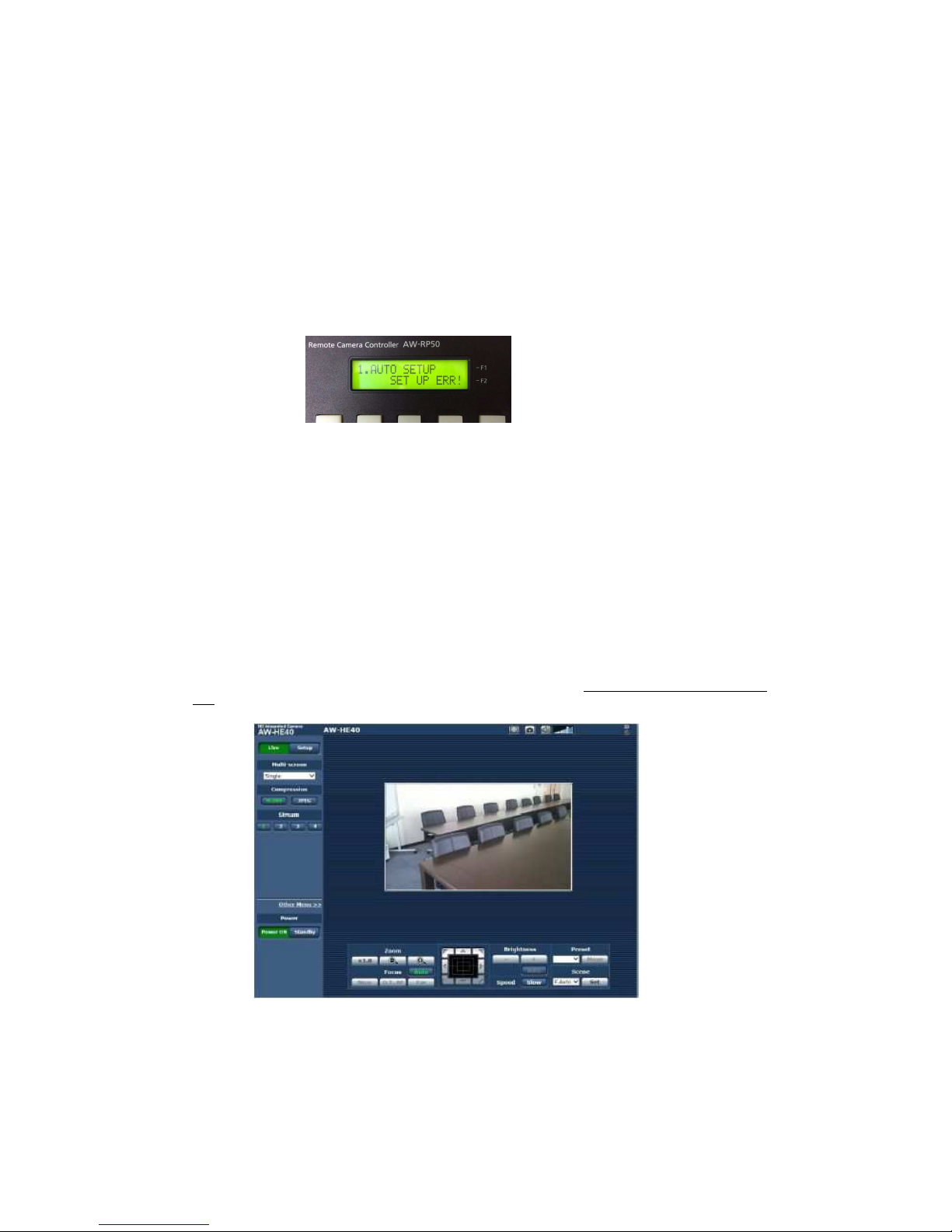
(NOTE) For security enhancement, when 20 minutes or more have passed after the power is turned on, AW-XXXX no
longer allows you to set the network-related settings. If the following message is displayed on the LCD
screen, please reboot AW-XXXX, and then set those settings.
* The length of time for which you are allowed to control the network-related settings can be changed via the MENU
setting on the Web screen.
(*1) Setting: [Easy IP Setup accommodate period] setting
- This is a setting to decide how long the control of network settings is enabled after AW-XXXX starts up
via EASY IP Setup Software or AW-RP50.
【Location】 Web Setup Screen >
Setup > Network > Easy IP Setup accommodate period
[20min]: Enables controlling the camera settings via EASY IP Setup Software, etc. for 20 minutes only after the
camera starts up. (Default)
[Unlimited]: Enables controlling the camera settings via EASY IP Setup Software, etc. all the time.
★For the connection between PC and AW-XXXX, please refer to the Manual 【Controlling AW-XXXX Camera via
PC】.
(Web Screen for AW-XXXX)
* If it does not light up, please check the following points.
① Check the connection state of LAN cable or whether you are using a cable that meets the specifications.
② Check that the LAN cable is connected to “LAN port”, not to “RS422 port”.
③ Double-check that there is no error in setting up the connection.
 Loading...