

Page 1
Before attempting to connect, operate or adjust this product,
please read these instructions completely.
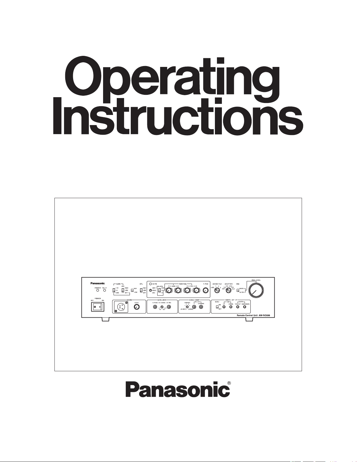
Remote Control Unit
AW-RC600P
Page 2
2
indicates safety information.
This class A digital apparatus complies with
Canadian ICES-003.
Cet appareil numérique de la classe A est
conforme à la norme NMB-003 du Canada.
For CANADA
Safety precautions
CAUTION
RISK OF ELECTRIC SHOCK
DO NOT OPEN
CAUTION: TO REDUCE THE RISK OF ELECTRIC SHOCK,
DO NOT REMOVE COVER (OR BACK).
NO USER SERVICEABLE PARTS INSIDE.
REFER TO SERVICING TO QUALIFIED SERVICE PERSONNEL.
The lightning flash with arrowhead symbol,
within an equilateral triangle, is intended to
alert the user to the presence of uninsulated
“dangerous voltage” within the product’s
enclosure that may be of sufficient magnitude
to constitute a risk of electric shock to
persons.
The exclamation point within an equilateral
triangle is intended to alert the user to the
presence of important operating and
maintenance (service) instructions in the
literature accompanying the appliance.
WARNING:
• TO REDUCE THE RISK OF FIRE OR ELECTRIC
SHOCK, DO NOT EXPOSE THIS APPARATUS TO
RAIN OR MOISTURE.
• THE APPARATUS SHALL NOT BE EXPOSED TO
DRIPPING OR SPLASHING AND THAT NO
OBJECTS FILLED WITH LIQUIDS, SUCH AS
VASES, SHALL BE PLACED ON THE
APPARATUS.
CAUTION:
TO REDUCE THE RISK OF FIRE OR SHOCK
HAZARD AND ANNOYING INTERFERENCE, USE
THE RECOMMENDED ACCESSORIES ONLY.
FCC Note:
This equipment has been tested and found to comply
with the limits for a class A digital device, pursuant to
Part 15 of the FCC Rules. These limits are designed
to provide reasonable protection against harmful
interference when the equipment is operated in a
commercial environment. This equipment generates,
uses, and can radiate radio frequency energy, and if
not installed and used in accordance with the
instruction manual, may cause harmful interference to
radio communications. Operation of this equipment in
a residential area is likely to cause harmful interference
in which case the user will be required to correct the
interference at his own expense.
Warning:
To assure continued FCC emission limit compliance,
the user must use only shielded interface cables when
connecting to external units. Also, any unauthorized
changes or modifications to this equipment could void
the user’s authority to operate it.
CAUTION:
In order to maintain adequate ventilation, do not
install or place this unit in a bookcase, built-in
cabinet or any other confined space. To prevent
risk of electric shock or fire hazard due to
overheating, ensure that curtains and any other
materials do not obstruct the ventilation.
Page 3
3
1) Read these instructions.
2) Keep these instructions.
3) Heed all warnings.
4) Follow all instructions.
5) Do not use this apparatus near water.
6) Clean only with dry cloth.
7) Do not block any ventilation openings. Install in
accordance with the manufacturer’s instructions.
8) Do not install near any heat sources such as
radiators, heat registers, stoves, or other apparatus
(including amplifiers) that produce heat.
9) Do not defeat the safety purpose of the polarized
or grounding-type plug. A polarized plug has two
blades with one wider than the other. A groundingtype plug has two blades and a third grounding
prong. The wide blade or the third prong are
provided for your safety. If the provided plug does
not fit into your outlet, consult an electrician for
replacement of the obsolete outlet.
10) Protect the power cord form being walked on
or pinched particularly at plugs, convenience
receptacles, and the point where they exit from the
apparatus.
11) Only use attachments/accessories specified by the
manufacturer.
12) Use only with the cart, stand,
tripod, bracket, or table specified
by the manufacturer, or sold with
the apparatus. When a cart is used,
use caution when moving the cart/
apparatus combination to avoid injury
from tip-over.
13) Unplug this apparatus during lightning storms or
when unused for long periods of time.
14) Refer all servicing to qualified service personnel.
Servicing is required when the apparatus has
been damaged in any way, such as power-supply
cord or plug is damaged, liquid has been spilled
or objects have fallen into the apparatus, the
apparatus has been exposed to rain or moisture,
does not operate normally, or has been dropped.
Read these operating instructions carefully before using the unit. Follow the safety instructions on the unit and the
applicable safety instructions listed below. Keep these operating instructions handy for future reference.
IMPORTANT SAFETY INSTRUCTIONS
Safety precautions
indicates safety information.
Page 4

4
This remote control unit (RCU) is designed to be used with a convertible camera (such as the AW-E860, AW-E750, AW-E650,
AW-E655 or AW-E350).
By connecting the RCU cable (AW-CA50A26), the power supply to the camera as well as the camera settings, switching
operations and adjustments can be performed by remote control.
The unit comes with a tally/intercom input/output connector, AUX input/output connector (for line viewing) and G/L input/output
connector to make it easy to configure a system.
Also provided are controller connectors for controlling a contact-type pan/tilt head and lens.
The maximum extendible length of the cables is as follows:
Camera body (including lens): 984 ft. (300 m)
AW-E860 + AW-PB305 (studio card) + 5-inch viewfinder:
328 ft. (100 m)
Cables
AW-CA50A26 RCU cable 49.2 ft. (15 m)
WV-CA26U15 Studio cable for extension
49.2 ft. (15 m)
WV-CA26U30 Studio cable for extension
98.4 ft. (30 m)
WV-CA26U100 Studio cable for extension
328 ft. (100 m)
WV-CA26T26 Joint connector for extension
Introduction .......................................................................
4
Accessories ...................................................................... 4
Precautions for use ..........................................................
5
Parts and their functions .................................................
6
Front panel ......................................................................
6
Rear panel .....................................................................
11
Connections .................................................................... 13
Operating procedure ......................................................
14
Adjustment ...................................................................... 15
Cable compensation .....................................................
15
White balance adjustments ...........................................
16
Black balance adjustments ...........................................
17
Gen-lock adjustment .....................................................
18
Menu item setting ...........................................................
19
Rack mounting ................................................................
20
Appearance ..................................................................... 21
Specifications ................................................................. 22
Power cable ......................................................................
1
Rack-mount angles .........................................................
2
Mounting screws .............................................................
4
Rack angle handles .........................................................
2
Rack angle handle fixing screws ...................................
4
Contents
Introduction
Accessories
Note
When the remote control unit is to be discarded at the end of its service life, ask a specialized contractor to dispose of
it properly in order to protect the environment.
Page 5

5
Handle the unit carefully.
Dropping the unit or subjecting it to strong impact may give rise to malfunctioning or accidents.
Operate the unit within a temperature range of 14°F (–10°C) to 113°F (+45°C).
Operation in locations below 14°F (–10°C) or above 113°F (+45°C) may adversely affect the internal parts.
Turn off the power before connecting or disconnecting the cables.
Be absolutely sure to turn off the power before connecting or disconnecting the cables.
AC 120 V is the unit’s rated supply voltage.
Be absolutely sure to supply an AC 120 V voltage to the unit.
Maintenance
Wipe the unit using a dry cloth. To remove stubborn dirt, dip a cloth into a diluted solution of kitchen detergent, wring it out
well, and wipe the unit gently.
Precautions for use
Caution
Avoid using benzine, paint thinners and other volatile fluids.
If a chemical cleaning cloth is to be used, carefully read through the precautions for its use.
Page 6
6
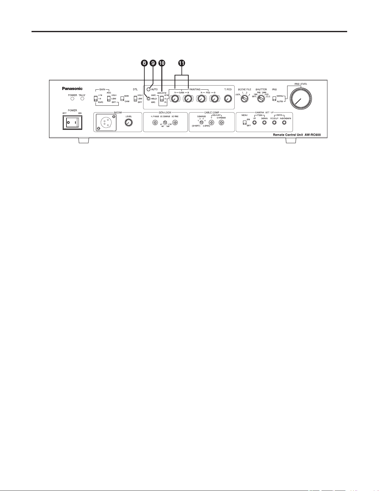
Power switch [POWER OFF/ON]
ON: At this setting, the power is supplied to the unit
(and the power indicator LED lights).
OFF: At this setting, the power is off.
Power indicator LED [POWER]
When the power switch is set to [ON], this LED lights up
green to indicate that the unit can be operated.
Tally indicator LED [TALLY]
Connect the unit’s tally/intercom input/output connector
with the TALLY & INCOM connector on the live switcher
(AW-SW350). This LED lights up red when the unit is
selected using the controls on the live switcher.
Gain increase selector switch
[GAIN +18/+9/0(dB)]
This switch is operational only when the AGC selector
switch
is at the [OFF] setting.
When the AGC selector switch
is at the [LOW] or
[HIGH] setting, the gain will remain unchanged even
when the setting of the gain increase selector switch is
switched.
The switch is normally used as the [0 dB] position. When
shooting in dark locations and a sufficient video output
cannot be obtained even by setting the lens iris to wide
open, set it to [+9 dB] or [+18 dB].
AGC selector switch [AGC HIGH/LOW/OFF]
HIGH: At this setting, the maximum AGC gain is set to
+30 dB. (This value may differ according to the
camera used.)
LOW: At this setting, the maximum AGC gain is set to
+18 dB. (This value may differ according to the
camera used.)
OFF: AGC does not function. Select the gain using the
gain increase selector switch
.
Fine adjustment of AGC
If, when this switch is at the [HIGH] or [LOW] setting, the
scene file switch
is set to [USER], [Auto iris adjust] is
set to [ON] on the camera menu and the lens iris selector
switch
is set to [AUTO], the AGC level can be finely
adjusted using the lens iris control
.
(For details on the camera menus, refer to the camera’s
operating instructions.)
Color bar/camera selector switch [BAR/CAM]
Set this switch to [BAR] to output color bar signals.
Normally, it is used as the [CAM] setting.
Detail compensation selector switch
[DTL HIGH/LOW/OFF]
This switch is used to set the amount of detail
compensation to HIGH, LOW or OFF. Select the preferred
setting.
Parts and their functions
Front panel
Page 7
7
Auto white/auto black setting switch
[AWC/HOLD/ABC]
Automatic adjustment of the white balance starts when
this switch is set to the top position while the white
balance selector switch
is at the [A] or [B] position.
Regardless of the white balance selector switch
setting, when the switch is set to the bottom position, the
lens iris closes and the automatic adjustment of the black
balance starts.
The switch’s mechanism is designed to return the switch
to the [HOLD] setting when the switch is released, but the
automatic adjustment continues until it is completed.
Caution
The black balance cannot be adjusted properly unless
the lens iris is completely closed.
Automatic adjustment of the white balance and black
balance is not performed when [BAR] has been selected
as the color bar/camera selector switch
or when the
camera’s menu is displayed due to the setting of the
menu ON/OFF switch
.
Auto setting indicator LED [AUTO]
This LED starts blinking when the automatic adjustment
of the white balance or black balance is started by the
auto white/auto black setting switch
; it stops blinking
and goes off when the adjustment ends successfully.
If this LED is lighted, it means that the adjustment has not
ended successfully.
If the white balance has not ended successfully, change
the lens iris setting, lighting, subject or other aspects, and
try performing the automatic adjustment again.
If the black balance has not ended successfully, close
the lens iris completely, and try performing the automatic
adjustment again.
White balance selector switch
[AWC/ATW ATW/A/B]
This switch is used to select the auto white balance
setting.
ATW: At this setting, the camera provides
compensation in such a way that the white
balance is adjusted automatically even when the
light source or color temperature has changed.
The result is images in which nothing feels odd
or out of place.
Notes:
• This function may not operate properly
if a source of high brightness (such as a
fluorescent light) is shown on the screen.
• The white balance may shift if there are no
white objects on the screen.
A or B: When the white balance is being automatically
adjusted by the auto white/auto black setting
switch
, the color temperature conditions can
be stored in memory [A] or [B].
Red and blue gain adjustment controls
[PAINTING GAIN R/B]
These controls enable the white balance to be adjusted
finely when the white balance selector switch
is at the
[A] or [B] setting.
When the white balance is automatically adjusted again
after it has been finely adjusted, it will return to the status
prior to the fine adjustment regardless of the positions of
these controls.
The function of the controls may be implemented in steps
since the processing involved uses digital signals: This is
normal and does not indicate any malfunctioning.
Parts and their functions
Page 8
8
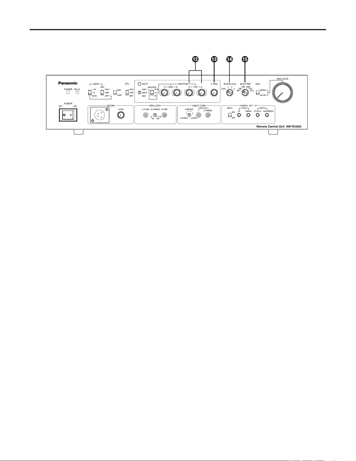
Red and blue pedestal adjustment controls
[PAINTING PED R/B]
These controls enable the black balance to be adjusted
finely.
When the black balance is automatically adjusted again
after it has been finely adjusted, it will return to the status
prior to the fine adjustment regardless of the positions of
these controls.
The function of the adjustment controls may be
implemented in steps since the processing involved uses
digital signals: This is normal and does not indicate any
malfunctioning.
Total pedestal adjustment control [T.PED]
This control enables the pedestal level of the video
signals to be adjusted. It is used when, for instance, the
pedestal level of two or more cameras is to be adjusted.
The function of the control may be implemented in steps
since the processing involved uses digital signals: This is
normal and does not indicate any malfunctioning.
Scene file switch [USER/1/2/3]
This switch is used to select the camera’s scene files.
USER: USER mode
1: Halogen light mode
2: Fluorescent light mode
3: Outdoor mode
Select the scene file which is optimally suited to the
shooting conditions.
(For details, refer to the camera’s operating instructions.)
Electronic shutter selector switch
[SHUTTER OFF/100/500/1000/ S/S /ELC]
This switch enables the shutter speed (OFF, 1/100, 1/500,
1/1000) as well as S/S and ELC to be selected.
S/S: This stands for synchro scan. The shutter speed
can be varied continuously at this setting.
(60.34 Hz to 15.75 kHz)
Display the camera’s menu using the menu
ON/OFF switch
, and set the shutter speed.
(For details, refer to the camera’s operating
instructions.)
ELC: At this setting, the electronic shutter is controlled,
and the light quantity is automatically adjusted.
Fine adjustment of ELC
ELC can be finely adjusted using the lens iris control
by setting the scene file switch
to [USER], setting
[Auto iris adjust] to [ON] using the camera’s menu and
setting the lens iris selector switch
to [AUTO] when this
switch is at [ELC].
(For details of the camera menus, refer to the camera’s
operating instructions.)
Note:
Smear may appear with high-brightness subjects when
the electronic shutter selector switch is set to ELC.
Parts and their functions
Page 9

9
Lens iris selector switch [IRIS MANU/AUTO]
The lens is set to automatic iris (ALC) if this switch is set
to [AUTO] when the iris selector switch on the lens is at
[AUTO]. The lens iris can now be finely adjusted using
the lens iris control
by setting the scene file switch
to [USER] and setting [Auto iris adjust] to [ON] using the
camera’s menu in this status.
(For details of the camera menus, refer to the camera’s
operating instructions.)
When the switch is set to [MANU], the lens iris can be
adjusted manually from closed to wide open using the
lens iris control
.
Lens iris control [IRIS LEVEL]
ALC (AGC and ELC) can be finely adjusted by setting
the lens iris selector switch
to [AUTO], the scene file
switch
to [USER], and [Auto iris adjust] to [ON] using
the camera’s menu.
When the lens iris selector switch
is set to [MANU], the
lens iris can be adjusted manually from closed to wide
open.
Note:
The ALC cannot be finely adjusted and the lens iris
cannot be adjusted when the iris selector switch on
the lens is set to a position other than [AUTO] (such as
[MANU]).
With some lenses, the open and close directions with
respect to the control directions may be reversed. If this is
the case, contact the lens manufacturer or your dealer.
Intercom connector [INCOM]
(XLR 4-pin connector)
A headset is connected here. Intercommunication is then
possible between the camera, RCU and live switcher.
Set the INCOM selector switch on the live switcher
(AW-SW350) to the [3-wire type].
1: GND
2: MIC (this is where the headset
microphone is connected)
3: GND
4: SPEAKER (this is where the headset
speaker is connected)
Use a dynamic type of microphone with an impedance
of approximately 200 ohms for the headset to be
connected.
Recommended headset:
HRM-201D (Ashida Sound Co., Ltd)
CC-26K (CLEAR-COM)
Intercom volume adjustment control
[INCOM LEVEL]
This is used to adjust the volume of the sound heard
through the speaker of the headset connected to the
INCOM connector.
Parts and their functions
Page 10

10
Horizontal phase adjustment control [H.PHASE]
This is used to adjust the horizontal phases of the
gen-lock input and video output when two or more
cameras are used at the same time.
Subcarrier phase coarse adjustment switch
[SC COARSE]
This is used to adjust the hue of the gen-lock input and
video output coarsely when two or more cameras are
used at the same time. When used in combination with
the subcarrier phase fine adjustment control
, the
adjustable range is greater than 360 degrees.
Subcarrier phase fine adjustment control
[SC FINE]
This is used to adjust the hue of the gen-lock input
and video output finely when two or more cameras are
used at the same time. When used in combination with
the subcarrier phase coarse adjustment switch
, the
adjustable range is greater than 360 degrees.
Cable compensation selector switch [COARSE]
This is set in line with the length of the cable between the
camera and RCU.
Switch position Cable length
1 Less than 246 ft. (75 m)
2 246 to 492 ft. (75 to 150 m)
3 492 to 754.4 ft. (150 to 230 m)
4 754.4 to 984 ft. (230 to 300 m)
(The cable lengths above are approximations only.)
Y gain adjustment control [ADJUST Y]
This is used to adjust the Y (luminance) level of the video
output signals to match the cable length.
(Select the cable length using the cable compensation
selector switch
before adjusting the level. The chroma
amount is also varied by this control.)
Chroma gain adjustment control
[ADJUST CHROMA]
This is used to adjust the chrominance level of the video
output signals to match the cable length.
(Select the cable length using the cable compensation
selector switch
and adjust the Y level of the video
output signals using the Y gain adjustment control
before adjusting the level.)
Menu ON/OFF switch [MENU OFF/ON]
OFF: Only the camera’s images are output to the video
output.
ON: The camera’s images and superimposed camera’s
menu are output to the video output.
Menu items can be selected and data changed using
the item UP switch
, item DOWN switch , DATA
YES/UP switch
and DATA NO/DOWN switch .
For details on the menu items and contents, refer to
the camera’s operating instructions.
Item UP switch [ITEM UP]
When this is pressed while a menu is displayed, the item
which is the next one up from the current item on the
menu can be selected.
Item DOWN switch [ITEM DOWN]
When this is pressed while a menu is displayed, the item
which is the next one down from the current item on the
menu can be selected.
DATA YES/UP switch [DATA YES/UP]
When this is pressed while the main menu is displayed,
the submenus of the items are displayed.
When it is pressed while a submenu is displayed, the
setting is incremented.
DATA NO/DOWN switch [DATA NO/DOWN]
When this is pressed while the main menu is displayed,
the item which is the next one down from the current item
on the menu can be selected.
When it is pressed while a submenu is displayed, the
setting is decremented.
Parts and their functions
Page 11

11
Camera cable connector [CAMERA]
(26-pin connector)
The camera’s cable (such as the AW-CA50A26) is
connected here.
Contact-type pan/tilt head control connector
[PAN/TILT CONTROL IN]
(D-SUB 15-pin connector)
This has the same shape as the tally/intercom input/
output connector. Take care not to confuse the two
when connecting them.
A controller for controlling the lens (a lens with zoom
and focus servo) and pan/tilt head (up, down, left,
right, defroster, wiper, etc.) is connected here. (Only a
contact-type controller can be connected.)
Pin No. Signal Name
1 LEFT
2 RIGHT
3 UP
4 DOWN
5 FAR
6 NEAR
7 TELE
8 WIDE
9 DEFROSTER
10 WIPER
11 COMM
12 +5 V
13 +V (+7.5 V)
14 –V (+2.5 V)
15 GND
The optional board must be installed in the camera in
order to use a contact-type pan/tilt head. For details,
refer to the camera’s operating instructions.
When the control pins (#1 to #10) are connected to the
COMM pin (#11), the control signals are sent from the
RCU to the camera.
When the controller is to be fabricated, connect a
resistor with a resistance of 1 to 10 kilohms (1/8 W or
more) between the COMM pin and +5 V pin.
Ensure that both the LEFT and RIGHT pins are not
connected to the COMM pin at the same time.
Similarly, do not connect both the UP and DOWN, FAR
and NEAR or WIDE and TELE pins to the COMM pin
at the same time.
Pins #12 to #15 are used when exercising lens control
only. To do this, connect the controller’s FOCUS CONT
pin to NEAR (pin #6) and its ZOOM CONT pin to WIDE
(pin #8). (Normally, pins #12 to #15 are not used when
exercising control by contacts.)
Gen-lock input/output connector
[G/L IN/OUT]
(75-ohm automatic termination)
The external sync signals (black burst signals or
composite signals) from another system are connected
here.
Note:
The input signals must be connected to the BNC
connector marked “IN” (75-ohm automatic termination).
If it is connected to the BNC connector marked “OUT,” a
high-impedance state will result, and the connector will
not be terminated by the 75-ohm resistance.
AUX signal input/output connector
[AUX IN/OUT] (75-ohm automatic termination)
Connect the line view signals from a live switcher or other
device here.
Note:
The input signals must be connected to the BNC
connector marked “IN” (75-ohm automatic termination).
If it is connected to the BNC connector marked “OUT,” a
high-impedance state will result, and the connector will
not be terminated by the 75-ohm resistance.
Parts and their functions
Rear panel
Page 12

12
Video output connectors [VIDEO1, VIDEO2]
The video signals from the camera after cable
compensation are output from these connectors. (The
same signal is output from connectors 1 and 2.)
Connect the connectors to the video input connectors
on the live switcher, color monitor, VTR or other device.
(Output impedance: 75 ohms)
SYNC output connector [SYNC]
The composite sync signal is output from this connector.
Connect the connector to the gen-lock input connector on
the color monitor or other device.
(Output impedance: 75 ohms)
RGB/Y, PR and PB/YC output connectors
[R/PR/C, G/Y/Y, B/PB]
If a camera such as the AW-E650 with RGB/Y, PR and
PB/YC signal output facilities is connected to the remote
control unit, its signals are output from these connectors.
(Output impedance: 75 ohms)
The RGB/Y, PR or PB/YC signals are selected using
the camera’s menu. (For details, refer to the camera’s
operating instructions.)
S-Video output connector [S-VIDEO OUT]
(4-pin S-connector)
The same signals as the ones output from the R/PR/C
and G/Y/Y connectors among the RGB/Y, PR and PB/YC
output connectors are output from this connector.
(Output impedance: 75 ohms)
The YC signals are selected using the camera’s menu,
and connected to a color monitor or other device
equipped with an S-Video input connector.
Note:
When the RGB/Y, PR and PB/YC output connectors
and S-Video output connector are used at the same
time, the level of the output signals will be reduced.
Therefore, use either connectors
or connector in
line with the connectors used on the device connected to
the remote control unit.
Tally/intercom input/output connector
[TALLY/INCOM] (D-SUB 15-pin connector)
Connect this to the TALLY & INCOM connector on the live
switcher (AW-SW350).
Set the INCOM selector switch on the live switcher
(AW-SW350) to [3-wire type].
When inputting the tally control signals from another
device, input them with 0V for ON and open for OFF.
Pin No. Signal Name
1 TALLY
6 INCOM MIC
7 INCOM GND
8 INCOM SP
11 TALLY GND
Fuse holder [FUSE]
Fuse used: HT1.6AN5 (AC 250 V, 1.6 A)
AC power socket [AC IN]
Attach one end of the power cord provided to this socket
and the other end to the AC 120V (60 Hz) power supply.
Parts and their functions
Page 13

13
Connections
Before proceeding with the connections, ensure that the power to all the devices is off.
Be absolutely sure to use the AW-CA50A26 RCU cable to connect the RCU to the camera.
When extending the cable, use the extension-use studio cable (WV-CA26U15, WV-CA26U30 or WV-CA26U100) and
extension-use joint connector (WV-CA26T26).
The maximum length to which the cable can be extended is 984 ft. (300 m) (for a camera body and lens).
When using the studio card (AW-PB305) and attaching a viewfinder, it can be extended up to 328 ft. (100 m).
When the power switch of the RCU is set to ON, the power indicator LED lights up, and the camera is controlled from the
RCU.
Notes:
When the R/G/B, Y/PR/PB and Y/C signals are used, select the required signals using the camera’s menu.
When using the S-Video signals, select Y/C using the camera’s menu. Furthermore, use either the S-Video connector or
BNC connectors, and leave the other connectors unconnected.
The S-Video connector and BNC connectors cannot be used at the same time.
Connect either the VIDEO OUT BNC connector or S-Video connector to the AW-SW350 live switcher.
Use an intercom headset suited to all the devices.
Fabricate the TALLY & INCOM cables without mixing up the signals.
Remote control unit
AW-RC600
AC adapter
AW-PS505A
Live switcher
AW-SW350
Convertible camera + lens +
electronic viewfinder
The AW-PB305 studio card and viewfinder installation bracket are
required to connect an electronic viewfinder to a convertible camera.
Headset
AC 120 V
Supplied AC cable
TALLY&INCOM
VIDEO IN (S-VIDEO)
To VIDEO IN
To PGM OUT or PVW OUT
To BB OUT
TALLY&INCOM cable
S-VIDEO cable
BNC coaxiale cable
To RGB monitor, etc.
RCU cable
AW-CA50A26
50-pin connector
of camera
AC120 V
BNC coaxiale cable
BNC coaxiale cable
Headset
Headset
Page 14

14
1. Turn on the power.
Set the unit’s power switch to [ON].
Power switch
2. Proceed with the cable compensation and gen-lock adjustments.
Gen-lock adjustment Cable compensation
3. Adjust the white balance.
This adjustment must be performed when the unit is used for the first time or when the unit has not been used for a
prolonged period.
It must also be performed when the light conditions or brightness has changed.
Once the white balance has been adjusted, there is no need to adjust it again provided that the unit will be used under the
same conditions.
When the white balance selector switch is used at the ATW setting, the white balance need not be adjusted.
4. Adjust the black balance.
This adjustment must be performed when the unit is used for the first time or when the unit has not been used for a
prolonged period.
It must also be performed when the ambient temperature has changed significantly or at the beginning of a new season.
Once the black balance has been adjusted, there is no need to adjust it again provided that the unit is going to be used
under the same conditions.
Black balance adjustment
White balance adjustment
5. Set the switches to match the shooting conditions.
Operating procedure
Page 15

15
Cable compensation
1. Turn the cable compensation selector switch to match the length of the cable connecting the camera and the RCU.
Switch position Cable length
1 Less than 246 ft. (75 m)
2 246 to 492 ft. (75 to 150 m)
3 492 to 754.4 ft. (150 to 230 m)
4 754.4 to 984 ft. (230 to 300 m)
(The cable lengths above are approximations only.)
2. Connect the wave form monitor (or oscilloscope) and vectorscope to the video output connectors.
(75 ohms termination)
3. Switch the camera signal to color bar and adjust the Y (luminance) level and chrominance level with the Y gain
adjustment control and the chroma gain adjustment control, respectively.
If the camera output color bar is normal, adjust the values as below.
Chrominance level: Each color should be in the vectorscope frame.Y Level: 100 IRE (0.714 Vp-p)
100 IRE
Y
L
G
Y
M
G
G
R
B
–I
O
20%
dG
dO
10
%
dG
10°
10°
0°
Adjustment
Page 16

16
Adjustment
White balance adjustments
Automatic adjustment (AWC)
Two sets of color temperature conditions can be stored in the memory.
When using the unit under the same conditions as the ones stored in the memory, there is no need to re-adjust the white
balance.
When the white balance is automatically adjusted again, the data in the memory is rewritten.
Auto setting indicator LED
White balance selector switch
Red and blue gain adjustment controls
The white object must occupy over
10 % of the monitor screen area.
Auto white/auto black setting switch
1. Set the white balance selector switch to [A] or [B].
2. Fill the screen with a white object.
The white object must have a size which is at least 10% of the screen size, and it must be displayed in the screen center.
Do not allow shiny objects and very bright objects to appear on the screen.
3. The white balance can be automatically adjusted by setting the auto white/auto black setting switch to [AWC].
While the white balance is being automatically adjusted, the auto setting indicator LED starts blinking: it goes off if the
adjustment is successful and lights up if it is not successful.
If the adjustment is not successful, change the lens iris setting, lighting, subject and/or other conditions, and try performing
the automatic adjustment again.
4. After automatically adjusting the white balance, use the red and blue gain adjustment controls to finely adjust the
white balance.
Note:
When the white balance is automatically adjusted again after it has been finely adjusted, it will return to the status prior to the
fine adjustment regardless of the positions of the red and blue gain adjustment controls.
Automatic color temperature search (ATW)
When the white balance selector switch is set to [ATW], the camera provides compensation automatically in such a way
that the white balance is adjusted automatically even when the light source or color temperature has changed. The result is
images in which nothing feels odd or out of place.
Notes:
The white balance may shift if there are no white objects on the screen.
With some light sources or at some color temperatures, it may not be possible to compensate the white balance
completely.
Page 17

17
Adjustment
Auto setting indicator LED
Red and blue pedestal adjustment controls
Auto white/auto black setting switch
Black balance adjustments
Automatic adjustment (ABC)
1. The black balance can be automatically adjusted by setting the auto white/auto black setting switch to [ABC].
While the black balance is being automatically adjusted, the auto setting indicator LED starts blinking: it goes off if the
adjustment is successful and lights up if it is not successful. If the adjustment is not successful, try performing the automatic
adjustment again.
(If the black balance is automatically adjusted with the lens iris selector switch at [AUTO], the lens iris will be closed
automatically. Check that the lens iris is completely closed.)
2. After automatically adjusting the black balance, use the red and blue pedestal adjustment controls to finely adjust
the black balance.
Note:
When the black balance is automatically adjusted again after it has been finely adjusted, it will return to the status prior to the
fine adjustment regardless of the positions of the red and blue pedestal adjustment controls.
Page 18

18
Adjustment
Gen-lock adjustment
When using the gen-lock function, the phases of the signals must be adjusted to bring the phases into alignment with the other
devices and camera.
Before proceeding with the adjustment, switch the camera’s video signals to color bar signals.
Horizontal phase adjustment
Using a dual-trace oscilloscope, monitor the waveforms of the gen-lock input signals (black burst signals) and video output
signals, and align the horizontal phase using the horizontal phase adjustment control.
Hue adjustment
1. Connect the video output signals to a vectorscope.
2. Set the vectorscope to the gen-lock mode using the same gen-lock signals.
3. Observe the waveforms on the vectorscope, and use the subcarrier phase coarse adjustment switch and the
subcarrier phase fine adjustment control to set the colors of the color bars to the prescribed phase.
External synchronizing
input signal
(black burst signal)
Video output signal
Adjust the horizontal phase
Horizontal phase adjustment control
Subcarrier phase coarse adjustment
switch
Subcarrier phase fine adjustment
control
Y
L
G
Y
M
G
G
R
B
–I
O
20%
dG
dO
10
%
dG
10°
10°
0°
Page 19

19
Menu item setting
The settings of the convertible camera were preset when the camera was shipped from the manufacturing plant. However, the
menu items can be set or changed for each mode to match the actual shooting conditions. For details, refer to the camera’s
operating instructions.
Menu displays
These displays can be set when the menu ON/OFF switch is set to [ON].
Setting procedure
Press the item UP switch to select the item which is the next one up from the current item on the menu.
Press the item DOWN switch to select the item which is the next one down from the current item on the menu.
When the DATA YES/UP switch is pressed while the main menu is displayed, the submenus of the items are displayed.
When it is pressed while a submenu is displayed, the setting is incremented.
When the DATA NO/DOWN switch is pressed while the main menu is displayed, the item which is the next one down from
the current item on the menu. When it is pressed while a submenu is displayed, the setting is decremented.
After setting or changing the menu items, set the menu ON/OFF switch to [OFF].
From this point on, the camera will operate under these settings.
Menu ON/OFF switch
Item UP switch
Item DOWN switch
DATA YES/UP switch
DATA NO/DOWN switch
Page 20

20
When the unit is to be mounted on a EIA 19-inch rack, use rack mount angles (provided) and four mounting screws (M410)
(provided).
1. Turn off the power switch of the unit.
2. Remove four screws fixing the rubber feet and remove the four rubber feet from the bottom of the unit.
3. Fix the rack angle handle by using four rack angle handle fixing screws.
4. Attach the rack mount angles on both sides and fix them by using four mounting screws provided with the rack
mount angle.
5. Install the unit on the EIA 19-inch rack by using four screws (locally purchased).
Rack mounting
Remove rubber feet.
Fix four screws (not provided).
Do not use the unit on the place affected by the vibration.
When the fan is used to keep the temperature in the rack within 122°F (+50°C), it should be put apart from the monitor.
Cautions:
Rack angle handle
Rack mount angle fixing screws
(provided)
Rack mount angle
Rack mount angle
fixing screws
(provided)
Mounting screws
(provided)
Mounting screws
(provided)
Page 21

21
Appearance
Unit: inch (mm)
16-9/16 (420)
9-13/16 (250) 3-7/16 (88)
Page 22

22
Power supply: 120V AC, 60 Hz
Power consumption: Approx. 67 W
Video output: Composite signal 1.0 Vp-p/752 (BNC connector)
R/G/B, Y/PR/PB, Y/C signal (switch)
1 each (BNC connector)
R,B: 0.7 Vp-p/75
, G: 1.0 Vp-p/75 (with SYNC)
Y: 1.0 Vp-p/75
, PR, PB: 0.7 Vp-p/75
Y: 1.0 Vp-p/75
, C: 0.286 Vp-p/75
SYNC signal (Negative polarity) 2 Vp-p/75
1 (BNC connector)
S-Video signal Y: 1.0 Vp-p/75
, C: 0.286 Vp-p/75 (S-Video connector)
The above values are the values which are cable-compensated by this unit after they has
been output from the camera at a regular level.
Genlock input: 1.0 Vp-p composite video signal or black burst signal/75
or High impedance (automatic
terminated BNC connector)
AUX input: 1.0 Vp-p composite video signal/75
or High impedance (automatic terminated BNC connector)
Pan/tilt head control input: Pan/tilt head (up, down, right, left, defroster, wiper), lens (zoom, focus)
D-SUB 15-pin (female)
Switch function: Gain up selection, AGC selection, color bar/camera selection, detail compensation selection,
auto white/auto black set, white balance selection, scene file, electronic shutter switch,
lens iris selection, subcarrier phase coarse adjustment, cable compensator selection, user set,
menu, item up, item down
Adjustment function: R•B gain, R•B pedestal, total pedestal, lens iris adjustment, INCOM level, horizontal phase,
subcarrier phase finely adjustment, Y gain adjustment, chroma gain adjustment
TALLY/INCOM connector: D-SUB 15-pin (female)
INCOM connector: XLR 4-pin (male)
Maximum cable length: 984 ft. (300 m) (convertible camera unit)
328 ft. (100 m) (AW-E860 + AW-PB305 + Viewfinder)
Operating temperature: 14°F to 113°F (–10°C to +45°C)
Dimensions (WHD): 16-9/163-7/169-13/16 (42088250 mm)
(excluding protrusions)
Weight: Approx. 12.3 lbs. (5.6 kg)
Finish: AV ivory paint (color resembling Munsell 7.9Y 6.8/0.8)
Weight and dimensions shown are approximate.
Specifications are subject to change without notice.
Specifications
indicates safety information.
Page 23

Page 24

PANASONIC BROADCAST & TELEVISION SYSTEMS COMPANY
UNIT COMPANY OF PANASONIC CORPORATION OF NORTH AMERICA
Executive Office:
One Panasonic Way 4E-7, Secaucus, NJ 07094 (201) 348-7000
EASTERN ZONE:
One Panasonic Way 4E-7, Secaucus, NJ 07094 (201) 348-7621
Southeast Region:
1225 Northbrook Parkway, Ste 1-160, Suwanee, GA 30024 (770) 338-6835
Central Region:
1707 N Randall Road E1-C-1, Elgin, IL 60123 (847) 468-5200
WESTERN ZONE:
3330 Cahuenga Blvd W., Los Angeles, CA 90068 (323) 436-3500
Government Marketing Department:
52 West Gude Drive, Rockville, MD 20850 (301) 738-3840
Broadcast PARTS INFORMATION & ORDERING:
9:00 a.m. – 5:00 p.m. (PST) (800) 334-4881/24 Hr. Fax (800) 334-4880
Emergency after hour parts orders (800) 334-4881
TECHNICAL SUPPORT:
Emergency 24 Hour Service (800) 222-0741
Panasonic Canada Inc.
5770 Ambler Drive, Mississauga, Ontario L4W 2T3 (905) 624-5010
Panasonic de Mexico S.A. de C.V.
Av angel Urraza Num. 1209 Col. de Valle 03100 Mexico, D.F. (52) 1 951 2127
Panasonic Puerto Rico Inc.
San Gabriel Industrial Park, 65th Infantry Ave., Km. 9.5, Carolina, Puerto Rico 00630 (787) 750-4300
© 2006 Matsushita Electric Industrial Co., Ltd. All rights reserved.
Printed in Japan
VQTB0116 F0306S0
D
P
 Loading...