

Panasonic AW-PH650N, AWPH650 - PAN/TILT HEAD Operating Instructions Manual
Before attempting to connect, operate or adjust this product,
please read these instructions completely.
Outdoor Pan/Tilt Head
AW-PH650N
Printed in Japan
F0406Y1056 D VQTB0104-1
2
indicates safety information.
This class A digital apparatus complies with
Canadian ICES-003.
Cet appareil numérique de la classe A est
conforme à la norme NMB-003 du Canada.
For CANADA
Safety precautions
CAUTION
RISK OF ELECTRIC SHOCK
DO NOT OPEN
CAUTION: TO REDUCE THE RISK OF ELECTRIC SHOCK,
DO NOT REMOVE COVER (OR BACK).
NO USER SERVICEABLE PARTS INSIDE.
REFER TO SERVICING TO QUALIFIED SERVICE PERSONNEL.
The lightning flash with arrowhead symbol,
within an equilateral triangle, is intended to
alert the user to the presence of uninsulated
“dangerous voltage” within the product’s
enclosure that may be of sufficient magnitude
to constitute a risk of electric shock to
persons.
The exclamation point within an equilateral
triangle is intended to alert the user to the
presence of im po rtant operating and
maintenance (service) instructions in the
literature accompanying the appliance.
WARNING:
• TO REDUCE THE RISK OF FIRE OR ELECTRIC
SHOCK, DO NOT EXPOSE THIS APPARATUS TO
RAIN OR MOISTURE.
• THE APPARATUS SHALL NOT BE EXPOSED TO
DRIPPING OR SPLASHING AND THAT NO
OBJECTS FILLED WITH LIQUIDS, SUCH AS
VASE S, SHA LL BE PLACED ON TH E
APPARATUS.
CAUTION:
TO REDUCE THE RISK OF FIRE OR SHOCK
HAZARD AND ANNOYING INTERFERENCE, USE
THE RECOMMENDED ACCESSORIES ONLY.
FCC Note:
This equipment has been tested and found to comply
with the limits for a class A digital device, pursuant to
Part 15 of the FCC Rules. These limits are designed
to provide reasonable protection against harmful
interference when the equipment is operated in a
commercial environment. This equipment generates,
uses, and can radiate radio frequency energy, and if
not installed and used in accordance with the
instruction manual, may cause harmful interference to
radio communications. Operation of this equipment in
a residential area is likely to cause harmful interference
in which case the user will be required to correct the
interference at his own expense.
Warning:
To assure continued FCC emission limit compliance,
the user must use only shielded interface cables when
connecting to external units. Also, any unauthorized
changes or modifications to this equipment could void
the user’s authority to operate it.
CAUTION:
In order to maintain adequate ventilation, do not
install or place this unit in a bookcase, built-in
cabinet or any other confined space. To prevent
risk of electric shock or fire hazard due to
overheating, ensure that curtains and any other
materials do not obstruct the ventilation.
Note:
The rating plate (serial number plate) is on the
bottom of the unit.
The socket outlet shall be installed near the
equipment and easily accessible or the mains plug or
an appliance coupler shall remain readily operable.
A warning that an apparatus with CLASS I construction
shall be connected to a MAINS socket outlet with a
protective earthing connection.
WARNING:
TO PR EVENT INJURY, THIS APPARATUS
MUST BE SECURELY ATTACH ED TO THE
FLOOR / WAL L IN ACCORD ANCE WI T H
THE INSTALLATION INSTRUCTIONS.
This product contains a CR Coin Cell Lithium Battery
which contains Perchlorate Material
— special
handling may apply.
See www.dtsc.ca/gov/hazardouswaste.perchlorate.
3
indicates safety information.
1) Read these instructions.
2) Keep these instructions.
3) Heed all warnings.
4) Follow all instructions.
5) Do not use this apparatus near water.
6) Clean only with dry cloth.
7) Do not block any ventilation openings. Install in
accordance with the manufacturer’s instructions.
8) Do not insta ll near a ny heat sou rces
such as radiators, heat registers, stoves, or other
apparatus (including amplifiers) that produce heat.
9) Do not defeat the safety purpose of the polarized
or grounding-type plug. A polarized plug has two
blades with one wider than the other. A groundingtype plug has two blades and a third grounding
prong. The wide blade or the third prong are
provided for your safety. If the provided plug does
not fit into your outlet, consult an electrician for
replacement of the obsolete outlet.
10) Protect the power cord form being walked on or
pinched par ticular ly at p lugs, convenience
receptacles, and the point where they exit from
the apparatus.
11) Only use attachments/accessories specified by the
manufacturer.
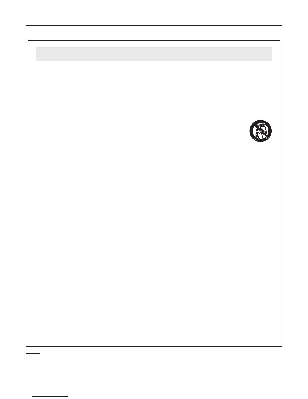
12) Use only with the cart, stand, tripod,
bracket, or table specified by the
manufactur er, or sold with the
apparatus. When a cart is used, use
caution when movin g the cart/
apparatus combination to avoid
injury from tip-over.
13) Unplug this apparatus during lightning storms or
when unused for long periods of time.
14) Refer all servicing to qualified service personnel.
Servicing is required when the apparatus has
been damaged in any way, such as power-supply
cord or plug is damaged, liquid has been spilled or
objects have fallen into the apparatus, the
apparatus has been exposed to rain or moisture,
does not operate normally, or has been dropped.
Read these operating instructions carefully before using the unit. Follow the safety instructions on the unit and the
applicable safety instructions listed below. Keep these operating instructions handy for future reference.
IMPORTANT SAFETY INSTRUCTIONS
Safety precautions

4
Introduction ....................................................................... 4
Accessories ...................................................................... 4
Precautions for use
.......................................................... 4
Installation precautions ................................................... 5
Mounting (Pan/tilt head) ................................................... 6
Precautions for installation .............................................. 6
How to install ................................................................... 6
Mounting (AC adapter) ..................................................... 7
Precautions for installation .............................................. 7
How to install ................................................................... 7
Parts and their functions .................................................
9
Main unit (Pan/tilt head) .................................................. 9
Housing unit ..................................................................
10
AC adapter unit ............................................................. 11
Supplied cable unit ........................................................ 12
Installation ....................................................................... 14
Installing the housing mount frame ............................... 14
Cable compensation circuit settings ..............................
15
CPU circuit board switch settings ..................................
16
How to install the camera ..............................................
17
How to install the housing ............................................. 24
Connections .................................................................... 25
Concerning the connectors inside the housing ............. 25
Connecting the cameras and housing ........................... 26
Precautions when controlling the AK-HC1500 from the AW-CB400
... 29
Connections with AC adapter ........................................ 29
Example of connections when using a convertible camera
... 30
Example of connections when using a multi purpose camera
... 31
Limiters ............................................................................
32
Setting the limiters .........................................................
32
Releasing the limiters .................................................... 33
Setting the limiter again ................................................. 33
Replacement of consumable parts ...............................
34
Appearance ..................................................................... 36
Main unit ........................................................................
36
Housing unit ..................................................................
37
AC adapter unit .............................................................
38
Cable specifications ....................................................... 39
Specifications ................................................................. 42
Contents
This fitted type of outdoor pan/tilt head can be rotated
upward by 50 degrees, downward to 95 degrees and
horizontally by 320 degrees.
Equipment such as a camera and lens with a total weight
of 22 lbs (10 kg) can be mounted on the unit. (excluding
housing)
The shooting positions and settings for up to 50 positions
can be registered as preset memory data.
The unit’s housing comes with a wiper and defroster.
The unit’s internal temperature is controlled by a heater
and ventilating fan.
The unit meets the IPX4 water-proofing protection
standard.
Introduction
Main unit (AW-PH650 U02) .............................................. 1
Outdoor camera housing (AW-PH650 U03) ................... 1
AC adapter (AW-PH650 U01) ........................................... 1
Power cable 98.4 ft (30 m) (VEEB0152) .......................... 1
Multi cable 32.8 ft (10 m) (VEEB0133) ............................ 1
Camera cable 1.3 ft (40 cm) each ................................... 1
Convertible camera cable (VEEB0176) ...................... 1
AK-HC900 series cable (VEEB0177) ........................... 1
AK-HC1500 cable (VEEB0178) .................................... 1
Accessories
Lens holder, string and set of screws ........................... 1
Camera mounting spacer and set of screws ................ 1
Pole mounting plate and set of screws ......................... 1
Set of Allen keys
.............................................................. 1
Housing mount frame ..................................................... 1
Filter .................................................................................. 1
Set of cable ties
............................................................... 1
•
For details on the cables, refer to page 12 and following.
The AW-PH650 uses a manganese dioxide-lithium battery
(CR2032).
Before discarding the pan/tilt head or its printed circuit
boards, be absolutely sure to remove the battery.
Be absolutely sure to dispose of the removed battery
in accordance with the applicable domestic laws and
regulations.
Do not throw out the battery along with the general
household garbage.
For the procedure to remove the battery, refer to the section
on replacing the battery in “Replacement of consumable
parts” (page
34).
Precautions for use
Lithium battery

5
Installation precautions
Do not install this unit by suspending it, and do not install
it on its side.
While factoring in the weights of the unit and the load that
the unit will bear, select an installation location which is
conducive to fastening the unit securely and which is level
and without unevenness. Fasten the unit securely so that
it will not shake or be rickety when it is at rest or being
rotated. Failure to secure the unit properly or looseness
of the bolts may cause the product to fall off or fall down,
possibly resulting in an accident.
Bolts for installing the unit are not provided with the unit.
Select bolts which are sufficiently strong and made of a
material capable of with standing outdoor use.
The maximum load which the unit can bear is 22 lbs (10
kg) (excluding the housing).
The unit cannot be used with a load in excess of 22 lbs
(10 kg).
Upon completion of the pan/tilt head’s installation, mount
the housing. To prevent looseness in the places where
the unit is mounted, be absolutely sure to use parts such
as flat washers and spring washers for its installation.
The power must be off while the installation or connection
work is underway.
Do not set the power switch of the AC adapter to ON until
after checking that no mistakes have been made upon
completion of all the installation and connection work.
A ventilating fan is provided inside the housing. The fan
can be controlled using the H/F button on the controller
but it should normally be left at ON. Furthermore, d
o
not block it or obstruct the ventilation while the unit is
operating. Otherwise, heat will build up inside, possibly
causing a fire. The ventilating fan is a consumable: as
a general rule, replace it after abo
ut 40,000 hours of
operation.
(Be absolutely sure to ask your dealer to replace the fan.)
Steps to be taken prior to installation
The AW-PH650 has function selector switches on its
main unit (pan/tilt head) and housing.
Since it may prove difficult to change the positions
of these switches after installation, refer to
cable
compensation circuit settings (page 15), CPU circuit
board switch settings (page 16) and
settings of
the camera control selector switch inside the housing
(page 25) prior to installation.
Then set the switches to the positions that correspond to
the operating conditions.
Be absolutely sure to use water-proof connecting cables.
Do not install the unit where the temperature will drop
below
–4°F (–20°C) or rise above 113°F (45°C) since
operation will become unstable under these temperature
conditions.
Be absolutely sure to use the AC adapter provided
with the unit as the power source of the pan/tilt head.
(Batteries or other power supplies cannot be used.)
The cable for connecting the power supply to the
AC adapter is locally
purchased. Read the operating
instructions, and heed all the safety precautions to
connect the cable.
Do not turn the rotating part of the pan/tilt head by hand.
If it is dropped or subjected to strong impact, it may fail or
malfunction.
Install the unit and set a travel range (limiters) to ensure
that it will not come into contact with any objects in the
vicinity when the unit including the housing has swiveled.
Do not operate the controls on the pan/tilt head under
any circumstances while installation or other work is
underway.
Before checking the pan/tilt head’s operation and before
actually using it, check that nobody is within the range of
its rotation.
Do not install the unit in a kitchen or other location where
there is a lot of oil or grease.
Check the following accessories supplied.
Product QTY Specification
1 Power cable 1 Approx. 98.4 ft. (30 m)
2 Multi cable 1 Approx. 32.8 ft. (10 m)
3 Camera cable 1 For convertible camera
4 Camera cable 1 For AK-HC900 series
5 Camera cable 1 For AK-HC1500
6 Lens holder 1 For a large lens
7 Screws for lens holder 2 For M5 and M6
8 Washers for lens holder 2 ø6
9 String 1 Approx. 2.8 ft. (85 cm)
10 Camera mounting spacer 1
11
Screws for camera mounting spacer
4 1/4", length: 13 mm
12
Washers for camera mounting spacer
4 ø6
13 Positioning screw 1 M5, length: 8 mm
14 Pole mounting plate (AC adapter) 1
15 Screws for pole mounting plate 4 M8, length: 14 mm
16 Washers for pole mounting plate 8 ø8
17 Allen keys 3 For M5, M6 and M8
18 Housing mount frame 1
19 Screws for housing mount frame 4 M5, length: 30 mm
20 Washers for housing mount frame 8 ø5
21 Filter 1
22 Cable ties 5 Approx. 100 mm
6
Mounting (Pan/tilt head)
Precautions for installation
Do not install this unit by suspending it, and do not install
it on its side.
Using the four pan/tilt head mounting holes, fasten the
unit securely with bolts which are long enough.
The mounting holes have a diameter of 3/8
” (10 mm). Use
sufficiently long bolts with an 5/16” (8 mm) diameter. Do
not use bolts with a diameter smaller than 5/16” (8 mm).
Use hexagon head bolts or hexagon socket head bolts,
for instance, which can be tightened up securely using a
tool and which are made of a material and with a finish
that will withstand outdoor use.
Be absolutely sure to use parts such as flat washers or
spring washers together with the bolts to prevent the bolts
from coming loose.
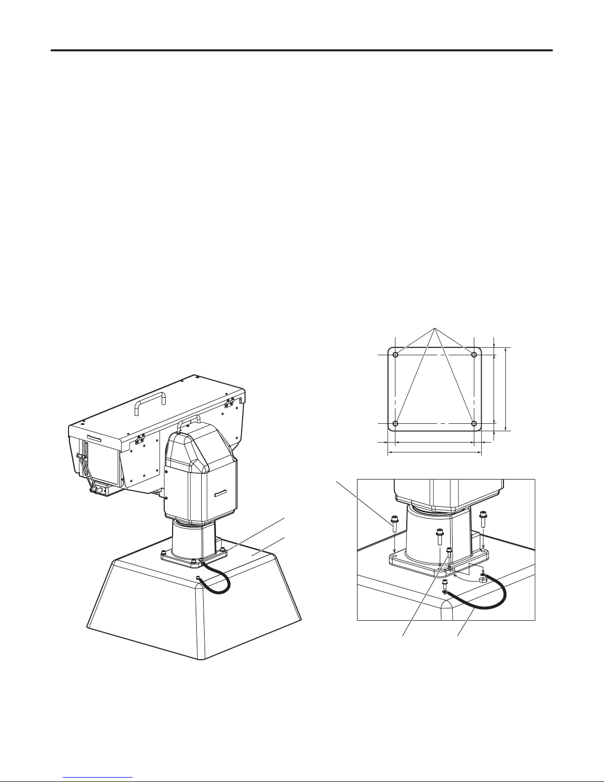
How to install
Attach one end of the anti-fall wire to the mounting hole,
and secure the other end to the mounting base or other
sturdy place.
The diameter of the hole where the anti-fall wire is
attached is 6.5 mm. Attach the wire using the anti-fall wire
mounting bolts with a 6 mm diameter and a length of 16
mm, flat washers, spring washers and nuts.
Ensure that the anti-fall wire is strong enough to bear the
weight of the entire pan/tilt head (head, housing, camera
and cable).
The diameter of the four pan/tilt
head mounting holes are 3/8 (10).
<Dimensions of area where unit is mounted>
6-5/16 (160)
7-1/2 (190)
5-1/2 (140)
6-11/16 (170)
Mounting area
Mounting base
Mounting bolts
Anti-fall wire bolt Anti-fall wire
Unit: inch (mm)
9/16
(15)
9/16
(15)
9/16
(15)
9/16
(15)
7
Mounting (AC adapter)
Precautions for installation
Be sure to use water-proof connecting cables.
Be sure to keep AC power switched off during installation and connection.
Before pressing the power switch on, make sure that all parts, including the housing and pan/tilt head, have been installed
and connected completely and free of errors.
Do not install the AC adapter at a cold place [below –4°F (–20°C)] or a hot place [over 113°F (45°C)] because extremely low
or high temperature will cause operation instability.
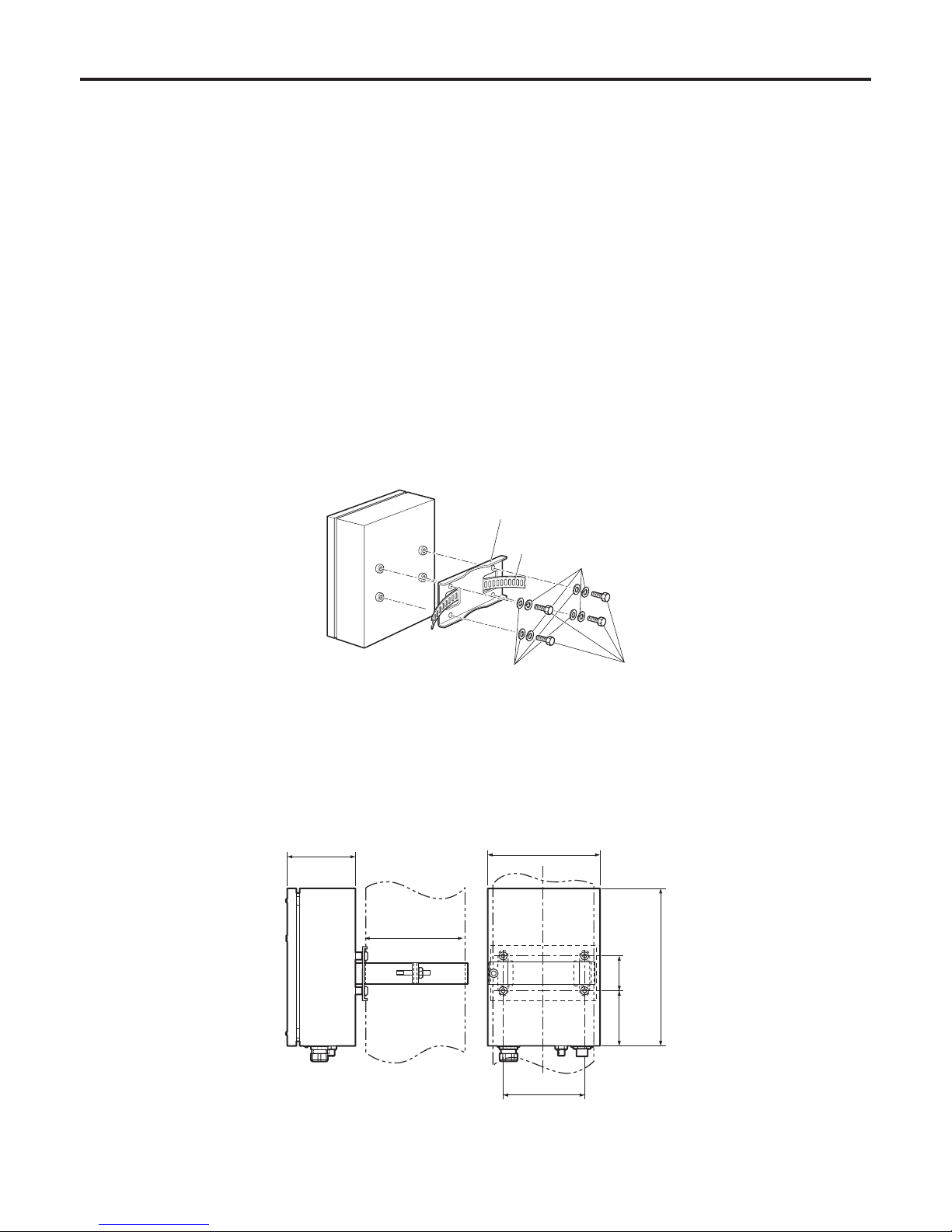
How to install
Fasten the pole mounting plate (supplied) and the belt (to be locally purchased) on the back of the AC adapter with the four bolts,
flat washers and spring washers (For M8: supplied).
Fasten the AC adapter to the pole using the pole mounting plate and the belt.
4-3/4”
(121 mm)
7-7/8”
(200 mm)
Pole
ø7-7/8” (200 mm)
11”
(280 mm)
5-3/4”
(146 mm)
3-7/8”
(98 mm)
2-7/16”
(62 mm)
Pole mounting plate
Belt [width: 1-3/4” (45 mm) or less]
Bolts (4 pcs.)
Spring washers
Flat washers
8
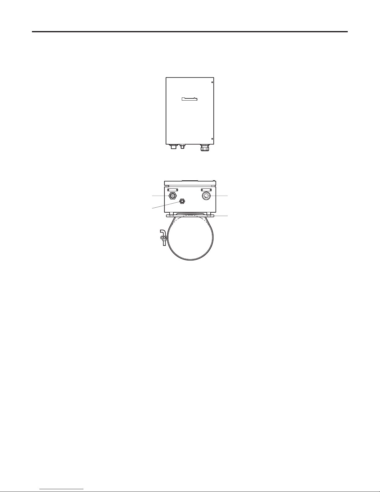
Mounting (AC adapter)
Connect the cables. (Refer to the “Connections”.)
Make the distance between the AC adapter and pan/tilt head less than the length (30 m) of the power cable supplied.
AC power input
Pole mounting plate
Ventilation opening
Pan/tilt head
9
Parts and their functions
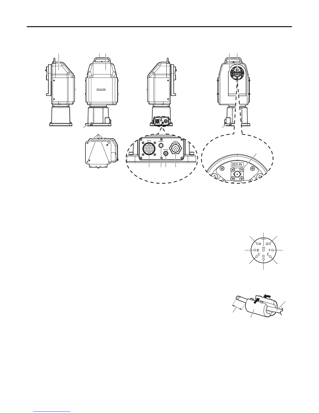
Main unit (Pan/tilt head)
Main unit cover
The sunshade cover and main unit cover must be
removed when the cable compensation circuit or landing
characteristics are to be changed.
Grip
Used in carrying, installing, or lifting the pan/tilt head.
Sunshade cover
This cover protects the pan/tilt head from direct exposure
to sunlight.
Rotary arm
Mount the housing after having installed the housing
mount frame.
I/F connector
Connect this to the I/F connector of the camera housing.
Anti-fall wire bolt
This bolt fastens the anti-fall wire which prevents the pan/
tilt head from falling from its installed position.
Pan/tilt head mounting holes (4)
These holes are used to install and secure the pan/tilt
head.
Multi connector [MULTI]
The supplied multi cable is connected here.
Coaxial connector [SDI OUT]
This is used for outputting the SDI or other signals which
have been input from
.
Option connector [OPTION]
The control signals of the controller’s OPTION button are
output from this connector.
Be absolutely sure to use a water-proof cable.
The compatible connector is the R28-P8M4.8 made by
Tajimi Electronics Co., Ltd.
A filter (supplied) must be
installed around the cable.
Install it at a distance within
30 mm from the connector.
Waterproof the filter using
tape or tube, for instance.
Power connector [POWER]
The supplied power cable is connected here.
Grounding bolt
This bolt is used to connect the wire for system grounding
(frame grounding bolt).
Coaxial connector [SDI IN]
When an SDI card is installed in the camera, this
connector is connected to the SDI signal output
connector.
OPTION
Cable
Filter
Within 30 mm
from connector
Service connector
( View of connector as seen
from the cable)
GND
10
Parts and their functions
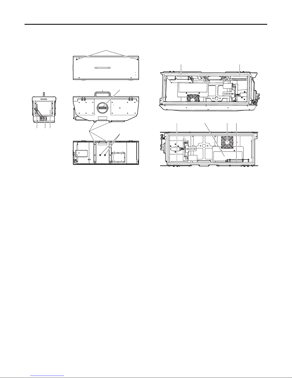
Housing unit
Camera housing control board
Connect the supplied camera cable.
Air filter
Air is taken in through the air filter. Replace it when it is
clogged up.
( Whenever the air filter needs replacement, ask the store
where you purchased the product to do the job.)
Top cover open/close bolts (2)
Loosen using the supplied Allen key, open the top cover.
Heater
When the controller’s H/F switch is at ON, the heater will
come on whenever the temperature inside the camera
housing drops.
Ventilating fan
When the controller’s H/F switch is at ON, the fan will
come on whenever the temperature inside the camera
housing rises.
Depending on the temperature, the fan operates at the
high or low setting.
Use the switch at the ON setting because a high
camera temperature will adversely affect the camera’s
performance.
Grip
Used to carry the camera housing.
I/F connector
Connect this to the I/F connector on the main unit.
Wiper blade
Replace the wiper blade when it can no longer wipe off
waterdrops well.
How to replace it: Raise the blade at the center, pull it up
and off, and fit a new blade in its place.
After replacing the blade, check that the
two rods holding the wiper blade are
parallel to the glass surface.
( Whenever the wiper blade needs
replacement, ask the store where you
purchased the product to do the job.)
Wiper unit
Used to wipe off waterdrops during or after a rain. The
wiper operates when the WIP switch on the controller is
pressed on.
Defroster
The anti-fogging heater is vapor-deposited. It turns on
when the controller’s DEF switch is set to ON, and it is
turned off by the thermo switch when the temperature
rises above the rating.
Housing mounting rails
Align the rails with the housing mount frame which is
installed on the rotary arm of the main unit, and slide the
housing along the rails.
Housing mounting screw holes (2)
Use these holes to secure the housing using the housing
securing bolts provided with the housing mount frame
which has been installed on the rotary arm of the main
unit.
<The inside of housing>
11
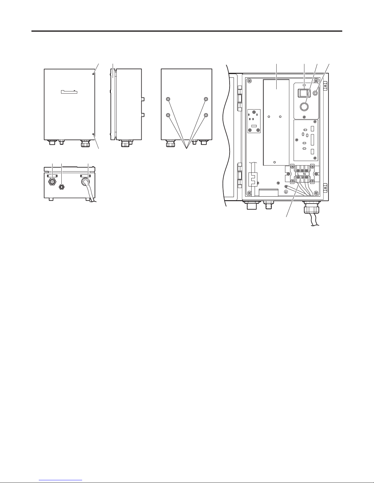
Parts and their functions
AC adapter unit
DC power unit
This unit supplies a DC output of 15 V, 10 A (maximum)
when an AC input of 120 V is supplied.
Power switch [POWER ON/OFF]
This switch is used to supply AC power to the DC power
unit. Keep the switch in the ON position during use.
Fuse holder/fuse
A fuse for protecting the DC power unit is in the fuse
holder. A burnt fuse may be caused by a DC power
unit defect. In such a case, consult the store where you
purchased it.
Power LED
This lights up red when the power switch is at ON.
This is off when the power switch
is at OFF.
Cover fastening screws (2)
To ensure safety, be absolutely sure to tighten up these
screws and close the cover upon completion of the
installation work.
Cover
Loosen the two cover fastening screws and open the
cover to proceed with the connections. When closing the
cover, first close the cover, and then be absolutely sure to
tighten up the two fastening screws.
Since malfunctions or other trouble may result if the
screws are not tightened enough, be absolutely sure to
use a screwdriver to tighten them up.
AC power input terminal board
This terminal board is for connecting AC input power.
(AC 120 V, 60 Hz, 120 W)
AC adapter mounting screw holes (×4)
Attach the supplied pole mounting plate to these screw
holes when the AC adapter is to be mounted on a pole or
other support.
DC output connector [DC15 V OUT]
Connect this connector to the [POWER] connector on the
main unit using the supplied power cable.
Ventilation opening
AC power input cable [AC IN]
This is the AC power input cable. It is held in place by the
fixed bushing.
<The inside of AC adapter>
12
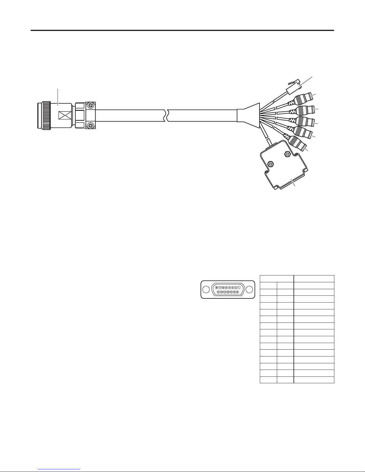
Parts and their functions
Supplied cable unit
24P round water-proof plug (male)
Connect this to the multi connector [MULTI] on the main
unit.
RJ-45 modular plug
Connect this to pan/tilt head controller.
It can be extended up to 3281 ft. (1000 m).
To extend the connection, use a relay adapter purchased
on the market and use a 10BASE-T straight cable (UTP
category 5) for the extension.
VIDEO OUT BNC jack
This is the output connector for the camera’s video
signals.
Use a BNC coaxial cable for the connecting cable.
Y OUT BNC jack
This is the output connector for the camera’s video
signals.
Use a BNC coaxial cable for the connecting cable.
Pr OUT BNC jack
This is the output connector for the camera’s video
signals.
Use a BNC coaxial cable for the connecting cable.
Pb OUT BNC jack
This is the output connector for the camera’s video
signals.
Use a BNC coaxial cable for the connecting cable.
G/L IN BNC jack
This is the gen-lock signal input jack.
Use a BNC coaxial cable for the connecting cable.
D-SUB 15P connector (male)
Connect the controller used for the multi purpose camera
to this connector. When connecting it directly, remove the
stud prior to use.
Pin No. Signal name
1 – – –
9 – – –
2 – – –
10 – – –
3 – – –
11 – – –
4 – – –
12 GND
5 – – –
13 TXD (C)
6 – – –
14 RXD (H)
7 TXD (H)
15 RXD (C)
8 – – –
<Multi cable> (VEEB0133)
13
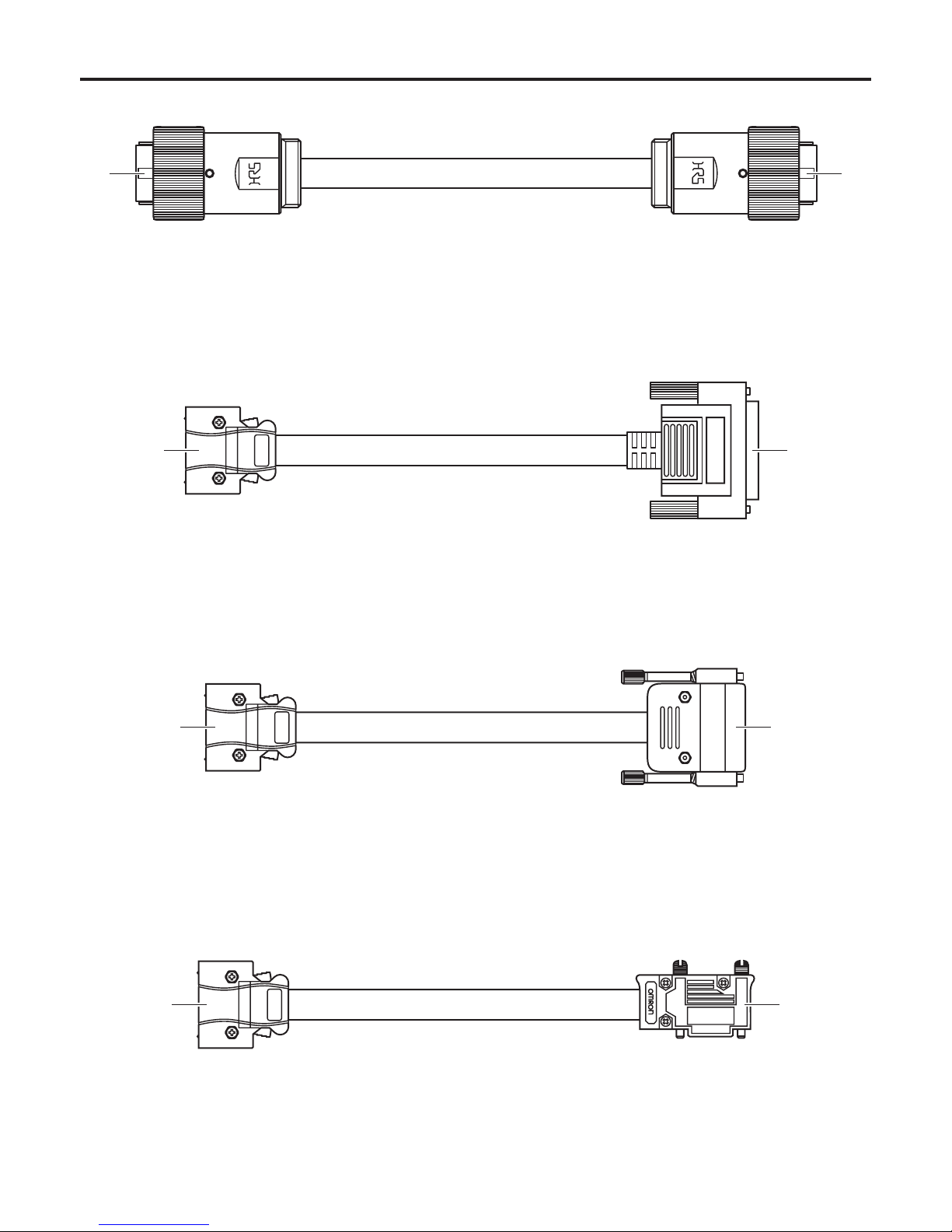
Parts and their functions
<Power cable> (VEEB0152)
7P round water-proof plug (female)
Connect this to the power connector [POWER] on the
main unit.
7P round water-proof plug (male)
Connect this to the DC output connector [DC 15V OUT]
on the AC adapter.
<Convertible camera cable> (VEEB0176)
26P connector (male)
Connect this to the CAMERA I/F connector [CAMERA
I/F] on the housing.
50P connector (male)
Connect this to the CAMERA I/F connector [CAMERA
I/F] on the convertible camera.
26P connector (male)
Connect this to the CAMERA I/F connector [CAMERA
I/F] on the housing.
D-SUB 15P connector (female)
Connect this to the I/F connector [CAMERA I/F] on the
AK-HC900 series.
<AK-HC900 series cable> (VEEB0177)
26P connector (male)
Connect this to the CAMERA I/F connector [CAMERA
I/F] on the housing.
High-density D-SUB 15P connector (male)
Connect this to the I/F connector [I/F] on the AK-HC1500.
<AK-HC1500 cable> (VEEB0178)
14
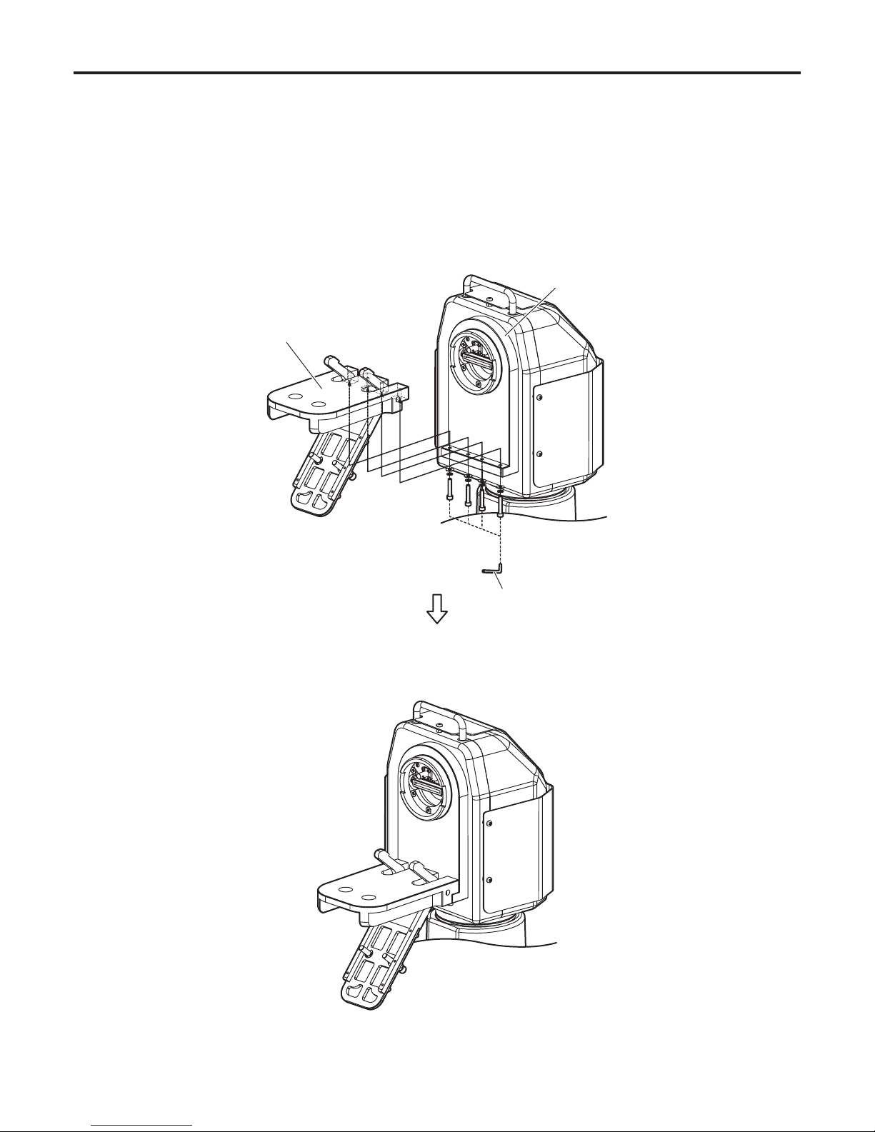
Installation
Installing the housing mount frame
Attach the housing mount frame (supplied) to the rotary arm of the main unit.
Attach the housing mount frame to the rotary arm as shown in the figure below. The screws must be installed together with
the flat washers and spring washers (supplied).
· Using the supplied Allen key, install the frame securely to prevent looseness in the four places where the screws are used.
Rotary arm
<Housing mount frame installed on rotary arm>
Allen key
Housing mount frame
 Loading...