

Panasonic aw-pb306 Operation Manual
Model AW- P
Before attempting to connect, operate or adjust this product, please read
these instructions completely.
Studio SDI Card
This product consists of an SDI card and an interface
bracket.
2
FCC Note:
This device complies with Part 15 of the FCC Rules.
To assure continued compliance follow the attached
installation instructions and do not make any
unauthorized modifications.
This equipment has been tested and found to comply
with the limits for a class A digital device, pursuant to
Part 15 of the FCC Rules. These limits are designed
to provide reasonable protection against harmful
interference when the equipment is operated in a
commercial environment. This equipment generates,
uses, and can radiate radio frequency energy and, if
not installed and used in accordance with the
instruction manual, may cause harmful interference to
radio communications. Operation of this equipment in
a residential area is likely to cause harmful
interference in which case the user will be required to
correct the interference at his own expense.
CAUTION
RISK OF ELECTRIC SHOCK
DO NOT OPEN
CAUTION: TO REDUCE THE RISK OF ELECTRIC SHOCK,
DO NOT REMOVE COVER (OR BACK).
NO USER SERVICEABLE PARTS INSIDE.
REFER TO SERVICING TO QUALIFIED SERVICE PERSONNEL.
The lightning flash with arrowhead symbol,
within an equilateral triangle, is intended to
alert the user to the presence of uninsulated
“dangerous voltage” within the product’s
enclosure that may be of sufficient magnitude
to constitute a risk of electric shock to
persons.
The exclamation point within an equilateral
triangle is intended to alert the user to the
presence of important operating and
maintenance (service) instructions in the
literature accompanying the appliance.
This Class A digital apparatus complies with Canadian
ICES-003.
Cet appareil numérique de la class A est conforme à
la norme NMB-003 du Canada.
For CANADA
indicates safety information.
WARNING:
TO REDUCE THE RISK OF FIRE OR SHOCK
HAZARD, DO NOT EXPOSE THIS
EQUIPMENT TO RAIN OR MOISTURE.
CAUTION:
TO REDUCE THE RISK OF FIRE OR SHOCK
HAZARD AND ANNOYING INTERFERENCE,
USE THE RECOMMENDED ACCESSORIES
ONLY.
CAUTION:
TO REDUCE THE RISK OF FIRE OR SHOCK
HAZARD, REFER MOUNTING OF THE
OPTIONAL INTERFACE BOARD TO
QUALIFIED SERVICE PERSONNEL.

3
Contents
Overview
Installing the SDI card in a convertible camera (such
as the AW-E300, AW-E600, AW-E800A) and
mounting the camera on the interface bracket makes
it possible for a viewfinder and/or intercommunications headset to be used and thus enable
the camera to be used as a studio camera.
It is also possible to output SDI signals which are
compliant with the SMPTE259M standard.
Features
O SDI signal output compliant with SMPTE259M
standard (max. 200 m using a BELDEN 9231
coaxial cable)
O An inter-communications headset can be used and
its volume adjusted
O Includes viewfinder STANDBY/ON switch
O Output signals (brightness and composite video
signals) to the viewfinder can be switched using the
menu settings
O Zebra pattern and safety zone displays appearing
in the viewfinder can be switched using the menu
settings
Operating precautions
Important
O This product consists of an SDI card and an
interface bracket.
The EVF I/F cable of the interface bracket must be
connected to the connector on the SDI card before
use. If this connection is not performed, signals will
not be output from the SDI card.
O When connecting or disconnecting a cable from any
unit, ensure that the power to that unit is turned off.
O Do not drop this product or subject it to strong
shock or vibration, as this may cause it to
malfunction.
O Avoid using the unit in very humid or dusty
locations, as this may cause it to malfunction.
O Avoid using the unit in locations where the
temperature is below freezing point or above 104°F
(40°C). Otherwise, the picture quality may
deteriorate or malfunctioning may result.
Overview . . . . . . . . . . . . . . . . . . . . . . . . . . . . . . . . . .3
Features . . . . . . . . . . . . . . . . . . . . . . . . . . . . . . . . . .3
Operating precautions . . . . . . . . . . . . . . . . . . . . . .3
Parts and their functions . . . . . . . . . . . . . . . . . . . .4
SDI card . . . . . . . . . . . . . . . . . . . . . . . . . . . . . . . . .4
Interface bracket . . . . . . . . . . . . . . . . . . . . . . . . . .4
Installing the SDI card . . . . . . . . . . . . . . . . . . . . . . .5
Interface bracket mountings . . . . . . . . . . . . . . . . . .6
Mounting the bracket on a tripod . . . . . . . . . . . . . .6
Mounting the camera . . . . . . . . . . . . . . . . . . . . . . .6
Mounting the viewfinder . . . . . . . . . . . . . . . . . . . . .6
Connections . . . . . . . . . . . . . . . . . . . . . . . . . . . . . . .7
Connected components . . . . . . . . . . . . . . . . . . . . .7
Setting and changing of menu items . . . . . . . . . . .8
Performing the settings . . . . . . . . . . . . . . . . . . . . .8
Optional card settings submenu . . . . . . . . . . . . . .9
Specifications . . . . . . . . . . . . . . . . . . . . . . . . . . . .10
4
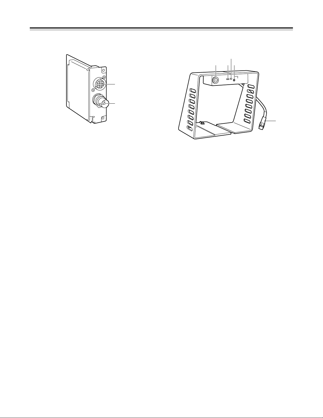
$ SDI card $ Interface bracket
1 EVF I/F connector
The EVF I/F cable 7 from the interface bracket is
connected here.
If the EVF I/F cable is not connected, signals will
not be output from the SDI card.
2 SDI OUT connector
SDI signals are output from here.
3 EVF connector
The viewfinder (such as the WV-VF65B or AWVF80) is connected here.
4 EVF standby switch
ST.BY.
: Places the viewfinder in standby mode.
ON
: Outputs images to the viewfinder.
5 Inter-communications level control
This adjusts the sound level output to the intercommunications headset.
6 Inter-communications jack,
plug type: 1/8˝ (3.5 mm)
The inter-communications headset is connected
here.
If the plug diameter does not match, use the
adjuster plug supplied with this product.
1/4˝ 5 1/8˝ (6.35 mm 5 3.5 mm)
7 EVF I/F cable
This is connected to the EVF I/F connector 1 on
the SDI card.
Parts and their functions
EVF I/F
SDI OUT
2
1
INCOM
ST. BY ON
LEVEL
7
3 4 6
5
 Loading...