

Page 1
ENGLISHITALIANO
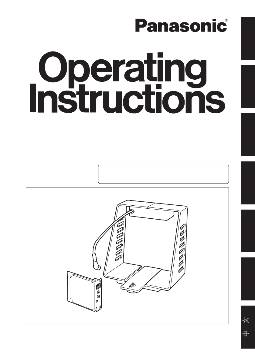
Studio Card
AW-PB305AL
This product consists of an studio card and an
interface bracket.
FRANÇAIS DEUTSCH
ESPAÑOL
РУССКИЙ
Before attempting to connect, operate or adjust this product,
please read these instructions completely.
中 文
Page 2
ENGLISH VERSION
Safety precautions
DO NOT REMOVE PANEL COVERS BY UNSCREWING.
To reduce the risk of electric shock, do not remove the covers. No user serviceable
parts inside.
Refer servicing to qualified service personnel.
WARNING:
• TO REDUCE THE RISK OF FIRE OR SHOCK HAZARD, DO NOT EXPOSE
THIS EQUIPMENT TO RAIN OR MOISTURE.
• TO REDUCE THE RISK OF FIRE OR SHOCK HAZARD, KEEP THIS
EQUIPMENT AWAY FROM ALL LIQUIDS. USE AND STORE ONLY IN
LOCATIONS WHICH ARE NOT EXPOSED TO THE RISK OF DRIPPING OR
SPLASHING LIQUIDS, AND DO NOT PLACE ANY LIQUID CONTAINERS ON
TOP OF THE EQUIPMENT.
CAUTION:
TO REDUCE THE RISK OF FIRE OR SHOCK HAZARD AND ANNOYING
INTERFERENCE, USE THE RECOMMENDED ACCESSORIES ONLY.
CAUTION:
TO REDUCE THE RISK OF FIRE OR SHOCK HAZARD, REFER CHANGES OF
SWITCH SETTINGS INSIDE THE UNIT TO QUALIFIED SERVICE PERSONNEL.
indicates safety information.
- 1 (E) -
Page 3
Information on Disposal for Users of Waste Electrical & Electronic
Equipment (private households)
This symbol on the products and/or accompanying documents
means that used electrical and electronic products should not be
mixed with general household waste.
For proper treatment, recovery and recycling, please take these
products to designated collection points, where they will be accepted
on a free of charge basis. Alternatively, in some countries you may
be able to return your products to your local retailer upon the purchase of an
equivalent new product.
Disposing of this product correctly will help to save valuable resources and prevent
any potential negative effects on human health and the environment which could
otherwise arise from inappropriate waste handling.
Please contact your local authority for further details of your nearest designated
collection point.
Penalties may be applicable for incorrect disposal of this waste, in accordance with
national legislation.
For business users in the European Union
If you wish to discard electrical and electronic equipment, please contact your
dealer or supplier for further information.
Information on Disposal in other Countries outside the European
Union
This symbol is only valid in the European Union.
If you wish to discard this product, please contact your local authorities or dealer
and ask for the correct method of disposal.
ENGLISH
- 2 (E) -
Page 4

Contents
Configuration ........................................ 3
Accessories .......................................... 3
Introduction ........................................... 4
Characteristics ...................................... 4
Precautions for use .............................. 4
Major operating controls and
their functions ................................. 5
Studio card ....................................... 5
Interface bracket .............................. 6
Installing the studio card ..................... 7
Interface bracket mountings ............... 8
Mounting the bracket on a tripod ..... 8
Mounting the camera ....................... 8
Mounting the viewfinder
on a bracket .................................. 8
Configuration
Studio card (AW-PB305A U01) ............. 1
Interface bracket (AW-PB305A U02) .... 1
Connections .......................................... 9
When configuring a system
with the remote control unit ......... 9
When configuring a system
with the remote operation panel
Setting and changing of menu items
Performing the settings .................. 11
Optional card settings submenu .... 13
Appearance ......................................... 14
Studio card ..................................... 14
Interface bracket ............................ 15
Specifications ..................................... 16
... 10
... 11
Accessories
Adjuster plug (M6 M3) ........................ 1
Screws (6 mm) ....................................... 2
Screws (8 mm) ....................................... 4
- 3 (E) -
Page 5
Introduction
Installing the studio card in a convertible
camera (such as the AW-E350, AW-E650,
AW-E655, AW-E750 and AW-E860) and
mounting the camera on the interface
bracket makes it possible for a viewfinder
and/or inter-communications headset to
be used and thus enable the camera to be
used as a studio camera.
Characteristics
An inter-communications headset can be
used and its volume adjusted.
The STANDBY/ON switch function of
the viewfinder (WV-VF65B, AW-VF80) is
incorporated.
Output signals (brightness and
composite video signals) to the
viewfinder can be switched using the
menu settings.
Notes
The AW-PB305A cannot be installed
to the following models;
AW-RP605, AW-PB605
When the studio card unit is to be
discarded at the end of its service
life, ask a specialized contractor
to dispose of it properly in order to
protect the environment.
Zebra pattern and safety zone displays
appearing in the viewfinder can be
switched using the menu settings.
The VIDEO ON/OFF switch function of
the viewfinder (AW-VF64) is incorporated.
( In order to prevent CRT burn-in, the
AW-VF64 does not come with a standby
function.)
ENGLISH
Precautions for use
When connecting or disconnecting a
cable from any unit, ensure that the
power to that unit is turned off.
Do not drop this product or subject it to
strong shock or vibration, as this may
cause it to malfunction.
- 4 (E) -
Avoid using the unit in very humid or
dusty locations, as this may cause it to
malfunction.
Avoid using the product at a cold place
below –10°C or at a hot place above
+45°C because extremely low or high
temperature will adversely affect the
parts inside.
Page 6
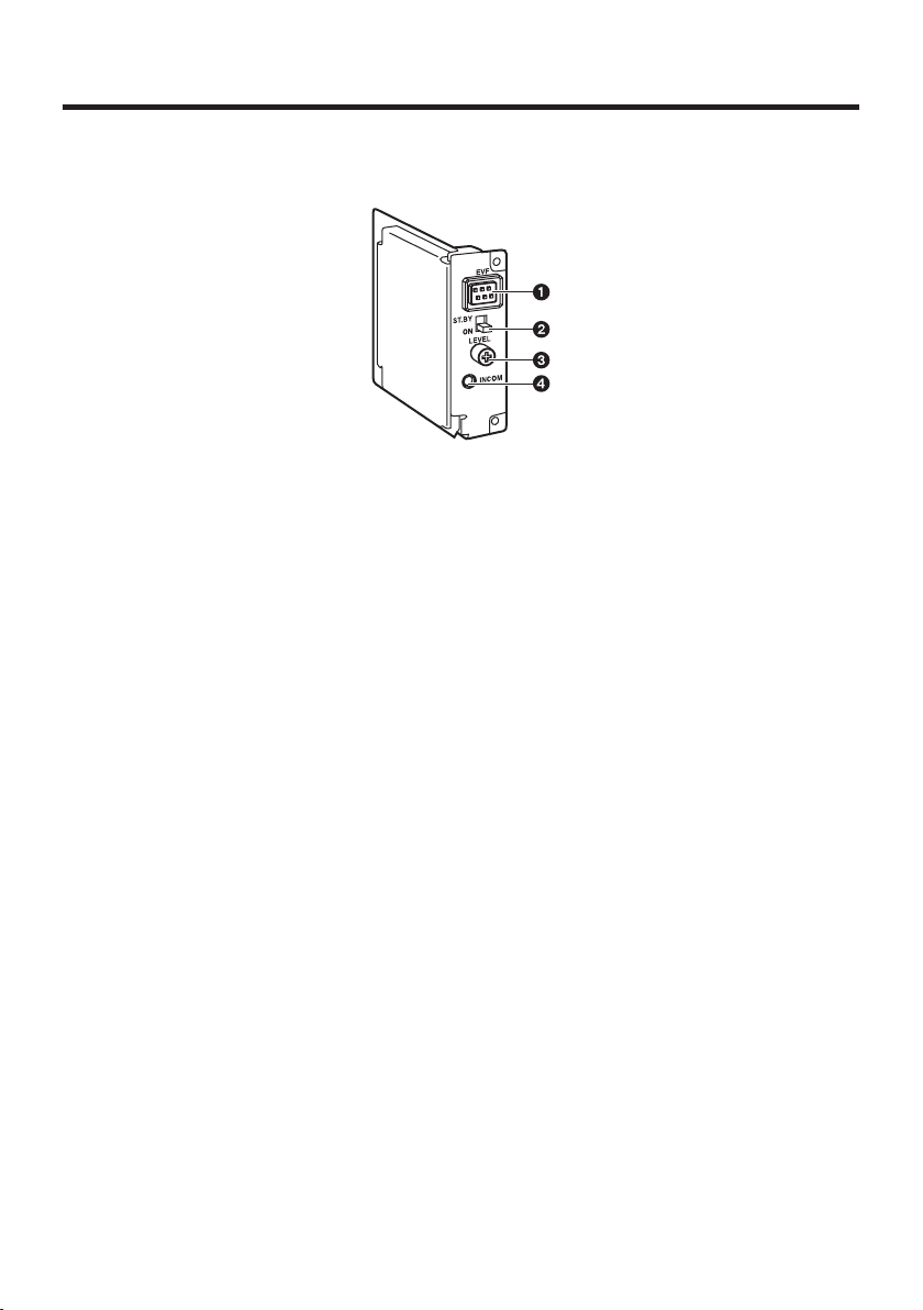
Major operating controls and their functions
Studio card
EVF connector [EVF]
The EVF cable 7 from the interface
bracket is connected here.
2 EVF standby / VIDEO ON/OFF
switch
[ST.BY / VIDEO ON/OFF]
<For the WV-VF65B, AW-VF80>
ST.BY:
ON:
<For the AW-VF64>
VIDEO ON: Outputs images to the
VIDEO OFF: No images appear on the
The AW-VF64 does not come with a
3
Inter-communications level control
Places the viewfinder in standby
mode.
Outputs images to the viewfinder.
viewfinder.
viewfinder.
standby function.
[LEVEL]
This adjusts the sound level output to
the inter-communications headset.
4 Inter-communications jack (M3)
[INCOM]
The inter-communications headset is
connected here.
If the plug diameter does not match, use
the adjuster plug (M6 M3) supplied
with this product.
MIC: Dynamic (With Preamp)
50 /–20 dB
Receiver: 150 (max. 200 mW)
- 5 (E) -
Page 7

Major operating controls and their functions
Interface bracket
ENGLISH
5 EVF connector 1 [EVF1]
The viewfinder (WV-VF65B, AW-VF80)
is connected here.
6 EVF connector 2 [EVF2]
The viewfinder AW-VF64 is connected
here.
Note
Do not connect EVFs to EVF
connectors 1 and 2 (
the same time.
5 and 6) at
7 EVF cable
This is connected to the EVF connector
on the studio card.
8 TALLY input connector [TALLY IN]
This is the tally control external input
connector.
OPEN: TALLY OFF
SHORT:
When using the AW-CB400 remote
operation panel and AW-CA50T8G
control cable for connecting to the
convertible camera, connect the TALLY
cable of the AW-CA50T8G to this
connector.
TALLY ON
- 6 (E) -
Page 8

Installing the studio card
Always ask your local dealer to install the studio card.
Before installing the studio card:
Release the static carried in the body of the person to perform the installation.
Installation can be performed more safely if an anti-static wrist strap is worn.
Touching the card without first releasing this static may cause malfunctioning.
Do not allow the metal part of the card come in contact with any other metal parts.
Rear panel
Optional card
slot cover
Studio card
2 screws (6 mm)
1
Turn the power to the camera off
and remove any cables which are
connected to the power connector or
other connectors.
2
Loosen the 4 screws (8 mm) on the
rear panel of the camera, then remove
the panel itself.
3
Loosen the 2 screws (6 mm) on the
optional card slot cover, then remove
the cover.
4
Align the studio card with the guides
and insert it.
Ensure the card is fully inserted.
4 screws (8 mm)
5
Firmly tighten the 2 screws (6 mm) to
the optional card slot.
6
Firmly secure the rear panel with the
4 screws (8 mm).
Note
If the screws are misplaced, use
the extra screws supplied with this
product.
- 7 (E) -
Page 9

Interface bracket mountings
Mounting the bracket
on a tripod
1
Mount the interface bracket on the
tripod. (Screw: 1/4 – 20UNC)
Mounting the camera
2
Mount the camera (in which the
studio card has been installed) on the
interface bracket.
Fasten the fixing knob to firmly secure
the camera.
Mounting the viewfinder
on a bracket
3
Mount the mounting base that is
supplied to the viewfinder onto the top
of the interface bracket using the 2
screws provided.
( Mount the base securely so that it is
not unsteady.)
Mounting base
2 screws
4
Slide the viewfinder onto the mounting
base and tighten the fixing knob to
secure it firmly.
5
Connect the viewfinder cable to the
EVF connector 1 or 2 on the interface
bracket.
6
Connect the EVF cable from the
interface bracket to the EVF connector
on the studio card.
ENGLISH
Fixing knob
< WV-VF65B,
AW-VF80, etc.>
Fixing knob
Fixing knob
<AW-VF64>
- 8 (E) -
Page 10

Connections
When configuring a system with the remote control unit
Convertible camera:
AW-E350, AW-E650, AW-E655,
AW-E750, AW-E860, etc.
Viewfinder:
WV-VF65B, AW-VF80, AW-VF64, etc.
Remote control unit (RCU):
WV-RC700A, WV-RC550, AW-RC600,
etc.
Viewfinder:
WV-VF65B, AW-VF80,
AW-VF64, etc.
Inter-communications headset
Video monitor
Use the RCU cable (AW-CA50A26) to
connect the remote control unit to the
convertible camera.
Power to the camera is supplied from the
remote control unit.
Convertible camera:
AW-E350, AW-E650, AW-E655,
AW-E750, AW-E860, etc.
Inter-communications headset
Video monitor
Composite signals
Coaxial cable
Inter-communications headset
Remote control unit (RCU):
WV-RC700A, WV-RC550,
AW-RC600, etc.
RCU cable:
AW-CA50A26
- 9 (E) -
Page 11

Connections
When configuring a system with the remote operation panel
Convertible camera:
AW-E350, AW-E650, AW-E655,
AW-E750, AW-E860, etc.
Viewfinder:
WV-VF65B, AW-VF80, AW-VF64, etc.
Remote operation panel:
AW-CB400, etc.
Video monitor
Viewfinder:
WV-VF65B, AW-VF80,
AW-VF64, etc.
Use the control cable (AW-CA50T8G) to
connect the remote operation panel to
the convertible camera.
Use the AW-PS505A AC adapter, which
is an optional accessory, for the power
supply.
Inter-communication between the
remote operation panel and studio card
is not possible.
TALLY cable
Convertible camera:
AW-E350, AW-E650,
AW-E655, AW-E750,
AW-E860, etc.
ENGLISH
AC adapter:
AW-PS505A
Video monitor
Cable provided
with AC adapter
Cable provided with AC adapter
AC adapter:
AW-PS505A
- 10 (E) -
Remote operation
panel:
AW-CB400, etc.
10BASE-T
straight cable
Control cable:
AW-CA50T8G
Page 12

Setting and changing of menu items
Camera settings to match the system configuration and filming conditions can be made
using the menu screens.
See the convertible camera operating instructions for more information on the settings.
For details on the setting procedures when the remote control unit and remote operation
panel are used, refer to the operating instructions of the unit and panel.
Performing the settings
1
Display the main menu.
When performing the settings with
the convertible camera:
Press the MENU switch continuously
for at least 5 seconds.
When performing the settings with
the remote control unit (AW-RC600):
Set the MENU switch to “ON”.
Main menu for halogen light mode,
fluorescent light mode and outdoor mode
The mode selected is displayed here.
To return to filming mode
( This is displayed when the convertible
camera is used to perform the settings.)
Main menu for user mode
* “Option Card 2” is displayed on the
menu when the optional card has been
plugged into the optional card slot of
the additional card box.
Convertible camera
MENU switch
ITEM/AWC switch
YES/ABC switch
NO/BAR switch
Remote control unit (AW-RC600)
MENU switch
- 11 (E) -
ITEM UP switch
ITEM DOWN switch
DATA YES/UP switch
DATA NO/DOWN switch
Page 13

Setting and changing of menu items
2
Select “Option Card 1” to display the
submenu.
When performing the settings with
the convertible camera:
Press the MENU or ITEM/AWC
switch to move the flashing to the
setting item, then press the YES/ABC
switch to display the submenu.
When performing the settings with
the remote control unit (AW-RC600):
Press the ITEM UP or ITEM DOWN
switch to move the flashing to the
setting item, then press the DATA
YES/UP switch to display the
submenu.
3
Select the setting item and change the
setting.
When performing the settings with
the convertible camera:
Press the MENU or ITEM/AWC
switch to move the flashing to the
desired setting item, then press
the YES/ABC or NO/BAR switch to
change the setting.
When performing the settings with
the remote control unit (AW-RC600):
Press the ITEM UP or ITEM DOWN
switch to move the flashing to the
desired setting item, then press the
DATA YES/UP or DATA NO/DOWN
switch to change the setting.
4
Return to filming mode.
When performing the settings with
the convertible camera:
Press the MENU or ITEM/AWC
switch and select “End” on the main
menu, then press the YES/ABC
switch.
When performing the settings with
the remote control unit (AW-RC600):
Set the MENU switch to “OFF”.
After being returned to filming mode,
the convertible camera will operate as
per the changed settings.
ENGLISH
- 12 (E) -
Page 14

Setting and changing of menu items
Optional card settings submenu
3 Safety zone (1 to 4, OFF)
2
3
4
Zebra indicator (ON, OFF)
This sets the zebra pattern display
which appears in the viewfinder.
ON: Zebra patterns are displayed in
the viewfinder.
OFF: Zebra patterns are not displayed
in the viewfinder.
<Note>
Even if “ON” is selected for this setting,
the zebra patterns will not be displayed
in the viewfinder if “CVBS” has been
selected as the EVF output 4 setting.
This selects the type of safety zone that
is displayed in the viewfinder.
If “OFF” is selected, a safety zone will
not be displayed.
<Note>
The safety zone and the center marker
reflect the electrical positions which may
differ from the optical positions.
The inner frame and the outer frame
are approximately 90% and 95%,
respectively, of the safety zone.
2 Level (70% to 110%)
The zebra patterns are displayed to use
as a yardstick for the brightness level.
<Note>
These settings are available when
“ON” has been selected for the Zebra
indicator setting.
4 EVF output (Y, CVBS)
This sets the signals to be output to the
viewfinder.
Y: Brightness signals are output to
the viewfinder.
CVBS: Color signals are output to the
viewfinder.
<Note>
The zebra pattern is not displayed in
the viewfinder when “CVBS” has been
selected.
- 13 (E) -
Page 15

Appearance
Studio card
91
21.5
Unit: mm
ENGLISH
96
- 14 (E) -
70
Page 16

Appearance
Interface bracket
190
Unit: mm
50
183
141 30
- 15 (E) -
Page 17

Specifications
Power requirements: DC 12 V (supplied from convertible camera)
Power consumption: 15 W (When WV-VF65B, AW-VF80 is connected)
indicates safety information.
Ambient operating temperature: –10°C to +45°C
Ambient operating humidity: 30% to 90% (without condensation)
Dimensions (WHD):
Studio card 21.57091 mm (excluding protrusions)
Interface bracket 190183171 mm (excluding protrusions)
Weight:
Studio card 0.08 kg
Interface bracket 0.94 kg
Input/output connectors:
Studio card
EVF connector 6-pin, square
Inter-communications jack M3
Interface bracket
EVF connector 1
EVF connector 2 6-pin, round, composite signals/brightness, 1.0 V [P-P]
TALLY input connector BNC
Switch/control functions:
Studio card
WV-VF65B, AW-VF80 ST.BY/ON
AW-VF64 VIDEO ON/VIDEO OFF
Inter-communications level control
Menu screens
Level (70% to 110%)
Safety zone (1/2/3/4/5/OFF)
EVF output (Y/CVBS)
10-pin, round, composite signals/brightness, 1.0 V [P-P]
EVF standby / VIDEO ON/OFF switch
Zebra indicator (ON/OFF)
ENGLISH
Weight and dimensions indicated above are approximate.
Specifications are subject to change without notice.
- 16 (E) -
 Loading...