

Page 1
AK-MSU930P
Before attempting to connect, operate or adjust this product, please read these
instructions completely.
Master Setup Unit
Page 2
2
Safety precautions
CAUTION
RISK OF ELECTRIC SHOCK
DO NOT OPEN
CAUTION: TO REDUCE THE RISK OF ELECTRIC SHOCK,
DO NOT REMOVE COVER (OR BACK).
NO USER SERVICEABLE PARTS INSIDE.
REFER SERVICING TO QUALIFIED SERVICE PERSONNEL.
The lightning flash with arrowhead symbol,
within an equilateral triangle, is intended to
alert the user to the presence of uninsulated
“dangerous voltage” within the product’s
enclosure that may be of sufficient magnitude
to constitute a risk of electric shock to
persons.
The exclamation point within an equilateral
triangle is intended to alert the user to the
presence of important operating and
maintenance (service) instructions in the
literature accompanying the appliance.
WARNING:
TO REDUCE THE RISK OF FIRE OR SHOCK
HAZARD, DO NOT EXPOSE THIS
EQUIPMENT TO RAIN OR MOISTURE.
This class A digital apparatus complies with
Canadian ICES-003.
Cet appareil numérique de la classe A est
conforme à la norme NMB-003 du Canada.
CAUTION:
TO REDUCE THE RISK OF FIRE OR SHOCK
HAZARD AND ANNOYING INTERFERENCE,
USE ONLY THE RECOMMENDED
ACCESSORIES.
The serial number of this product may be
found on the bottom of the unit.
FCC Note:
This device complies with Part 15 of the FCC Rules.
To assure continued compliance follow the attached
installation instructions and do not make any
unauthorized modifications.
This equipment has been tested and found to comply
with the limits for a class A digital device, pursuant to
Part 15 of the FCC Rules. These limits are designed
to provide reasonable protection against harmful
interference when the equipment is operated in a
commercial environment. This equipment generates,
uses, and can radiate radio frequency energy and, if
not installed and used in accordance with the
instruction manual, may cause harmful interference to
radio communications. Operation of this equipment in
a residential area is likely to cause harmful
interference in which case the user will be required to
correct the interference at their own expense.
indicates safety information.
For CANADA
Page 3

3
Operating precautions
≥ Use the AW-PS505 dedicated AC adapter for the MSU’s power supply.
≥≥
Handle the unit carefully.
Dropping the unit or subjecting it to strong impact may cause malfunctioning and failures.
≥ Operate the unit within a temperature range of 32 °F to 104 °F (0 °C to 40 °C).
Operation in locations below 32 °F or above 104 °F may adversely affect the internal parts.
≥ Be absolutely sure to turn off the power before connecting or disconnecting the cables.
≥ Do not use the unit outdoors.
≥ Install the unit at a distance of at least 1 meter from the monitor.
≥ Maintenance
Disconnect the power plug, and wipe the unit with a dry cloth. To remove stubborn dirt, soak a cloth in some diluted
kitchen detergent and wring it out well, and then wipe the unit gently.
Contents ............................................................................................................................................................. 3
Overview ............................................................................................................................................................. 3
Accessories ........................................................................................................................................................ 3
Operating precautions ....................................................................................................................................... 3
Parts and their functions ................................................................................................................................... 4
Connections ..................................................................................................................................................... 14
External dimension drawing ........................................................................................................................... 14
Specifications ................................................................................................................................................... 15
≥This master setup unit (MSU) is used to control the the multi-format cameras (AK-HC931P) and the camera
control units (AK-HCU931P).
≥A dedicated multi-cable is used to connect this unit with the remote operation panel.
Overview
Accessories
Mounting screws (M4, 8 mm) ................................ a4
Thank you very much for purchasing this master setup unit.
Contents
≥≥
Avoid using benzine, paint thinners and other volatile substances.
≥≥
If a chemically-treated cleaning cloth is to be used, read the precautions for its use carefully.
Caution
Page 4
4
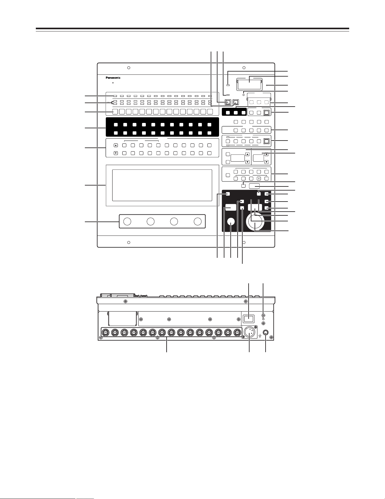
Parts and their functions
CABLE
TALLY
CAMERA
1
5600K
BLACK WHITE R B G GAMMA MATRIX FUNC SYSTEM
OFF
FLARE
GAMMA ON
BLK
OFF
GAMMA
BLK
PED GAIN GAMMA FLARE W. CLIP KNEE HD. DTL SD. DTL SD. SKINHD.SKIN
SHADING
OFF
KNEE
OFFOFF
HD. DTL SD. DTL
ON
HD. SKINONSD. SKIN
CLIP OFF
WHITE
OFF
MATRIX CHARACTER
CARD
HEAD POWER
ALL
CLOSE BAR TEST
WHITE
BLACK
SET UP
RESET
ALARM
REF
LOCAL
STORE
ALL
STORE
ON
MODE
CONTROL
23456789101112131415
SD CARD
AUTO
ON
SYNCRO
HEAD
CALL
ACTIVE
M-PED IRIS
AUTO
LENS EXT X0. 8
COASER
MEMO
RECALL
MEMO
RECALL
CAP 100 25ND6.3 1.6
3.2 4.3 6.3 DF0
RGBSEC
12
STORE
34
ENC
MONITOR
SCENE FILE
SHUTTER/SYNCRO
M-GAIN
REF FILE
5678
CC
1
2
3
4
7
5
6
8
9:
;
<
=
>
?
@
A
B
D
E
F
G
H
I
K
M
N
O
P
Q
ST
U
L
J
R
C
UNDO
POWER
Master Setup Unit
AUX
LINK
CSU
151413121110987654321
POWER
DC IN
G N D
W
X
Y
Z
V
MSU operation panel
1 Alarm LEDs [ALARM]
These LEDs light when optical transmission is not
proceeding satisfactorily or when a problem has occurred
in the camera, CCU fan or power supply.
Lighted green: Normal
Lighted orange: Head fan OFF, 3 dB optical level
margin
Lighted red: Cable trouble, 0 dB optical level
margin
Off: Failure to connect CCU, CCU power
OFF
2 Tally LEDs [TALLY]
The LEDs in the top row are the red tally indicators, and
the LEDs in the bottom row are the green tally indicators.
The tally LEDs are aligned in the numerical order of the
camera numbers.
Page 5

5
Parts and their functions
3 Camera selector switches [CAMERA]
These are used to select one camera and one CCU as
the pair which is to be controlled by the MSU.
A camera is selected by pressing the camera selector
switch with the same number as the camera to be
selected (its lamp will light). The selection is released by
pressing the camera selector switch of the selected
camera (its lamp will turn off).
When a camera selector switch is pressed, the MSU
settings (such as the switch lamp lighting and selection)
are performed using the information on the settings for
the camera concerned.
The details of the functions given below apply when one
or more camera selector switches have been selected.
4 MODE ON/OFF switches
These switches are for setting the camera operation
modes. The modes corresponding to the switches with
the lighted lamps are selected.
5600K switch [5600K MODE]
This is used to change the amplification rate of the GBR
signals by an electrical circuit to achieve the white
balance that corresponds to the color temperature of
5600K. When it is pressed, the B video signal is
attenuated by approximately -6 dB, the R video signal is
boosted by approximately 3 dB, and the G video signal is
not attenuated. Select this switch when shooting under a
5600K light source or shooting outdoors.
Lighted: 5600K
Off: 3200K
Flare switch [FLARE OFF MODE]
This is used to cancel the flare correction function (which
suppresses the rise of the pedestal in proportion to the
light quantity).
Lighted: Flare correction OFF (flare correction function
is canceled)
Off: Flare correction function is valid.
Black gamma ON switch [BLACK GAMMA ON MODE]
This is used to enable the black gamma function (which
changes the video signal amplification rate in parts where
the light quantity is low).
Lighted: Black gamma ON (black gamma function is
valid)
Off: Black gamma function is canceled.
Gamma OFF switch [GAMMA OFF MODE]
This is used to cancel the gamma correction function
(which provides the signal level of the video signals with
the reverse characteristics matching the TV video signal
input and light-emitting level characteristics).
Lighted: Gamma correction OFF (gamma correction
function is canceled)
Off: Gamma correction function is valid.
Knee OFF switch [KNEE OFF MODE]
This is used to cancel the knee function that attenuates
those parts of the video signals where a particular level
(knee point) has been exceeded so that they will not
become saturated as easily.
Lighted: Knee OFF (knee function is canceled)
Off: Knee function is valid.
White clip OFF switch [WHITE CLIP OFF MODE]
This is used to cancel the white clip function by which the
video signal output is clipped (saturated).
Lighted: White clip OFF (white clip OFF function is valid)
Off: White clip ON
Matrix ON switch [MATRIX ON MODE]
This is used to enable the matrix function by which the
chroma saturation is compensated for the G (green), B
(blue), R (red), Ye (yellow), Cy (cyan) and Mg (magenta)
signals and by which the chroma saturation and hue are
compensated for the I (skin tone) signals.
Lighted: Matrix ON (color correction function is valid)
Off: Matrix OFF
PM character display switch [CHARACTER]
This is used to set the characters to be displayed on the
PM to ON or OFF.
HDTV detail OFF switch [HD.DTL OFF MODE]
This is used to cancel the detail enhancer function that
enhances (adjusts the relative hardness/softness of) the
picture quality in the detailed parts of the HDTV video
output.
Lighted: Detail enhancer OFF (function for enhancing
picture quality in detailed parts canceled)
Off: Detail enhancer ON
SDTV detail OFF switch [SD.DTL OFF MODE]
This is used to cancel the detail enhancer function that
enhances (adjusts the relative hardness/softness of) the
picture quality in the detailed parts of the SDTV video
output.
Lighted: Detail enhancer OFF (function for enhancing
picture quality in detailed parts canceled)
Off: Detail enhancer ON
HDTV skin tone detail ON switch [HD SKIN ON MODE]
This is used to suppress the detail in the skin color parts
of the HDTV video output.
SDTV skin tone detail ON switch [SD SKIN ON MODE]
This is used to suppress the detail in the skin color parts
of the SDTV video output.
Page 6
6
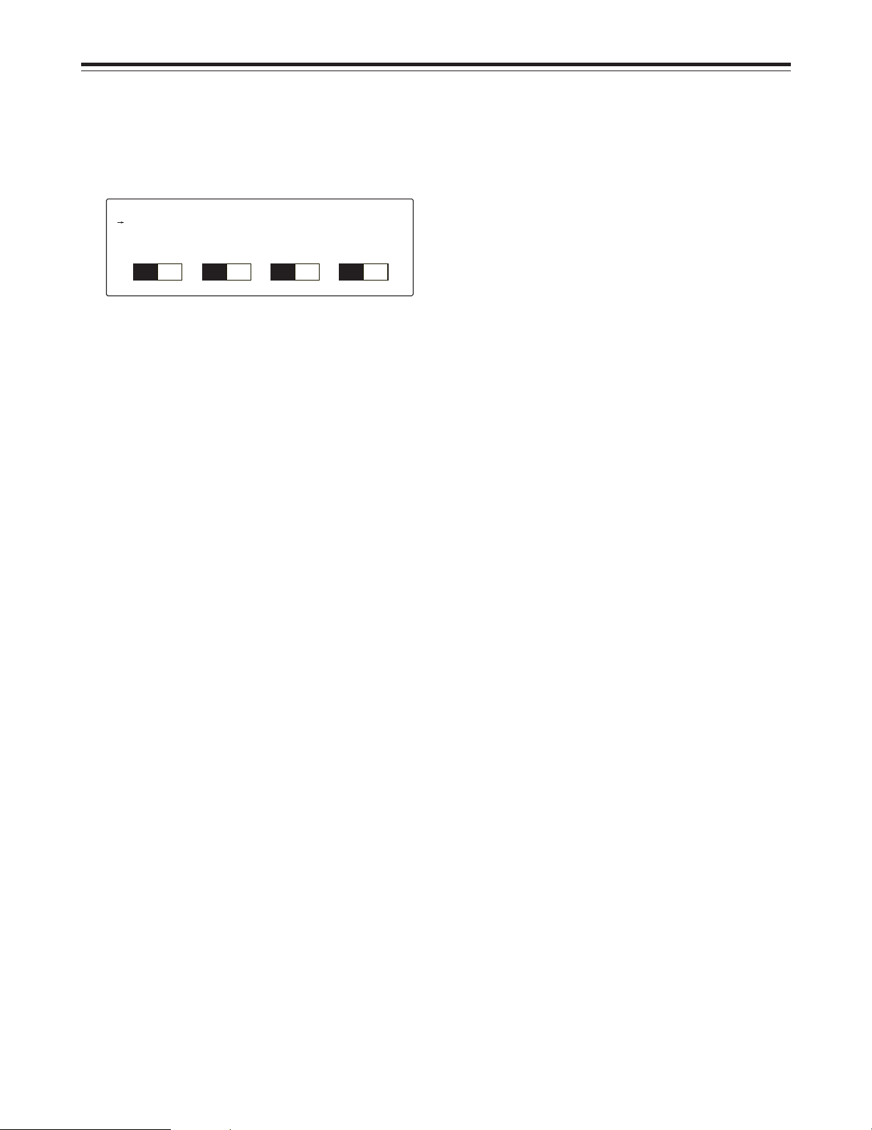
5 EL display
When the control item selector switches are selected, the
corresponding adjustment items and adjustment values
appear on the EL display.
Example of EL display
Parts and their functions
<HD DETAIL>
H DTL
LEVEL DEP
+ CLIP
H DTL
15
V DTL
DARK DTL
– CLIP
V DTL
16
CRISP
CORNER
CRISP
7
PEAK FREQ
PEAK FREQ
4
Black shading selector switch
[BLACK SHADING CONTROL]
This is used to correct the black shading (the coloring of
black images). When it is pressed (its lamp is lighted)
and when one of the SHADING R, G or B switches is
then pressed and selected, the adjustment items for the
black shading appear on the LCD display. The black
shading correction can be adjusted using the four
neighboring adjustment rotary encoders.
HSAW: Horizontal sawtooth wave correction
This is used to correct the coloring of black
screen images in the horizontal direction.
Adjustment range: –100 to 100
HPAR: Horizontal parabola correction
This is used to correct the coloring of black
screen images in the horizontal direction.
Adjustment range: –100 to 100
VSAW: Vertical sawtooth wave correction
This is used to correct the coloring of black
screen images in the vertical direction.
Adjustment range: –100 to 100
VPAR: Vertical parabola correction
This is used to correct the coloring of black
screen images in the vertical direction.
Adjustment range: –100 to 100
White shading selector switch
[WHITE SHADING CONTROL]
This is used to correct the white shading. When it is
pressed and its lamp is lighted and when one of the
SHADING R, G or B switches is then pressed and
selected, the adjustment items for the white shading
appear on the LCD display. The white shading correction
can be adjusted using the four neighboring adjustment
rotary encoders.
HSAW: Horizontal sawtooth wave correction
This is used to correct the coloring of white
screen images in the horizontal direction.
Adjustment range: –100 to 100
(0: Equivalent to OFF)
HPAR: Horizontal parabola correction
This is used to correct the coloring of white
screen images in the horizontal direction.
Adjustment range: –100 to 100
(0: Equivalent to OFF)
VSAW: Vertical sawtooth wave correction
This is used to correct the coloring of white
screen images in the vertical direction.
Adjustment range: –100 to 100
(0: Equivalent to OFF)
VPAR: Vertical parabola correction
This is used to correct the coloring of white
screen images in the vertical direction.
Adjustment range: –100 to 100
(0: Equivalent to OFF)
R, G, B shading switches [R, G, B]
These are used to select the video signals targeted for
shading correction from among the R, G and B signals.
The lamp of the selected switch lights.
The HD DETAIL switch will now be used as an example
to describe the EL menu.
When the HD.DTL control item selector switch is
pressed, what is shown in the example in the figure
above appears on the EL display.
The adjustment item title appears on the first line. On
lines 2, 3 and 4 are the adjustment item groups which
can be selected each time an individual adjustment item
is set. At the far left is the > arrow that indicates the
adjustment item group now selected; on the third tier from
the bottom is the adjustment item which has been
selected; on the second tier from the bottom is the
adjustment value level display; and on the bottom tier is
the adjustment value itself.
To select an adjustment item group, press the $ or #
switch to move the > arrow to the far left of the line with
the adjustment item group to be selected.
Once the adjustment item to be selected is displayed,
turn the adjustment rotary encoder to set the adjustment
value. To return (initialize) the changed data to the
original data, press the UNDO switch.
If a control switch is pressed and its lamp is turned off or
if another control switch is pressed and the menu screen
has changed, the setting of the adjustment item so far will
be stored.
6 Adjustment rotary encoders
The data of an adjustment item shown on the EL display
can be changed using the neighboring adjustment rotary
encoder.
7 Control item selector switches
When these switches are selected (their lamps are
lighted), the corresponding adjustment items and
adjustment values appear on the EL display. The
adjustment values can be changed using the neighboring
adjustment rotary encoder.
Undo switch [UNDO]
This is used to return the values controlled on the display
to the statuses that existed prior to the control.
Flare OFF switch [FLARE OFF]
This is used to cancel the flare correction function.
Page 7

7
BRIGHT: Dot matrix display brightness setting
This is used to set the brightness of the
dot matrix display.
BUZZ: Buzzer setting
This is used to set the buzzer to ON or
OFF.
<CARD>: SD card read/write setting
This is used to write the camera’s data
on the SD card or read it from the card.
System switches [SYSTEM]
These are the system setting switches used to set the
down-converter mode, select the down-converter filter,
select GBR or YPbPr for the HDTV video output, select
GBR or YPbPr for the SDTV video output, select the upconverter mode, select whether the CCU waveform
monitor control connector is to be used for SDTV or
HDTV applications, and so on.
HEAD, CCU RCV LEVEL:
Camera head, CCU unit light reception
strength level displays
These indicate the light reception
strength margins of the camera head and
CCU.
RET1, RET2, RET3, RET4: Return video settings
These are used to set the input
allocations of the return signals.
D/C MODE: Down-conversion system selection
This is used to select the downconversion system.
U/C MODE: Up-conversion system selection
This is used to select the up-conversion
system.
D/C LINK: Down-conversion link
This is used to decide whether to go with
the down-conversion system control
based on the AUX external input or set
the down-conversion independently.
U/C LINK: Up-conversion link
This is used to decide whether to go with
the up-conversion system control that is
linked to the down-conversion system or
set the up-conversion independently.
HD BAR: HD color bar made setting
This is used to select the HD color bar
mode.
SD BAR: SD color bar mode setting
This is used to select the SD color bar
mode.
PATHO: Pathological pattern output
This is used to forcibly output the
pathological pattern.
SET UP: Color bar setup setting
This is used to set the color bar setup.
OUTPUT SEL: Output selection
This is used to set the analog output of
the CCU to RGB or YPbPr.
MONI SEL: Monitor switch selection setting
This is used to set the monitor switch
selection to PM, WFM or the PM-WFM
link mode.
Parts and their functions
Black gamma control switch [BLK GAMMA CONTROL]
This is operable when the lamp of the BLK GAMMA ON
switch among the MODE ON/OFF switches is lighted. It
is selected to adjust the black gamma curve.
When the switch is selected, its lamp lights.
BLKR, BLKM, BLKB GAM:
Black gamma curve (R, MASTER or B)
Adjustment range: –32 (black compression) to
+31 (black expansion)
LEVEL: Black gamma level
Setting: LOW (brightness level: approx. 20%),
HI (brightness level: approx. 30%)
Matrix control switch [MATRIX CONTROL]
This is pressed to change the correction amounts for the
R-G, R-B, G-R, G-B, B-R and B-G chroma saturation.
MTX 12, SATU, PHASE
These are used to select the following 12-axis matrix
adjustment items: G, G_Cy, Cy, Cy_B, B, B_Mg, Mg,
Mg_R, R, R_Ye, Ye and Ye_G.
FUNC switches [FUNC]
ALC LEVEL: Auto iris level
This is used to adjust the auto iris level of
the lens iris.
SPEED: Auto iris speed
This is used to set the feedback speed of
the auto iris.
WINDOW: Auto iris window
This is used to set the image detection
area window of the auto iris.
PEAK: Peak/average setting
This is used to set the ratio between the
average and peak values of the auto iris
image detection.
FAN POWER: Fan power switch
This is used to set the power of the
camera head’s fan to ON or OFF.
FAN SPEED: Fan speed
This is used to set the speed of the
camera head’s fan.
2D-M: Component 2-dimensional low-pass filter
This is used to set whether to apply the
2-dimensional low-pass filter to the
SDTV component output.
2D-E: Composite 2-dimensional low-pass filter
This is used to set whether to apply the
2-dimensional low-pass filter to the
SDTV composite output.
COMB: Comb filter mode
This is used to set the comb filter mode.
SETUP MODE: Auto setup mode setting
This is used to select the auto setup
mode setting.
REF FILE: File select
This is used to select the file attribute to
be referenced when auto setup has been
started.
MPED SET: Auto setup MPED convergence value
This is used to set the position where the
master pedestal is to be converged when
auto setup has been started.
Page 8

8
Parts and their functions
MONI LINK: Shading link setting
This is used to set whether to link the
monitor when the R, G or B shading
switch has been selected.
ANALOG: CCU analog output setting
This is used to set the analog output of
the CCU to the HD or SD component.
SDI4 OUT: HD SDI4 output selection
This is used to set the HD SDI4 output of
the CCU as the PM or normal output.
SYNC: Sync waveform addition setting
This is used to select whether to add the
sync waveform to the analog output.
TYPE: Analog sync waveform setting
This is used to set the sync waveform to
be added to the HD analog output to
binary or tri-level.
H_CO (HDTV): Horizontal sync signal phase coarse
adjustment
This is used to coarsely adjust the phase
in relation to the HDTV genlock sync
signal.
H_FIN (HDTV): Horizontal sync signal phase fine
adjustment
This is used to finely adjust the phase in
relation to the HDTV genlock sync signal.
H_CO (SDTV): Horizontal sync signal phase coarse
adjustment
This is used to coarsely adjust the phase
in relation to the SDTV genlock sync
signal.
H_FIN (SDTV): Horizontal sync signal phase fine
adjustment
This is used to finely adjust the phase in
relation to the SDTV genlock sync signal.
SCCO: Subcarrier phase coarse adjustment
This is used to coarsely adjust the phase
of the subcarrier signal in relation to the
SDTV genlock sync signal.
SCFIN: Subcarrier phase fine adjustment
This is used to finely adjust the phase of
the subcarrier signal in relation to the
SDTV genlock sync signal.
SH_H: SD/HD horizontal phase
This is used to adjust the horizontal
phase of the SDTV output and HDTV
output.
SH_V: SD/HD vertical phase
This is used to set the vertical phase of
the SDTV output and HDTV output to
line 0 and line 90 (advanced by 90H for
HDTV).
Pedestal control switch [PED CONTROL]
This is selected to adjust the R, G and B pedestal levels
in relation to the master pedestal position.
When it is selected, its lamp lights.
GPED: G pedestal level
Adjustment range: –100 to +100 (amount
of G pedestal offset
from master pedestal)
RPED, BPED: R, B pedestal level
Adjustment range: –100 to +100
The level is increased or decreased from
the level at the pedestal position where
the black balance was attained.
When the black balance is adjusted, 0 is
set as the adjustment value.
Gain control switch [GAIN CONTROL]
This is selected to adjust the white balance. When it is
selected, its lamp lights.
G GAIN: Adjustment range: –100 to +100
(Amount by which the G gain is to be
increased or decreased from its
reference setting)
R GAIN, B GAIN: Adjustment range: –100 to +100
(Amount by which the R or B gain is to
be increased or decreased as
referenced to their levels at the
pedestal position where the white
balance was attained; when the white
balance is adjusted, 0 is set as the
adjustment value.)
Gamma curve control switch [GAMMA CONTROL]
This is selected to adjust the gamma correction.
Since the M GAM adjustment value is independent of the
R and B GAM adjustment values, the R and B GAM
values remain unchanged even when M GAM is
changed.
When the switch is selected, its lamp lights.
M GAM: Master gamma
Adjustment range: 0.600 to 0.300
RGAM, BGAM: Adjustment range: –75 to +75
Flare control switch [FLARE CONTROL]
This is selected to change the amount of flare correction.
When it is selected, its lamp lights.
RFLR, GFLR, BFLR: R, G and B flare
Adjustment range: –50 to +50
(Flare correction operation is
turned off at 0.)
White clip control switch [WHITE CLIP CONTROL]
This is valid when the lamp of the WHT CLIP OFF switch
among the MODE ON/OFF switches is off, and it is
selected to change the white clip level. When it is
selected, its lamp lights.
WHT CLIP: White clip
Adjustment range: 95% to 110%
Knee control switch [KNEE CONTROL]
This is selected to adjust the knee slope and knee point.
MPNT: Master knee point
Adjustment range: 105% to 85%
RPNT, BPNT: R and B knee points
Adjustment range: +10% to –10%
MSLP: Master knee slope
Adjustment range: 63 to 0
RSLP, BSLP: R and B knee slopes
Adjustment range: +32 to –31
Page 9

9
Parts and their functions
KDTL +CLP: Knee detail edge overshoot clip
This is used to limit the length of the
overshoot parts of the knee detail edge
components.
KDTL –CLP: Knee detail edge undershoot clip
This is used to limit the length of the
undershoot parts of the knee detail edge
components.
KDTL +KNE: Knee detail edge overshoot knee
This function applies the knee to the knee
detail edge overshoot parts.
KDTL –KNE: Knee detail edge undershoot knee
This function applies the knee to the knee
detail edge undershoot parts.
HD skin tone detail switch [HD.SKIN]
This is used to apply coring to the detail enhancement of
the skin tone areas in the HDTV video signals to soften
the skin tone detail enhancement.
It cannot be selected when the lamp of the HD detail OFF
switch is lighted.
SKIN ZEB: Skin tone area zebra
This is used to set whether to apply the
zebra pattern to the areas where coring is
applied as the skin tones to the Y signals in
the PM output.
PHASE: Skin tone area phase
This is used to move the areas to be
recognized as the skin tones in the range of
153 to 93 along the Q axis on the color
vector display.
WIDTH: Skin tone area width
This is used to widen the areas to be
recognized as the skin tones in the range of
1 to 20 along the I axis on the color vector
display.
CRISP: Skin tone detail crisp
This is used to remove the very faint noise
components from the skin tone detail
components.
SKIN LVL: Skin detail level
This is used to set the chroma saturation of
the parts where the skin tone detail is applied.
SDTV detail control switch [SD.DTL CONTROL]
This switch is selected to change the amount by which
the picture quality in the detailed parts of the SDTV video
output has been enhanced (by which the relative
hardness/softness has been adjusted). When it is
selected, its lamp lights, but it cannot be selected when
the lamp of the SD detail OFF switch is lighted.
Since the SDTV video output is created from the HDTV
video output, the adjustments made by the SD detail
controls are not reflected in the HDTV video output.
The SD detail control adjustments are independent of the
HD detail control adjustments.
VDTL: Vertical detail level
This is used to adjust the amount of
vertical detail.
HDTL: Horizontal detail level
This is used to adjust the amount of
horizontal detail.
HD detail control switch [HD.DTL CONTROL]
This switch is selected to change the amount by which
the picture quality in the detailed parts of the HDTV video
output has been enhanced (by which the relative
hardness/softness has been adjusted). When it is
selected, its lamp lights, but it cannot be selected when
the lamp of the HD detail OFF switch is lighted.
Since the SDTV video output is created from the HDTV
video output, the adjustments made by the HD detail
controls are reflected in the SDTV video output.
VDTL: Vertical detail level
This is used to adjust the amount of
vertical detail.
HDTL: Horizontal detail level
This is used to adjust the amount of
horizontal detail.
CRSP: Crisp
This is used to set the maximum amplitude
of the very faint noise components which
are removed from the detail components.
PEAK: Peak frequency
This is used to select the contour
correction frequency band (boost
frequency or peak frequency).
LEVEL DEP: Level dependent
This is used to remove the detail in the
dark parts by means of a coefficient
dependent upon the video signal level so
that the dark parts will not appear
unnatural.
DARK: Dark detail
This function boosts the detail in the dark
parts.
CORNER: Corner detail
This function boosts the detail around the
edges of the screen.
SOURCE: Detail source
This is used to select the source signals for
creating the detail components.
+CLP: Detail edge overshoot clip
This is used to limit the length of the
overshoot parts of the detail edge
components.
–CLP: Detail edge undershoot clip
This is used to limit the length of the
undershoot parts of the detail edge
components.
DTL +KNEE: Detail edge overshoot knee
This function applies the knee to the detail
edge overshoot parts.
DTL –KNEE: Detail edge undershoot knee
This function applies the knee to the detail
edge undershoot parts.
KDTL: Knee detail
This is used to boost detail components of
the parts where the knee has been applied.
KDTL CRSP: Knee detail crisp
This is used to remove the very faint noise
components below the level set from the
knee detail components.
KDTL FREQ: Knee detail boost frequency
This is used to select the knee detail boost
frequency.
Page 10

10
CRISP: Skin tone detail crisp
This is used to remove the very faint noise
components from the detail components of
the skin tone areas.
SKIN LVL: Skin detail level
This is used to set the chroma saturation of
the parts where the skin tone detail is
applied.
8 Camera power switch indicator
This is the indicator of the camera’s power ON/OFF
switch.
Lights up green: The unit is communicating with the
camera.
Lights up red: The unit is not communicating with the
camera.
Flashes red: POWER OFF status established by
software.
9 HEAD POWER
: All switch [ALL]
When the lamp of this switch is lighted, the switch can be
used to control the switch (CAM/BAR/TEST) inside the
MODE frame, the switches inside the AUTO frame and
GAIN frame as well as the IRIS CLOSE switch and the
ND and CC filter positions for all the cameras whose
power is on and which are connected to the MSU.
The camera selector switches flash, and the other
switches light. When a switch with a lighted lamp is
pressed and its lamp is turned off, the corresponding
camera is no longer subject to the ALL function.
When the lamp of the ALL switch is off, the MSU’s
camera operations performed for the cameras selected
by the camera selector switches are valid unless
otherwise specified.
When the switch is pressed again while its lamp is
lighted, the ALL function is released.
; CARD
This lights up green when an SD card has been inserted.
< SD card slot
This is where the SD cards (hereafter “cards”) are
inserted. By taking the prescribed steps, the data of the
cameras connected to the MSU can be stored on these
cards or the data can be loaded from the cards into the
camera.
= RESET
This is used to reset the CPU that operates the main unit.
Under normal circumstances, refrain from touching it.
> ALARM
This lights when optical transmission is not proceeding
satisfactorily or when a problem has occurred in the
camera, CCU.
Parts and their functions
CRISP: Crisp
This is used to set the maximum amplitude
of the very faint noise components which
are to be removed from the detail
components.
PEAK1: Peak frequency
This is used to select one of the two
contour correction frequency bands (boost
frequency or peak frequency).
PEAK2: Peak frequency
This is used to select one of the two
contour correction frequency bands (boost
frequency or peak frequency).
LEVEL DEP: Level dependent
This function removes the detail in the dark
parts by means of a coefficient dependent
upon the video signal level so that the dark
parts will not appear unnatural.
DARK: Dark detail
This function boosts the detail in the dark
parts.
CORNER: Corner detail
This function boosts the detail around the
edges of the screen.
SOURCE: Detail source
This is used to select the source signals for
creating the detail components.
CLIP: Detail edge clip
This is used to limit the length of the detail
edge components.
DTL KNEE: Detail edge knee
This function applies the knee to the detail
edge parts.
CRM DTL: Chroma detail
This is used to enhance the contours of the
areas with a high chroma saturation in the
subjects.
CRM CRSP: Chroma detail crisp
This is used to ensure that the chroma
detail is not added to the very faint noise
components below the level set.
SDTV skin tone detail switch [SD.SKIN]
This is used to apply coring to the detail enhancement of
the skin tone areas in the SDTV video output signals to
soften the skin tone detail enhancement.
It cannot be selected when the lamp of the SD detail OFF
switch is lighted.
SKIN ZEB: Skin tone area zebra
This is used to set whether to apply the
zebra pattern to the areas where coring is
applied as the skin tones to the Y signals in
the PM output.
PHASE: Skin tone area phase
This is used to move the areas to be
recognized as the skin tones in the range of
153 to 93 along the Q axis on the color
vector display.
WIDTH: Skin tone area width
This is used to widen the areas to be
recognized as the skin tones in the range of
1 to 20 along the I axis on the color vector
display.
Page 11

11
@ Camera video output selector switch
[CLOSE/BAR/TEST MODE]
This is used to select the camera video signals which are
to be output from the CCU’s rear panel. The camera
video signal, color bar display signal or test display signal
is selected by pressing the CLOSE switch, BAR switch or
TEST switch.
The switches are self-illuminating, and the lighting of the
lamp of a switch indicates that the switch has been
selected.
CLOSE switch lamp lighted: Camera video output
BAR switch lamp lighted: Color bar signal output
TEST switch lamp lighted: Test signal output
A Automatic adjustment switch [AUTO]
This is used to automatically adjust the camera video
output.
Auto white balance switch [AUTO WHITE]
This is used to automatically adjust the white balance.
Lighted: This indicates that the switch has been
pressed and that automatic white balance start
has been accepted.
Flashing: This indicates that the automatic white balance
adjustment has ended, but it warns that the
white balance was not attained satisfactorily.
Off: If the lamp goes off after the automatic white
balance was completed, it indicates that the
white balance was adjusted satisfactorily.
Auto black balance switch [AUTO BLACK]
This is used to automatically adjust the black balance.
Lighted: This indicates that the switch has been
pressed and that automatic black balance start
has been accepted.
Flashing: This indicates that the automatic black balance
adjustment has ended, but it warns that the
black balance was not attained satisfactorily.
Off: If the lamp goes off after the automatic black
balance was completed, it indicates that the
black balance was adjusted satisfactorily.
How to initiate auto setup
Auto setup starts when the switch is pressed. The result
is conveyed by the status of the lamp.
Lighted: This indicates that the auto setup has started.
Flashing at 1 sec intervals:
This indicates that the auto setup ended without being
completed.
Flashing at 2 sec intervals:
When the AUTO SET UP switch is pressed while the
indicator is off, the auto setup start preparation mode is
established, and a square marker appears in the center
of the camera’s viewfinder. Roughly align this square with
the white at the gray scale center. Auto setup now starts
when the side switch is pressed. If the switch is pressed
for 1 or more seconds, auto setup is canceled.
Off: This indicates that the auto setup was
completed correctly.
*During the auto setup operation, the operation status is
displayed using characters on the PM.
Parts and their functions
? Reference switch
Reference file call switch [REF]
If one camera has been selected by the camera selector
switch, this switch is used to call the reference setting
information (reference file) for that camera.
A reference file can be changed by making the changes
while calling the reference file and saving the changes.
How to call the data in a reference file
1 Use one of the camera selector switches to select the
camera whose reference file is to be called.
If REF is now pressed, REF and SCENE FILE
flash. If REF is pressed again for 3 seconds in this
status, the call wait status is released.
*1) If is pressed, the USER reference file is called.
*2) If REF is pressed, the FACTORY reference file is
called.
2
When the reference file is loaded, the data remaining on
the current scene file up until this moment will be lost.
Reference file storage switch [LOCAL STORE]
This is used to store the data in the current scene file of
the targeted camera in the reference file of that camera.
How to store data in a reference file
1 Use one of the camera selector switches to select the
camera whose data is to be called. If the LOCAL
STORE switch is now pressed, the data is stored in
USER1.
If the LOCAL STORE and CALL switches are pressed,
the data is stored in FACTORY.
2 When the data is stored in the reference file, the lamp
of the LOCAL STORE switch lights for approximately
one second, after which it goes off.
Reference file all store switch [ALL STORE]
This is used to store the contents of the current file of the
camera selected using one of the camera selector
switches in the reference files of all the cameras
connected to the MSU.
How to store data in all the reference files
1 Use one of the camera selector switches to select the
camera whose file is to be called.
2 Press the ALL STORE switch so that its lamp comes
on.
The contents of the current scene file of the camera
selected using the camera selector switch are stored
in the reference files of that camera. Even if the lamps
of the scene file switches are lighted, they will all go
off. The lamp of the REF switch lights.
3 The contents of the current scene file of the camera
selected using the camera selector switch are stored
in the reference files of all the cameras which have not
been selected by the camera selector switches.
4 If the reference files are stored in all the camera
connected to the MSU without any problems, the lamp
of the ALL STORE switch goes off.
If a problem is encountered in any of the cameras, the
lamp of the ALL STORE switch flashes.
When the camera selector switch concerned is selected,
the lamp stops flashing and goes off.
1
1
Page 12

12
How to store the current file as the scene file
1 When the STORE switch is pressed, its lamp lights up.
2
When the switch with the number of the scene file in
which the data is to be saved is pressed and its lamp is
lighted, the storage of the current file starts and, upon
completion, the lamp of the STORE switch goes off.
D SHUTTER
E Gain selector switch [M GAIN]
This is used to select the video input sensitivity.
The gain is selected using the # and $ buttons.
–6 dB: The input sensitivity is increased by -6 dB.
–3 dB: The input sensitivity is increased by -3 dB.
0 dB: The input sensitivity is increased by 0 dB
(standard setting).
3 dB: The input sensitivity is increased by 3 dB.
6 dB: The input sensitivity is increased by 6 dB.
9 dB: The input sensitivity is increased by 9 dB.
12 dB: The input sensitivity is increased by 12 dB.
F Filter selector switch
This is used to select the effect filter.
HEAD switch [HEAD FILTER]
This is used to switch the control over the filter to the
camera head.
The lamps of the HEAD switches on the ROP and MSU
will also light when the LOCAL switch on the operation
panel at the back of the studio camera has been pressed
and its lamp is lighted.
Lighted: Filter control is exercised at the camera head.
Off: Filter control is exercised at the MSU and ROP.
ND filter switches [ND FILTER 1, 2, 3, 4, 5]
These are the ND filter selector switches. The filter setting
can be changed when the HEAD switch lamp is off.
When the lamp of the HEAD switch is lighted, only the
ND filter position is displayed.
ND1: CAP ND2: Through (green light emitted)
ND3: 1/4 ND4: 1/16
ND5: 1/32
CC filter switches [CC FILTER A, B, C, D, E]
These are the CC filter selector switches. The filter setting
can be changed when the HEAD switch lamp is off.
When the lamp of the HEAD switch is lighted, only the
CC filter position is displayed.
CCA: 3200K (green light emitted)
CCB: 4300K CCC: 6300K
CCD: Cross CCE: DF0
G Call switch [CALL]
This is pressed to call the camera. While it is held down,
the lamp of the camera’s call switch lights.
If the call switch on the camera has been pressed, the
lamp of this switch lights and the buzzer sounds.
Lighted: This indicates that the camera’s call switch has
been pressed.
Off: This indicates that the camera’s call switch has
not been pressed.
Parts and their functions
B MONITOR
Monitor selector switches [R, G, B, SEQ, ENC MONITOR]
These are used to select what is to be displayed on the
waveform monitor (WFM) and picture monitor (PM).
The output mode can be changed by selecting the MONI
SEL and MONI LINK settings on the SYSTEM screen.
If MONI LINK is set to ON, the monitor display is also
switched temporarily in linkage with the R, G and B
shading switches when BLACK SHADING and WHITE
SHADING are to be adjusted.
The R, G and B switches can be selected simultaneously.
The RGB outputs on the WFM display are shown as a
parade display.
C Scene file switches [SCENE FILE 1 to 4, 5 to 8]
These are used to store the data that can be transferred
to other cameras among the camera settings or
adjustment data for individual scenes to be saved in the
eight files that serve as scene files or to be called from
them.
How to call scene file data
1 From among the 1 to 8 scene file switches, press the
number of the switch that corresponds to the scene file
which is to be called and light its lamp.
2 The scene file is now loaded. The data loaded from
the scene file is input into the current file and then
output.
3 When the scene file has been loaded, the data left in
the current file until that moment is temporarily saved.
The lamp of the scene file switch remains lighted even
after the data has been called.
To stop calling the scene file, press the scene file switch
with the lighted lamp to turn its lamp off. The setting
information that was temporarily saved before the scene
file was called is now returned to the current file, and the
setting statuses established prior to the scene file call are
also restored.
If a scene file switch other than the one with the lighted
lamp is pressed and its lamp is lighted, the scene file
corresponding to the number of the scene file switch with
the lighted lamp is called.
Scene file 1-4/5-8 selector switch [SCENE SEL]
The scene file whose corresponding switch lamp is
lighted is the one that is valid.
Scene file storage switch [SCENE FILE STORE]
This is pressed to store data in a scene file.
Monitor selector
switch
R RRRR
HDTV
Y/-G P-M
SDTV
Y/-G P-M
GGGGG
B BBBB
SEQ RGB Y RGB Y/-G
ENC RGB Y VBS VBS
Page 13

13
Q Active switch [ACTIVE]
When this is pressed during the iris and the master
pedestal function priority display, the iris and the master
pedestal function priority changes, and the lamp of the
switch lights. When the ACTIVE switch on the ROP is
pressed, the iris priority is transferred to the ROP.
R Master pedestal level indicator
This indicates the master pedestal level.
Variable range: –99 to 99
S Master pedestal control [M-PED]
This is used to adjust the master pedestal level. The
control is a rotary encoder. The level is increased by
rotating the control clockwise.
Since the master pedestal adjustment is independent of
the R, G and B GAM adjustments, the R, G and B
pedestal adjustment values remain unchanged even
when the master pedestal control is rotated.
T Master pedestal storage switch [MEMO]
This is used to store the master pedestal rotary encoder
information in the memory.
U Master pedestal call file switch [RECALL]
This is used to call the master pedestal rotary encoder
information stored in the memory.
V DC power switch [POWER]
This sets the power of the main unit of the master setup
unit (AK-MSU930P) to ON or OFF.
W Circuit breaker
X CCU connectors [1 to 15]
These connectors are for signal interfacing with the
camera control unit (AK-HCU931P).
Y DC 12V input connector
[DC 12V IN] (XLR 4 pins)
The model AW-PS505 AC adapter (optional accessory) is
connected here.
Z Ground terminal [GND]
Parts and their functions
H Red tally, green tally indicator
Red tally indicator
This lights when the red tally signal is input to the tally
INCOM connector on the CCU.
Green tally indicator
This lights when the green tally signal is input to the tally
INCOM connector on the CCU.
I Auto iris switch [AUTO]
This is used to activate the auto iris function.
Lighted: The auto iris mode is established.
Off: The lens iris is controlled by the iris control.
J Iris coarse switch [COARSE]
This is used to change the variable range of the iris in
respect of the displacement in the iris control.
When the iris active mode is transferred to ROP or RCP,
the switch setting is automatically released.
Lighted: The changes in the iris in respect of the
displacement in the iris control are increased.
Off: The changes in the iris in respect of the
displacement in the iris control are reduced.
K Lens file storage switch [MEMO]
This is used to store the iris rotary encoder information in
the memory.
L Lens file call switch [RECALL]
This is used to call the iris rotary encoder information
stored in the memory.
M Lens shrinker display [aa0.8]
N Iris f-number indicator
This indicates the lens f-number.
O Lens extender display [LENS EXT]
This lights to warn that the setting of the lens extender is
other than 1a.
Lighted: The setting of the lens extender is other than
1a.
Off: This indicates that the lens extender is not
being used or that the extender function is not
available.
P Iris control [IRIS]
This is used to adjust the iris level of the lens. The
control is a rotary encoder.
When the auto iris mode is not established:
The iris can be adjusted manually.
When the auto iris mode is established:
The iris level is adjusted automatically.
Page 14

14
External dimension drawing
Connections
AUX
LINK
CSU
151413121110987654321
POWER
DC IN
G N D
Master Setup Unit
Unit: inch
(mm)
7/8
(22)
7/8
(22)
13-3/8
(340)
3-1/4
(82)
12-1/16
(306)
Connections of the system components
1. Connect this panel by connecting its CCU connector to
the MSU/CSU connector on the rear panel of the CCU
using the dedicated ROP cable (optional accessory).
2. After having connected all the components, set the
CCU’s main power switch to ON, and then set the
camera power switch to ON.
<Notes>
≥ When the camera is not connected, the functions which
can be controlled using this panel are limited to the CCU
control items.
≥ Before disconnecting the ROP able, be certain to set
CCU’s camera power switch to OFF.
MSU/CSU
1
AUX
LINK
CSU
AK-HCU931P
AK-HRP931P
ROP cable
Page 15

15
Specifications
Power supply: DC + 12 V
Power consumption: 15 W
Pan-tilt head control input:
System tally input:
Switch functions:
Adjustment functions:
Operating temperature range:
Storage temperature range:
Operating ambient humidity:
Dimensions (W a H a D):
Weight:
Control signals (RJ-45 8-pin modular jack)
Tally signals (2 pins, terminal block)
Camera selection, MODE ON/OFF (5600K, flare, black gamma ON, black
gamma OFF, knee OFF, white clip OFF, HD matrix ON, PM character display,
HDTV detail OFF, SDTV detail off, HDTV skin tone detail ON, SDTV skin tone
detail ON), control item selection (UNDO, black shading selection, white
shading selection, R/G/B shading, black gamma control, matrix control, FUNC,
system, pedestal control, gain control, gamma curve control, flare control,
white clip control, knee control, HD detail control, HD skin tone detail, SDTV
detail, SDTV skin tone detail), ALL, reference, camera video output selection,
automatic adjustments (auto white balance, auto black balance, auto setup),
monitor selection (P-M, WFM), scene files, SHUTTER, gain selection, filter
selection (HEAD, ND filter, CC filter), CALL, auto iris, lens file storage, lens file
call, iris active, master pedestal storage, master pedestal file call
Iris, master pedestal
32 °F to 104 °F (0 °C to + 40 °C)
–20 °C to +60 °C
Less than 80%
13-3/8 a 3-1/4 a 14-3/16 inch(340 a 82 a 360 mm)
Approx. 2.0 lbs (4.4 kg)
indicates safety information.
Page 16

Printed in Japan
VQT0A78-1
F1002T1102
@
PANASONIC BROADCAST & TELEVISION SYSTEMS COMPANY
UNIT COMPANY OF MATSUSHITA ELECTRIC CORPORATION OF AMERICA
Executive Office:
One Panasonic Way 4E-7, Secaucus, NJ 07094 (201) 348-7000
EASTERN ZONE:
One Panasonic Way 4E-7, Secaucus, NJ 07094 (201) 348-7621
Southeast Region:
1225 Northbrook Parkway, Ste 1-160, Suwanee, GA 30024 (770) 338-6835
Central Region:
1707 N Randall Road E1-C-1, Elgin, IL 60123 (847) 468-5200
WESTERN ZONE:
3330 Cahuenga Blvd W., Los Angeles, CA 90068 (323) 436-3500
Government Marketing Department:
52 West Gude Drive, Rockville, MD 20850 (301) 738-3840
Broadcast PARTS INFORMATION & ORDERING:
9:00 a.m. – 5:00 p.m. (EST) (800) 334-4881/24 Hr. Fax (800) 334-4880
Emergency after hour parts orders (800) 334-4881
TECHNICAL SUPPORT:
Emergency 24 Hour Service (800) 222-0741
Panasonic Canada Inc.
5770 Ambler Drive, Mississauga, Ontario L4W 2T3 (905) 624-5010
Panasonic de Mexico S.A. de C.V.
Av angel Urraza Num. 1209 Col. de Valle 03100 Mexico, D.F. (52) 1 951 2127
Panasonic Sales Company
Division of Matsushita Electric of Puerto Rico Inc.
San Gabriel Industrial Park, 65th Infantry Ave., Km. 9.5, Carolina, Puerto Rico 00630 (787) 750-4300
P
Page 17

documentation manual, user maintenance, brochure, user reference, pdf manual
This file has been downloaded from:
User Manual and User Guide for many equipments like mobile phones, photo cameras, monther board, monitors, software, tv, dvd, and othes..
Manual users, user manuals, user guide manual, owners manual, instruction manual, manual owner, manual owner's, manual guide,
manual operation, operating manual, user's manual, operating instructions, manual operators, manual operator, manual product,
 Loading...