

Page 1
Before attempting to connect, operate or adjust this product,
please read these instructions completely and save this manual for future use.
Model AK-HTF900P
Interface Adapter
Page 2
2
FCC Note:
This device complies with Part 15 of the
FCC Rules. To assure continued
compliance follow the attached installation instructions and do not make any
unauthorized modifications.
This equipment has been tested and
found to comply with the limits for a Class
A digital device, pursuant to Part 15 of
the FCC Rules. These limits are designed to provide reasonable protection
against harmful interference when the
equipment is operated in a commercial
environment. This equipment generates,
uses, and can radiate radio frequency
energy and, if not installed and used in
accordance with the instruction manual,
may cause harmful interference to radio
communications. Operation of this equipment in a residential area is likely to
cause harmful interference in which case
the user will be required to correct the
interference at his own expense.
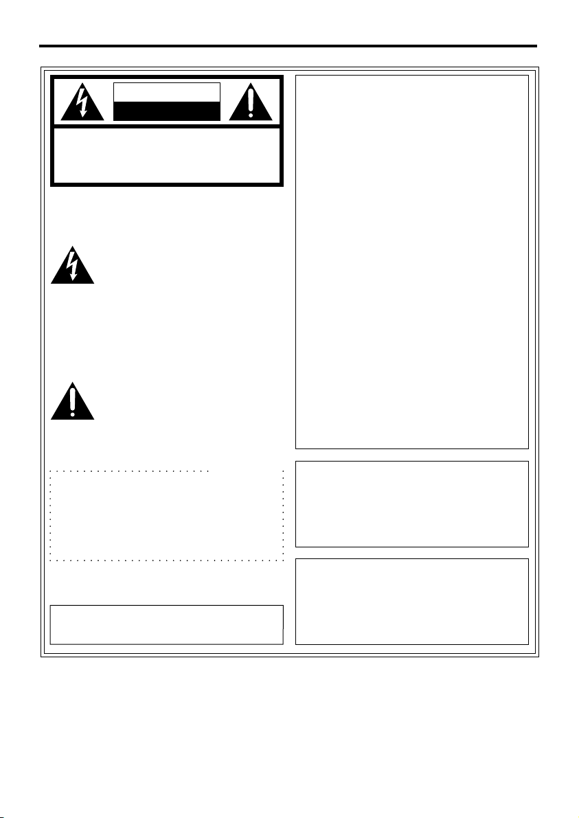
1 is the safety information.
CAUTION
CAUTION:
TO REDUCE THE RISK OF ELECTRIC SHOCK, DO NOT REMOVE
COVER (OR BACK).
NO USER SERVICEABLE PARTS INSIDE.
REFER TO SERVICING TO QUALIFIED SERVICE PERSONNEL.
RISK OF ELECTRIC SHOCK
DO NOT OPEN
The lightning flash with
arrowhead symbol, within an
equilateral triangle, is intended to
alert the user to the presence of
uninsulated “dangerous voltage”
within the product’s enclosure
that may be of sufficient
magnitude to constitute a risk of
electric shock to persons.
The exclamation point within an
equilateral triangle is intended to
alert the user to the presence of
important operating and maintenance (servicing) instructions
in the literature accompanying
the appliance.
CAUTION:
TO REDUCE THE RISK OF FIRE OR
SHOCK HAZARD AND ANNOYING
INTERFERENCE, USE THE RECOMMENDED ACCESSORIES ONLY.
WARNING:
TO REDUCE THE RISK OF FIRE OR
SHOCK HAZARD, DO NOT EXPOSE
THIS EQUIPMENT TO RAIN OR
MOISTURE.
This class A digital apparatus complies
with Canadian ICES-003.
Cet appareil numérique de la classe A
est conforme à la norme NMB-003 du
Canada.
For CANADA
12 Volt Class II Power Supply Only.
(For Example: AW-PS505P)
For Your Safety
Page 3

3
Contents
For Your Safety . . . . . . . . . . . . . . . . . . . . . . . . . . . . . . . . . . . . . . . . . . . . . . . . . . .2
Outline . . . . . . . . . . . . . . . . . . . . . . . . . . . . . . . . . . . . . . . . . . . . . . . . . . . . . . . . . .3
Precautions for Use . . . . . . . . . . . . . . . . . . . . . . . . . . . . . . . . . . . . . . . . . . . . . . .3
Controls and their Functions
_ Front panel . . . . . . . . . . . . . . . . . . . . . . . . . . . . . . . . . . . . . . . . . . . . . . . . . . . .4
_ Rear panel . . . . . . . . . . . . . . . . . . . . . . . . . . . . . . . . . . . . . . . . . . . . . . . . . . . .5
How To Connect . . . . . . . . . . . . . . . . . . . . . . . . . . . . . . . . . . . . . . . . . . . . . . . . . .7
Appearance and Dimensions . . . . . . . . . . . . . . . . . . . . . . . . . . . . . . . . . . . . . . . .8
Specifications . . . . . . . . . . . . . . . . . . . . . . . . . . . . . . . . . . . . . . . . . . . . . . . . . . . .9
Outline
≥ This unit is able to separate multiple data (camera control data and swivel stand control
data) transmitted from the camera controller (AK-HRP900P), and to output the control
information to the multi-purpose camera (AK-HC900P) and the swivel stand (AWPH300A, etc.).
≥ The distance between this unit and the camera is 33 ft (10m) max.
Precautions for Use
≥ We recommend that the AC adapter AW-PS505P is used for power supply.
≥ Handle the unit with care.
If dropped or given a strong shock, it may cause a trouble or accident.
≥ Use the unit in a temperature range of 32oF to 104oF (0oC to + 40oC).
If used at a temperature below 32oF or higher than 104oF, it may cause bad influences to
the component parts.
≥ Turn off the power before connecting or disconnecting the cable.
When connecting or disconnecting the cable, be sure to turn off the power switch of the
unit beforehand.
≥ Avoid using the unit outdoors.
≥ Install the unit 3.3 ft (1 m) away from the monitor.
≥ Maintenance
Pull out the power cord plug and clean the unit with dry cloth. If it is hard to clean,
moisten the cloth with a diluted neutral detergent solution and squeeze it well and lightly
wipe the unit.
≥ Do not use volatile solvents such as benzene or thinner.
≥ When using a chemical mop, carefully read the instructions.
Precautions
Page 4

4
_Front panel
POWER
OFF ON
Interface Adapter
1
2
1 Power indication LED [POWER]
When the power control switch 2 is ON, it is lighted green. With the power control
switch 2 set to OFF, it goes out.
2 Power control switch [POWER ON/OFF]
When this switch is set to ON, this unit and the camera connected to it are turned on.
With the switch set to OFF, both of the unit and the camera are tuned off.
Controls and their Functions
Page 5

3 Camera connector [CAMERA I/F]
Connected to the camera (AK-HC900P) with the attached multi-cable.
4 Swivel stand control signal output connector [PAN/TILT CONTROL OUT]
Connected to the swivel stand.
5 Control data input connector [DATA IN]
Used to input the data multiplexed by the camera controller (AK-HRP900P).
5
CAMERA
CN
DATA I N
BEAKER
DC 12V
IN
PAN/TILT
CONTROL OUT
34 5 7
6
_Rear panel
17
234
56
8
9101112131415
17
234
56
8
9101112131415
17
234
56
8
9101112131415
Controls and their Functions
Signal
NC
NC
NC
NC
DC 12V
Frame GND
TXD (H)
Pin No
8
9
10
11
12
13
14
15
Signal
NC
NC
NC
NC
DC GND
TXD (C)
RXD (H)
RXD (C)
Pin No
1
2
3
4
5
6
7
TXD: Data from camera to remote controller.
RXD: Data from remote controller to camera.
Pin No
1
2
3
4
5
6
7
Signal
NC
NC
NC
NC
NC
Frame GND
TXD (H)
Pin No
8
9
10
11
12
13
14
15
Signal
NC
NC
NC
NC
NC
TXD (C)
RXD (H)
RXD (C)
Page 6

Signal
GND
–––
12V
6
6 Breaker [BREAKER]
DC power breaker. The breaker operates to cut off the power in case of over-current.
7 DC12V input connector [DC 12V IN] (XLR4-pin)
Connects the AC adapter. We recommend that the AW-PS505P (option) is used.
1
2
3
4
Controls and their Functions
Pin No
1
2, 3
4
Page 7

How To Connect
7
O I
BREAKER
ZOOM/
FOCUS
SDI OUT
1
2
1
/
F
G/LI N Pb OUT Pr / SDI
OUT
Y/VIDEO
OUT
1394
CONTROL IN
IP/RP
DC12V
IN
CAMERA I/F
LENSE I/F
ND/EXT
SDI
IN
CSOP
O I
O I
POWER
ON OFF
SD CARD
OPERATE
ALARM
SCENE
MODE
PRE
CAM BAR TEST
USER1 USER2
Camera Controller
TALLY
MENU
ON
MENU
SPEED ZOOM
TELE
WIDE
FAR
NEAR
FOCUS
12345
PRESET
CC FLTER
3200
CROSS
63004300
ND FLTER
11/321/161/4
SHUTTER
OFF
SYNCRO
STEP
GAIN
0
S1 S2
S3
9dB 18dB
AUTO
WHITE BLACK
GAIN
BLACK
AUTO
M-PED
IRIS
CHECK
Interface adapter
AK-HTF900P
≥ Make the connections with all the units turned off.
≥ We recommend that the AW-PS505P (option) is used as AC adapter
≥ Use a swivel stand, AW-PH300A, AW-PH500, AW-PH600, and an adapter suited for the
swivel stand.
Remote
(zoom/focus
control) cable
Swivel stand controller
AW-RP301
Swivel stand
AW-PH300A
Multi-purpose digital camera
AK-HC900P
Multi-cable (17 ft)
AK-HDMLTCA05
Camera controller
AK-HRP900P
HD monitor
AC adapter
AW-PS505P
DDC
power
cable
Coaxial cable (5C-FB)HD-SDI
AC adapter
AW-PS301
AC adapter
AW-PS505P
Swivel stand control is
possible for AWPH500/PH600 as well.
AC adapter
AW-PS300
Multi-cable (17ft)
AK-HDMLTCA05
Trans-
mission
Remote
control
spec. lens
Page 8

Appearance and Dimensions
8
( ): mm
POWER
OFF ON
Interface Adapter
CAMERA
CN
DATA IN
BEAKER
DC 12V
IN
PAN/TILT
CONTROL OUT
8-3/16z (206.5)
9-7/8z (250)
2-1/8z
(42.4)
7/16z
(10.3)
Page 9

Specifications
9
Swivel control output:
Switch function:
Cable max. extension distance:
Operating temperature:
Dimensions:
Weight:
Finish:
Control signal (RJ-45 8P modular jack)
Power control
33 ft (10m)
32oF to 104oF (0oC to +40oC)
8-3/16(W)k2-1/8(H)k9-7/8(D) inch
(206.5k52.7k250 mm)
Approx. 4.18 lbs (1.9 kg)
AV ivory coating (Munsell 7.9Y 6.8/0.8 approx. color)
1is the safety information.
Power supply: DC +12V (XLR 4-pin connector)
Power consumption: 25 W (with camera connected)
Weight and dimensions shown are approximate.
Specifications are subject to change without notice.
Page 10

10
Memo
Page 11

11
Memo
Page 12

F0902H
@
3
Printed in Japan
VQT0A80
PANASONIC BROADCAST & TELEVISION SYSTEMS COMPANY
UNIT COMPANY OF MATSUSHITA ELECTRIC CORPORATION OF AMERICA
Executive Office:
One Panasonic Way 4E-7, Secaucus, NJ 07094 (201)348-7000
EASTERN ZONE
One Panasonic Way 4E-7, Secaucus, NJ 07094 (201)348-7621
Southeast Region:
1225 Northbrook Parkway, Ste 1-160, Suwanee, GA 30024 (770) 338-6835
Central Region:
1707 N Randall Road E1-C-1, Elgin, IL 60123 (847) 468-5200
WESTERN ZONE:
3330 Cahuenga Blvd W., Los Angeles, CA 90068 (323) 436-3500
Government Marketing Department:
52 West Gude Drive, Rockville, MD 20850 (301) 738-3840
Broadcast PARTS INFORMATION & ORDERING:
9:00 a.m. – 5:00 p.m. (EST) (800) 334-4881/24 Hr. Fax (800) 334-4880
Emergency after hour parts orders (800) 334-4881
TECHNICAL SUPPORT:
Emergency 24 Hour Service (800) 222-0741
Panasonic Canada Inc.
5770 Ambler Drive, Mississauga, Ontario L4W 2T3 (905) 624-5010
Panasonic de Mexico S.A. de C.V.
Av angel Urraza Num. 1209 Col. de Valle 03100 Mexico, D.F. (52) 1 951 2127
Panasonic Sales Company
Division of Matsushita Electric of Puerto Rico Inc.
San Gabriel Industrial Park, 65th Infantry Ave., Km. 9.5, Carolina, Puerto Rico 00630 (787) 750-4300
 Loading...