

Panasonic AK-HRP900 User Manual
Before attempting to connect, operate or adjust this product,
please read these instructions completely and save this manual for future use.
Model AK-HRP900P
Camera Controller
2
For Your Safety
FCC Note:
This device complies with Part 15 of the
FCC Rules. To assure continued
compliance follow the attached installation instructions and do not make any
unauthorized modifications.
This equipment has been tested and
found to comply with the limits for a Class
A digital device, pursuant to Part 15 of
the FCC Rules. These limits are designed to provide reasonable protection
against harmful interference when the
equipment is operated in a commercial
environment. This equipment generates,
uses, and can radiate radio frequency
energy and, if not installed and used in
accordance with the instruction manual,
may cause harmful interference to radio
communications. Operation of this equipment in a residential area is likely to
cause harmful interference in which case
the user will be required to correct the
interference at his own expense.
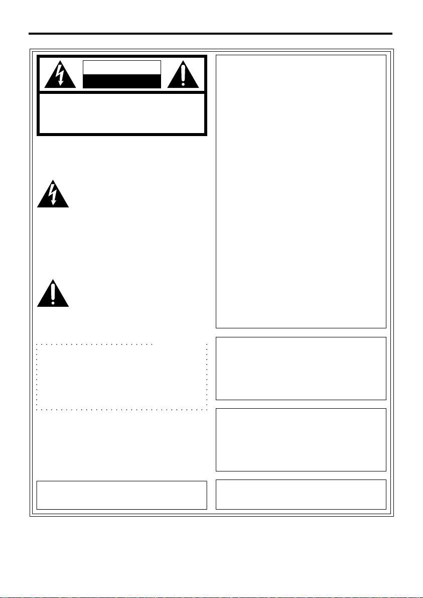
1 is the safety information.
CAUTION
CAUTION:
TO REDUCE THE RISK OF ELECTRIC SHOCK, DO NOT REMOVE
COVER (OR BACK).
NO USER SERVICEABLE PARTS INSIDE.
REFER TO SERVICING TO QUALIFIED SERVICE PERSONNEL.
RISK OF ELECTRIC SHOCK
DO NOT OPEN
The lightning flash with
arrowhead symbol, within an
equilateral triangle, is intended to
alert the user to the presence of
uninsulated “dangerous voltage”
within the product’s enclosure
that may be of sufficient
magnitude to constitute a risk of
electric shock to persons.
The exclamation point within an
equilateral triangle is intended to
alert the user to the presence of
important operating and maintenance (servicing) instructions
in the literature accompanying
the appliance.
CAUTION:
TO REDUCE THE RISK OF FIRE OR
SHOCK HAZARD AND ANNOYING
INTERFERENCE, USE THE RECOMMENDED ACCESSORIES ONLY.
WARNING:
TO REDUCE THE RISK OF FIRE OR
SHOCK HAZARD, DO NOT EXPOSE
THIS EQUIPMENT TO RAIN OR
MOISTURE.
The serial number of this product may
be found on the bottom of the unit.
This class A digital apparatus complies
with Canadian ICES-003.
Cet appareil numérique de la classe A
est conforme à la norme NMB-003 du
Canada.
For CANADA
12 Volt Class II Power Supply Only.
(For Example: AW-PS505P)
For Your Safety

3
Contents
For Your Safety . . . . . . . . . . . . . . . . . . . . . . . . . . . . . . . . . . . . . . . . . . . . . . . . . . .2
Outline . . . . . . . . . . . . . . . . . . . . . . . . . . . . . . . . . . . . . . . . . . . . . . . . . . . . . . . . . .4
Check the Accessories . . . . . . . . . . . . . . . . . . . . . . . . . . . . . . . . . . . . . . . . . . . . .4
Precautions for Use . . . . . . . . . . . . . . . . . . . . . . . . . . . . . . . . . . . . . . . . . . . . . . .4
Controls and their Functions . . . . . . . . . . . . . . . . . . . . . . . . . . . . . . . . . . . . . . . . .5
_ Operation panel . . . . . . . . . . . . . . . . . . . . . . . . . . . . . . . . . . . . . . . . . . . . . . . .5
_ Rear panel . . . . . . . . . . . . . . . . . . . . . . . . . . . . . . . . . . . . . . . . . . . . . . . . . . . .9
_ Front panel . . . . . . . . . . . . . . . . . . . . . . . . . . . . . . . . . . . . . . . . . . . . . . . . . . .11
How To Connect . . . . . . . . . . . . . . . . . . . . . . . . . . . . . . . . . . . . . . . . . . . . . . . . .12
_ Lens connection in the case of no swivel stand . . . . . . . . . . . . . . . . . . . . . . .13
Multi-purpose digital camera control system configuration 1 . . . . . . . . . . . . . . .14
Multi-purpose digital camera control system configuration 2 . . . . . . . . . . . . . . .15
Multi-purpose digital camera control system configuration 3 . . . . . . . . . . . . . . .16
Communication speed setting . . . . . . . . . . . . . . . . . . . . . . . . . . . . . . . . . . . . . . .17
Example of Rack Mount . . . . . . . . . . . . . . . . . . . . . . . . . . . . . . . . . . . . . . . . . . .18
_ How to rack-mount . . . . . . . . . . . . . . . . . . . . . . . . . . . . . . . . . . . . . . . . . . . . .18
_ How to change the rear panel position . . . . . . . . . . . . . . . . . . . . . . . . . . . . . .19
Appearance and Dimensions . . . . . . . . . . . . . . . . . . . . . . . . . . . . . . . . . . . . . . .20
Specifications . . . . . . . . . . . . . . . . . . . . . . . . . . . . . . . . . . . . . . . . . . . . . . . . . . .21

4
Outline
Coupling . . . . . . . . . . . . . . . . . . . . . . .1 pc
Multi-cable . . . . . . . . . . . . . . . . . . . . . .1 pc
Seal . . . . . . . . . . . . . . . . . . . . . . . . . . .1 pc
Setscrews . . . . . . . . . . . . . . . . . . . . .8 pcs
M4 x 8 mm . . . . . . . .4 pcs
M5 x 8 mm . . . . . . . .4 pcs
≥ This unit is a camera controller for multi-purpose camera (AK-HC900P). This
unit is connected to a multi-purpose camera with one multi-cable, and capable
of transmitting and receiving various camera and lens control signals, analog
picture signals of cameras, and generator lock signals (3-value SYNC).
≥ The extension distance between this unit and the camera is 33 ft (10m) max.
≥ It is possible to control the swivel stand from the pan-tilt control panel AW-
RP301 by using the swivel stand control input connector.
Check the Accessories
Precautions for Use
≥ We recommend that the AC adapter AW-PS505P is used for power supply.
≥ Handle the unit with care.
If dropped or given a strong shock, it may cause a trouble or accident.
≥ Use the unit in a temperature range of 32oF to 104oF (0oC to + 40oC).
If used at a temperature below 32oF or higher than 104oF, it may cause bad influences to
the component parts.
≥ Turn off the power before connecting or disconnecting the cable.
When connecting or disconnecting the cable, be sure to turn off the power switch of the
unit beforehand.
≥ Avoid using the unit outdoors.
≥ Install the unit 3.3 ft (1 m) away from the monitor.
≥ Maintenance
Pull out the power cord plug and clean the unit with dry cloth. If it is hard to clean,
moisten the cloth with a diluted neutral detergent solution and squeeze it well and lightly
wipe the unit.
≥ Do not use volatile solvents such as benzene or thinner.
≥ When using a chemical mop, carefully read the instructions.
Precautions

5
_Operation panel
POWER
ON OFF
SD CARD
OPERATE
ALARM
SCENE
MODE
PRE
CAM BAR TEST
USER1 USER2
Camera Controller
TALLY
MENU
ON
MENU
SPEED ZOOM
TELE
WIDE
FAR
NEAR
FOCUS
12345
PRESET
CC FLTER
3200
CROSS
63004300
ND FLTER
CLEAR 1/321/161/4
SHUTTER
OFF
SYNCRO
STEP
GAIN
0
S1 S2
S3
9dB 18dB
AUTO
WHITE BLACK
GAIN
BLACK
AUTO
M-PED
IRIS
CHECK
123<=>
?
@
A
B
C
D
E
F
G
: ;HIJ K L
4
5
6
7
8
9
1 Power indication LED [POWER]
It is lighted green when the power control switch 2 is ON. It goes out when the power
control switch 2 is OFF.
2 Power control switch [POWER ON/OFF]
With this switch turned ON, the unit and the camera connected are simultaneously
turned on. With it turned OFF, both of the unit and the camera are turned off.
3 SD card slot [SD CARD]
With an SD card inserted, the camera setting data can be recorded on the SD card.
4 Tally LED [TALLY]
It is lighted red when tally signal is input to the tally signal input terminal Q.
Controls and their Functions

6
5 Menu operation switch [MENU]
Operation switch for camera menu.
Item selection or data change can be done by turning this switch. When this switch
pushed, the item and data are settled.
6 Menu ON switch [MENU ON]
Used to turn the camera menu ON/OFF.
7 Preset memory switch [MEMO]
Preset memory can be done up to 5 points with respect to lens zoom, focus, and iris
position (when iris select switch K is at [MANU]). When using the preset memory, first
set the lens focus, zoom, and iris. Next, push this switch, then the switch is lighted.
Subsequently, push the desired preset position select switch 8. With the data stored in
the memory, the switch is lighted.
8 Preset position select switch [PRESET]
It calls the lens zoom, focus and iris settings previously stored in the memory, and
brings the lens into preset operation.
9 Speed change switch [SPEED]
High speed operation is obtained when the zoom operation lever : and the focus
adjust lever ; are operated while pressing this switch. The switch is lighted while being
pressed.
: Zoom operation lever [ZOOM TELE/WIDE]
Used for zoom operation of the lens. The zoom speed changes with the shifting angles
of the lever. With the zoom operation lever direction change switch T set at [NOR],
when the lever is shifted to [TELE], the zoom operates in a telescopic mode, and when
shifted to [WIDE], it operates in a wide angle mode. With the zoom operation lever
direction change switch T set to [REV], the zoom can be operated in the opposite
direction.
; Focus adjust lever [FOCUS FAR/NEAR]
Used to adjust the lens focus. The focus can be controlled in speed variable fashion by
regulating the shifting angle of this lever.
With the focus adjust direction change switch U set at [NOR], when this lever is shifted
to [FAR], the focus is adjusted to a far distance, and when shifted to [NEAR], the focus
is adjusted to a near distance. With the focus adjust direction change switch U set to
[REV], the focus can be adjusted in the opposite direction.
< Operation panel active switch [OPERATE]
This is an active switch for panel function. It can be operated when the switch is lighted.
It does not work when the switch is not lighted.
Controls and their Functions

7
Controls and their Functions
= Alarm indication LED [ALARM]
It lights up when an alarm is generated (in case of fan stop, wrong communication
speed, etc.).
Note:
In case of wrong communication speed, change the DIP SW position in the unit to
match the camera and communication speed so that the alarm goes out.
> Scene file select switch [SCENE]
Used to select the scene file previously set on the camera.
Note:
With [PRESET] selected, it results in the factory-adjusted setting.
? Mode select switch [MODE]
Used to select the camera color bar signal, test signal and camera picture signal. With
the switch set to [BAR], [TEST], the color bar signal and the test signal are output from
the monitor signal output terminal of this unit. With it set to [CAM], the picture taken by
the camera is output.
@ Auto white start switch [AUTO WHITE]
With this switch pressed, the white balance is automatically adjusted. During the
operation, WHTE LED blinks, and it goes out when the adjustment is normally finished.
In case of NG, it lights up for a while and then goes out.
Note:
It does not operate when the mode is [BAR].
A Auto black start switch [AUTO BLACK]
With this switch pressed, the lens is automatically closed, and the black balance is
adjusted. During the operation, BLACK LED blinks, and it goes out when the
adjustment is normally finished. In case of NG, it lights up for a while and then goes
out.
B R/B gain adjust volume [GAIN]
Used to adjust the R/B signal gain of the camera.
C R/B pedestal adjust volume [BLACK]
Used to adjust the R/B signal pedestal level of the camera.
D ND filter select switch [ND FILTER]
Used to select the optical filter (ND) of the camera.
E CC filter select switch [CC FILTER]
Used to select the optical filter (CC) of the camera.

8
F Gain select switch [GAIN]
Used to select the master gain of the camera. It changes in the order of 0dB )9dB
)18dB )S1 (Super gain 1) )S2 )3dB )0dB.
Note:
For super gain setting, check with the camera menu.
G Shutter select switch [SHUTTER OFF/STEP/SYNCHRO]
Used to select the electronic shutter of STEP and SYNCHRO set on the camera.
Note:
For electronic shutter setting, check with the camera menu.
H Indication change switch [CHECK]
Used to change the indication item.
I Indicator
It indicates the F value of iris.
J Master pedestal adjust volume [M-PED]
Used to adjust the pedestal setting of Y (luminance) signal of the camera.
K Lens iris auto/manual select switch [IRIS AUTO]
Used to select the lens iris adjusting method.
With the switch set to [AUTO], the lens is shifted to auto iris mode, and the iris is
automatically adjusted according to the amount of light coming into the lens.
With the switch set to [MANU], the lens iris can be moved in the range from close to
open by turning the lens iris adjust VR (volume) L.
When storing the lens iris in the preset position select switch 8 by using the preset
memory switch 7, set to [MANU] mode. It does not work in [AUTO] mode.
L Iris adjust volume [IRIS]
When the lens iris auto/manual select switch K is set at [MANU], the lens iris can be
moved in the range from close to open.
When the lens iris auto/manual select switch K is set at [MANU], press the preset
position select switch 8 to call the preset memory, then the lens iris position is set to
the preset memory position irrespective of the VR (volume) position. After that, when
the VR is turned, the lens iris returns to the value of VR.
Controls and their Functions
 Loading...