

Page 1
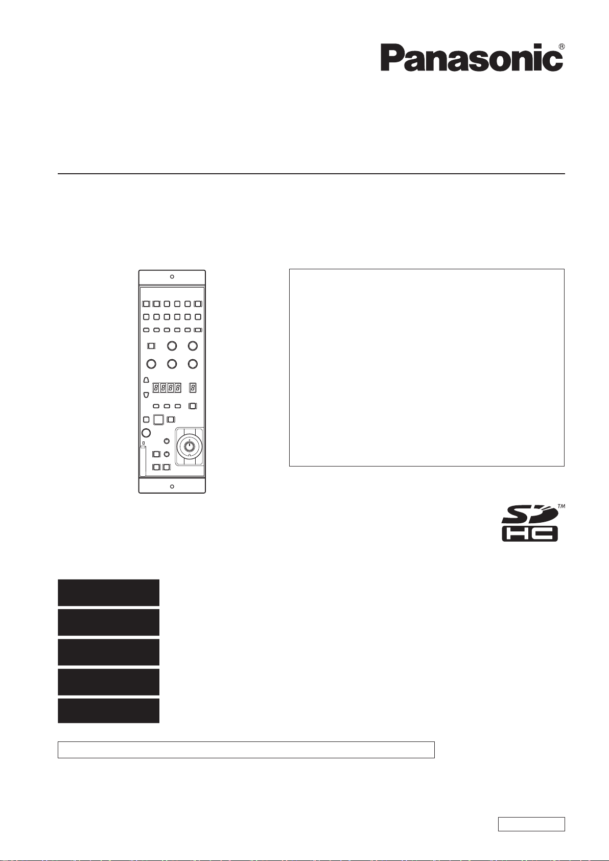
Operating Instructions
<Basics>
Remote Operation Panel
Model No.
AK-HRP200G
●● How●the●operating●instructions●are●organized
・●Basics●(this●manual):
This manual describes how to connect the unit to
the required equipment and set it up.
Before installing the unit, be sure to read the
<Basics> manual to ensure that you know how to
install it correctly.
The <Basics> manual is provided as a PDF file on the
CD-ROM supplied with the unit.
・●Operations●and●Settings:
Operations and Settings describe how to operate
and set up the unit.
The <Operations and Settings> manual is provided
as a PDF file on the CD-ROM supplied with the unit.
●● To●read●PDF●files,●you●will●need●Adobe
You●can●download●it●from●Adobe●Systems'●website.
®
●Reader®.●
DEUTSCH
FRANÇAIS
ITALIANO
ESPAÑOL
日本語
This manual is also contained as a PDF file on the CD-ROM supplied with the unit. (→page 4)
Before operating this product, please read the instructions carefully and save this manual for future use.
SS1012KT0 -PS
Printed in Japan
Für Erlauterungen in Deutsch, konsultieren Sie bitte die mitgelieferte CD-ROM.
(→ Seite 4)
Pour des explications en français, veuillez vous reporter au CD-ROM fourni.
(→ page 4)
Per le istruzioni in italiano, vedere il CD-ROM in dotazione. (→ pagina 4)
Para la explicación en español, consulte el CD-ROM suministrado. (→ página 4)
日本語版の取扱説明書は付属のCD-ROMに納められています。(→4ページ)
ENGLISH
VQT4S52
Page 2
3
Read this first!
DO NOT REMOVE PANEL COVERS BY UNSCREWING
THEM.
No user serviceable parts inside.
Refer servicing to qualified service personnel.
WARNING:
• To reduce the risk of fire, do not expose this equipment to rain
or moisture.
• To reduce the risk of fire, keep this equipment away from all
liquids. Use and store only in locations which are not exposed
to the risk of dripping or splashing liquids, and do not place any
liquid containers on top of the equipment.
CAUTION:
Do not remove panel covers by unscrewing.
To reduce the risk of electric shock, do not remove the covers. No
user serviceable parts inside.
Refer servicing to qualified service personnel.
CAUTION:
To reduce the risk of fire or electric shock and annoying
interference, use the recommended accessories only.
WARNING:
Always keep memory cards (optional accessory) out of the reach
of babies and small children.
indicates safety information.
FCC NOTICE(USA)
This device complies with part 15 of the FCC Rules. Operation is subject to the following two conditions:
(1) This device may not cause harmful interference, and (2) this device must accept any interference received, including interference that may
cause undesired operation
CAUTION:
This equipment has been tested and found to comply with the limits for a class A digital device, pursuant to Part 15 of the FCC Rules.
These limits are designed to provide reasonable protection against harmful interference when the equipment is operated in a commercial
environment. This equipment generates, uses, and can radiate radio frequency energy and, if not installed and used in accordance with the
instruction manual, may cause harmful interference to radio communications.
Operation of this equipment in a residential area is likely to cause harmful interference in which case the user will be required to correct the
interference at his own expense.
FCC Warning:
To assure continued FCC emission limit compliance, follow the attached installation instructions and the user must use only shielded interface
cables when connecting to host computer or peripheral devices.
Also, any unauthorized changes or modifications to this equipment could void the user’s authority to operate this device.
NOTIFICATION(Canada)
This class A digital apparatus complies with Canadian ICES-003.
indicates safety information.
EEE Yönetmeliğine Uygundur.
EEE Complies with Directive of Turkey.
Note:
The rating plate (serial number plate) is on the bottom of the unit.
Importer’s name and address of pursuant to EU rules:
Panasonic Testing Centre
Panasonic Marketing Europe GmbH
Winsbergring 15, 22525 Hamburg, Germany
2
Page 3

Read this first! (continued)
EMC NOTICE FOR THE PURCHASER/USER OF THE APPARATUS
1. Applicable standards and operating environment (AK-HRP200)
The apparatus is compliant with:
• standards EN55103-1 and EN55103-2 2009, and
• electromagnetic environments E1, E2, E3, E4 and E5.
2. Pre-requisite conditions to achieving compliance with the above standards
<1> Peripheral equipment to be connected to the apparatus and special connecting cables
• The purchaser/user is urged to use only equipment which has been recommended by us as peripheral equipment to be connected to the
apparatus.
• The purchaser/user is urged to use only the connecting cables described below.
<2> For the connecting cables, use shielded cables which suit the intended purpose of the apparatus.
• Video signal connecting cables
Use double shielded coaxial cables, which are designed for 75-ohm type high-frequency applications, for SDI (Serial Digital Interface).
Coaxial cables, which are designed for 75-ohm type high-frequency applications, are recommended for analog video signals.
• Audio signal connecting cables
If your apparatus supports AES/EBU serial digital audio signals, use cables designed for AES/EBU.
Use shielded cables, which provide quality performance for high-frequency transmission applications, for analog audio signals.
• Other connecting cables (LAN, RS-422)
Use shielded cables, which provide quality performance for high-frequency applications, as connecting cables.
• When connecting to the DVI signal terminal, use a cable with a ferrite core.
• If your apparatus is supplied with ferrite core(s), they must be attached on cable(s) following instructions in this manual.
3. Performance level
The performance level of the apparatus is equivalent to or better than the performance level required by these standards.
However, the apparatus may be adversely affected by interference if it is being used in an EMC environment, such as an area where strong
electromagnetic fields are generated (by the presence of signal transmission towers, cellular phones, etc.). In order to minimize the adverse
effects of the interference on the apparatus in cases like this, it is recommended that the following steps be taken with the apparatus being
affected and with its operating environment:
1. Place the apparatus at a distance from the source of the interference.
2. Change the direction of the apparatus.
3. Change the connection method used for the apparatus.
4. Connect the apparatus to another power outlet where the power is not shared by any other appliances.
Вимогам Технічного Регламенту Обмеження Використання деяких Небезпечних Речовин в електричному та електронному обладнанні
(затвердженого Постановою №1057 Кабінету Міністрів України)
Виріб відповідає вимогам Технічного Регламенту Обмеження Використання деяких Небезпечних Речовин в електричному та електронному
обладнанні (ТР ОВНР).
Вміст небезпечних речовин у випадках, не обумовлених в Додатку №2 ТР ОВНР, :
1. свинець(Pb) – не перевищує 0,1 % ваги речовини або в концентрації до 1000 частин на мільйон;
2. кадмій (Cd)– не перевищує 0,01 % ваги речовини або в концентрації до 100 частин на мільйон;
3. ртуть(Hg) – не перевищує 0,1 % ваги речовини або в концентрації до 1000 частин на мільйон;
4. шестивалентний хром (Cr6+ ) – не перевищує 0,1 % ваги речовини або в концентрації до 1000 частин на мільйон;
5. полібромбіфеноли (PBB) – не перевищує 0,1% ваги речовини або в концентрації до 1000 частин на мільйон;
6. полібромдефенілові ефіри (PBDE) – не перевищує 0,1 % ваги речовини або в концентрації до 1000 частин на мільйон.
Декларація про Відповідність
IMPORTANT SAFETY INSTRUCTIONS
1) Read these instructions.
2) Keep these instructions.
3) Heed all warnings.
4) Follow all instructions.
5) Do not use this apparatus near water.
6) Clean only with dry cloth.
7) Do not block any ventilation openings. Install in accordance with the manufacturer’s instructions.
8) Do not install near any heat sources such as radiators, heat registers, stoves, or other apparatus (including amplifiers) that produce heat.
9) Do not defeat the safety purpose of the polarized or grounding-type plug. A polarized plug has two blades with one wider than the other. A
grounding-type plug has two blades and a third grounding prong. The wide blade or the third prong are provided for your safety. If the provided plug
does not fit into your outlet, consult an electrician for replacement of the obsolete outlet.
10) Protect the power cable from being walked on or pinched particularly at plugs, convenience receptacles, and the point where they exit from the
apparatus.
11) Only use attachments/accessories specified by the manufacturer.
12) Use only with the cart, stand, tripod, bracket, or table specified by the manufacturer, or sold with the apparatus. When a cart is used,
use caution when moving the cart/apparatus combination to avoid injury from tip-over.
13) Unplug this apparatus during lightning storms or when unused for long periods of time.
14) Refer all servicing to qualified service personnel. Servicing is required when the apparatus has been damaged in any way, such as
power-supply cord or plug is damaged, liquid has been spilled or objects have fallen into the apparatus, the apparatus has been
exposed to rain or moisture, does not operate normally, or has been dropped.
Page 4

Read this first! (continued)
ENGLISH
How to open the operating instruction manual PDF files
Discontinue installation if the installation screen of the software opens as
a result of inserting the CD-ROM.
When [INDEX.pdf] on the CD-ROM is opened, a list of the operating
instruction manuals will be displayed.
Click on the document name of the manual to be opened.
Adobe® Reader® is required to read PDF files.
It can be downloaded from the home page of Adobe
Systems.
DEUTSCH
Öffnen der PDF-Dateien der Bedienungsanleitung
Brechen Sie die Installation ab, falls beim Einlegen der CD-ROM der
Installationsbildschirm der Software erscheint.
Wenn [INDEX.pdf] auf der CD-ROM geöffnet wird, erscheint eine Liste
der Bedienungsanleitungen.
Klicken Sie auf den Dokumentennamen der zu öffnenden
Anleitung.
Zum Lesen der PDF-Dateien benötigen Sie Adobe®
®
Reader
Dieses Programm kann von der Homepage von Adobe
Systems heruntergeladen werden.
.
ITALIANO
Come aprire i file dei manuali di istruzioni per l’uso
Se inserendo il CD-ROM si apre la schermata di installazione del
software, interrompere l’installazione.
Aprendo [INDEX.pdf] sul CD-ROM, viene visualizzato un elenco di
manuali di istruzioni per l’uso.
Fare clic sul nome del documento corrispondente al manuale da aprire.
Per leggere i file PDF è necessario Adobe® Reader®.
Il programma può essere scaricato dal sito Web di Adobe
Systems.
ESPAÑOL
Modo de abrir los archivos PDF que contienen el manual
de las instrucciones de funcionamiento
Interrumpa la instalacion si la pantalla de instalacion del software se
abre como resultado de insertar el CD-ROM.
Cuando se abra [INDEX.pdf] en el CD-ROM se visualizara una lista de
los manuales de instrucciones de funcionamiento.
Haga clic en el nombre de documento del manual que va a abrir.
Para leer los archivos PDF se necesita el programa
®
Adobe
Este programa se puede descargar de la pagina inicial de
Adobe Systems.
Reader®.
FRANÇAIS
Comment ouvrir les fichiers PDF des manuels du mode
d’emploi
Arrêter l’installation si l’écran d’installation du logiciel s’ouvre quand le
CD-ROM est inséré.
Quand [INDEX.pdf] sur le CD-ROM s’ouvre, la liste des manuels du
mode d’emploi s’affiche.
Cliquer sur le nom du document correspondant au manuel à
consulter.
Adobe® Reader® est nécessaire pour lire les fichiers PDF.
Ce logiciel peut être téléchargé depuis la page d’accueil
d’Adobe Systems.
日本語
取扱説明書PDFファイルの聞き方
CD-ROMを挿入してソフトウエアのインストール画面が立ち上がる場
合は、インストールを中止してください。
CD-ROM内の[INDEX.pdf]を聞くと取扱説明書の一覧が表示されま
す。
開きたい取扱説明書のドキュメント名をクリックしてください。
PDFファイルをご覧いただくには、Adobe®Reader®が
必要です。
アドビシステムズ社のホームページからダウンロードしてく
ださい。
4
Page 5

About this instruction manual
About trademarks and registered trademarks
• Adobe® and Reader® are either registered trademarks or trademarks of Adobe Systems Incorporated in the United States and other countries.
• SDHC logo is a trademark of SD-3C and LLC.
• Other names of companies or products in this manual are either registered trademarks or trademarks of their respective owners.
About copyright
Distributing, copying, disassembling, reverse compiling, reverse engineering and also exporting in violation of export laws of the software provided
with this unit are expressly prohibited.
Abbreviations
The following abbreviations are used in this manual.
• The AK-HRP200G is referred to as the AK-HRP200 in this manual.
• The term memory card will be used below as a generic term for both SD and SDHC memory cards.
SD or SDHC will be used in descriptions that refer to only one of the two card types.
• A studio handy camera is referred to as a camera in this manual.
• A camera control unit is referred to as a CCU in this manual.
• A remote operation panel is referred to as an ROP in this manual.
Illustrations and screen displays in this manual
• Illustrations and screen displays in the manual may differ from those actually displayed.
Table of Contents
Read this first! .......................................................................................2
About this instruction manual .............................................................. 5
Introduction ............................................................................................ 6
Features.................................................................................................. 7
Accessories ...........................................................................................7
Precautions for use ............................................................................... 7
Precautions for installation .................................................................. 8
Setting up the unit ................................................................................. 8
Installing and removing rack mount brackets....................................... 8
Rack installation (rack mounting) ......................................................... 8
System component connections .......................................................... 9
Outside dimension drawing .................................................................9
Parts and their functions .................................................................... 10
Operation panel .................................................................................10
Connector Panel ................................................................................ 18
Dip Switches ...................................................................................... 18
Specifications ...................................................................................... 19
Index ..................................................................................................... 19
5
Page 6

7
Introduction
Overview
This unit is a remote operation panel for controlling a studio handy
camera (AK-HC3800) and a camera controller unit (AK-HCU200).
Use a dedicated optical fiber cable to connect a studio handy camera
to a camera controller unit and use an ROP cable to connect this unit
to the camera controller unit.
Memory Cards
Use only memory cards that comply with the SD and SDHC
specifications in this unit.
Be sure to format memory cards in this unit.
This unit supports the following memory card capacities.
It does not support SDXC memory cards.
SD memory cards: 8 MB to 2 GB
SDHC memory cards: 4 GB to 32 GB
For the latest information not available in the Operating Instructions,
visit the following Web site.
http://pro-av.panasonic.net/
Pay attention to the following when using and storing the unit.
• Avoid locations exposed to high temperature and humidity
• Avoid exposure to condensation
• Avoid static electricity.
Software upgrades
For upgrades, visit Support & Download on the Panasonic website.
http://pro-av.panasonic.net/
Follow the instructions included in the download file to perform the
upgrade.
Disclaimer
Panasonic Corporation will not accept any liability whatsoever for any
of the following.
(1) Any direct, indirect, accidental, special or consequential damage
or loss related to this unit
(2) Personal injury or equipment damage caused by inappropriate use
or negligent operation of the user
(3) Disassembly, repair or modification of the unit by the user
(4) Inconvenience, loss or damage when images cannot be displayed
for whatever reason including unit failure or defects
(5) Any defect or inconvenience, loss or damage resulting from such
a defect arising when the unit is combined with the device of a
third party
(6) Loss of recorded data for whatever reason
6
Page 7

Features
z This unit is a remote operation panel for controlling a studio
handy camera (AK-HC3800) and a camera controller unit like the
AK-HCU200.
z A simple button layout and an IRIS control lever ensure intuitive and
stable operation.
z Scene files, user files and lens files can be stored on memory cards.
Accessories
Make sure that the following accessories are supplied.
• Be sure to appropriately dispose of the packing material when you have unpacked the product.
CD-ROM .................................................................................................... 1
• Operating Instructions <Basics>
• Operating Instructions <Operations and Settings>
Precautions for use
Observe the following in addition to the information included in “Read this first!”.
Handle carefully
Do not drop the unit or expose it to strong impacts or vibrations. Do
not carry the unit by the iris lever. The unit could be damaged or
cause an accident.
Use the unit within a temperature range of 0°C to 40°C
(32°F to 104°F).
Exposure to temperatures below 0°C (32°F) or above 40°C (104°F)
could adversely affect Internal components.
Power off before connecting or disconnecting cables
Connect and disconnect cables when the unit is turned off (when the
CCU is off, the ROP cable is disconnected and an external DC power
supply is not connected).
Avoid humidity and dust
Avoid using the unit in an excessively humid or dusty location to
prevent damage to internal components.
Maintenance
Turn the unit off and wipe it with a dry cloth. To remove stubborn
soiling, immerse a cloth in a solution of a neutral kitchen detergent
and water, wring it out thoroughly and wipe the unit gently. Then wipe
it with a dry cloth to remove any moisture.
<Note>
• Do not use benzine, paint thinner or other volatile fluids.
• If you use a chemical cloth for cleaning, read through the
precautions before use.
Avoid exposure to water
Make sure that the unit is not directly exposed to water. Exposure to
water could damage it.
Disposal
When the unit reaches the end of its service life, ask a special
contractor to dispose of it properly according to environmental
regulations.
7
Page 8

9
Precautions for installation
Observe the following in addition to the information included in “Read this first!”.
Have your supplier install the unit and handle connections.
Cable connections
• Be sure to use dedicated remote operation panel (ROP) cables.
• If the unit will not be used for an extended period of time, disconnect
the ROP cables to save electricity.
Handle carefully
• Make sure you do not drop or expose the unit to strong impacts or
vibrations that could damage the product or cause accidents.
Do not insert foreign material in the unit.
• Foreign materials such as water, metal objects, food or drink that
enter the unit could cause a fire or electrical shock.
Setting up the unit
Installing and removing rack mount brackets
Rack mount bracket
Securing screws
Installation location
• This unit is designed for indoor use.
• Use the unit on a stable and horizontal surface that is sufficiently
capable of supporting its weight.
• When the unit will be recessed into a panel or table, make sure that
enough space is provided for ventilation and cables.
• Do not install the unit in a location where it and the cables can be
easily damaged.
• Do not install the unit in a location where the temperature drops to
0°C (32°F) or lower or reaches 40°C (104°F) or higher.
• Do not install the unit in a location exposed to direct sunlight or near
exhaust vents that expel hot air.
• Do not install the unit in a location exposed to excessive humidity,
dust or vibrations to prevent malfunction.
The unit is shipped from the factory with the rack mount brackets
installed.
The customer can remove the four screws that hold the rack mount
brackets in place using a Phillips screwdriver.
<Note>
• After detaching, store the rack mount brackets and the screws in a
location easily accessible when required.
• Next time you use the rack mount brackets to secure the unit, tighten
the four screws to a torque of 50 N•cm or more.
Rack mount bracket
Securing screws
Rack installation (rack mounting)
Securing screw (commercially available)
Secure the unit to the rack using two screws.
<Note>
• The securing screws are not supplied with the unit. Purchase screws
that will fit the 5 mm (3/16 inch) in diameter holes before rack
mounting.
• The temperature in the rack must be between 0 °C (32°F) and 40 °C
(104°F).
8
Page 9

Setting up the unit (continued)
System component connections
1. Connect the CCU connector on this unit to the ROP
connector on the CCU rear panel using a dedicated ROP
cable (sold separately).
Connection example:
AK-HCU200
ROP cable
12V IN
LAN RS-422 PREVIEW
CCU
SIGNAL GND
AK-HRP200
Outside dimension drawing
Unit: mm (inch)
2-Φ5
46(1-13/16)
VF
HEAD
BARS
WHITE
POWER
POWER
TEST
KNEE
OFF
SKINDTLMATRIX5600K
SCENE/USER FILE
SCENE 2
SCENE 1
SHIFT
VR LOCK
SCENE 3
USER 2USER 1
USER 3
GAIN
AUTO
BLACK
SCENE 4
2. After having connected all the components, turn the CCU
main power on, and then turn the camera on.
<Note>
• If no camera is connected, the number of CCU functions that this unit
can control is limited.
• Turn off the CCU before disconnecting the ROP cable.
55(2-3/16)
53(2-1/16)
9(3/8)
20.3(13/16)
SET UP
DTL
SHUTTER
OFF
ON
STEP/SYNC
STORE
22(7/8)
70(2-3/4)
UP
DATA
SET
DOWN
SET UP
SHIFT
+
UP+DOWN
CHARA
MENU
SELECT
DTL
ND
M.GAIN
DISPLAY SELECT
ND/CC M.GAIN/M.PED
SAVE/LOAD
TALLY/CALL
ALM OPT
EXT
D.EXT
CLOSE
FLARE/PED
CC SHT SYNC
M.PED 10-19
IRIS
SHUTTER
EXECUTEEXIT
IRIS/M.PED LOCK IRIS
SENSE
COARSEAUTO
OPENCLOSE
FULL
46(1-13/16)
92(3-5/8)
CAMERA
No.
SELECT
M.PED
PUSH
PREVIEW
308(12-1/8)
290(11-7/16)
264(10-3/8)
120(4-3/4)
Page 10

11
Parts and their functions
Operation panel
A beep (buzzer) sounds when a button is pressed. However, buttons do not beep when the buzzer is set to Off in setup mode.
1 2 3 4 5 6
HEAD
POWER
7 8 9 10 11 12
1. Camera power button <HEAD POWER>
Use this button to control camera power remotely. However, it will not
function unless the CCU and the camera are turned on.
Each press of the button turns the power on and off.
On (green): The camera is turned on.
On (red): The camera is turned off.
Flashing
(red):
The unit is off.
When the camera is powered from an external DC power supply, the
button lights green and the camera power supply cannot be remotely
controlled from this unit.
2. Viewfinder power button <VF POWER>
Use this button to control camera viewfinder power remotely. It lights
when the unit is ON.
When the camera is turned on by the unit, the viewfinder is also
turned on.
Each press of the button turns the power On (power on) and Off
(power off).
On (green): Both the camera and viewfinder are On.
Off: The viewfinder has been turned off from the unit
<Note>
The button lights (green) or goes off with each press of the button
also when the viewfinder is turned off.
3. Color Bar Signal Output button <BARS/TEST>
Use this button to output the camera color bar signal from the camera
via the camera video output on the CCU rear panel.
To select a CCU color bar type, choose [SYSTEM(1/2)] [HD
COLOR BAR] in the ROP menu. (For details, refer to Operations and
Settings on the supplied CD-ROM)
Select the camera color bar from the camera menu. (Refer to the
operating instructions supplied with the camera.)
When the video signal is a camera signal or a color bar signal, press
and hold the Color Bar Signal Output <BARS/TEST> button to select
the TEST signal. To switch from TEST signal output, press the Color
Bar Signal Output button <BARS/TEST> to select camera video
output.
On (yellow): CCU color bar and camera color bar On
On (green): TEST signal On
Off: Camera video
VF
POWER
AUTO
BLACK
BARS
WHITE
TEST
KNEE
OFF
SKINDTLMATRIX5600K
SET UP
DTL
SHUTTER
OFF
ON
STEP/SYNC
4. Auto White Balance button <WHITE>
Use this button to automatically adjust the white balance.
On:
This indicates that the auto white balance adjustment has
started.
This warns that the automatic white balance adjustment
ended without being completed. When highlights and
Flashing:
lowlights are lost, white balance is returned to its previous
value. When correct white balance cannot be obtained,
adjustment stops at the last obtained value.
Off:
This indicates that the white balance has been adjusted
correctly.
Pressing the Auto White Balance button <WHITE> during white
balance adjustment (lamp on) cancels adjustment and turns the lamp
off. Then the white balance value returns to the value it had prior to
auto white balance adjustment.
<Note>
If the auto white balance adjustment is not completed, check the
message on the picture monitor (PM) on the CCU.
5. Auto Black Balance button <BLACK>
Use this button to automatically adjust the black balance.
Automatic white spot correction is performed simultaneously.
On:
This indicates that the automatic black balance adjustment
has started.
This warns that the automatic black balance adjustment
Flashing:
ended without being completed.
Auto black balance returns to the value it had prior to
adjustment.
Off:
This indicates that the black balance has been adjusted
correctly.
Pressing the Auto Black Balance button <BLACK> during black
balance adjustment (lamp on) cancels adjustment and turns the lamp
off. Then the black balance value returns to the value it had prior to
auto black balance adjustment.
<Note>
If the auto black balance adjustment is not completed, check the
message on the picture monitor (PM) on the CCU.
10
Page 11

Parts and their functions (continued)
6. Auto Setup button <SETUP>
Use this button to start auto setup.
The setup status is output to the picture monitor.
Choose [FUNCTION] [ASU SETUP] in the ROP menu to select
[OUT FULL] or [OUT EASY] mode. (For details, refer to Operations
and Settings on the supplied CD-ROM)
OUT FULL:
OUT EASY:
Align the position of the gray scale wedge with the angle of view in
the vertical direction of the viewfinder. Be sure to correctly select the
position from which you shoot the chart since some positions may not
enable a satisfactory auto setup.
(Recommended gray scale)
Standard setup based on an outdoor shooting chart
<Sequence of operation execution>
AWB→ABB→BSHD→ABB→AWB→FLARE→AWB
Easy setup based on an outdoor shooting chart
<Sequence of operation execution>
AWB→ABB→AWB→FLARE→AWB
10. Knee OFF button <KNEE OFF>
Use this button to cancel the knee function that attenuates those
areas of the video signals where a particular level (knee point) has
been exceeded so that they will not become saturated as easily.
On: Knee function is canceled. (Knee OFF)
Off: Knee function is on.
11. Detail OFF button <DTL OFF>
Use this button to cancel contour enhancement (hard/soft) (detail
enhancer) of image output.
On: Turns off contour enhancement (detail enhancer off)
Off: Turns on contour enhancement (detail enhancer on)
12. Shutter On/Off button <SHUTTER ON>
STEP/SYNC select button<STEP/SYNC>
Use thus button to turn the SHUTTER on or off. Press and hold the
button to switch between STEP and SYNCRO. In SHUTTER ON
mode, the SHUTTER display select button <SHUTTER> and the
SHUTTER display <SHT> goes on, and the setting appears on the
setting display for about 2 seconds.
On: SHUTTER ON (STEP/SYNCRO setting is available)
Off: SHUTTER OFF (STEP/SYNCRO setting is available)
z Starting auto setup
1. Press <SETUP>.
<SETUP> flashes at about 2-second intervals while the auto
setup start preparation mode is established, and a square
marker appears in the center of the camera viewfinder. Align
the white at the center of the gray scale with this square marker.
(To cancel setup button, press and hold the switch.)
2. Press <SETUP> again.
<SETUP> lights as auto setup starts. (Pressing <SETUP>
during the auto setup operation will abort auto setup.)
<SETUP> goes off when auto setup ends successfully.
If <SETUP> flashes at approximately 1-second intervals, auto
setup has ended without being completed. During the auto
setup operation, the picture monitor (PM) displays characters to
indicate operation status.
<Note>
If auto setup is not completed, check the message on the picture
monitor (PM) on the CCU.
7. 5600 K button <5600K>
Use this function to change the amplification rate of the RB signals
by an electrical circuit to achieve a white balance that corresponds
to a 5600K color temperature. When the 5600K button <5600K> is
set to On, the B video signal is attenuated by about −6 dB, the R
video signal is boosted by about 3 dB while the G video signal is not
attenuated.
Select this setting for shooting under a 5600K light source or when
shooting outdoors.
On: ON
Off: OFF
8. Matrix button <MATRIX>
Use this function to correct saturation and color phase according to
the gain setting of each color component in matrix memory. Each
press of the button turns the function on or off.
On: ON
Off: OFF
9. Skin Detail button <SKINDTL>
Use this button to apply coring to the detail enhancement of the skin
tone areas in the HDTV video output signals to soften or increase the
enhancement of skin tone details. Each press of the button turns the
function on or off.
On: ON
Off: OFF
Page 12

Parts and their functions (continued)
13
13 14 15
SHIFT
SCENE 1
SCENE/USER FILE
SCENE 2
USER 2USER 1
SCENE 3
USER 3
SCENE 4
STORE
13. Scene/User File selector button <SHIFT>
Use this button to determine whether the SCENE/USER FILE
select button will be used for selecting scene files or user files.
Simultaneously pressing this button and a SCENE/USER FILE select
button 1 to 3 <SCENE1/USER1> to <SCENE3/USER3> allows you to
select user files 1 to 3.
Scene file Scene files are mainly used by video
User file A user file is system setting data (reference
engineers (VE) to create the required image
characteristics.
file) composed of scene files and operation
data. The user can record user files.
For details on scene files and user files, refer to Operations and
Settings on the supplied CD-ROM and also Operating Instructions of
studio handy camera (AK-HC3800).
14. SCENE/USER FILE select buttons
<SCENE 1/USER1> to <SCENE 3/USER 3> <SCENE 4>
Use these buttons to open previously saved scene files (1 to 4) or
user files (1 to 3) when needed. You can also use them to store your
own scene files (1 to 4) or user files (1 to 3).
On: A scene file is selected
Off: A scene file is not selected
The button lights
for about 1 second
before going off:
z Opening a scene file
Press the SCENE/USER FILE select button <SCENE1/USER1>
to <SCENE3/USER3> or <SCENE4> for the number of the
scene file (1 to 4) you want to open.
The pressed button lights and the scene file opens.
The button remains lit even after the file has opened.
To cancel opening a scene file, press the SCENE/USER FILE
select button that is on to turn it off.
The setting information that was temporarily saved before the
scene file was opened is now restored, and the settings made
prior to the scene file call are also restored.
Pressing a SCENE/USER FILE select button other than the lit
scene/user file select button lights the button of that scene/user
file and opens it.
<Note>
Settings that are adjusted while the scene file is being opened or
after it has opened will persist when the power is turned off.
A user file is selected
15. Scene/user file store button <STORE>
Use this button to store your own scene files (1 to 4) or user files (1
to 3).
On: Indicates that a scene or user file can be stored
Off:
z Storing scene files to buttons 1 to 4
1. Press <STORE>.
2. Press the SCENE/USER FILE select button <SCENE1/
<Note>
Adjustments made after opening a scene file that is later stored
will be stored with the adjustments. The stored scene file is then
selected and the corresponding SCENE/USER FILE select button
lights.
z Storing settings to user files 1 to 3
1. Adjust and set up the camera to the status you want to
2. Press <STORE>.
3. In this condition, hold down <SHIFT> and press the SCENE/
<Note>
A scene file that is open or about to open will remain selected
when stored in a user file.
Indicates that the scene or user file has been stored or
canceled
The button lights.
USER1> to <SCENE3/USER3> or <SCENE4> for the number
of the scene file or user file you want to store.
The button lights and scene file storage starts.
The button goes off when storage ends.
When the file has been stored, it is selected and the SCENE/
USER FILE select button lights.
store in a file.
The button lights.
USER FILE select button <SCENE1/USER1> to <SCENE3/
USER3> for the number of the user file you want to store
the settings in.
The button lights and file storage starts.
When storage is completed, the scene/user file <STORE>
button goes off. The SCENE/USER FILE select button also
goes off.
z Opening a user file
Hold down <SHIFT> while pressing the SCENE/USER FILE
select button <SCENE1/USER1> to <SCENE3/USER3> for the
number of the scene file (1 to 3) you want to open.
The pressed button lights and the user file opens in about 1
second. About a second later the button goes off.
<Note>
Opening a user file will cancel a previously selected scene file.
• Hold down <TALLY/CALL> and press <SHIFT> and <SCENE4>
to return camera scene files and user files to their factory default
settings. Then turn off the CCU.
• To return the CCU scene files and user files to their factory default
settings, choose [MAINTENANCE]> [SYSTEM] > [INITIALIZE] in
the CCU menu.
12
Page 13

Parts and their functions (continued)
16 17 18
VR LOCK
GAIN
DTL
21 19 20
16. Control lock button <VR LOCK>
Use this button to lock (disable) the paint control operation. It controls
GAIN (R, B), PED/FLARE (R,B) and DTL paint.
Each press of the button turns the function on or off.
On: ON (locks the paint control value)
Off: OFF (the paint control value changes)
z Using the control lock button <VR LOCK>
1. Use the controls (17 to 21) to make adjustments.
2. Press <VR LOCK>.
The button lights.
The unit will register this paint control value.
3. Turn the control to its center position.
4. Press <VR LOCK> again.
The button goes off and the control lock is released.
Then the control is set to the paint control value stored in step
2.
17. R gain control <GAIN R>
Use this control to adjust the red (R) components of the white
balance.
It is controlled by control lock (VR LOCK).
FLARE/PED
18. B gain control <GAIN B>
Use this control to adjust the blue (B) components of the white
balance.
It is controlled by the control lock (VR LOCK).
19. R flare/pedestal control <FLARE/PED R>
Use this control to adjust the red (R) components in pedestal or flare.
Setup mode determines whether it controls pedestal or flare.
It is controlled by the control lock (VR LOCK).
20. B flare/pedestal control <FLARE/PED B>
Use this control to adjust the blue (B) components in pedestal or flare.
Setup mode determines whether it controls pedestal or flare.
It is controlled by the control lock (VR LOCK).
21. DTL control <DTL>
Use this control to adjust detail enhancer effects.
It is controlled by the control lock (VR LOCK).
13
Page 14

Parts and their functions (continued)
15
22
24
23
2730
UP
DATA
SET
DOWN
ND/CC M.GAIN/M.PED
SET UP
SHIFT
+
SAVE/LOAD
UP+DOWN
26 29 32
28 33 34 31
ND
CC SHT SYNC
M.GAIN
IRIS
DISPLAY SELECT
CAMERA
M.PED 10-19
SELECT
SHUTTER
EXECUTEEXIT
35
36
No.
25
37
22. DATA SET button <UP>
Use this button to increase set values when ND filter/CC filter,
M.GAIN or SHUTTER/SYNCRO is displayed. Each press of the
button increases the set value.
On: Enabled
Off: Disabled
<Note>
The CC filter cannot be used on the AK-HC3800 studio handy
camera.
23. DATA SET button <DOWN>
Use this button to decrease set values when ND filter/CC filter,
M.GAIN or SHUTTER/SYNCRO is displayed. Each press of the
button decreases the set value.
On: Enabled
Off: Disabled
<Note>
The CC filter cannot be used on the AK-HC3800 studio handy
camera.
24. Setting display (4 digits)
This function indicates settings.
It indicates IRIS values when the power is on. Pressing one of the
display select buttons displays the selected setting. It displays the
range of settings and standard position (default setting).
Item Adjustable range Display
IRIS _■■■
ND 1 to 4
■___ 1
1: Clear
2: 1/4
3: 1/16
4: 1/64
CC Not supported by the
_■__ 1
AK-HC3800 studio handy
camera.
M.GAIN −3 to 12 (in 3 dB steps), 18,
■■__ 0
27, 36
• Depends on camera
setting.
M.PED _■■■ 0
SHUTTER - At 59.94 Hz
■■■■ STEP: 1/100 to 1/2000
SYNCRO: 61.7 to 6130
- At 50 Hz
STEP: 1/60 to 1/2000
SYNCRO: 51.5 to 6250
25. IRIS display <IRIS>
The setting display lights green when an IRIS setting is displayed.
It indicates IRIS values when the power is on.
Operating the Iris lever when the setting display shows something
other than IRIS will replace this indication with the IRIS value for
about 2 seconds.
Standard
position
26. ND filter/CC filter DISPLAY SELECT button <ND/CC>
SAVE/LOAD button <SAVE/LOAD> (In setup mode)
Press this button to display and change set values for the ND or CC
filters.
On (white): Displays the ND filter and CC filter settings
Off:
Displays settings other than the ND filter and CC filter
settings
<Note>
The CC filter cannot be used on the AK-HC3800 studio handy
camera.
z Setting and displaying the ND filter and CC filter
1. Press <ND/CC> when IRIS or other (M.GAIN/M.PED or
SHUTTER) DISPLAY SELECT status is displayed.
The button lights and the ND filter display <ND> lights green.
(However, when the ND filter or CC filter is not at the standard
position, the display always lights yellow)
2. Press the lit DATA SET button <UP> <DOWN>.
This allows you to change the ND filter setting.
3. Press <ND/CC> again.
The ND filter display <ND> goes off, the CC filter display <CC>
lights green and the setting display indicates the CC setting.
Press the lit DATA SET button <UP> <DOWN> to change the
CC filter setting.
Since the AK-HC3800 is not equipped with a CC filter function,
a bar display appears.
4. Press <ND/CC> again.
The button goes off and the ND filter display <ND> and CC
filter display <CC> go off. (However, when the ND filter or CC
filter is not at the standard position, the display stays yellow)
Then the setting display returns to IRIS indication.
Pressing another DISPLAY SELECT button (<M.GAIN/M.PED>
or <SHUTTER>) turns off the button and lights the selected
button.
In setup mode, use it to switch submenus.
For details on setup mode, refer to Operations and Settings on the
supplied CD-ROM.
27. ND filter display <ND>
The setting display lights green when ND filter settings are displayed.
When the ND filter setting is not at the standard position, the setting
display always lights yellow regardless of what it shows.
(Standard position: 1)
28. CC filter display <CC>
The setting display lights green when CC filter settings are displayed.
When the CC filter setting is not at the standard position, the setting
display always lights yellow regardless of what it shows.
(Standard position: 1)
<Note>
The CC filter cannot be used on the AK-HC3800 studio handy
camera.
14
Page 15

Parts and their functions (continued)
29. M.GAIN/M.PED DISPLAY SELECT button <M.GAIN/
M.PED>
EXIT button <EXIT> (In setup mode)
Press this button to display and change M.GAIN or M.PED settings.
M.PED settings are only displayed, the DATA SET buttons <UP>
<DOWN> cannot be used to make settings. Use the Master pedestal
control <M.PED> to adjust the iris lever.
z Setting and Displaying M.GAIN/M.PED
1. Press <M.GAIN/M.PED> when IRIS or other (ND/CC,
SHUTTER) DISPLAY SELECT status is displayed.
The button lights and the M.GAIN display <M.GAIN> lights
green. (However, when M.GAIN is not at the standard position,
the display always lights yellow)
2. Press the lit DATA SET button <UP> <DOWN>.
This allows you to change the M.GAIN setting.
3. Press <M.GAIN/M.PED> again.
The M.GAIN display <M.GAIN> goes off and the M.PED display
<M.PED> lights green. (However, when M.PED is not at the
standard position, the display always lights yellow)
4. Press <M.GAIN/M.PED> again.
The button goes off and the M.PED display <M.PED> goes
off. (However, when M.GAIN or M.PED is not at the standard
position, the display stays yellow)
Then the setting display returns to IRIS indication.
<Note>
Use the master pedestal control to adjust M.PED. (This setting is
always available regardless of display status)
Pressing another Display Select button (<ND/CC> or
<SHUTTER>) turns off the button and lights the selected button.
To exit setup mode, hold down this button for about 2 seconds.
For details on setup mode, refer to Operations and Settings on the
supplied CD-ROM.
3. Press <SHUTTER> again.
The button goes off and the SHUTTER display <SHT> goes off.
Then the setting display returns to IRIS indication.
Pressing another Display Select button (<ND/CC> or
<M.GAIN/M.PED>) turns off the button and lights the selected
button.
In setup mode, it confirms menus and set values.
For details on setup mode, refer to Operations and Settings on the
supplied CD-ROM.
33. SHUTTER display <SHT>
The setting display lights green when a SHUTTER setting is
displayed.
<Note>
Hold down the STEP/SYNC select button <STEP/SYNC> for about
2 seconds to switch between STEP and SYNC settings. When
SYNCRO is selected, the SYNCRO display <SYNC> lights green.
34. SYNCRO display <SYNC>
The setting display lights green when a SHUTTER (SYNC) setting is
displayed. The STEP display light goes off.
Off: SHUTTER is in STEP mode
On: SHUTTER is in SYNCRO mode
<Note>
Hold down the STEP/SYNC select button <STEP/SYNC> for about 2
seconds to switch between the STEP and SYNCRO settings.
35. Camera number tens' place digit display <10 to 19>
This LED lights when the camera number is a number between 10
and 19. Use setup mode to set camera number.
On: The camera number is a number between 10 and 19.
Off: The camera number is a number between 1 and 9.
30. M.GAIN display <M.GAIN>
The setting display lights green when a M.GAIN setting is displayed.
When the M.GAIN setting is not at the standard position, the setting
display always lights yellow regardless of what it shows.
(Standard position: 0)
When a M.GAIN setting is selected, the M.GAIN display lights.
31. M.PED display <M.PED>
The setting display lights green when an M.PED setting is displayed.
When the M.PED setting is not at the standard position, the setting
display always lights yellow regardless of what it shows.
(Standard position: 0)
Operating the master pedestal control <M.PED> when the setting
display shows something other than M.PED will replace this indication
with the M.PED value for about 2 seconds.
<Note>
Use the master pedestal control <M.PED> to adjust M.PED. (This
setting is always available regardless of display status)
32. SHUTTER DISPLAY SELECT button <SHUTTER>
EXECUTE button <EXECUTE> (In setup mode)
Press this button to display and change SHUTTER settings.
<Note>
When the Shutter On/Off button <SHUTTER ON> is set to Off, the
SHUTTER DISPLAY SELECT button <SHUTTER> is available and
the SHUTTER can be adjusted. (Adjustments can be made prior to
operation)
z Setting and displaying the SHUTTER
Hold down the STEP/SYNC select button <STEP/SYNC> for
about 2 seconds to switch between STEP and SYNC settings.
When SYNCRO is selected, the SYNCRO display lights green.
1. Press <SHUTTER> when IRIS or other (ND/CC, M.GAIN/M.
PED) DISPLAY SELECT status is displayed.
The button lights and the SHUTTER display <SHT> where
STEP/SYNC is selected lights green.
Then the setting display shows the SHUTTER setting of STEP
or SYNCHRO selected using the STEP/SYNC select button
<STEP/SYNC>.
2. Press the lit DATA SET button <UP> <DOWN>.
This allows you to change the SHUTTER setting.
36. Camera number display <No.>
This function displays the camera number. Indicates the one's digit
of a camera number between 10 to 19. The ten's digit is indicated by
the ten's digit display.
Use setup mode to set the camera number.
37. Camera select button <SELECT>
For future use.
15
Page 16

Parts and their functions (continued)
17
39
CHARA
MENU
52
SELECT
55
53
54
38. Character/Menu button <CHARA/MENU>
Use this function to switch on and off the characters (status screen)
displayed on the picture monitor (PM).
Press and hold (for 2 seconds) to display the ROP menu on the
picture monitor.
For details on the ROP menu, refer to Operations and Settings on the
supplied CD-ROM.
Short press
(On):
Press and
hold
(Off):
Displays characters on the PM
Each short press changes the display data.
Turns off the PM character display
To open the ROP menu when characters are displayed on the PM,
hold down the button to turn off the character display.
Press and
hold
(On):
Press and
hold
(Off):
Displays the ROP menu on the PM.
Turns off the ROP menu display on the PM
To display characters when the ROP menu is open, hold down the
button to close the ROP menu.
<Note>
When characters do not appear, the video output has not been set
to PM. Since characters appear in SDI 3&4 or VBS output from the
CCU, make the settings that your operating environment requires.
4038 43
TALLY/CALL
ALM OPT
EXT
D.EXT
COARSEAUTO
CLOSE
IRIS/M.PED LOCK IRIS
SENSE
M.PED
PUSH
PREVIEW
41
42
50
46
OPENCLOSE
FULL
45
4451474948
41. Alarm display <ALM>
This indicator displays alarms.
Consult your supplier if a failure occurs.
Lights when the camera fan stops due to a failure.
On:
Flashing: Indicates that the power voltage of the unit has decreased
Off: Normal operating status
• Alarm data can be displayed on the CCU PM.
• When an alarm occurs, the Character/Menu button
<CHARA/MENU> on the unit lights and an alarm display
appears like an interrupt on the CCU PM.
42. Optical alarm display <OPT>
This is the optical transmission warning indicator light.
When camera/CCU reception strength level is low, the display lights
yellow or red.
When the optical fiber cable has not been properly connected or
seated, disconnect the camera/CCU optical cable. Then connect
the cable again making sure that it is properly seated. If this does
not remedy the problem, turn off the CCU, disconnect the optical
fiber cable between the camera and the CCU and clean the optical
connectors. Use a cotton swab moistened in alcohol to gently clean
the fiber surfaces.
Off:
On (yellow): Optical reception level 2 or 3
On (green): Optical reception level is 1, or the cable is disconnected
Normal operating status (optical reception strength level
is 4 or 5)
39. Select dial <SELECT>
Perform the following menu operations when the ROP menu is
displayed on the picture monitor (PM).
For details on the ROP menu, refer to Operations and Settings on the
supplied CD-ROM.
Turn
clockwise:
Turn
counterclockwise:
Press: Confirms the selected value and the menu
Increases the selected value and selects the bottom of
the menu
Decreases the selected value and selects the top of the
menu
40. Red/green tally display, Call button <TALLY/CALL>
The tally lights red when the red tally is input to the CCU
communication connector.
The tally lights green when the green tally is input. When both are
input, the tally lights red.
Press this button to use it as a Call switch. Pressing the button when
it is not on will light it. Pressing it when it is on will light turn it off.
Pressing it when it is on or off will light the Call lamp on the CCU and
the indicator (TALLY) on the camera.
Pressing the call switch on the camera or CCU sounds the unit
buzzer. It stays on as long as the switch is depressed (when the
buzzer is set to On). The tally also lights red when the button is off,
but goes off if the button is lit red or green.
43. Iris/master pedestal lock button <IRIS/M.PED LOCK>
Use this function to disable iris and M.PED operation.
The button lights red when they are disabled.
Press the button again to release the lock.
Off: Iris and M.PED can be controlled
Lights red: Disabled (locked)
Flashes red:
Indicates that the Iris lever was operated when the
function was disabled (locked).
When the Iris lever is returned to lock position, the button
goes off and normal control is available.
16
Page 17

Parts and their functions (continued)
44. Iris lever <IRIS ( )>
Use this to control the iris level.
This function is enabled when the iris/master pedestal lock is
released.
If the auto iris is not on, the iris can be controlled manually.
When the auto iris is on, the iris level (standard value for automatic
aperture adjustment) is automatically adjusted.
Press the button at the front end of the lever to connect the preview
signal from the preview connector.
During manual iris adjustments (when the <IRIS/M.PED LOCK>,
<AUTO>, <FULL> buttons are all off)
Front
position:
Rear
position:
Adjusts the iris in the CLOSE direction within the range set
by the sense and range control.
Adjusts the iris in the OPEN direction within the range set
by the sense and range control.
In auto iris adjustment mode
Front
position:
Rear
position:
Adjusts the auto iris level in the CLOSE direction
Adjusts the auto iris level in the OPEN direction
45. Master pedestal control <M.PED>
Use this function to control the master pedestal level. Turn it
clockwise to increase the master pedestal.
Turning the master pedestal control <M.PED> will display the setting
on the setting display for about 2 seconds.
The master pedestal and the R, G and B pedestal can be adjusted
independently. A master pedestal adjustment does not affect the R, G
and B pedestal values.
Pressing the M.GAIN/M.PED DISPLAY SELECT button twice displays
the setting on the setting display.
46. Preview button <PREVIEW>
Use this function to output the preview signal from the preview output
connector. (→page 18)
On (press): Preview output is On
OFF: Preview output is Off
47. Fader full button <FULL>
Use this button to set the range of the iris lever all the way from
OPEN to CLOSE. To use the SENSE and COARSE controls, press
the Fader Full button again to turn it off.
On: Iris lever range is full (all the way from OPEN to CLOSE)
Off:
Iris lever range depends on the SENSE and COARSE
control settings.
50. Sense control <SENSE>
Use this control to adjust the iris range when the iris lever is moved
from the center to the upper and lower edges.
The aperture at the control center position is about ±1 f-stop
Turn
clockwise:
Turn
counterclockwise:
Widens the range (iris lever sensitivity increases)
The aperture at the rightmost control position is about ±2
f-stops
Narrows the range (iris lever sensitivity decreases)
The aperture at the leftmost control position is about ±2
f-stops
51. Coarse control <COARSE>
Use this control to adjust the iris value when the iris lever is moved to
the center.
Turn
clockwise
(OPEN):
Turn
counterclockwise
(CLOSE):
Increases the IRIS value
At the rightmost position, the aperture is 3 f-stops higher
than at the control center position.
Decreases the IRIS value
At the leftmost position, the aperture is 3 f-stops lower
than at the control center position.
52. Lens extender indicator <EXT>
This indicator lights to warn that the lens extender is set to something
other than 1x.
On: The lens extender is set to something other than 1x.
Off:
This indicates that the lens extender is not being used or
that it is not available.
53. Digital extender indicator <D.EXT>
This indicator lights to warn that the digital extender is set to
something other than 1x.
On: The digital extender is set to something other than 1x.
Off:
This indicates that the digital extender is not being used or
that it is not available.
<Note>
Set to 2x on the AK-HC3800 studio handy camera.
54. Memory card slot
Insert a memory card in this slot. You can save scene files, user files
and other files to a memory card.
For details on what memory cards can be used with the unit, refer to
page 6.
55. Memory card access indicator
This indicator lights when data is read from or loaded to a memory
card.
48. Auto iris button <AUTO>
Use this button to activate the auto iris function.
Moving the Iris lever forward adjusts the auto iris level in CLOSE
direction. Moving it to the rear adjusts it in the OPEN direction.
On: The auto iris mode is enabled.
Off: Manual (manual) adjustment using the iris bar is possible
For details on auto iris settings, refer to "ROP menu setting" in
Operations and Settings on the supplied CD-ROM.
49. Iris close button <CLOSE>
Use this button to forcibly set the iris to CLOSE.
On: Forcibly sets the iris to CLOSE.
Off: Cancels iris CLOSE
17
Page 18

Parts and their functions (continued)
Connector Panel
12V IN
LAN RS-422 PREVIEW
5
SIGNAL GND
CCU
2
1
4 3
1. CCU connector <CCU>
(Hirose Electric: HR10A-10R-10P (71))
Connect this connector to the CCU of a camera.
Pin
number
1 CAM DATA(H) + CAM→ROP
2 CAM DATA(L) - CAM→ROP
3 CAM CONT(H) + ROP→CAM
4 CAM CONT(L) - ROP→CAM
5 CAM No.A
6 CAM No.B
7 CAM No.C
8 CAM No.D
9 12V
10 GND
Function Polarity Signal flow
2. Preview connector <PREVIEW>
(Hirose Electric: HR10A-7R-4PC(73))
This connector outputs the preview signal. It provides contact output
when the iris lever is depressed.
This is a dry contact.
Pin
number
1 P.VIEW1
2 P.VIEW2
3 EXTRA1 External control
4 EXTRA2 External control
Function Signal flow Remarks
ROP external
control
ROP external
control
ROP
ROP
Dry contact
Dry contact
For future
connections
For future
connections
3. RS-422 connector <RS-422> (RJ-45 connector)
This connector is designed for future use. Do not use this connector.
4. IP connector <LAN> (RJ-45 connector)
This connector is designed for future use. Do not use this connector.
5. 12 V DC connector <12 V IN>
(Hirose Electric: HA16RA-4P (77))
A 12 V DC connector for connecting an AC adapter.
Pin
number
1 GND
2 NC
3 NC
4 +12V
Function
<Note>
An external power supply is used when the unit is connected to LAN
(and the CCU is not connected). (For future use)
Dip Switches
The dip switches (4 pins) on the side panel are for factory adjustments and should not be touched.
Dip Switches
18
Page 19

Specifications
General
Power input
Power supply: 12 V DC, 0.35 A (DC input range; 10 V DC - 16 V DC)
Power consumption: 4.2 W
indicates safety information.
CCU control - Control signals (camera, CCU control)
- Power supply (12 V DC)
1
Can be provided from CCU or AC adapter
*
1
*
Index
Numerics
12 DC V connector .............................................................................. 18
5600 K button ...................................................................................... 11
A
Accessories ............................................................................................ 7
Alarm display ....................................................................................... 16
Auto Black Balance button .................................................................. 10
Auto iris button ..................................................................................... 17
Auto setup ........................................................................................... 11
Auto Setup button ................................................................................ 11
Auto White Balance button .................................................................. 10
B
B flare/pedestal control ........................................................................ 13
B gain control ....................................................................................... 13
C
Call button ........................................................................................... 16
Camera number display ...................................................................... 15
Camera number tens' place digit display ............................................. 15
Camera power button .......................................................................... 10
Camera select button .......................................................................... 15
CC filter ................................................................................................ 14
CC filter display ................................................................................... 14
CCU connector .................................................................................... 18
Character/Menu button ........................................................................ 16
Coarse control ..................................................................................... 17
Color Bar Signal Output button ............................................................ 10
Connection ............................................................................................. 9
Control lock .......................................................................................... 13
Control lock button ............................................................................... 13
D
DATA SET button ................................................................................ 14
Detail OFF button ................................................................................ 11
Digital extender indicator ..................................................................... 17
Dip Switche .......................................................................................... 18
DTL control .......................................................................................... 13
E
EXECUTE button ................................................................................. 15
EXIT button .......................................................................................... 15
F
Fader full button ................................................................................... 17
I
IP connector ........................................................................................ 18
Iris close button ................................................................................... 17
IRIS display ......................................................................................... 14
Iris lever ............................................................................................... 17
Iris/master pedestal lock button ........................................................... 16
K
Knee OFF button ................................................................................. 11
L
Lens extender indicator ....................................................................... 17
PREVIEW control : Contact output
Maximum cable length : 50 m (164 ft)
Operating temperature : 0 °C to 40 °C (32 °F to 104 °F)
Storage temperature : −20 °C to 60 °C (−4 °F to 140 °F)
Humidity : 90 % or less
Dimensions (W x H x D) : 92 mm x 308 mm x 55 mm (3-5/8 inches x
Mass : approx. 1.3 kg (approx. 2.87lb)
12-1/8 inches x 2-3/16 inches) (excluding
protrusions)
M
Master pedestal control ....................................................................... 17
Matrix button ........................................................................................ 11
Memory card access indicator ............................................................. 17
Memory card slot ................................................................................. 17
M.GAIN display .................................................................................... 15
M.GAIN/M.PED ................................................................................... 15
M.GAIN/M.PED DISPLAY SELECT button ......................................... 15
M.PED display ..................................................................................... 15
N
ND filter ................................................................................................ 14
ND filter/CC filter DISPLAY SELECT button ....................................... 14
ND filter display ................................................................................... 14
O
Optical alarm display ........................................................................... 16
Outside dimension drawing .................................................................... 9
P
Preview button ..................................................................................... 17
Preview connector ............................................................................... 18
R
Rack mount brackets .............................................................................. 8
Rack mounting ........................................................................................ 8
Red/green tally display ........................................................................ 16
R flare/pedestal control ........................................................................ 13
R gain control ...................................................................................... 13
RS-422 connector ................................................................................ 18
S
SAVE/LOAD button ............................................................................. 14
Scene file
Opening .......................................................................................
Storing ......................................................................................... 12
SCENE/USER FILE select buttons ..................................................... 12
Scene/User File selector button .......................................................... 12
Scene/user file store button ................................................................. 12
Select dial ............................................................................................ 16
Sense control ....................................................................................... 17
Setting display ..................................................................................... 14
SHUTTER ............................................................................................ 15
SHUTTER display ............................................................................... 15
SHUTTER DISPLAY SELECT button ................................................. 15
Shutter On/Off button .......................................................................... 11
Skin Detail button ................................................................................ 11
Specifications ...................................................................................... 19
STEP/SYNC select button ................................................................... 11
SYNCRO display ................................................................................. 15
12
U
User file
Opening .......................................................................................
Storing ......................................................................................... 12
12
V
Viewfinder power button ...................................................................... 10
19
Page 20

Information on Disposal for Users of Waste Electrical & Electronic Equipment (private households)
This symbol on the products and/or accompanying documents means that used electrical and electronic products should not be
mixed with general household waste.
For proper treatment, recovery and recycling, please take these products to designated collection points, where they will be
accepted on a free of charge basis. Alternatively, in some countries you may be able to return your products to your local retailer
upon the purchase of an equivalent new product.
Disposing of this product correctly will help to save valuable resources and prevent any potential negative effects on human
health and the environment which could otherwise arise from inappropriate waste handling. Please contact your local authority
for further details of your nearest designated collection point.
Penalties may be applicable for incorrect disposal of this waste, in accordance with national legislation.
For business users in the European Union
If you wish to discard electrical and electronic equipment, please contact your dealer or supplier for further information.
Information on Disposal in other Countries outside the European Union
This symbol is only valid in the European Union.
If you wish to discard this product, please contact your local authorities or dealer and ask for the correct method of disposal.
Web Site: http://panasonic.net
プロフェッショナルAVビジネスユニット
〒 571-8503 大阪府門真市松葉町 2 番 15 号
©Panasonic Corporation 2012
(06) 6901-1161
☎
 Loading...