


Panasonic AK-HRP150G User Manual
Camera Controller
AK-HRP150G
Before attempting to connect, operate or adjust this product,
please read these instructions completely.
FRANÇAIS DEUTSCH ENGLISHITALIANOESPAÑOL
中 文
日本語
РУССКИЙ
indicates safety information.
CAUTION
RISK OF ELECTRIC SHOCK
DO NOT OPEN
CAUTION: TO REDUCE THE RISK OF ELECTRIC SHOCK,
DO NOT REMOVE COVER (OR BACK).
NO USER SERVICEABLE PARTS INSIDE.
REFER TO SERVICING TO QUALIFIED SERVICE PERSONNEL.
The lightning flash with arrowhead symbol, within an equilateral triangle,
is intended to alert the user to the presence of uninsulated “dangerous
voltage” within the product’s enclosure that may be of sufficient magnitude
to constitute a risk of electric shock to persons.
The exclamation point within an equilateral triangle is intended to alert
the user to the presence of important operating and maintenance
(service) instructions in the literature accompanying the appliance.
FCC Note:
This equipment has been tested and found to comply with the limits for a class A
digital device, pursuant to Part 15 of the FCC Rules. These limits are designed
to provide reasonable protection against harmful interference when the
equipment is operated in a commercial environment. This equipment generates,
uses, and can radiate radio frequency energy, and if not installed and used in
accordance with the instruction manual, may cause harmful interference to radio
communications. Operation of this equipment in a residential area is likely to
cause harmful interference in which case the user will be required to correct the
interference at his own expense.
Warning:
To assure continued FCC emission limit compliance, the user must use only
shielded interface cables when connecting to external units. Also, any
unauthorized changes or modifications to this equipment could void the user’s
authority to operate it.
This class A digital apparatus complies with Canadian ICES-003.
Cet appareil numérique de la classe A est conforme à la norme
NMB-003 du Canada.
For CANADA
ENGLISH VERSION
- 1 (E) -
- 2 (E) -
ENGLISH
indicates safety information.
CAUTION:
TO REDUCE THE RISK OF FIRE OR SHOCK HAZARD AND ANNOYING
INTERFERENCE, USE THE RECOMMENDED ACCESSORIES ONLY.
Note:
The rating plate (serial number plate) is on the bottom of the unit.
WARNING:
• TO REDUCE THE RISK OF FIRE OR ELECTRIC SHOCK, DO NOT EXPOSE
THIS APPARATUS TO RAIN OR MOISTURE.
• THE APPARATUS SHALL NOT BE EXPOSED TO DRIPPING OR SPLASHING
AND THAT NO OBJECTS FILLED WITH LIQUIDS, SUCH AS VASES, SHALL
BE PLACED ON THE APPARATUS.

- 3 (E) -
1) Read these instructions.
2) Keep these instructions.
3) Heed all warnings.
4) Follow all instructions.
5) Do not use this apparatus near
water.
6) Clean only with dry cloth.
7) Do not block a ny ventilation
openings. Install in accordance with
the manufacturer’s instructions.
8) Do not i nstall near any h eat
sources such as radiators,
heat registers, stoves, or other
apparatus (including amplifiers)
that produce heat.
9) Do not defeat the safety purpose
of the polarized or groundingtype plug. A polarized plug has
two blades with one wider than the
other. A grounding-type plug has
two blades and a third grounding
prong. The wide blade or the third
prong are provided for your safety.
If the provided plug does not fit
into y our outle t , c onsult an
electrician for replacement of the
obsolete outlet.
10) Protect the power cord form being
walked on or pinched particularly
at plugs, convenience receptacles,
and the point where they exit from
the apparatus.
11) Only use attachments/accessories
specified by the manufacturer.
12) Use only with the cart,
stand, tripod, bracket,
or table specified by
the manufacturer, or
sold
with the apparatus. When a cart is
used, use caution when moving
the cart/apparatus combination to
avoid injury from tip-over.
13) Unplug this apparatus during
lightning storms or when unused
for long periods of time.
14) Refer all servicing to qualified
service personnel. Servicing is
required when the apparatus has
been damaged in any way, such
as power-supply cord or plug is
damaged, liquid has been spilled
or objects have fallen into the
apparatus, the apparatus has been
exposed to rain or moisture, does
not operate normally, or has been
dropped.
Read these operating instructions carefully before using the unit. Follow the safety
instructions on the unit and the applicable safety instructions listed below. Keep
these operating instructions handy for future reference.
IMPORTANT SAFETY
INSTRUCTIONS
indicates safety information.

- 4 (E) -
ENGLISH
Information on Disposal for Users of Waste Electrical & Electronic Equipment
(private households)
This symbol on the products and/or accompanying documents means that used
electrical and electronic products should not be mixed with general household
waste.
For proper treatment, recovery and recycling, please take these products to
designated collection points, where they will be accepted on a free of charge
basis. Alternatively, in some countries you may be able to return your products to
your local retailer upon the purchase of an equivalent new product.
Disposing of this product correctly will help to save valuable resources and prevent any potential
negative effects on human health and the environment which could otherwise arise from
inappropriate waste handling.
Please contact your local authority for further details of your nearest designated collection point.
Penalties may be applicable for incorrect disposal of this waste, in accordance with national
legislation.
For business users in the European Union
If you wish to discard electrical and electronic equipment, please contact your dealer or supplier
for further information.
Information on Disposal in other Countries outside the European Union
This symbol is only valid in the European Union.
If you wish to discard this product, please contact your local authorities or dealer and ask for the
correct method of disposal.

- 5 (E) -
Contents
Accessories
Introduction ........................................................................................................................ 5
Accessories ....................................................................................................................... 5
Precautions for use ...........................................................................................................
6
Major operating controls and their functions .................................................................
7
Multi purpose camera control system configuration ...................................................
12
Appearance ...................................................................................................................... 13
Specifications .................................................................................................................. 14
Multi cable (5 m) ....................................
1
Setscrews
(M48 mm) .......................... 2
Introduction
This unit is a camera controller for multi purpose camera (AK-HC1500G).
This unit is connected to a multi purpose camera with one multi cable, and capable of
transmitting and receiving various camera and lens control signals and generator lock
signals (3-value SYNC/BB-SYNC).

- 6 (E) -
ENGLISH
We recommend that the AC adapter AW-PS505A is used for power supply.
Handle the controller carefully.
Dropping the controller or subjecting it to strong impact may give rise to malfunctioning
or accidents.
Use the controller in an ambient temperature of 32°F to 104°F (0°C to 40°C).
Using the controller in cold places below 32°F (0°C) or hot places above 104°F (40°C)
may adversely affect its internal parts.
Turn off the power before connecting or disconnecting the cables.
Be absolutely sure to turn off the power before connecting or disconnecting the cables.
Avoid using the unit outdoors.
Install the unit 3.3 ft. (1 m) away from the monitor.
Maintenance
Wipe the controller using a dry cloth. To remove stubborn dirt, dip a cloth into a diluted
solution of kitchen detergent, wring it out well, and wipe the controller gently.
Precautions for use
Caution
Avoid using benzine, paint thinners and other volatile fluids.
If a chemical cleaning cloth is to be used, carefully read through the precautions
for its use.

- 7 (E) -
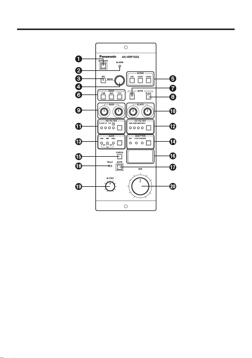
Major operating controls and their functions
Operation panel
OPERATE switch [OPERATE]
This switch allows operations to be performed using the controls on the remote control
panel. Its lamp lights up as soon as the power is turned on.
Lighted: The switch lamp lights up when the power is turned on.
When communication with the camera is enabled, switch selection is
set.
Extinguished: If the power has been turned on and the camera’s power is on, the
operations will be canceled (set to the protected status).
Alarm indicator [ALARM]
This lights up red when the camera’s fan has shut down. Normally, it goes off.
MENU ON/OFF switch [MENU ON]
This is used to display the menus on the main line images.

- 8 (E) -
ENGLISH
Major operating controls and their functions
Menu switch [MENU]
When this switch is rotated, menu items can be selected and data changed.
When it is pressed, items can be verified and data entered.
Scene file switches [SCENE PRE, USER1, USER2]
These switches are used to call the scene file data registered by the camera.
Camera video output selector switches [MODE CAM/BAR/TEST]
These switches are used to select the camera video output. Camera video, color bar
display or test display is selected.
CAM switch lamp lighted: Output of images shot by camera
BAR switch lamp lighted: Color bar output
TEST switch lamp lighted: Test signal output
Auto white balance switch [AUTO WHITE]
This switch is used for automatic white balance adjustments.
Switch lamp lights: When the switch is pressed, the start of the automatic white
balance operation is indicated by the lighting of the switch lamp.
Switch lamp flashes: If the white balance is not adjusted adequately upon completion
of the automatic white balance adjustment, the lamp flashes to
warn the user.
Switch lamp goes off: The lamp goes off when the white balance has been adjusted
satisfactorily.
Auto black balance switch [AUTO BLACK]
This switch is used for automatic black balance adjustments.
Switch lamp lights: When the switch is pressed, the start of the automatic black
balance operation is indicated by the lighting of the switch lamp.
Switch lamp flashes: If the black balance is not adjusted adequately upon completion
of the automatic black balance adjustment, the lamp flashes to
warn the user.
Switch lamp goes off: The lamp goes off when the black balance has been adjusted
satisfactorily.
R/B gain control [GAIN]
This control is used to adjust the red (R) and blue (B) of the white balance. Automatic
white balance operations can be performed while these colors are being adjusted.
R/B pedestal control [BLACK]
This control is used to adjust the red (R) and blue (B) of the pedestal. Automatic black
balance operations can be performed while these colors are being adjusted.
- 9 (E) -
ND filter switch [ND FILTER]
This switch is used to select the ND filter setting.
ND_1: CLEAR
ND_2: 1/4
ND_3: 1/16
ND_4: 1/32 or 1/64
The ND filter differs depending on the camera concerned. For details, refer to the camera’s
instruction manual.
CC filter switch [CC FILTER]
This switch is used to select the CC filter selection.
CC_A: 3200K
CC_B: 4300K
CC_C: 6300K
CC_D: Cross screen
This function does not work with AK-HC1500G.
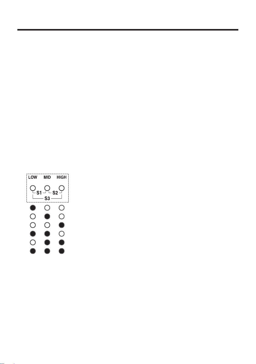
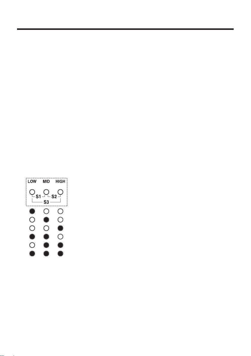
Gain switching status display [GAIN]
This indicates the gain of the video input sensitivity.
LOW gain status
MID gain status
HIGH gain status
Super gain 1 status
Super gain 2 status
Super gain 3 status
Electronic shutter switch [SHUTTER]
This switch is used to set the step shutter or synchro scan shutter set using the camera
menu to ON or OFF. The switch lamp lights when one of the shutters is selected.
Major operating controls and their functions

- 10 (E) -
ENGLISH
Iris f-number, master pedestal display selector switch [CHECK]
This switch is used to toggle between the f-number display and master pedestal display.
Iris f-number, master pedestal indicator
This indicator displays figures for the iris f-number and master pedestal.
Auto iris switch [AUTO]
This switch is used to turn on the auto iris function.
Switch lamp lighted: Auto iris status
Tally indicator [TALLY]
This lights when the tally input (MAKE) is supplied to the tally connector.
Master pedestal control [M-PED]
This control is used to adjust the master pedestal level. When it is turned clockwise, the
master pedestal level increases.
Iris control [IRIS]
This control is used to adjust the lens iris level.
Major operating controls and their functions
- 11 (E) -
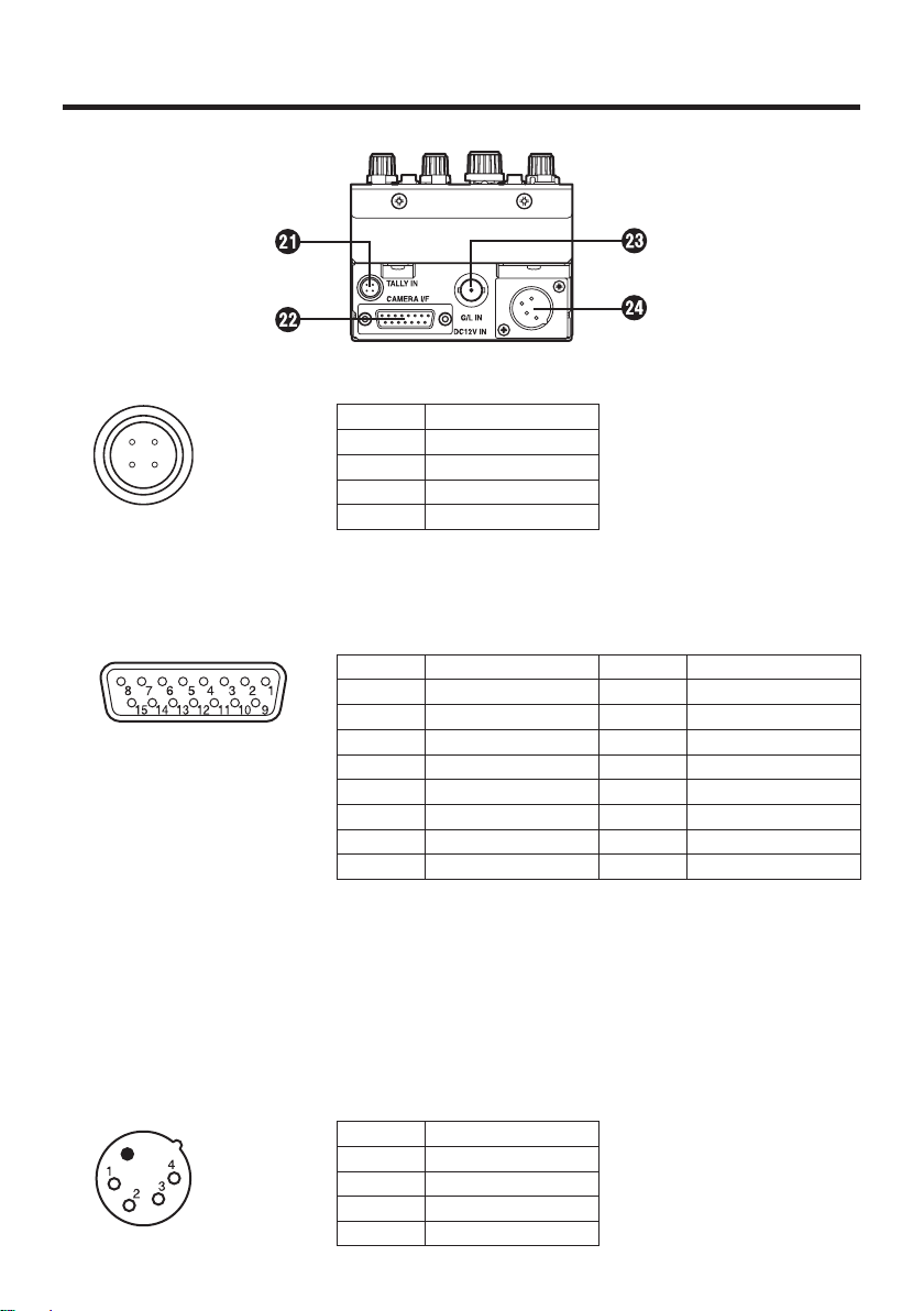
Major operating controls and their functions
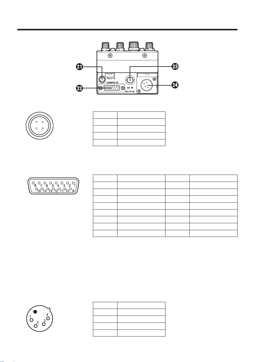
Rear panel
Tally signal input connector [TALLY IN]
Pin No. Signal
1 R TALLY
2 N.C.
3 N.C.
4 R TALLY COM
Camera I/F connector [CAMERA I/F]
Connected to the camera (AK-HC1500G) with the attached multi cable.
Pin No. Signal Pin No. Signal
1 — 9 —
2 — 10 —
3 — 11 G/L GND
4 G/L output 12 DC12 V GND
5 DC12 V output 13 TX_N output
6 GND 14 RX_P input
7 TX_P output 15 RX_N input
8 —
TXD: Data from camera to remote controller.
RXD: Data from remote controller to camera.
Synch signal input connector [G/L IN]
Inputs the sync signal to the camera.
DC12 V input connector [DC12V IN] (XLR4-pin)
Connects the AC adapter. We recommend that the AW-PS505A (sold separately) is
used.
Pin No. Signal
1 GND
2 N.C.
3 N.C.
4 DC12V
- 12 (E) -
ENGLISH
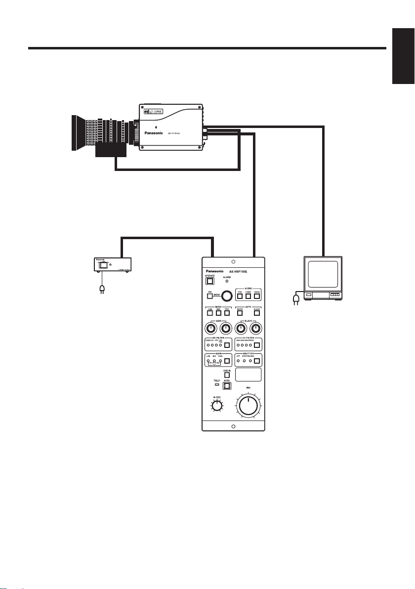
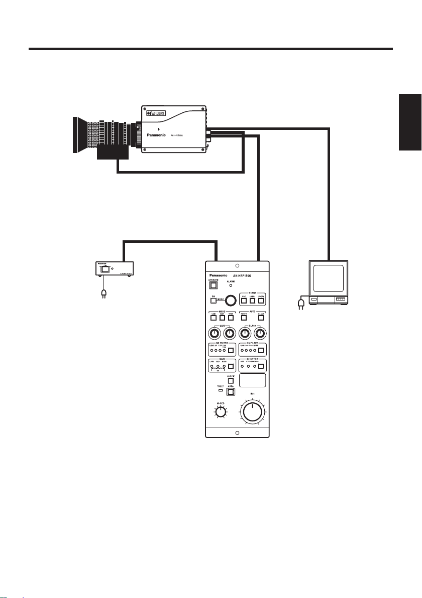
Multi purpose camera control system configuration
Lens
Multi purpose camera
AK-HC1500G
Camera controller
AK-HRP150G
AC adapter
AW-PS505A
Monitor
HD SDI OUT
IRIS
Multi cable
(POWER + CONTROL)
- 13 (E) -
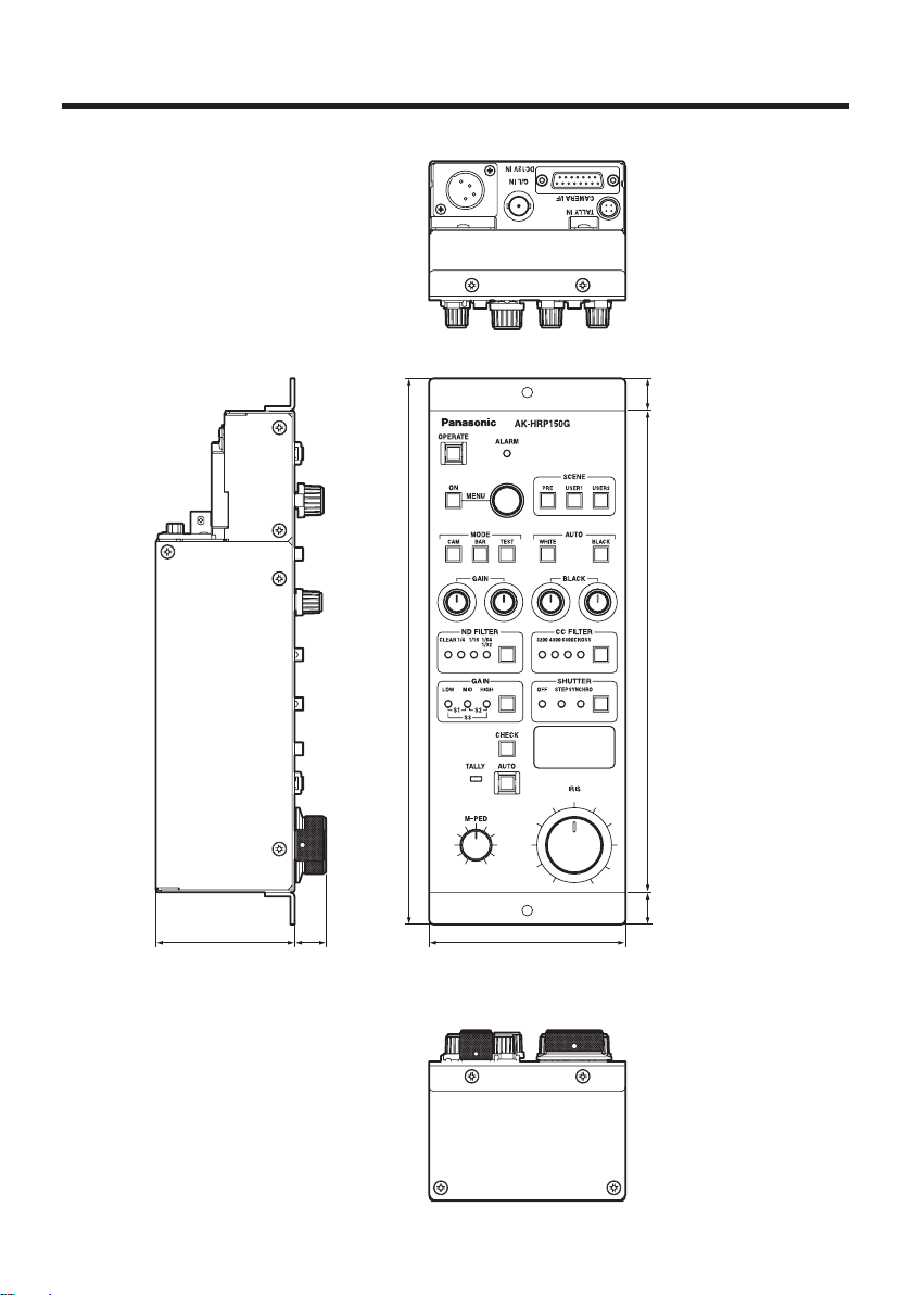
Appearance
3-5/8 (92)2-9/16 (65) 9/16
(15)
10-1/16 (255)
8-7/8 (225)
9/16
(15)
9/16
(15)
Unit: inch (mm)

- 14 (E) -
ENGLISH
Specifications
System tally input: Tally signal (HIROSE: HR10A-7R-4P)
Switch function: Menu ON/OFF, menu operation, operation panel active,
scene file select, mode select, auto white start, auto black start,
ND filter select, CC filter select, gain select, shutter select,
lens iris auto/manual select, indication change
Adjusting function: Iris (lens iris), R/B gain, master pedestal, R/B pedestal
Connection cable: Multi cable (1 pc)
Operating temperature range:
32°F to 104°F (0°C to +40°C)
Weight: Approx. 2.65 lbs. (1.2 kg)
Dimensions (WHD): 3-5/8”10-1/16”2-9/16” (9225565 mm)
(excluding protrusions)
Weight and dimensions shown are approximate.
Specifications are subject to change without notice.
Source voltage: 12 V DC (XLR 4-pin connector)
Power consumption: 3 W (Camera controller only)
indicates safety information.
- 1 (G) -
ist die Sicherheitsinformation.
VORSICHT:
NUR DAS EMPFOHLENE ZUBEHÖR VERWENDEN, UM DIE GEFAHR
VON FEUER UND ELEKTRISCHEM SCHLAG SOWIE STÖRUNGEN
AUSZUSCHALTEN.
Hinweis:
Das Typenschild (Seriennummerschild) befindet sich an der Unterseite
des Gerätes.
WARNUNG:
• UM BRAND- ODER STROMSCHLAGGEFAHR ZU REDUZIEREN, DARF
DIESES GERÄT WEDER REGEN NOCH NÄSSE AUSGESETZT WERDEN.
• SETZEN SIE DAS GERÄT KEINEM TROPF- ODER SPRITZWASSER
AUS, UND STELLEN SIE KEINE MIT FLÜSSIGKEITEN GEFÜLLTE
GEGENSTÄNDE, WIE Z.B. VASEN, AUF DAS GERÄT.
Öffnen Sie nicht das Gerät durch Abschrauben von Gehäuseteilen.
Zur Vermeidung von elektrischem Schlag darf das Gehäuse nicht geöffnet
werden. Im Geräteinneren befinden sich keine Teile, die vom Benutzer gewartet
werden können.
Wartungs - und Re parat urarbe iten gr undsät zlich a utorisi er tem
Kundendienstpersonal überlassen.
DEUTSCHE AUSGABE
(GERMAN VERSION)
- 2 (G) -
DEUTSCH
Benutzerinformationen zur Entsorgung von elektrischen und elektronischen
Geräten (private Haushalte)
Dieses Symbol auf Produkten und/oder begleitenden Dokumenten
bedeutet, dass verbrauchte elektrische und elektronische Produkte nicht mit
gewöhnlichem Haushaltsabfall vermischt werden sollen.
Bringen Sie zur ordnungsgemäßen Behandlung, Rückgewinnung und Recycling
diese Produkte zu den entsprechenden Sammelstellen, wo sie ohne Gebühren
entgegengenommen werden. In einigen Ländern kann es auch möglich sein,
diese Produkte beim Kauf eines entsprechenden neuen Produkts bei Ihrem
örtlichen Einzelhändler abzugeben.
Die ordnungsgemäße Entsorgung dieses Produkts dient dem Umweltschutz und
verhindert mögliche schädliche Auswirkungen auf Mensch und Umgebung, die aus einer
unsachgemäßen Handhabung von Abfall entstehen können.
Genauere Informationen zur nächstgelegenen Sammelstelle erhalten Sie bei Ihrer
Gemeindeverwaltung.
In Übereinstimmung mit der Landesgesetzgebung können für die unsachgemäße Entsorgung
dieser Art von Abfall Strafgebühren erhoben werden.
Für Geschäftskunden in der Europäischen Union
Bitte treten Sie mit Ihrem Händler oder Lieferanten in Kontakt, wenn Sie elektrische und
elektronische Geräte entsorgen möchten. Er hält weitere Informationen für sie bereit.
Informationen zur Entsorgung in anderen Ländern außerhalb der
Europäischen Union
Dieses Symbol ist nur in der Europäischen Union gültig.
Bitte treten Sie mit Ihrer Gemeindeverwaltung oder Ihrem Händler in Kontakt, wenn Sie dieses
Produkt entsorgen möchten, und fragen Sie nach einer Entsorgungsmöglichkeit.

- 3 (G) -
Inhalt
Zubehör
Einleitung ........................................................................................................................... 3
Zubehör .............................................................................................................................. 3
Vorsichtsmaßnahmen zum Gebrauch
............................................................................. 4
Wichtige Bedienungselemente und ihre Funktionen
..................................................... 5
Konfiguration des Mehrzweckkamera-Steuersystems
................................................ 10
Aussehen
......................................................................................................................... 11
Technische Daten
............................................................................................................ 12
Multikabel (5 m) ..................................... 1
Befestigungsschrauben (M4
8 mm) ... 2
Einleitung
Dieses Gerät ist ein Kamerasteuergerät für Mehrzweckkameras (AK-HC1500G).
Es wird über ein Multikabel an eine Mehrzweckkamera angeschlossen und ist in der Lage,
verschiedene Kamera- und Objektivsteuersignale sowie Genlocksignale (3-Wert SYNC/
BB-SYNC) zu übertragen und zu empfangen.

- 4 (G) -
DEUTSCH
Wir empfehlen die Verwendung des Netzgerätes AW-PS505A als Stromquelle.
Behandeln Sie das Steuergerät sorgfältig.
Fallenlassen oder starke Erschütterungen des Steuergerätes können eine
Funktionsstörung oder Unfälle verursachen.
Benutzen Sie das Steuergerät bei einer Umgebungstemperatur von 0°C bis 40°C.
Bei Benutzung des Steuergerätes an kalten Orten (unter 0°C) oder heißen Orten (über
40°C) können seine Innenteile beeinträchtigt werden.
Schalten Sie vor dem Anschließen oder Abtrennen der Kabel die
Stromversorgung aus.
Schalten Sie das Gerät unbedingt aus, bevor Sie die Kabel anschließen oder abtrennen.
Vermeiden Sie die Benutzung des Gerätes im Freien.
Installieren Sie das Gerät mindestens 1 m vom Monitor entfernt.
Wartung
Wischen Sie das Steuergerät mit einem trockenen Tuch ab. Um hartnäckigen Schmutz
zu entfernen, tauchen Sie ein Tuch in verdünnte Haushaltsreinigerlösung, wringen Sie
es gut aus, und wischen Sie dann das Steuergerät sachte ab.
Vorsichtsmaßnahmen zum Gebrauch
Vorsicht
Vermeiden Sie Benzin, Lackverdünner und andere leichtflüchtige Flüssigkeiten.
Wenn Sie ein chemisches Reinigungstuch verwenden wollen, lesen Sie die
Gebrauchsanleitung sorgfältig durch.
- 5 (G) -
Wichtige Bedienungselemente und ihre Funktionen
Bedienungstafel
Betriebstaste [OPERATE]
Diese Taste ermöglicht die Durchführung von Bedienungsvorgängen mit den
Bedienelementen am Fernsteuerpult. Ihre Lampe leuchtet auf, sobald die
Stromversorgung eingeschaltet wird.
Erleuchtet
: Die Tastenlampe leuchtet auf, wenn die Stromversorgung eingeschaltet
wird.
Wenn die Kommunikation mit der Kamera möglich ist, ist die Tastenwahl
aktiviert.
Erloschen
: Wenn das Steuergerät eingeschaltet worden ist und die Kamera
eingeschaltet ist, werden die Operationen gesperrt (Schutzzustand
aktiviert).
Alarmlampe [ALARM]
Diese Lampe leuchtet auf, wenn der Lüfter der Kamera stehen bleibt. Normalerweise ist
diese Lampe erloschen.
Menü-Ein/Aus-Taste [MENU ON]
Dient zur Anzeige der Menüs in den Bildern der Hauptleitung.

- 6 (G) -
DEUTSCH
Wichtige Bedienungselemente und ihre Funktionen
Menüknopf [MENU]
Durch Drehen dieses Knopfes können Menüposten ausgewählt und Daten geändert
werden.
Durch Drücken des Knopfes können Posten bestätigt und Daten eingegeben werden.
Szenendateitasten [SCENE PRE, USER1, USER2]
Diese Tasten dienen zum Aufrufen der in der Kamera registrierten Szenendateidaten.
Kamera-Videoausgangswahltasten [MODE CAM/BAR/TEST]
Diese Tasten dienen zur Wahl der Kamera-Videoausgabe. Zur Auswahl stehen
Kameravideo, Farbbalkenanzeige und Testsignalanzeige.
Lampe der Taste CAM leuchtet
: Ausgabe der Kamerabilder
Lampe der Taste BAR leuchtet
: Ausgabe der Farbbalken
Lampe der Taste TEST leuchtet
: Ausgabe des Testsignals
Weißabgleich-Automatiktaste [AUTO WHITE]
Diese Taste dient zur Durchführung automatischer Weißabgleich-Einstellungen.
Tastenlampe leuchtet
: Wenn die Taste gedrückt wird, wird der Start der
automatischen Weißabgleichoperation durch Aufleuchten der
Tastenlampe angezeigt.
Tastenlampe blinkt
: Falls mit der automatischen Weißabgleich-Einstellung kein
korrekter Weißabgleich erzielt werden konnte, blinkt die
Lampe, um den Benutzer zu warnen.
Tastenlampe erloschen
: Die Lampe erlischt, wenn der Weißabgleich zufrieden
stellend durchgeführt worden ist.
Schwarzabgleich-Automatiktaste [AUTO BLACK]
Diese Taste dient zur Durchführung automatischer Schwarzabgleich-Einstellungen.
Tastenlampe leuchtet
: Wenn die Taste gedrückt wird, wird der Start der
automatischen Schwarzabgleichoperation durch Aufleuchten
der Tastenlampe angezeigt.
Tastenlampe blinkt
: Falls mit der automatischen Schwarzabgleich-Einstellung
kein korrekter Schwarzabgleich erzielt werden konnte, blinkt
die Lampe, um den Benutzer zu warnen.
Tastenlampe erloschen
: Die Lampe erlischt, wenn der Schwarzabgleich zufrieden
stellend durchgeführt worden ist.
R/B-Verstärkungsregler [GAIN]
Diese Regler dienen zur Einstellung der Farben Rot (R) und Blau (B) des
Weißabgleichs. Automatische Weißabgleichoperationen können durchgeführt werden,
während diese Farben eingestellt werden.
R/B-Schwarzwertregler [BLACK]
Diese Regler dienen zur Einstellung der Farben Rot (R) und Blau (B) des Schwarzwerts.
Automatische Schwarzabgleichoperationen können durchgeführt werden, während
diese Farben eingestellt werden.
- 7 (G) -
ND-Filter-Taste [ND FILTER]
Diese Taste dient zur Wahl der ND-Filter-Einstellung.
ND_1: CLEAR
ND_2: 1/4
ND_3: 1/16
ND_4: 1/32 or 1/64
Der ND-Filter ist je nach der betreffenden Kamera unterschiedlich. Einzelheiten
entnehmen Sie bitte der Bedienungsanleitung der Kamera.
CC-Filter-Taste [CC FILTER]
Diese Taste dient zur Wahl der CC-Filter-Einstellung.
CC_A: 3200K
CC_B: 4300K
CC_C: 6300K
CC_D: Cross screen
Diese Funktion ist mit AK-HC1500G unwirksam.
Verstärkungsstatusanzeige [GAIN]
Diese Anzeige gibt Aufschluss über den Verstärkungsstatus der Videoeingangsempfind
lichkeit.
Status der niedrigen Verstärkung (LOW)
Status der mittleren Verstärkung (MID)
Status der hohen Verstärkung (HIGH)
Status der Superverstärkung 1
Status der Superverstärkung 2
Status der Superverstärkung 3
Elektronikverschlusstaste [SHUTTER]
Diese Taste dient zur Einstellung des Postens Step Shutter oder Synchro Scan Shutter
Set im Kameramenü auf ON oder OFF. Die Tastenlampe leuchtet auf, wenn einer der
Verschlüsse gewählt wird.
Wichtige Bedienungselemente und ihre Funktionen

- 8 (G) -
DEUTSCH
Blendenwert-, Master-Schwarzwertanzeige-Wahltaste [CHECK]
Diese Taste dient zum Umschalten zwischen Blendenwertanzeige und MasterSchwarzwertanzeige.
Blendenwert-, Master-Schwarzwertanzeige
Diese Anzeige zeigt die Zahlen für den Blendenwert und den Master-Schwarzwert an.
Blendenautomatiktaste [AUTO]
Diese Taste dient zum Aktivieren der Blendenautomatikfunktion.
Tastenlampe erleuchtet
: Blendenautomatikstatus
Tally-Lampe [TALLY]
Diese Lampe leuchtet auf, wenn das Tally-Eingangssignal (MAKE) der TallysignalEingangsbuchse zugeführt wird.
Master-Schwarzwertregler [M-PED]
Dieser Regler dient zum Einstellen des Master-Schwarzwertpegels. Durch Drehen im
Uhrzeigersinn wird der Master-Schwarzwertpegel erhöht.
Blendenregler [IRIS]
Dieser Regler dient zum Einstellen der Blendenstufe des Objektivs.
Wichtige Bedienungselemente und ihre Funktionen
- 9 (G) -
Wichtige Bedienungselemente und ihre Funktionen
Rückwand
Tallysignal-Eingangsbuchse [TALLY IN]
Stift-Nr. Signal
1 R TALLY
2 N.C
3 N.C.
4 R TALLY COM
Kamera-Schnittstellenanschluss [CAMERA I/F]
Dieser Anschluss wird über das mitgelieferte Multikabel mit der Kamera (AK-HC1500G)
verbunden.
Stift-Nr. Signal Stift-Nr. Signal
1 — 9 —
2 — 10 —
3 — 11 G/L GND
4 G/L output 12 DC12 V GND
5 DC12 V output 13 TX_N output
6 GND 14 RX_P input
7 TX_P output 15 RX_N input
8 —
TXD: Daten von der Kamera zur Fernsteuerung.
RXD: Daten von der Fernsteuerung zur Kamera.
Syncsignal-Eingangsbuchse [G/L IN]
Dient zur Einspeisung des Syncsignals in die Kamera.
12-V-Gleichstromeingang [DC12V IN] (XLR 4-polig)
Hier wird das Netzgerät angeschlossen. Wir empfehlen die Verwendung des
AW-PS505A (getrennt erhältlich).
Stift-Nr. Signal
1 GND
2 N.C.
3 N.C.
4 DC12V
- 10 (G) -
DEUTSCH
Konfiguration des Mehrzweckkamera-Steuersystems
Objektiv
Mehrzweckkamera
AK-HC1500G
Kamerasteuergerät
AK-HRP150G
Netzgerät
AW-PS505A
Monitor
HD SDI OUT
IRIS
Multikabel
(POWER + CONTROL)

- 11 (G) -
Aussehen
9265 15
255
225
15 15
Einheit: mm

- 12 (G) -
DEUTSCH
Technische Daten
System-Tallyeingang: Tallysignal (HIROSE: HR10A-7R-4P)
Schalterfunktionen: Menü EIN/AUS, Menüoperation, Bedienungstafel aktiv,
Szenendateiwahl, Moduswahl,
Start der Weißabgleichautomatik,
Start der Schwarzabgleichautomatik, ND-Filterwahl,
CC-Filterwahl, Verstärkungswahl, Verschlusswahl,
Wahl der automatischen/manuellen
Objektivblendeneinstellung, Anzeigenumschaltung
Einstellfunktionen: Blende (Objektivblende), R/B-Verstärkung,
Master-Schwarzwert, R/B-Schwarzwert
Verbindungskabel: Multikabel (1 Stück)
Betriebstemperaturbereich:
0°C bis +40°C
Gewicht:
ca. 1,2 kg
Abmessungen (B
HT): 9225565 mm (ohne Vorsprünge)
Bei den obigen Gewichts- und Abmessungsangaben handelt es sich um Näherungswerte.
Änderungen der technischen Daten vorbehalten.
Versorgungsspannung:
12 V Gleichstrom (4-poliger XLR-Anschluss)
Leistungsaufnahme: 3 W (nur Kamerasteuergerät)
ist die Sicherheitsinformation.
- 1 (F) -
Informations concernant la sécurité.
ATTENTION:
POUR ÉVITER TOUT RISQUE D’INCENDIE, DE CHOCS ÉLECTRIQUES OU
D’INTERFÉRENCES, N’UTILISER QUE LES ACCESSOIRES RECOMMANDÉS.
Remarque:
La plaque signalétique (plaque du numéro de série) est située sur la face
inférieure de l’appareil.
AVERTISSEMENT:
• POUR RÉDUIRE LES RISQUES D’INCENDIE OU D’ÉLECTROCUTION, NE
PAS EXPOSER CET APPAREIL À LA PLUIE OU À L’HUMIDITÉ.
• CET APPAREIL NE DOIT PAS ÊTRE EXPOSÉ À DES SUINTEMENTS OU
DES ÉCLABOUSSURES, ET AUCUN OBJET REMPLI DE LIQUIDE, COMME
UN VASE, NE DOIT ÊTRE POSÉ DESSUS.
Ne pas dévisser le couvercle.
Pour réduire tout risque d’électrocution, ne pas retirer le couvercle. Il ne se
trouve à l’intérieur aucune pièce qui puisse être réparée par l’utilisateur.
Confier toute réparation à un personnel qualifié.
VERSION FRANÇAISE
(FRENCH VERSION)
- 2 (F) -
FRANÇAIS
Informations relatives à l’évacuation des déchets, destinées aux utilisateurs
d’appareils électriques et électroniques (appareils ménagers domestiques)
Lorsque ce symbole figure sur les produits et/ou les documents qui les
accompagnent, cela signifie que les appareils électriques et électroniques ne
doivent pas être jetés avec les ordures ménagères.
Pour que ces produits subissent un traitement, une récupération et un recyclage
appropriés, envoyez-les dans les points de pré-collecte désignés, où ils peuvent
être déposés gratuitement. Dans certains pays, il est possible de renvoyer les
produits au revendeur local en cas d’achat d’un produit équivalent.
En éliminant correctement ce produit, vous contriburez à la conservation des ressources
vitales et à la prévention des éventuels effets négatifs sur l’environnement et la santé
humaine, pouvant être dus à la manipulation inappropriée des déchets.
Veuillez contacter les autorités locales pour connaître le point de pré-collecte le plus proche.
Des sanctions peuvent être appliquées en cas d’élimination incorrecte de ces déchets,
conformément à la législation nationale.
Utilisateurs professionnels de l’Union européenne
Pour en savoir plus sur l’élimination des appareils électriques et électroniques, contactez votre
revendeur ou fournisseur.
Informations sur l’évacuation des déchets dans les pays ne faisant pas partie
de l’Union européenne
Ce symbole n’est reconnu que dans l’Union européenne.
Pour supprimer ce produit, contactez les autorités locales ou votre revendeur afin de connaître
la procédure d’élimination à suivre.

- 3 (F) -
Table des matières
Accessoires
Introduction ........................................................................................................................ 3
Accessoires ........................................................................................................................ 3
Précautions d’utilisation ................................................................................................... 4
Principaux organes de commande et leurs fonctions
................................................... 5
Configuration du système de commande de la caméra multi-usages
....................... 10
Aspect extérieur
.............................................................................................................. 11
Fiche technique
............................................................................................................... 12
Multi câble (5 m) .....................................
1
Vis de fixation (M48 mm) ................... 2
Introduction
Cet appareil est une unité de commande de caméra pour caméra multi-usages
(AK-HC1500G), auquel il est raccordé au moyen d’un multi câble.
Il est capable de transmettre et de recevoir des signaux de commande de caméra et
d’objectif variés ainsi que des signaux de verrouillage de synchronisation (3 valeurs SYNC/
BB-SYNC).