

Panasonic ak-hc3800 Operation Manual
Operating Instructions
Studio Handy Camera
Model No.
AK-HC3800G/GS
DEUTSCH
FRANÇAIS
ITALIANO
ESPAÑOL
日本語
This manual is also contained as a PDF file on the CD-ROM supplied with the unit. (→ page 5)
Before operating this product, please read the instructions carefully and save this manual for future use.
Für Erlauterungen in Deutsch, konsultieren Sie bitte die mitgelieferte CD-ROM.
(→ Seite 5)
Pour des explications en français, veuillez vous reporter au CD-ROM fourni.
(→ page 5)
Per le istruzioni in italiano, vedere il CD-ROM in dotazione. (→ pagina 5)
Para la explicación en español, consulte el CD-ROM suministrado. (→ página 5)
日本語版の取扱説明書は付属のCD-ROMに納められています。(→5ページ)
FJ1012KT0 -PS
Printed in Japan
ENGLISH
VQT4Q11
3
Read this first!
CAUTION
RISK OF ELECTRIC SHOCK
DO NOT OPEN
CAUTION: TO REDUCE THE RISK OF ELECTRIC SHOCK,
REFER TO SERVICING TO QUALIFIED SERVICE PERSONNEL.
DO NOT REMOVE COVER (OR BACK).
NO USER SERVICEABLE PARTS INSIDE.
The lightning flash with arrowhead symbol,
within an equilateral triangle, is intended to
alert the user to the presence of uninsulated
“dangerous voltage” within the product’s
enclosure that may be of sufficient magnitude
to constitute a risk of electric shock to persons.
The exclamation point within an equilateral
triangle is intended to alert the user to
the presence of important operating and
maintenance (servicing) instructions in the
literature accompanying the appliance.
WARNING:
This equipment must be earthed.
To ensure safe operation, make sure that the optical cable is
securely connected to an earthed CCU when in use.
The fact that the equipment operates satisfactorily does not imply
that the power point is earthed or that the installation is completely
safe. For your safety, if you are in any doubt about the effective
earthing of the power point, please consult a qualified electrician.
CAUTION:
The optical cable shall remain readily operable.
To completely disconnect this equipment from the power supply,
disconnect the optical cable from the equipment.
CAUTION:
To reduce the risk of fire or electric shock and annoying
interference, use the recommended accessories only.
CAUTION:
Excessive sound pressure from earphones and headphones can
cause hearing loss.
CAUTION:
Invisible Laser radiation is emitted from the Optical fiber connector
when this product is turned on.
Don’t look into directly into the Optical fiber connector of this
product.
CAUTION:
Do not jar, swing, or shake the unit by its handle while another
accessory is attached.
Due to the added weight, any strong jolt to the handle may
damage the unit or result in personal injury.
CAUTION:
Do not lift the unit by its handle while the tripod is attached. When
the tripod is attached, its weight will also affect the unit’s handle,
possibly causing the handle to break and hurting the user. To
carry the unit while the tripod is attached, take hold of the tripod.
WARNING:
• To reduce the risk of fire or electric shock, do not expose this
equipment to rain or moisture.
• To reduce the risk of fire or electric shock, keep this equipment
away from all liquids. Use and store only in locations which are
not exposed to the risk of dripping or splashing liquids, and do
not place any liquid containers on top of the equipment.
WARNING:
Always keep memory cards (optional accessory) or accessories
(camera number sheet) out of the reach of babies and small
children.
CAUTION:
Do not remove panel covers by unscrewing.
To reduce the risk of electric shock, do not remove the covers. No
user serviceable parts inside.
Refer servicing to qualified service personnel.
CAUTION:
In order to maintain adequate ventilation, do not install or place
this unit in a bookcase, built-in cabinet or any other confined
space. To prevent risk of electric shock or fire hazard due to
overheating, ensure that curtains and any other materials do not
obstruct the ventilation.
indicates safety information.
CAUTION:
Do not leave the unit in direct contact with the skin for long periods
of time when in use.
Low temperature burn injuries may be suffered if the high
temperature parts of this unit are in direct contact with the skin for
long periods of time.
When using the equipment for long periods of time, make use of
the tripod.
CAUTION:
This product uses a semiconductor laser system and is a laser
class 1 product complies with Radiation Performance Standards,
21CFR SUBCHAPTER J.
Use of controls or adjustments or performance of procedures
other than those specified herein may result in hazardous
radiation exposure.
Don’t make any modifications.
Don’t repair by yourself.
Refer servicing to qualified personnel.
2

Read this first! (continued)
FCC NOTICE(USA)
This device complies with part 15 of the FCC Rules. Operation is subject to the following two conditions:
(1) This device may not cause harmful interference, and (2) this device must accept any interference received, including interference that may
cause undesired operation
CAUTION:
This equipment has been tested and found to comply with the limits for a class A digital device, pursuant to Part 15 of the FCC Rules.
These limits are designed to provide reasonable protection against harmful interference when the equipment is operated in a commercial
environment. This equipment generates, uses, and can radiate radio frequency energy and, if not installed and used in accordance with the
instruction manual, may cause harmful interference to radio communications.
Operation of this equipment in a residential area is likely to cause harmful interference in which case the user will be required to correct the
interference at his own expense.
FCC Warning:
To assure continued FCC emission limit compliance, follow the attached installation instructions and the user must use only shielded interface
cables when connecting to host computer or peripheral devices.
Also, any unauthorized changes or modifications to this equipment could void the user’s authority to operate this device.
NOTIFICATION(Canada)
This class A digital apparatus complies with Canadian ICES-003.
indicates safety information.
EEE Yönetmeliğine Uygundur.
EEE Complies with Directive of Turkey.
EU
Importer’s name and address of pursuant to EU rules:
Panasonic Testing Centre
Panasonic Marketing Europe GmbH
Winsbergring 15, 22525 Hamburg, Germany

Read this first! (continued)
5
EMC NOTICE FOR THE PURCHASER/USER OF THE APPARATUS
1. Applicable standards and operating environment (AK-HC3800)
The apparatus is compliant with:
• standards EN55103-1 and EN55103-2 2009, and
• electromagnetic environments E1 - E5.
2. Pre-requisite conditions to achieving compliance with the above standards
<1> Peripheral equipment to be connected to the apparatus and special connecting cables
• The purchaser/user is urged to use only equipment which has been recommended by us as peripheral equipment to be connected to the
apparatus.
• The purchaser/user is urged to use only the connecting cables described below.
<2> For the connecting cables, use shielded cables which suit the intended purpose of the apparatus.
• Video signal connecting cables
Use double shielded coaxial cables, which are designed for 75-ohm type high-frequency applications, for SDI (Serial Digital Interface).
Coaxial cables, which are designed for 75-ohm type high-frequency applications, are recommended for analog video signals.
• Audio signal connecting cables
If your apparatus supports AES/EBU serial digital audio signals, use cables designed for AES/EBU.
Use shielded cables, which provide quality performance for high-frequency transmission applications, for analog audio signals.
• Other connecting cables
Use shielded cables, which provide quality performance for high-frequency applications, as connecting cables.
• When connecting to the DVI signal terminal, use a cable with a ferrite core.
• If your apparatus is supplied with ferrite core(s), they must be attached on cable(s) following instructions in this manual.
3. Performance level
The performance level of the apparatus is equivalent to or better than the performance level required by these standards.
However, the apparatus may be adversely affected by interference if it is being used in an EMC environment, such as an area where strong
electromagnetic fields are generated (by the presence of signal transmission towers, cellular phones, etc.). In order to minimize the adverse
effects of the interference on the apparatus in cases like this, it is recommended that the following steps be taken with the apparatus being
affected and with its operating environment:
1. Place the apparatus at a distance from the source of the interference.
2. Change the direction of the apparatus.
3. Change the connection method used for the apparatus.
4. Connect the apparatus to another power outlet where the power is not shared by any other appliances.
Вимогам Технічного Регламенту Обмеження Використання деяких Небезпечних Речовин в електричному та електронному обладнанні
(затвердженого Постановою №1057 Кабінету Міністрів України)
Виріб відповідає вимогам Технічного Регламенту Обмеження Використання деяких Небезпечних Речовин в електричному та електронному
обладнанні (ТР ОВНР).
Вміст небезпечних речовин у випадках, не обумовлених в Додатку №2 ТР ОВНР, :
1. свинець(Pb) – не перевищує 0,1 % ваги речовини або в концентрації до 1000 частин на мільйон;
2. кадмій (Cd)– не перевищує 0,01 % ваги речовини або в концентрації до 100 частин на мільйон;
3. ртуть(Hg) – не перевищує 0,1 % ваги речовини або в концентрації до 1000 частин на мільйон;
4. шестивалентний хром (Cr6+ ) – не перевищує 0,1 % ваги речовини або в концентрації до 1000 частин на мільйон;
5. полібромбіфеноли (PBB) – не перевищує 0,1% ваги речовини або в концентрації до 1000 частин на мільйон;
6. полібромдефенілові ефіри (PBDE) – не перевищує 0,1 % ваги речовини або в концентрації до 1000 частин на мільйон.
Декларація про Відповідність
IMPORTANT SAFETY INSTRUCTIONS
1) Read these instructions.
2) Keep these instructions.
3) Heed all warnings.
4) Follow all instructions.
5) Do not use this apparatus near water.
6) Clean only with dry cloth.
7) Do not block any ventilation openings. Install in accordance with the manufacturer’s instructions.
8) Do not install near any heat sources such as radiators, heat registers, stoves, or other apparatus (including amplifiers) that produce heat.
9) Do not defeat the safety purpose of the polarized or grounding-type plug. A polarized plug has two blades with one wider than the other. A
grounding-type plug has two blades and a third grounding prong. The wide blade or the third prong are provided for your safety. If the provided plug
does not fit into your outlet, consult an electrician for replacement of the obsolete outlet.
10) Protect the power cable from being walked on or pinched particularly at plugs, convenience receptacles, and the point where they exit from the
apparatus.
11) Only use attachments/accessories specified by the manufacturer.
12) Use only with the cart, stand, tripod, bracket, or table specified by the manufacturer, or sold with the apparatus. When a cart is used,
use caution when moving the cart/apparatus combination to avoid injury from tip-over.
13) Unplug this apparatus during lightning storms or when unused for long periods of time.
14) Refer all servicing to qualified service personnel. Servicing is required when the apparatus has been damaged in any way, such as
power-supply cord or plug is damaged, liquid has been spilled or objects have fallen into the apparatus, the apparatus has been
exposed to rain or moisture, does not operate normally, or has been dropped.
4

Read this first! (continued)
ENGLISH
How to open the operating instruction manual PDF files
Discontinue installation if the installation screen of the software opens as
a result of inserting the CD-ROM.
When [INDEX.pdf] on the CD-ROM is opened, a list of the operating
instruction manuals will be displayed.
Click on the document name of the manual to be opened.
Adobe® Reader® is required to read PDF files.
It can be downloaded from the home page of Adobe
Systems.
DEUTSCH
Öffnen der PDF-Dateien der Bedienungsanleitung
Brechen Sie die Installation ab, falls beim Einlegen der CD-ROM der
Installationsbildschirm der Software erscheint.
Wenn [INDEX.pdf] auf der CD-ROM geöffnet wird, erscheint eine Liste
der Bedienungsanleitungen.
Klicken Sie auf den Dokumentennamen der zu öffnenden
Anleitung.
Zum Lesen der PDF-Dateien benötigen Sie Adobe®
®
Reader
Dieses Programm kann von der Homepage von Adobe
Systems heruntergeladen werden.
.
ITALIANO
Come aprire i file dei manuali di istruzioni per l’uso
Se inserendo il CD-ROM si apre la schermata di installazione del
software, interrompere l’installazione.
Aprendo [INDEX.pdf] sul CD-ROM, viene visualizzato un elenco di
manuali di istruzioni per l’uso.
Fare clic sul nome del documento corrispondente al manuale da aprire.
Per leggere i file PDF è necessario Adobe® Reader®.
Il programma può essere scaricato dal sito Web di Adobe
Systems.
ESPAÑOL
Modo de abrir los archivos PDF que contienen el manual
de las instrucciones de funcionamiento
Interrumpa la instalacion si la pantalla de instalacion del software se
abre como resultado de insertar el CD-ROM.
Cuando se abra [INDEX.pdf] en el CD-ROM se visualizara una lista de
los manuales de instrucciones de funcionamiento.
Haga clic en el nombre de documento del manual que va a abrir.
Para leer los archivos PDF se necesita el programa
®
Adobe
Este programa se puede descargar de la pagina inicial de
Adobe Systems.
Reader®.
FRANÇAIS
Comment ouvrir les fichiers PDF des manuels du mode
d’emploi
Arrêter l’installation si l’écran d’installation du logiciel s’ouvre quand le
CD-ROM est inséré.
Quand [INDEX.pdf] sur le CD-ROM s’ouvre, la liste des manuels du
mode d’emploi s’affiche.
Cliquer sur le nom du document correspondant au manuel à
consulter.
Adobe® Reader® est nécessaire pour lire les fichiers PDF.
Ce logiciel peut être téléchargé depuis la page d’accueil
d’Adobe Systems.
日本語
取扱説明書PDFファイルの聞き方
CD-ROMを挿入してソフトウエアのインストール画面が立ち上がる場
合は、インストールを中止してください。
CD-ROM内の[INDEX.pdf]を聞くと取扱説明書の一覧が表示されま
す。
開きたい取扱説明書のドキュメント名をクリックしてください。
PDFファイルをご覧いただくには、Adobe®Reader®が
必要です。
アドビシステムズ社のホームページからダウンロードしてく
ださい。
5

7
Contents
Read this first! .......................................................................................2
Introduction ............................................................................................6
Accessories ...........................................................................................6
Features.................................................................................................. 7
Frame frequency setting ....................................................................... 7
Precautions for use ............................................................................... 8
Parts and their functions ...................................................................... 9
Attaching/detaching the viewfinder .................................................. 14
Connecting a microphone .................................................................. 15
Component system configuration ..................................................... 16
AK-HC3800G/GS Connector Pins ......................................................17
Status displays on viewfinder screen ...............................................18
Checking the operating time .............................................................. 20
Warning displays ................................................................................. 20
Menu operations .................................................................................. 21
Menu configuration ............................................................................. 23
Table of the adjustment setting ranges ............................................. 25
Data handled in the camera ................................................................ 31
Updating the firmware in this unit .....................................................32
Dimensional outline drawing ..............................................................32
Specifications ...................................................................................... 33
Index ..................................................................................................... 34
Introduction
Request
This unit is shipped with the frame frequency set to 59.94 Hz. Follow the procedure on page 7 to change the frame
frequency to match the region of use.
This unit is a studio handy camera that supports the 1080i format. Combined use with Panasonic's peripheral equipment Camera Control Unit AKHCU200/S and Remote Operation Panel AK-HRP200G enables you to build an optical transmission studio camera system with high image quality
capable of uncompressed long-distance transmission at a low cost.
It uses a 2/3-type 2.2-megapixel IT-CCD imaging device in conjunction with a newly-developed 16-bit A/D digital signal processing circuit to achieve
higher sensitivity than conventional cameras. Furthermore, it includes new functions such as CAC (chromatic aberration compensation function to
compensate the chromatic aberration of the magnification of a lens) and scan reverse (a function to compensate the reverse video when using an
anamorphic lens and film lens), in addition to multi-functionality, high quality, and improved stable operability that can be achieved only by digital
processing.
About trademarks and registered trademarks
• Adobe® and Reader® are either registered trademarks or trademarks of Adobe Systems Incorporated in the United States and other countries.
• SDHC logo is a trademark of SD-3C, LLC.
• Company names, product names, and other names appearing in this manual are trademarks or registered trademarks of their respective
companies.
Illustrations and screen images in this manual
Illustrations of the camera unit and menu screens may appear different from the actual camera unit and menu screens.
Reference pages
Reference pages are indicated as (page 00) in this manual.
Terms
• "Memory card" is used to indicate both SD memory card and SDHC memory card.
• "CCU" is used to indicate camera control unit in this manual.
• "ROP" is used to indicate remote operation panel in this manual.
Accessories
Please check the accessories.
• Dispose of the package appropriately after unpacking the product.
CD-ROM ........................................................... 1
• Operating Instructions
Camera number sheet (1 to 12) ..................1 set
6
Lens mount cap ................................................. 1
4
3
2
1
8
7
6
5
12
11
10
9
(Already mounted to the main body)
Features
USER MENU
OPERATION
>MENTENANCE
MENTENANCE
SD CARD R/W
|
> SYSTEM
SYSTEM
> FORMAT 59.94i
|
1080i, 2.2-megapixel CCDs employed
• The standard sensitivity is F11 (F12 with 50 Hz). High sensitivity is
also achieved.
Furthermore, it can operate at 1080i (50 Hz/59.94 Hz switchable).
Digital signal processing with a 16-bit A/D converter
• A 16-bit A/D converter with a sampling frequency of 74 MHz converts
the video signals into digital signals to reproduce fine and high quality
images.
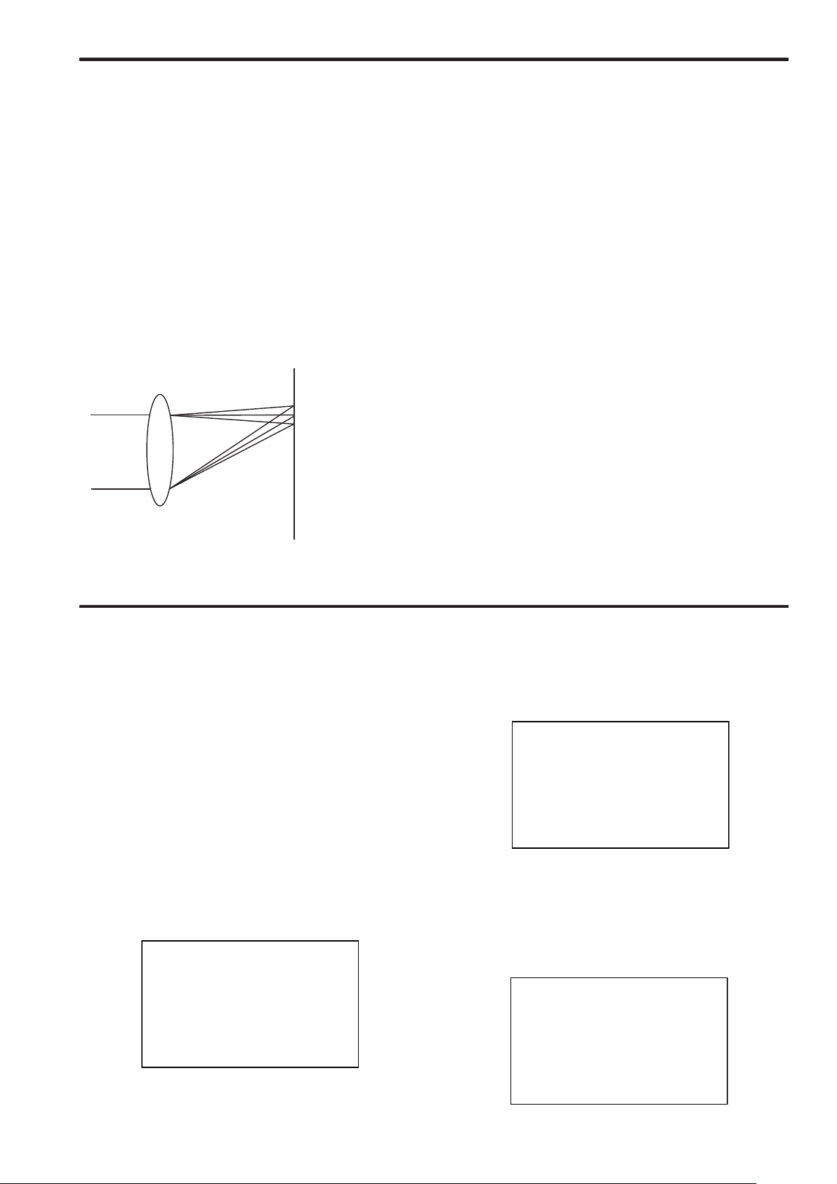
Chromatic Aberration Compensation (CAC) function
• This unit is equipped with a function to compensate the chromatic
aberration of the magnification of a lens caused by the fact that
the refractive index of a lens varies with the wavelength of light
(hereinafter referred to as the chromatic aberration).
The chromatic aberration of the magnification is caused by the
differences in the red (R), green (G), and blue (B) refractive indexes of
a lens. The lens itself corrects chromatic aberration but it remains, in
particular, in the surrounding area. Furthermore, the zooming ratio, iris,
and focal distance have a complicated relationship with this chromatic
aberration in the case of a zoom lens. Images have registration errors.
B
G
R
Using this function enables the chromatic aberration around the lens
to be compensated and high quality video signals to be obtained.
However, a lens supporting chromatic aberration compensation must
be used.
Digital extender function
• This function extends the image to twice its original size in the digital
signal processing circuit. It enables shooting at a higher magnification.
This function can be assigned to the assignable switches <USER 1, 2,
and 3> and the external return control switches 1, 2, and 3.
Film-like gamma function
• In order to facilitate obtaining film tone in VariCam (AJ-HDC27 series),
this unit is equipped with FILM-REC gamma that is almost equivalent
to VariCam.
DRS (Dynamic Range Stretcher) function
• With this function, the dynamic range can be extended by compressing
video signal levels in a high-brightness area while maintaining contrast
to prevent blown out highlights that may occur in normal shooting
situations.
Optical digital transmission
• High-quality uncompressed digital transmission is made possible by
connecting this unit to a camera control unit (CCU) with an optical fiber
multi cable. Furthermore, prompter and return signals input into the
CCU can be output from the camera.
Frame frequency setting
This unit is shipped with the frame frequency set to 59.94 Hz.
Before using this unit, follow the procedure below to change the setting to the frame frequency to be used.
1. Connect the viewfinder to this unit (→ page 14), or connect
the camera HD-SDI output2 connector <HD-SDI2> to the
monitor (→ page 11)
<Note>
For the details on the CCU settings, refer to the Operating Instructions
for the CCU.
2. Connect the optical fiber multi cable or DC power supply
to this unit.
For details on the menu operations, refer to page 21.
3. Turn on the power, and then press the menu switch
<MENU>.
The [USER MENU] screen appears.
4. Turn the <SELECT> JOG dial button to move the cursor
(arrow) to the [MAINTENANCE] item, and then press the
<SELECT> JOG dial button.
5. Turn the <SELECT> JOG dial button to move the cursor
(arrow) to the [SYSTEM] item, and then press the
<SELECT> JOG dial button.
MAINTENANCE
6. Turn the <SELECT> JOG dial button to move the cursor
(arrow) to the [FORMAT] item, and then press the
<SELECT> JOG dial button.
7. Select [59.94i] or [50i] with the cursor (arrow), and then
press the <SELECT> JOG dial button.
The frame frequency setting is confirmed.
MAINTENANCE
8. Turn the power of this unit off and then back on.
7

9
Precautions for use
削除します
DON’TS
• Do not attempt to disassemble the camera or other units. In order to
prevent electric shock, do not remove screws or covers. There are no
user-serviceable parts inside.
• Do not abuse the camera. Avoid striking, shaking, etc. The camera
contains sensitive components which could be damaged by improper
handling or storage.
• Do not let the lens remain uncapped when the camera is not use. If the
lens is not installed, do not leave the lens mount hole uncovered.
• Do not touch the surface of the lens or prism.
• Do not use strong of abrasive detergents when cleaning the camera
body.
• Do not point the camera directly at the sun or a laser beam no matter
whether it is turned on or not.
Taking images of the sun, laser beams, or other brightly lit subjects for
prolonged periods of time may damage the CCD.
• Do not operate the camera outdoors during a lightning storm.
• Do not use the camera in an extreme environment where high
temperatures or high humidity exist.
• Do not leave the camera turned on when not in use. Do not
unnecessarily turn the camera power on and off repeatedly.
Do not block the ventilation slots.
• Do not cover the port otherwise block ventilation during operation.
Internal heat buildup can cause a fire.
DO’S
• Connecting to a CCU
Connect this unit to a designated CCU that is properly grounded.
• Refer any servicing to qualified service personnel.
• Handle the camera with care.
• Protect the precision made lens by placing the lens cap over when the
camera is not in use. If the lens is not installed, protect the surface of
the prism by placing the body cap into the lens mount hole.
• Use a mild blower or lens cleaning tissue designed for coated lenses,
to clean the surface of the lens or prism in the event that it should
become dirty.
• Use a dry cloth to clean the camera if it is dirty. In case the dirt is hard
to remove, use mild detergent and wipe gently.
• Optical fiber connector
The transmission and reception conditions of optical signals will
deteriorate when the optical fiber connector has become dirty so be
sure to clean the connector. (→ page 10)
• Use caution when operating the camera in the vicinity of spot lights or
bright lights, as well as light reflecting objects and surfaces.
• Take immediate action if ever the camera should become wet. Turn
the power off and have the unit checked by an authorized service
facility.
• Follow normal safety precaution to avoid personal injury.
• Avoid using this unit in a cold place where the temperature drops
below -10 °C (14°F) or in a hot place where the temperature rises
above 45 °C (113°F) because image quality will deteriorate and the
internal components will be adversely affected.
Preheating is required in a low-temperature environment. Confirm that
the WARM UP warning display (→ page 20) is not displayed before use.
• Always turn the power off when the camera is not going to be used.
Operate the camera only when there is adequate ventilation.
• Cooling fan
There is internally provided a cooling fan.
Since the cooling fan is a consumable part, replace it after about
50,000 hours of operation.
(Be sure to ask the dealer for the replacement.)
• When using the unit in windy or snowy conditions or at the beach or
at the waterfront, cover it with the rain cover (optional accessory) or
protect it in some other way in order to prevent it from getting wet and
stop water from seeping inside.
• Use the camera in places with minimal moisture and dust.
Avoid using the camera in places with high concentrations of moisture
or dust since these conditions will tend to cause damage to the internal
parts.
In addition, ensure that the connectors which are not in use are
covered with their protective caps.
• Peripheral equipment software
The versions of the software of the peripheral equipment (CCU and
ROP) to be connected to the AK-HC3800G/GS may need to be
updated.
For further details, contact your dealer.
8
Regarding the Protection of Personal
Information
Images of clearly identifiable individuals that are recorded using this unit are subject to the Act on the Protection of Personal
Information.
Be sure to handle image information in accordance with the law.
Please refer to "Cases corresponding to personal information" in the "Guidelines Targeting Economic and Industrial Sectors
*
Pertaining to the Act on the Protection of Personal Information" published by the Ministry of Economy, Trade and Industry.
• Images recorded by this product and stored on the SD memory cards it uses may be classified as personal information. Make sure
that such information is handled appropriately such as when this product is disposed of, transferred, handed in for repair or otherwise
comes into the hands of a third person. Remove the SD memory card and store it in a safe place.
*

Parts and their functions
1367
2
1. Lens mount (Bayonet type)
Mount the lens here.
2. Lens clamp lever
Insert the lens into the lens mount (1), and then turn this lever to
clamp the lens in place.
3. Lens cable/microphone cable clamps
Use these to clamp the lens cable and microphone cable in place.
4. Tripod mount
Before securing the Studio Handy Camera to a tripod, attach the
tripod attachment (SHAN-TM700) which is available as an optional
accessory.
5. Shoulder pad
Use this when the Studio Handy Camera is to be carried on the
shoulder. This reduces the burden on the shoulder when carrying this
unit on the shoulder.
6. Camera number sheet holder
This enables the accessory camera number sheet to be attached.
7. Optical fiber connector <OPT FIBER>
Use this to connect the CCU (camera control unit) with an optical fiber
multi cable. When it is not in use, cover it with its dust cap.
AK-HC3800G: OPS2402-R (TAJIMI ELECTRONICS)
*1
AK-HC3800GS: EDW.3K.93C.TLC (LEMO)
1
*
5
4
9

Parts and their functions (continued)
11
18 17
9
14 16
OPT
CALL
15
11
PGM
LEVEL
TALK
ON
OFF
PTT
INCOM
13
12
10
+48V
+48V
FRONT
OFF
OFF
REAR
AB
AB
DC OUT
12V 1A
LINEMIC
LINEMIC
DC IN
MIC 1 MIC 2
RET
CTRL
PROMPTER
OUT
8
8. Camera power switch <POWER>
Use this to select the camera power input (power supplied from the
CCU or from an external power supply input connector <DC IN>) and
turn the power OFF.
CCU : When connecting this unit to the CCU, supply
power from the CCU and turn the power ON.
EXT : When connecting the external DC power supply
to this unit, supply power from the external power
supply and turn the power ON.
Middle position : Turn the power OFF.
9. Power LED
This lights up green when power is supplied to the camera.
Green light ON : The camera power is ON
Red light ON : The camera power is OFF while connected to the
CCU whose power is ON
Light OFF : The camera power is OFF while not connected to
the CCU, or while connected to the CCU whose
power is OFF
10. INCOM connector <INCOM>
Connect the intercom or headset plug here.
11. INCOM MIC ON/OFF switch <TALK>
This is the intercom microphone ON/OFF/PTT selector switch.
When using the Push-to-Talk (PTT) intercom or headset, set the
switch to the PTT side to turn on the microphone.
12. INCOM level control <LEVEL>
This is used to adjust the volume level of the intercom when the
intercom and PGM mixing function is set to ON.
The intercom and PGM mixing function can be set to ON or OFF on
the camera menu.
[USER MENU] > [OPERATION] > [MIC/INCOM SETTING] >
[PGM MIX]
16. OPT LED
This indicates the camera’s optical signal reception status.
Normal : Green light ON
Error : Red light ON
<Note>
When an error occurs, turn off the power of this unit and the CCU
and then clean the optical fiber connector. If the error is not cleared,
immediately turn off the power, and contact your dealer.
17. Back tally LED selector switch
Use this to set the back tally LED to ON or OFF.
18. Back tally LED
This lights when the tally signal is supplied.
R tally signal: Red light ON
G tally signal: Green light ON
R and G tally signals at the same time: Red light ON
13. INCOM/PGM level control <PGM>
This is used to adjust the intercom and PGM mixing level.
14. CALL LED
This lights up green when the CALL switch is pressed from the ROP
or CCU.
15. CALL switch <CALL>
While this switch is pressed, the CALL LEDs on the ROP and CCU
are lit and the buzzer on the ROP sounds. (When the buzzer setting
of the ROP is ON)
10

Parts and their functions (continued)
INCOM
ON
OFF
PTT
24
25
29
FRONT
DC OUT
12V 1A
REAR
DC IN
30 31
+48V
OFF
AB
LINE MIC
MIC 1 MIC 2
+48V
OFF
AB
LINE MIC
RET
CTRL
PROMPTER
OUT
26
19
22 21 2027 2823
19. RET switching control connector <RET CTRL>
Connect the cable of the RET switching box here to control the ON/
OFF of RET 1, 2, and 3 and intercom microphone.
For RET 1, 2, and 3, you can select any of the Return A, Return B,
and Digital extender on the camera menu to assign it.
24. MIC1 selector switch1 <FRONT/REAR>
If the MIC1 selector switch2 is set to "MIC," use this to switch the MIC
input signal to FRONT MIC or REAR MIC.
FRONT : Switches to the FRONT MIC
REAR : Switches to the REAR MIC
[USER MENU] > [OPERATION] > [SWITCH MODE] > [EXTERNAL
RETURN1] ([EXTERNAL RETURN2], [EXTERNAL RETURN3])
RET A : RET A image switching function is assigned
RET B : RET B image switching function is assigned
D.EXT : Digital extender switching function is assigned
20. Camera HD-SDI output1 connector (BNC) <HD-SDI1>
The camera HD-SDI images are output from this connector.
<Note>
25. MIC1 selector switch2 <LINE/MIC>
Use this to switch the audio channel1 input signal to LINE or MIC.
LINE : Switches to the LINE input
MIC : Switches to the FRONT MIC or REAR MIC
26. MIC2 selector switch <LINE/MIC>
Use this switch to select LINE or MIC for the audio channel 2 input
signals.
Use a 5C-FB or equivalent cable when outputting the HD-SDI signals.
27. Rear MIC1 connector <MIC1>
21. Camera HD-SDI output2 connector (BNC) <HD-SDI2>
Camera images, VF images or RET images can be selected on the
camera menu to output HD-SDI signals from this connector.
[USER MENU] > [OPERATION] > [SETTING] > [HD-SDI2 OUT]
MAIN : Outputs camera images from HD-SDI2
VF : Outputs VF images from HD-SDI2
RET : Outputs return images from HD-SDI2
<Note>
Use a 5C-FB or equivalent cable when outputting the HD-SDI signals.
22. PROMPT output connector <PROMPTER OUT>
The prompter video input from the CCU is output from this connector.
Connect an audio device or microphone to this connector. The gain
setting can be selected on the camera menu.
The power for the microphone is supplied from this connector,
enabling use of a phantom or AB powered microphone. Turn the
power off when connecting a microphone and then configure the
settings to match the microphone after connecting the microphone.
28. Rear MIC2 connector <MIC2>
Connect an audio device or microphone to this connector. The gain
setting can be selected on the camera menu.
The power for the microphone is supplied from this connector,
enabling use of a phantom or AB powered microphone. Set the power
for a microphone after connecting the microphone.
23. External power supply input connector <DC IN>
Connect the input of the external DC power supply to this connector.
(10.8 V to 17 V DC)
<Note>
• Inrush current occurs when the power of this unit is turned on.
Insufficient power supply capacity at power on may cause a failure.
It is recommended to use an external DC power supply with a
capacity that is at least double the total power consumption of this
unit and components (viewfinder, etc.) whose power is turned on
when the power of this unit is turned on. For the DC cable, use a
2-core shielded cable with a core cross section equivalent to or
larger than AGW18 (nominal cross section 0.824 mm
• When using the external DC power supply, be sure to turn ON the
camera power switch <POWER> of the external DC power supply
and then turn ON the camera power switch <POWER> of this unit. If
you turn on the power in reverse sequence, the output voltage of the
external DC power supply rises slowly so this unit may malfunction.
• Check the pin assignment of the DC output terminal on the external
DC power supply and the pin assignment of the <DC IN> terminal
on this unit, and connect the terminals with the correct polarity. (→
page 17)
Incorrect connection of the 12 V power supply terminal to the GND
terminal may cause a fire or failure.
• Operation from the CCU and ROP while using an external DC
power supply is also possible when this unit and the CCU are
connected, but operation is affected by the increase in distance
between this unit and the CCU.
2
).
29. DC output connector <DC OUT 12V 1A>
12 V DC power (up to 1.0 A) can be supplied. If the current exceeds
the rating, the power is turned off forcibly.
R and G tally signals are output. (Open collector type)
30. MIC1 power selector switch <+48V/OFF/AB>
Use this to select the type of power to be supplied to MIC1.
+48V : Phantom 48 V
OFF : Power is not supplied
AB : AB 12 V
31. MIC2 power selector switch <+48V/OFF/AB>
Use this to select the type of power to be supplied to MIC2.
+48V : Phantom 48 V
OFF : Power is not supplied
AB : AB 12 V
11
 Loading...