

Page 1
P
E
Operating Instructions
Memory Card Drive
Model No. AJ-
A
J
-P
C
D
1
0
Connect the Memory Card Drive to a personal computer before installing
the P2 driver to the computer from the installation CD.
For details, refer to the Installation Manual.
Before operating this product, please read the instructions carefully and save this
manual for future use.
Page 2

Table of Contents
Precautions for Use . . . . . . . . . . . . . . . . . . . . . . . . . . . . . . . . . . . . . . . . . 3
Overview . . . . . . . . . . . . . . . . . . . . . . . . . . . . . . . . . . . . . . . . . . . . . . . . . 6
Features . . . . . . . . . . . . . . . . . . . . . . . . . . . . . . . . . . . . . . . . . . . . . . . . . . 6
Supplied Accessories . . . . . . . . . . . . . . . . . . . . . . . . . . . . . . . . . . . . . . . . 6
Parts and their Functions . . . . . . . . . . . . . . . . . . . . . . . . . . . . . . . . . . . . . 7
Front Panel . . . . . . . . . . . . . . . . . . . . . . . . . . . . . . . . . . . . . . . . . . . . . . 7
Rear Panel . . . . . . . . . . . . . . . . . . . . . . . . . . . . . . . . . . . . . . . . . . . . . . 7
Inserting a P2 Card . . . . . . . . . . . . . . . . . . . . . . . . . . . . . . . . . . . . . . . . . 8
Write-protection of P2 Card . . . . . . . . . . . . . . . . . . . . . . . . . . . . . . . . . . . 8
Installation . . . . . . . . . . . . . . . . . . . . . . . . . . . . . . . . . . . . . . . . . . . . . . . . 8
To Connect the P2 drive to a Personal Computer for External Use . . . 9
To Mount the P2 drive in a Personal Computer 5-inch Bay . . . . . . . . 10
Specifications . . . . . . . . . . . . . . . . . . . . . . . . . . . . . . . . . . . . . . . . . . . . . 11
Windows, Windows 2000 and Windows XP are trademarks of Microsoft
Corporation of the United States.
Other names of companies and products are trademarks or registered
trademarks of the respective companies.
2
Page 3
Precautions for Use
Caution for AC Mains Lead
FOR YOUR SAFETY PLEASE READ THE FOLLOWING TEXT CAREFULLY.
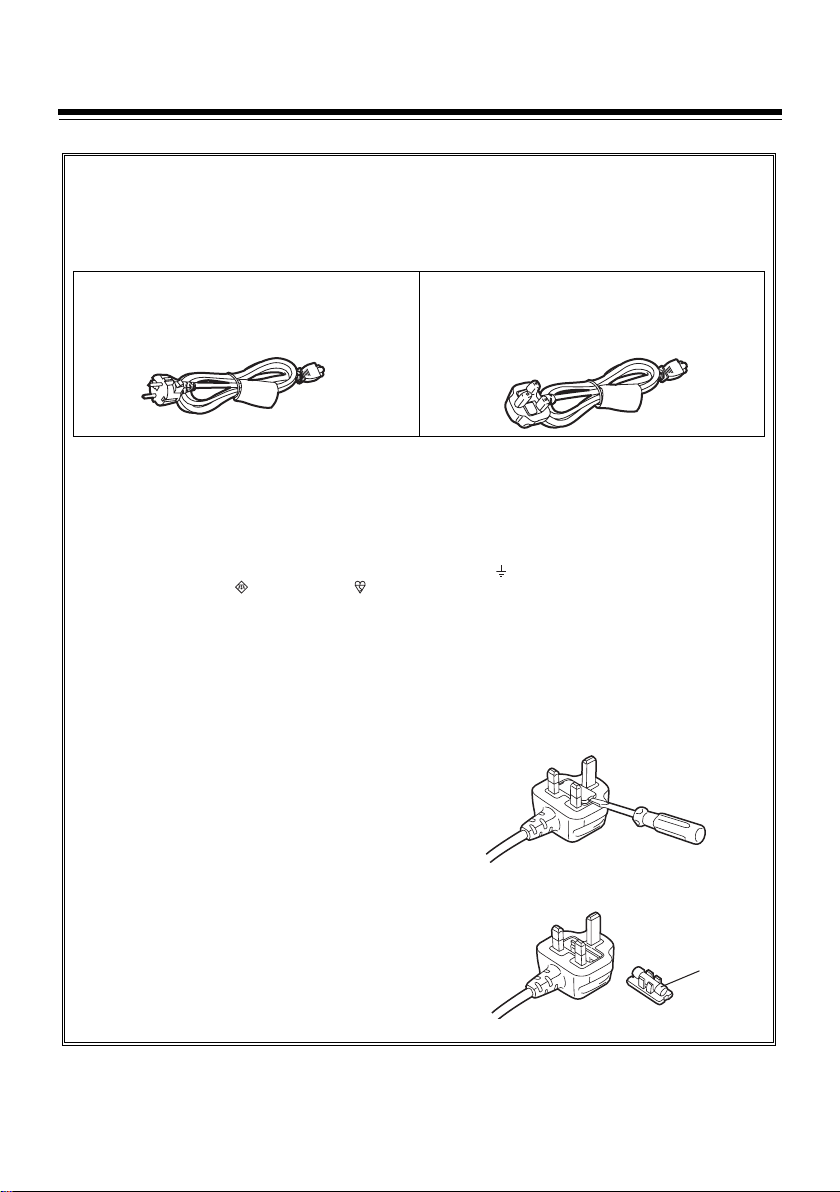
This product is equipped with 2 types of AC mains cable. One is for continental Europe, etc. and the other one
is only for U.K.
Appropriate mains cable must be used in each local area, since the other type of mains cable is not suitable.
FOR CONTINENTAL EUROPE, ETC.
Not to be used in the U.K.
FOR U.K. ONLY
This appliance is supplied with a moulded three pin
mains plug for your safety and convenience.
A 13 amp fuse is fitted in this plug.
Should the fuse need to be replaced please ensure that
the replacement fuse has a rating of 13 amps and that
it is approved by ASTA or BSI to BS1362.
Check for the ASTA mark or the BSI mark on the
body of the fuse.
If the plug contains a removable fuse cover you must
ensure that it is refitted when the fuse is replaced.
If you lose the fuse cover the plug must not be used until a replacement cover is obtained.
A replacement fuse cover can be purchased from your
local Panasonic Dealer.
IF THE FITTED MOULDED PLUG IS UNSUITABLE
FOR THE SOCKET OUTLET IN YOUR HOME THEN
THE FUSE SHOULD BE REMOVED AND THE PLUG
CUT OFF AND DISPOSED OF SAFELY. THERE IS A
DANGER OF SEVERE ELECTRICAL SHOCK IF THE
CUT OFF PLUG IS INSERTED INTO ANY 13 AMP
SOCKET.
If a new plug is to be fitted please observe the wiring
code as shown below.
If in any doubt please consult a qualified electrician.
WARNING: THIS APPLIANCE MUST BE
EARTHED.
IMPORTANT: The wires in this mains lead are co-
loured in accordance with the following code:
Green-and-Yellow:Earth
Blue: Neutral
Brown: Live
FOR U.K. ONLY
If the plug supplied is not suitable for your
socket outlet, it should be cut off and
appropriate one fitted.
As the colours of the wires in the mains lead of this appliance may not correspond with the coloured markings
identifying the terminals in your plug, proceed as follows:
z The wire which is coloured GREEN-AND-YELLOW
must be connected to the terminal in the plug
which is marked with the letter E or by the Earth
symbol or coloured GREEN or GREEN-ANDYELLOW.
z The wire which is coloured BLUE must be con-
nected to the terminal in the plug which is marked
with the letter N or coloured BLACK.
z The wire which is coloured BROWN must be con-
nected to the terminal in the plug which is marked
with the letter L or coloured RED.
How to replace the fuse
1. Open the fuse compartment with a screwdriver.
2. Replace the fuse.
Fuse
3
Page 4
CAUTION
RISK OF ELECTRIC SHOCK
DO NOT OPEN
CAUTION: TO REDUCE THE RISK OF ELECTRIC SHOCK,
DO NOT REMOVE COVER (OR BACK).
REFER TO SERVICING TO QUALIFIED SERVICE PERSONNEL.
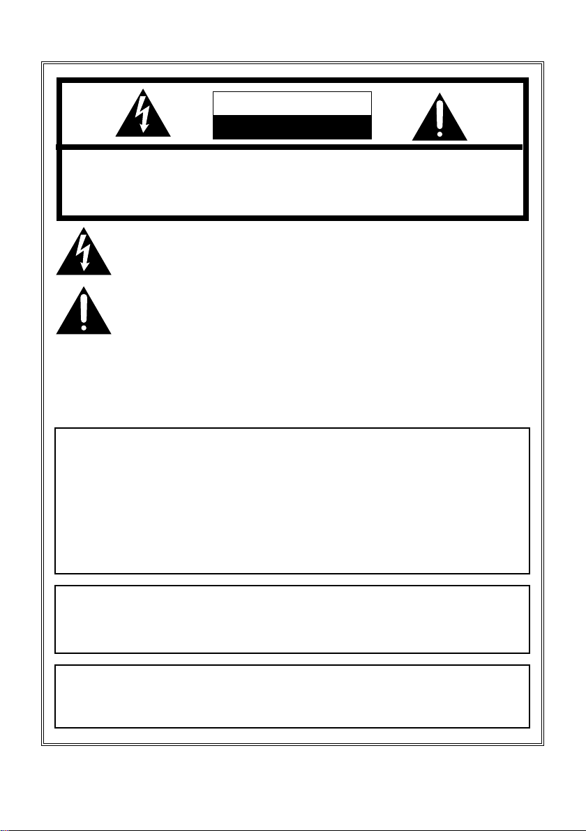
The lightning flash with arrowhead symbol, within an equilateral triangle, is intended
to alert the user to the presence of uninsulated “dangerous voltage” within the
product’s enclosure that may be of sufficient magnitude to constitute a risk of electric
shock to persons.
The exclamation point within an equilateral triangle is intended to alert the user to the
presence of important operating and maintenance (service) instructions in the
literature accompanying the appliance.
NO USER SERVICEABLE PARTS INSIDE.
DO NOT REMOVE COVER OF AC ADAPTER.
To reduce the risk of electric shock, do not remove cover. No user serviceable
parts inside.
Refer servicing to qualified service personnel.
WARNING:
z TO REDUCE THE RISK OF FIRE OR SHOCK HAZARD, DO NOT
EXPOSE THIS EQUIPMENT TO RAIN OR MOISTURE.
z TO REDUCE THE RISK OF FIRE OR SHOCK HAZARD, KEEP THIS
EQUIPMENT AWAY FROM ALL LIQUIDS-USE AND STORE ONLY IN
LOCATIONS WHICH ARE NOT EXPOSED TO THE RISK OF DRIPPING
OR SPLASHING LIQUIDS, AND DO NOT PLACE ANY LIQUID
CONTAINERS ON TOP OF THE EQUIPMENT.
CAUTION:
TO REDUCE THE RISK OF FIRE OR SHOCK HAZARD AND ANNOYING
INTERFERENCE, USE THE RECOMENNDED ACCESARRIES ONLY.
CAUTION:
THE AC OUTLET (MAINS SOCKET) SHALL BE INSTALLED NEAR THE
EQUIPMENT AND SHALL BE EASILY ACCESSIBLE.
4
Page 5

FCC NOTICE
Declaration of Conformity
Model Number: AJ-PCD10P
Trade Name: PANASONIC
Responsible Party: Matsushita Electric Corporation of America One Panasonic
Way, Secaucus, NJ 07094
Support contact: Panasonic Broadcast & Tlevision Systems Company
1-800-524-1448
This device complies with Part 15 of FCC Rules. Operation is subject to the following
two conditions:
(1) This device may not cause harmful interference, and (2) this device must accept
any interference received, including interference that may cause undesired operation.
To assure continued compliance, follow the attached installation instructions and do
not make any unauthorized modifications.
CAUTION:
This equipment has been tested and found to comply with the limits for a Class B
digital device, pursuant to Part 15 of the FCC Rules. These limits are designed to
provide reasonable protection against harmful interference in a residential
installation. This equipment generates, uses and can radiate radio frequency energy
and, if not installed and used in accordance with the instructions, may cause harmful
interference to radio communications. However, there is no guarantee that
interference will not occur in a particular installation. If this equipment does cause
harmful interference to radio or television reception, which can be determined by
turning the equipment off and on, the user is encouraged to try to correct the
interference by one of the following measures:
zReorient or relocate the receiving antenna.
zIncrease the separation between the equipment and receiver.
zConnect the equipment into an outlet on a circuit different from that to which the
receiver is connected.
zConsult the dealer or an experienced radio/TV technician for help.
The user may find the booklet “Something About Interference” available from FCC
local regional offices helpful.
FCC Warning: To assure continued FCC emission limit compliance, the user must
use only shielded interface cables when connecting to host computer or peripheral
devices. Also, any unauthorized changes or modifications to this equipment could
void the user’s authority to operate this device.
indicates safety information.
5
Page 6

Overview
The AJ-PCD10 (hereinafter referred to as “P2 drive”) is a data transfer device that uses a
USB 2.0 interface and is designed only for AJ-P2C series memory cards (hereinafter
referred to as “P2 card(s)”).
The P2 drive enables high-speed transfer to a personal computer of clip data shot with a P2
card camera-recorder.
This device supports not only the transferring and copying of clips recorded on P2 cards, but
also direct editing.
Features
z The P2 drive features five card slots.
z It enables high-speed data transfer using a USB 2.0 interface.
z It can be used as either an external or an internal drive.
Supplied Accessories
AC adapter
Mounting screws (8)
Rubber feet (4)
CD-ROM
(P2 driver, P2 card utility, install manual and operation manual)
Operation Manual (2)
(this manual and the Installation Manual)
Power cable for AC adapter
For U.S.
For continental
Europe,etc
6
For U.K.
Page 7

Parts and their Functions
Front Panel
(1) (2)
(1) Power Indicator
This indicator lights up in green when
the P2 drive is running.
(2) Status Indicator
This indicator lights up in green during
access to a P2 card.
<Note>
Removing a P2 card during access
may cause file corruption.
(3) Card Slots
The P2 drive’s card slots are designed
for P2 cards.
Proper operation cannot be
guaranteed when used with any card
other than P2 cards.
(4) EJECT Button
To remove a P2 card, press this button
so that the button pops out, then press
it in again.
<Note>
For Windows 2000 only : Open “My
Computer” and use the right button of
your mouse to select the drive from
which you want to remove a card, then
select “EJECT” before operating the
EJECT button.
(3) (4)
Rear Panel
DC IN 16V
USB 2.0
(1) (2) (3)(4)(5)
The picture shows the rear panel with its
cover removed.
(1) USB 2.0 connector (Type B)
This connects a USB cable.
Use a USB cable (shielded) compliant
with USB 2.0.
<Note>
The P2 drive supports USB 2.0 only. It
does not support personal computers
compliant with USB 1.1.
(2) DC IN 16V Socket
For external use of the P2 drive,
connect an AC adapter to this socket.
(3) DC IN 12V Socket
To use the P2 drive mounted in a
personal computer, connect one of the
power supply connectors inside the
personal computer to this socket.
<Note>
Do NOT supply power to both the DC
IN 12V socket and DC IN 16V socket
at the same time.
(4) Cable Clamp
Use this clamp to secure the AC
adapter cable when connecting the P2
drive to a personal computer for
external use of the Drive.
(5) Antitheft Lock
A commercially available antitheft
cable can be connected to this lock.
DC IN 12V
7
Page 8

Inserting a P2 Card
When inserting a P2 card into the slot in the
P2 drive, make sure you keep the card
horizontal as you ease it in.
Forcing the card in on an angle may cause
a problem.
Write-protection of P2 Card
A P2 card has a write-protect switch.
Setting this switch to “PROTECT” can
prevent writing and deleting of data.
Note: The write-protect switch is not
effective when the P2 card is inserted in the
P2 drive. Make sure you remove the P2
card from the P2 drive, set the switch, then
re-insert the card, in order to effect the
switch setting.
PROTECT
Setting the writeprotect switch to
“PROTECT” can
prevent writing and
deleting of data.
Setting the writeprotect switch to
this side allows
writing and
deleting of data.
Installation
There are two ways to connect the P2 drive to a personal computer :
1. Using the P2 drive as an external drive connected to a personal computer
2. Mounting the P2 drive in a 5-inch bay of a desktop personal computer
<Notes>
z Connect the P2 drive to a personal computer before installing the P2 driver to the
computer from the installation CD.
For details, refer to the Installation Manual.
z The P2 drive is designed for a 5-inch bay. If all file bays are occupied, you will need to
remove one of the built-in drives to make room for the P2 drive.
z The P2 drive should be used in a personal computer whose design allows the front panel
of the drive to be manipulated.
8
Page 9

To Connect the P2 drive to a Personal Computer for External
Use
1 Attach the rubber feet to the dimples
on the base of the P2 drive.
Dimples
2 Start the personal computer.
3 Plug the AC adapter supplied with the
P2 drive into the DC IN 16 socket on
the P2 drive.
The P2 drive will start.
DC IN 16V
USB 2.0
DC IN 12V
4 Plug a USB 2.0 cable B connector into
the USB connector on the P2 drive.
<Note>
No USB 2.0 cable is supplied with the P2
drive in the package. Use a commercially
available USB 2.0 cable (shielded).
Take care to use a USB cable that is no
longer than 3 metres. The P2 drive may not
operate properly with a cable longer than 3
metres.
5 Plug the other end (A connector) of
the USB 2.0 cable into the USB 2.0
port on the personal computer.
6 Verify that the personal computer
recognises the P2 drive.
<Notes>
z In Windows XP, some card slots of the P2
drive may be assigned drive names that
have already been assigned to existing
networks. Reassign network drive names
if your personal computer does not
display all five card slots.
z To disconnect the USB cable, select
“Safety Remove Hardware” from the
system tray on the taskbar, de-activate
[Panasonic P2 Series USB Device], then
unplug the cable.
USB 2.0
USB 2.0 connector
DC IN 16V
DC IN 12V
9
Page 10

To Mount the P2 drive in a Personal Computer 5-inch Bay
1 Turn OFF the personal computer’s
power.
2 Undo the six screws and remove the
cover.
DC IN 16V
USB 2.0
DC IN 12V
3 Mount the P2 drive in a 5-inch bay on
the personal computer. Use the
screws supplied with the P2 drive for
mounting.
Please refer to your computer’s
instruction manual for guidance in
mounting to 5-inch bay drives.
Screws
4 Plug the USB 2.0 cable B connector
into the USB 2.0 connector on the P2
drive, then plug the A connector into
the USB 2.0 port on the motherboard
of the personal computer.
DC IN 16V
USB 2.0
USB 2.0 connector
DC IN 12V
<Note>
USB 2.0 connector pinouts vary according
to the type of motherboard type. Check
your computerís instruction manual before
purchasing a commercially available USB
2.0 cable (shielded).
5 Connect the P2 drive to the internal
power cable (4 pins) of the personal
computer.
DC IN 16V
USB 2.0
Power cable
DC IN 12V
6 Start the personal computer and verify
that it recognises the P2 drive.
<Notes>
z The P2 drive may not be able to be
fastened securely in some types of
personal computers.
z If all 5-inch bays are occupied, you will
need to remove one of the built-in drives
to make room for the P2 drive.
z The P2 drive should be used in a
personal computer whose design allows
the front panel of the Drive to be
manipulated.
z In Windows XP, some card slots of the P2
drive may be assigned drive names that
have already been assigned to existing
networks. Reassign network drive names
if your personal computer does not
display all five card slots.
10
Page 11

Specifications
AC 100 V - 240 V, 0.8 A - 0.4 A, 50 - 60 Hz
(AC adapter input)
DC 16 V, 0.8 A
(when used with AC adapter)
DC 12 V, 1.0 A
(when mounted in a personal computer)
indicates safety items.
External dimensions (W a H a D)
5-7/8 a 1-11/16 a 7-7/8 inches
(148.4 a 42.5 a 199.0 mm)
(excluding protruding parts)
Weight
Approximately 2.64 lbs
(approx. 1.2 kg)
[Environmental
conditions]
Operating temperature
32 °F to +104 °F (0 °C to +40 °C)
Operating humidity
0% to 90% (w/o condensation)
[Card slots]
PC card Type II a 5
(CardBus compliant)
Please note that specifications and
appearance are subject to change, for
improvement purpose, without notice.
[Personal Computer
System Requirements]
OS (proper operation guaranteed)
Windows XP Professional
(SP1 or later)
Windows 2000 (SP4 or later)
Main Memory
512 MB or greater recommended
Interface
USB Ver. 2.0 compliant
11
Page 12

PANASONIC BROADCAST & TELEVISION SYSTEMS COMPANY
UNIT COMPANY OF MATSUSHITA ELECTRIC CORPORATION OF AMERICA
Executive Office:
One Panasonic Way 4E-7, Secaucus, NJ 07094 (201) 348-7000
EASTERN ZONE:
One Panasonic Way 4E-7, Secaucus, NJ 07094 (201) 348-7621
Southeast Region:
1225 Northbrook Parkway, Ste 1-160, Suwanee, GA 30024 (770) 338-6835
Central Region:
1707 N Randall Road E1-C-1, Elgin, IL 60123 (847) 468-5200
WESTERN ZONE:
3330 Cahuenga Blvd W., Los Angeles, CA 90068 (323) 436-3500
Government Marketing Depar tment:
52 West Gude Drive, Rockville, MD 20850 (301) 738-3840
Broadcast PARTS INFORMATION & ORDERING:
9:00 a.m. – 5:00 p.m. (EST) (800) 334-4881/24 Hr. Fax (800) 334-4880
Emergency after hour parts orders (800) 334-4881
TECHNICAL SUPPORT:
Emergency 24 Hour Service (800) 222-0741
Panasonic Canada Inc.
5770 Ambler Drive, Mississauga, Ontario L4W 2T3 (905) 624-5010
Panasonic de Mexico S.A. de C.V.
Av angel Urraza Num. 1209 Col. de Valle 03100 Mexico, D.F. (52) 1 951 2127
Panasonic Sales Company
Division of Matsushita Electric of Puerto Rico Inc.
San Gabriel Industrial Park, 65th Infantry Ave., Km. 9.5, Carolina, Puerto Rico 00630 (787) 750-4300
Panasonic Broadcast Europe
Panasonic Marketing Europe GmbH
Hagenauer Str. 43, 65203 Wiesbaden-Biebrich Deutschland Tel: 49-611-235-481
VQT0L23 (E) F0604T0
 Loading...