


Operating
Instructions
INTRODUCTION
CONTROLS AND
CONNECTORS
Model AG-
Professional/Industrial video
P
CONNECTIONS
ON-SCREEN/MENU
SWITCHES
PREPARATION
RECORDING
PLAYBACK AND
SPECIAL-EFFECTS
PLAYBACK
Printed in Japan
VQT9726
Time Lapse Video Cassette Recorder
Before attempting to connect, operate or adjust this product, please read these instructions completely.
LLT0004-001A
TROUBLE-
APPENDIXES
P
SHOOTING
SAFETY PRECAUTIONS
CAUTION ATTENTION
RISK OF ELECTRIC SHOCK
DO NOT OPEN
CAUTION: TO REDUCE THE RISK OF ELECTRIC SHOCK,
WARNING:
TO REDUCE THE RISK OF FIRE OR ELECTRIC
SHOCK, DO NOT EXPOSE THIS APPLIANCE
TO RAIN OR MOISTURE.
This unit should be used with 120 V AC only.
CAUTION:
To prevent electric shocks and fire hazards, DO NOT
use any other power source.
NOTE:
The rating plate (serial number plate) is on the rear of the unit.
INFORMATION
This equipment has been tested and found to comply with the
limits for a Class B digital device, pursuant to Part 15 of the
FCC Rules. These limits are designed to provide reasonable
protection against harmful interference in a residential
installation. This equipment generates, uses, and can radiate
radio frequency energy and, if not installed and used in
accordance with the instructions, may cause harmful interference to radio communications. However, there is no guarantee that interference will not occur in a particular installation.
If this equipment does cause harmful interference to radio or
television reception, which can be determined by turning the
equipment off and on, the user is encouraged to try to correct
the interference by one or more of the following measures:
● Reorient or relocate the receiving antenna.
● Increase the separation between the equipment and
receiver.
● Connect the equipment into an outlet on a circuit different
from that to which the receiver is connected.
● Consult the dealer or an experienced radio/TV technician for
help.
CAUTION
To assure continued compliance follow the attached
installation instructions and do not make any unauthorized
modificaitons.
DO NOT REMOVE COVER (OR BACK).
NO USER-SERVICEABLE PARTS INSIDE.
REFER SERVICING TO QUALIFIED SERVICE PERSONNEL
The lightning flash with arrowhead symbol, within an
equilateral triangle, is intended to alert the user to the
presence of uninsulated “dangerous voltage” within
the product’s enclosure that may be of sufficient
magnitude to constitute a risk of electric shock to
persons.
The exclamation point within an equilateral triangle is
intended to alert the user to the presence of important
operating and maintenance (servicing) instructions in
the literature accompanying the appliance.
RISQUE D’ELECTROCUTION
NE PAS OUVRIR
ATTENTION: POUR EVITER TOUT RISQUE D’ELECTROCUTION
SE REFERER A UN AGENT QUALIFIE EN CAS DE PROBLEME.
NE PAS OUVRIR LE BOITER.
AUCUNE PIECE INTERIEURE N’EST
A REGLER PAR L’UTILISATEUR.
Le symbole de l’éclair à l’intérieur d’un triangle
équilatéral est destiné à alerter l’utilisateur sur la
présence d’une “tension dangereuse” non isolée
dans le boîtier du produit. Cette tension est suffisante
pour provoquer l’électrocution de personnes.
Le point d’exclamation à l’intérieur d’un triangle
équilatéral est destiné à alerter l’utilisateur sur la
présence d’opérations d’entretien importantes au
sujet desquelles des renseignements se trouvent
dans le manuel d’instructions.
*Ces symboles ne sont utilisés qu’aux Etats-Unis.
AVERTISSEMENT:
POUR EVITER LES RISQUES D’INCENDIE OU
D’ELECTROCUTION, NE PAS EXPOSER
L’APPAREIL A L’HUMIDITE OU A LA PLUIE.
Ce magnétoscope ne doit être utilisé que sur du
courant alternatif en 120 V.
ATTENTION:
Afin d’éviter tout resque d’incendie ou
d’électrocution, ne pas utiliser d’autres sources
d’alimentation électrique.
REMARQUE:
La plaque d’identification (numéro de série) se trouve sur le
panneau arrière de l’appareil.
WARNING:
The battery used in the AG-TL950P must be replaced by a
PANASONIC authorized service dealer only.
AVERTISSEMENT:
La pile utilisée dans l’AG-TL950P ne devra être remplacée
que par un service après-vente PANASONIC agréé.
CAUTION:
Do not install or place this unit in a bookcase, built-in cabinet
or in another confined space in order to keep well ventilation
condition. Ensure that curtains and any other materials do not
obstruct the ventilation condition to prevent risk of electric
shock or fire hazard due to overheating.
ATTENTION:
Ne pas installer cet appareil dans une bibliothèque, un meuble
fermé ou autres endroits renfermés. Installer l’appareil dans
un endroit bien ventilé. S’assurer qu’aucun rideau ou autre
matériel ne bouche la ventilation du lecteur de cassetie vidéo
afin de prévenir tout risque de chocs électriques ou de
dangers d’incendie dû au surchauffement.
THIS CLASS B DIGITAL APPARATUS COMPLIES WITH
CANADIAN ICES-003.
CET APPAREIL NUMÉRIQUE DE LA CLASSE B EST
CONFORME À LA NORME NMB-003 DU CANADA.
2
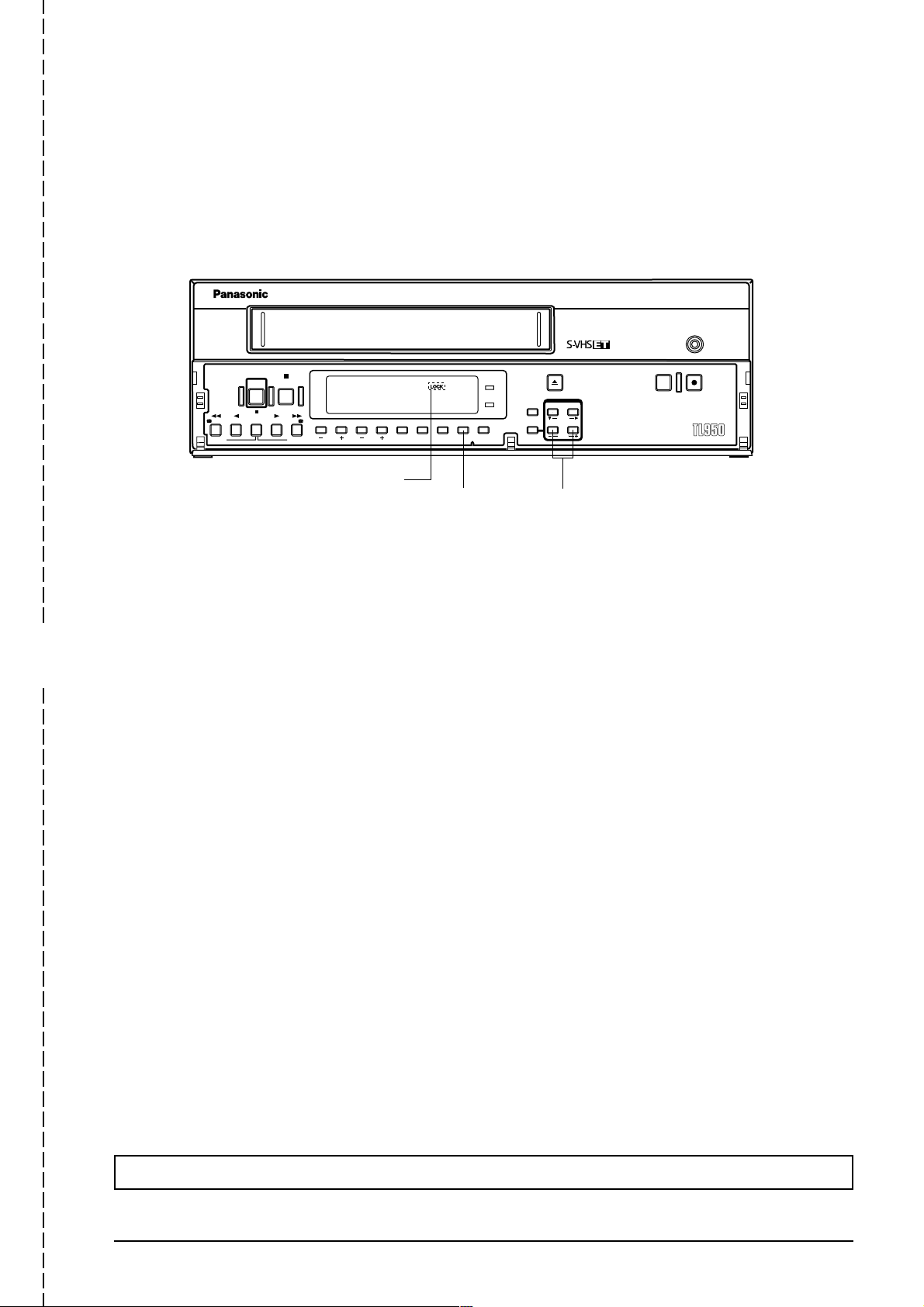
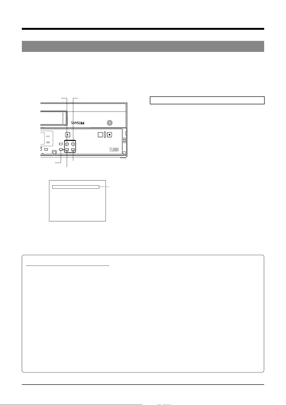
OPERATION LOCK
By engaging the operation lock system [LOCK], you can prevent accidental or deliberate interference with recording
operation or power supply.
When this function is activated, all operation buttons are disabled.
REC
STOP
POWER
PAUSE/
/REW
REV ADV FWD ADV
REV PLAY
STILL
PLAY FF/
“LOCK” indicator
TRACKING
V. LOCK
SEARCH COUNTER
TIMER
[LOCK] button
LOCK CNT RESET
POWER
HDR
EJECT
/
RESET
CANCEL
ON SCREEN
SHIFT
MENU TIMEMODE
SET
[TIME MODE+/–] button
REC REVIEW REC
-
AG
”
1 Engage the mode you want to lock (such as the Rec or Play mode).
2 While pressing the [LOCK] button, press the [TIME MODE+/–] button. “LOCK” is shown on the display, indicating
that the Operation Lock mode is engaged.
3 To unlock the VCR, press the [TIME MODE+/–] button while pressing the [LOCK] button. The “LOCK” indication on
the display disappears and the unit can now be operated normally.
To prevent unauthorized use, detach this page and keep it in a safe place.
3

4

CONTENTS
1 INTRODUCTION
1-1 Major Features............................................. 6
1-2 Periodical Maintenance................................ 7
1-3 Precautions.................................................. 7
1-4 Daily Inspection............................................ 8
1-5 Regarding S-VHS ET Rcording ................... 8
2 CONTROLS AND CONNECTORS
2-1 Front Panel .................................................. 9
2-2 Display ....................................................... 11
2-3 Rear Panel................................................. 12
3 CONNECTIONS
3-1 Connecting to a Camera............................ 14
3-2 System Using Sequential Switcher............ 15
3-3 Connecting the Rear Panel Input/Output
Terminal Connections................................ 16
4 ON-SCREEN/MENU SWITCHES
4-1 On-Screen Display..................................... 17
4-2 Main Menu Display .................................... 18
4-3 Date and Time Setting ............................... 19
4-4 Hour Meter Display .................................... 20
4-5 Alarm Input/Power Loss Data Display ....... 21
4-6 Menu Switch Setting .................................. 22
4-7 Contents of Menu Switches ....................... 23
7 PLAYBACK AND SPECIAL-EFFECTS
PLAYBACK
7-1 Preparation ................................................ 46
7-2 Playback .................................................... 46
7-3 Special-Effects Playback ........................... 47
• Still/Field Advance/Reverse Playback .... 47
• Shuttle Search ........................................ 48
7-4 Alarm Search/Date and Time Search ........ 49
7-5 Repeat Playback........................................ 51
7-6 Counter Memory Function ......................... 51
7-7 Tracking/V. Lock Adjustment ..................... 52
7-8 QUASI-V .................................................... 52
8 TROUBLESHOOTING
8-1 Error Indications......................................... 53
8-2 No Error Indication..................................... 54
9 APPENDIXES
9-1 Tape Reel Counter/Tape Remaining Time
Table.......................................................... 55
9-2 Rear Panel’s Inputs/Outputs ...................... 56
9-3 Specifications............................................. 57
5 PREPARATION
5-1 Cassette Loading/Unloading...................... 27
5-2 Recording/Playback Speed Mode
Selection .................................................... 28
6 RECORDING
6-1 Switch Setting During Recording ............... 29
6-2 Recording Basic Operation........................ 30
6-3 Timer Recording ........................................ 31
• Timer Recording Program Setting .......... 31
• Holiday Timer Recording Setting ............ 35
• Canceling/Changing Timer Recording
Program .................................................. 36
• Notes on Timer Recording...................... 37
6-4 Alarm Recording ........................................ 38
6-5 Sensor Recording ...................................... 40
6-6 Series Recording ....................................... 41
6-7 Repeat Recording ...................................... 43
6-8 Recording with External VCR Activation
Signal......................................................... 44
6-9 How to Restore Recording After Power
Failure........................................................ 45
6-10 External Timer Recording .......................... 45
6-11 Tape End Buzzer ....................................... 45
The AG-TL950P is a video cassette recorder able to
execute timelapse recording with VHS cassettes.
Use only video cassettes bearing the
This unit is designed for professional use.
Panasonic is not liable for compensation for loss or
damage to recordings in the event this unit fails to
record or play back properly because the unit
malfunctions or a defective video cassette tape is used.
Please note that it may be unlawful to use any material
recorded from TV broadcast programs or pre-recorded
programs without the consent of the owner of
copyright, except in cases where this material is
recorded exclusively for personal use.
or mark.
5

1 INTRODUCTION
1-1 Major Features
5 S-VHS/S-VHS ET recording
S-VHS or S-VHS ET is employed as the recording
mode. Employing the S-VHS ET recording mode
enables recording with a horizontal resolution of 400
lines on a VHS cassette. The VHS mode is only
available for playback.
5 Extended timelapse recording for up to 960 hours
Recording times are selectable from 2 hours (SP mode),
6 hours (EP mode) and L12/L18/L24/24/48/72/120/168/
240/480/960 (Timelapse mode) (when T-120 tape is
used).
5 High-resolution recording
Delivers horizontal resolution of more than 400 lines
even in color mode.
*When a tape recorded on this unit is played back on
another VCR, noise may appear on playback picture.
5 High-density recording (HDR) function
Using the EP head, the tape is advanced at a fine pitch
for timelapse recording. In this way, about three times
more information is recorded in the same period than in
conventional timelapse modes. While this results in
some degradation of picture quality, the increased
coverage allows you to analyze the development of a
situation in greater detail. The actual recording duration
on the tape is the same as that of an ordinary timelapse
recording (select with menu switch <HIGH DENSITY
REC>).
5 Alarm recording function
When an alarm signal is input in the Record mode, the
2/6/L12/L18/L24/24/48-hour mode is automatically
engaged. Alarm recording time can be selected from 5,
10, 15, 30, 60, 120, or 180 sec., to COUNTINUE, or set
manually.
An index code is automatically recorded at the start
point of the alarm recording for use as an alarm cue
signal. Alarm recording points can be accessed quickly
with the alarm search function.
5 Sensor recording
Whenever an alarm signal is input in the Stop mode
(Stop, Timer Recording Standby or Operating Off
mode), the Record mode is automatically engaged.
5 Time/date generator
Superimposes date, month, year, hour, minute and
second on the image during recording. Also allows you
to display the number of alarms, alarm time, and the
number of the power failures on a monitor.
5 Timer-recording function
Up to 8 programs can be set for daily, weekly, or
weekday timer-recording. You can also set timer
recording for up to 16 days a year by specifying the date
(holidays, for example).
5 Tape position search function
You can automatically search the start of an alarm
recording or search for a recording made at a specified
date and time.
5 Recording check function
Recording conditions (quality) can be checked at any
time during recording by pressing the REC REVIEW
button.
5 Operation lock system
The secret operation lock system prevents an accidental
or deliberate interference with VCR operation.
5 Camera switching signal output terminal
5 Warning function
Error indications are shown on the front panel display.
Error warnings include condensation and problems with
cassette loading, cassette unloading, or the rotating
system operation mode.
5 Operating mode-off video throughout function
Even when the operating mode is off, the camera’s EE
input can be output from the VCR.
5 Series recording function
Two or more AG-TL950P can be connected for
extended, long-term series recording. As the tape in
each VCR reaches the end, the next unit in the series
will automatically start recording.
5 Time adjust function
With the IN/OUT terminal for time adjustment, the time
difference can be set to “0” with m u l t ip l e AG-TL950P
connected. (adjustment time: 00:00/12:00)
5 Digital hour meter display
5 Repeat playback/recording
5 Alarm recording, tape end and warning electronic
buzzer
5 Recording control with external activation signal
5 Counter end function
5 External timer connection
5 Summer time compensation function
6
1 INTRODUCTION
1-2 Periodical Maintenance
This VCR incorporates precision mechanical parts which will collect dirt over time and ultimately deteriorate and wear out.
Over long periods of use, dirt and dust accumulates on the heads, drums and tape transport mechanisms. Dust which
penetrates the VCR (especially during outdoor use) also promotes the wear and deterioration of mechanical parts by causing
poor contact between tape and heads. This also prevents the VCR from maintaining video and audio quality at high levels.
To prevent wear and deterioration, clean the heads regularly using a head cleaning tape. However, because a head cleaning
tape alone cannot clean the entire tape transport mechanism, this should also be inspected periodically to prevent any
problems that could result from a sudden failure.
As replacement and adjustment of parts require advanced skills and specialized equipment, please contact the person in
charge of professional video equipment at your nearest Panasonic-authorized service agent for servicing.
Monitoring Usage Time
The total operation time reached by an ordinary home VCR
in 5 or 6 years may be reached by a professional VCR in
as few as 5 or 6 months. Therefore, it is important that the
total hours of operation be carefully monitored. An hour
meter in the on-screen display (see page 20) shows the
accumulated time. In the chart below, the hours
accumulated in each month are shown in relation to the
number of hours used per day. Times shown in the shaded
area indicate that maintenance should be performed.
Usage
time per
day
1 month 2 months 3 months 6 months 12 months
2 hours 60 120 180 360 720
8 hours 240 480 720 1440 2880
12 hours 360 720 1080 2160 4320
24 hours 720 1440 2160 4320 8640
1-3 Precautions
Handling and storage place
5 Avoid using the unit in places subject to the following
conditions:
• extreme heat or cold
• strong magnetic fields (do not use a transceiver within 2
meters of this unit)
• high humidity
• dust and soil
• vibrations
• variations in temperature
5 Use this unit in horizontal (flat position) only.
5 To avoid overheating the unit, do not block ventilation
slots or stack the units. If the internal temperature rises
too high, the tape may be damaged.
5 When playing back a tape recorded on another VTR, there
may be some noise output even when tracking
adjustments are carried out. This is not a malfunction.
5 Do not leave the unit in the Still or Record Pause mode for a
long time as this may damage the tape.
Condensation
Periodic Maintenance
Check or replace the following mechanical parts according
to the running time.
Running time 1000H 2000H 3000H 4000H
Drum ass’y (including heads) ^ 䡬䡬䢇
Pinch rollers ^ 䡬䡬䢇
Drive parts ^^ ^ 䡬
^ : Cleaning
䡬 : Check or replace as required.
䢇 : Replace
• Maintenance requirements may vary depending on the
operating environment and usage. The information
above should be used as a reference guide.
Replace the built-in lithium battery approximately every
two years.
After about 3 minutes, this unit automatically enters the Stop
mode.
5 Handle the unit carefully
• Do not place anything heavy on the unit (a monitor, etc.). A
malfunction may occur.
• Do not put any foreign substance into the cassette loading
slot.
• Avoid violent shocks to the recording chassis during
transportation. Remove the cassette tape from the unit for
transportation.
5 Turn off the power to save electricity when not using the
unit.
5 To clean the unit, just wipe it with a soft cloth.
Use of thinner or benzene may dissolve or tarnish the surface.
To remove stains, wipe it using a cloth dipped in water mixed
with a little amount of neutral detergent, and wipe it again with
a dry cloth later on.
5 Never put your hand into the front-loading tape door.
If you do so, you may get hurt.
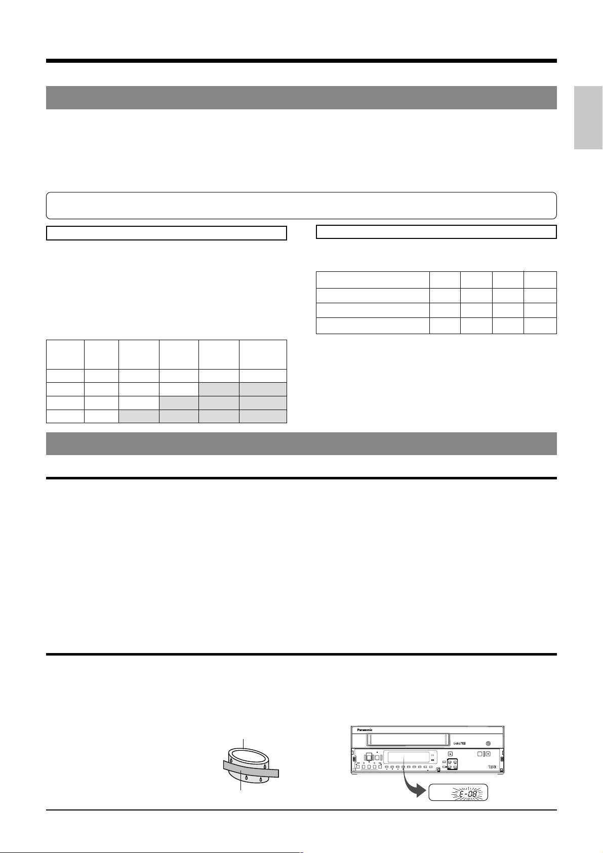
5 Condensation
When cold beer is poured into a glass, water drops
appear on the glass’s surface. This phenomenon is
called “condensation”. When condensation occurs on
the VCR’s head drum and tape guides it may damage
the tape.
5 Condensation occurs in the
following cases:
Head drum
• When the VCR is moved from a
cold place to a warm place.
• In a room that has just been heated
or in an area directly exposed to a
cooler.
• When there is excessive humidity.
Video tape
5 When condensation is expected to occur
Turn the power of the VCR on before use.
5 If condensation has occurred
The VCR automatically ejects the cassette and the error
indication “E-08” blinks on the display. Operation is
disabled until the “E-08” indication on the display goes out.
REC
STOP
POWER
PAUSE/
/REW
PLAY FF/
REV PLAY
STILL
REV ADV FWD ADV
TIMER
V. LOCK
TRACKING
SEARCH COUNTER
LOCK CNT RESET
EJECT
POWER
HDR
RESET
CANCEL
MENU TIMEMODE
REC REVIEW REC
/
ONSCREEN
SHIFT
SET
AG-
7
1 INTRODUCTION
1-3 Precautions
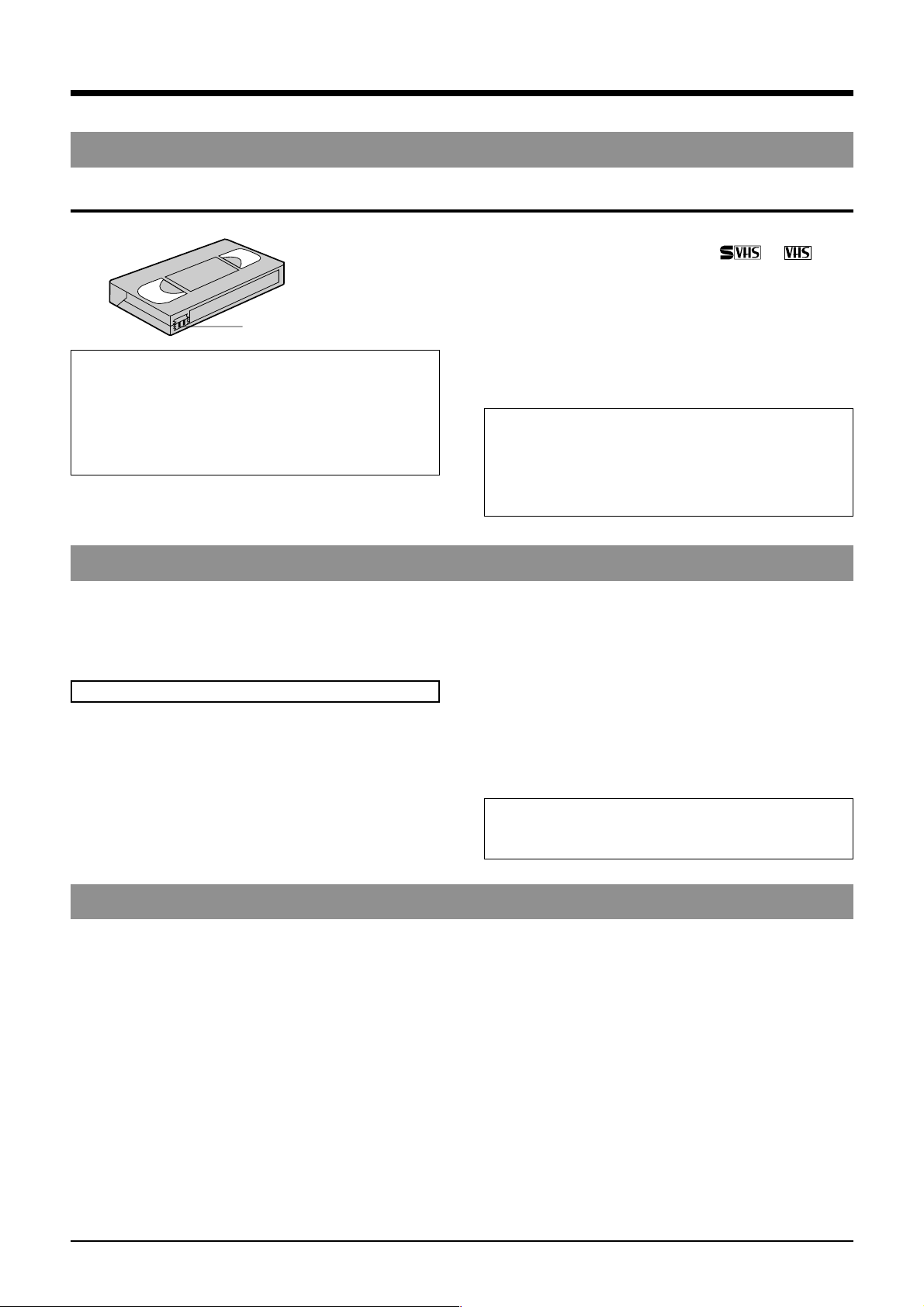
Video cassette
Erasure prevention tab
Timelapse recording (24H-960H mode) is
performed over very long periods of time
which means that a durable tape is required.
When using VHS tapes, do not use tapes with
recording times of more than 120 minutes
(T-160/T-180 etc.).
For best results, use a T-120 tape.
• Only use video cassette bearing the or mark.
• To prevent accidental erasure of a recorded tape, break
the erasure prevention tab on the cassette. To use a
cassette with a broken tab, place a piece of cellophane
tape over the broken tab.
• Video cassettes cannot be used upside down.
• Leaving the tape in a partially wound condition for a long
time may damage the tape. Rewind the tape to the
beginning before storage.
To obtain the best picture quality, use an HG (high
grade) tape . Degradation of picture quality may
result with some types of tape. Make a test recording
before performing any important recording to check
the picture quality.
1-4 Daily Inspection
Although this unit has been designed for reliable operation
over a long period of time, a daily inspection is
recommended to ensure optimum performance. In
particular, be sure to check the repeat recording/playback
function on a daily basis.
Inspection procedure
1 Turn on the power for all units connected to the
surveillance system.
2 Check the quality of the image shown on the monitor.
1-5 Regarding S-VHS ET Recording
• The S-VHS ET recording feature of this unit ensures a
picture quality (horizontal resolution of 400 lines) on a par
with S-VHS when a VHS tape is used. This function is
automatically activated when a VHS tape is inserted into
the unit and recording started. This unit does not perform
normal VHS recording.
• S-VHS ET recording is not performed in the linear
slow (L12/L18/L24) mode.
• Playback of a tape recorded in the S-VHS ET format
should be performed on this unit, or on a video deck
equipped with function for S-VHS or S-VHS simple
playback (SQPB). (Playback may not be possible on
some video decks.)
• HG (high-grade) VHS tapes are recommended for S-VHS
ET recording. Depending on the characteristics of the
tape, correct recording may not always be possible. Use
the tape after making a test recording to ensure that
recording is conducted correctly.
3 Check that the date and time shown on the monitor are
correct.
4 Rewind the tape recorded the previous day for several
seconds.
5 Press the play button for playback.
6 Check that the playback picture is normal.
7 Check that the recorded date and time are correct.
5 This unit includes a Recording Check function (using the
[REC REVIEW] button). Use these features to quickly
check recording quality on a daily basis.
If any problems are found after inspection, turn the
power off, unplug the mains plug from the socket, and
contact your Panasonic dealer.
• Accidentally inserting a tape recorded in the S-VHS ET
format into a dedicated VHS deck that is not designed for
playback of this type could result in damage. To avoid this
kind of accident, mark cassettes labels in such a way that
you can easily distinguish between S-VHS ET and VHS
recordings when storing cassettes.
• As far as possible avoid operations that apply a load to
the tape, such as search playback, etc. This will result in
deteriorating picture quality.
• Noise may appear in the playback picture during search
playback and field advance. This is not a malfunction.
8
2 CONTROLS AND CONNECTORS
2-1 Front Panel
STOP
POWER
PAUSE/
/REW
REV PLAY
REV ADV FWD ADV
STILL
PLAY FF/
TRACKING
V. LOCK
TIMER
9 8
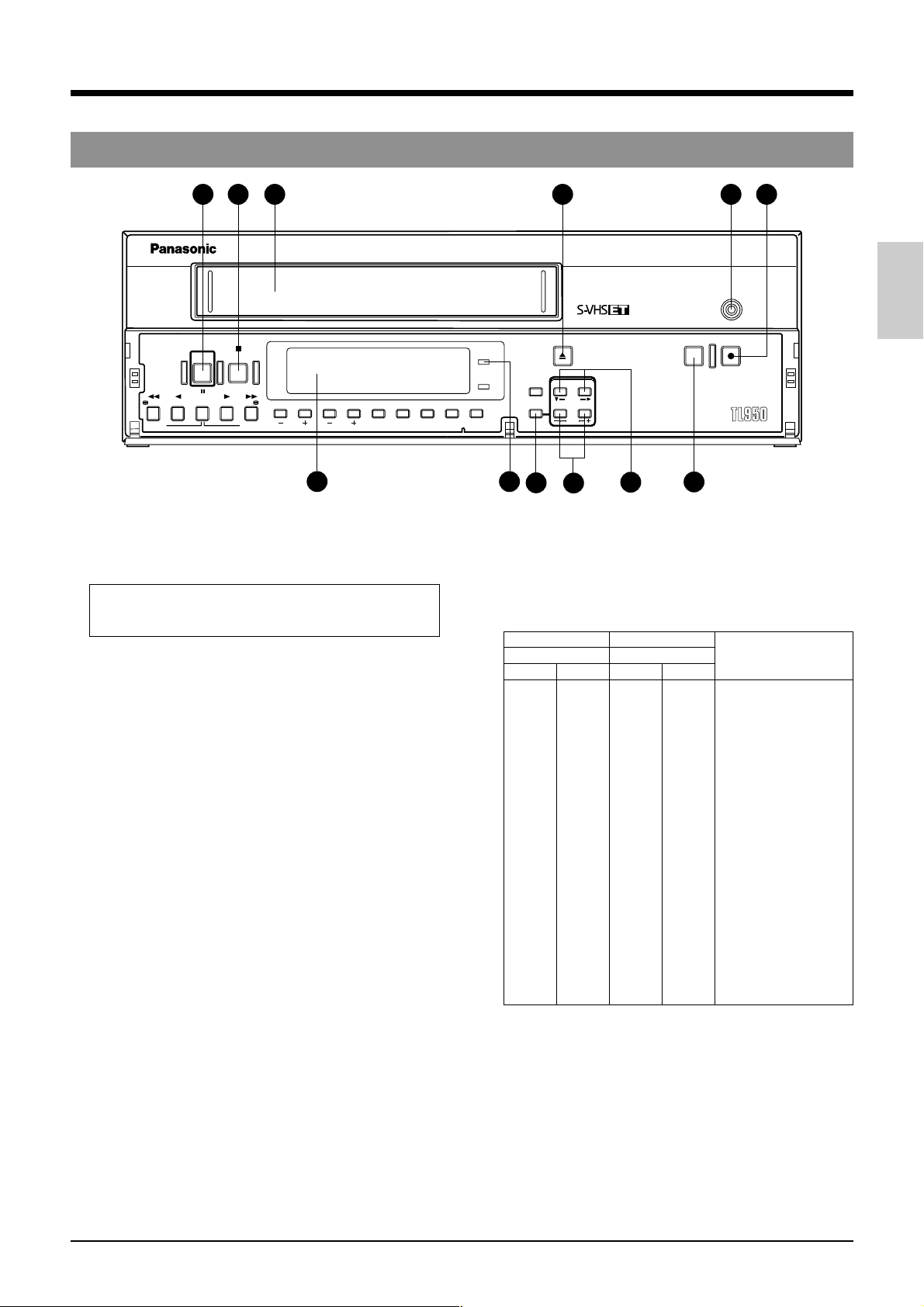
1 [POWER] power on/off button
Press to turn the operating mode ON/OFF. When this
button is POWER indicator 8 lights and the unit can be
operated. When a cassette is loaded, operating mode is
switched on and the POWER indicator lights automatically.
The POWER button does not completely shut off the
mains power to the unit, but switches the operating current
on and off.
2 [STOP] button
Press this button to stop the tape.
3 Cassette loading slot
Insert a cassette in this slot. Use a VHS cassette tape.
4 [EJECT] button
Press to eject the cassette.
5 [REC] indicator
This indicator lights during recording if menu switch <REC
TALLY> on the <F. DISP> screen is set to “ON”.
6 [REC] button
Press this button in the Stop mode to engage the Record mode.
Press to engage the Record mode in the Rec-Pause mode.
7 [REC REVIEW] button
Use this button to check recording.
When pressed in the Record mode, the VCR will rewind the
tape for about 5 seconds of tape time and then play back
the rewound section in the 2H/6H mode to check recording
quality. Recording is resumed automatically after playback
at the point where recording was interrupted.
• If picture quality is judged to be inferior during recording
check, the heads are cleaned automatically and the error
code “E-09” is shown on the display for about 10 seconds.
Recording will continue regardless of the results of the
recording check.
8 [POWER] indicator
Lights when the
9 Display section
For details, refer to page 11.
0 [ON SCREEN/SHIFT 7/t] buttons
• Use these buttons on the normal screen to move the
display position or recording position of on-screen
information. The position can be moved down by pressing
the 7 button and to the right by pressing the t button.
• Use these buttons on the menu screen to select the desired
item in date/time setting, timer program setting and menu
switch setting.
1 [POWER] button is turned on.
SEARCH COUNTER
4
POWER
LOCK CNT RESET
EJECT
/
HDR
RESET
CANCEL
ON SCREEN
SHIFT
MENU TIME MODE
SET
12
11
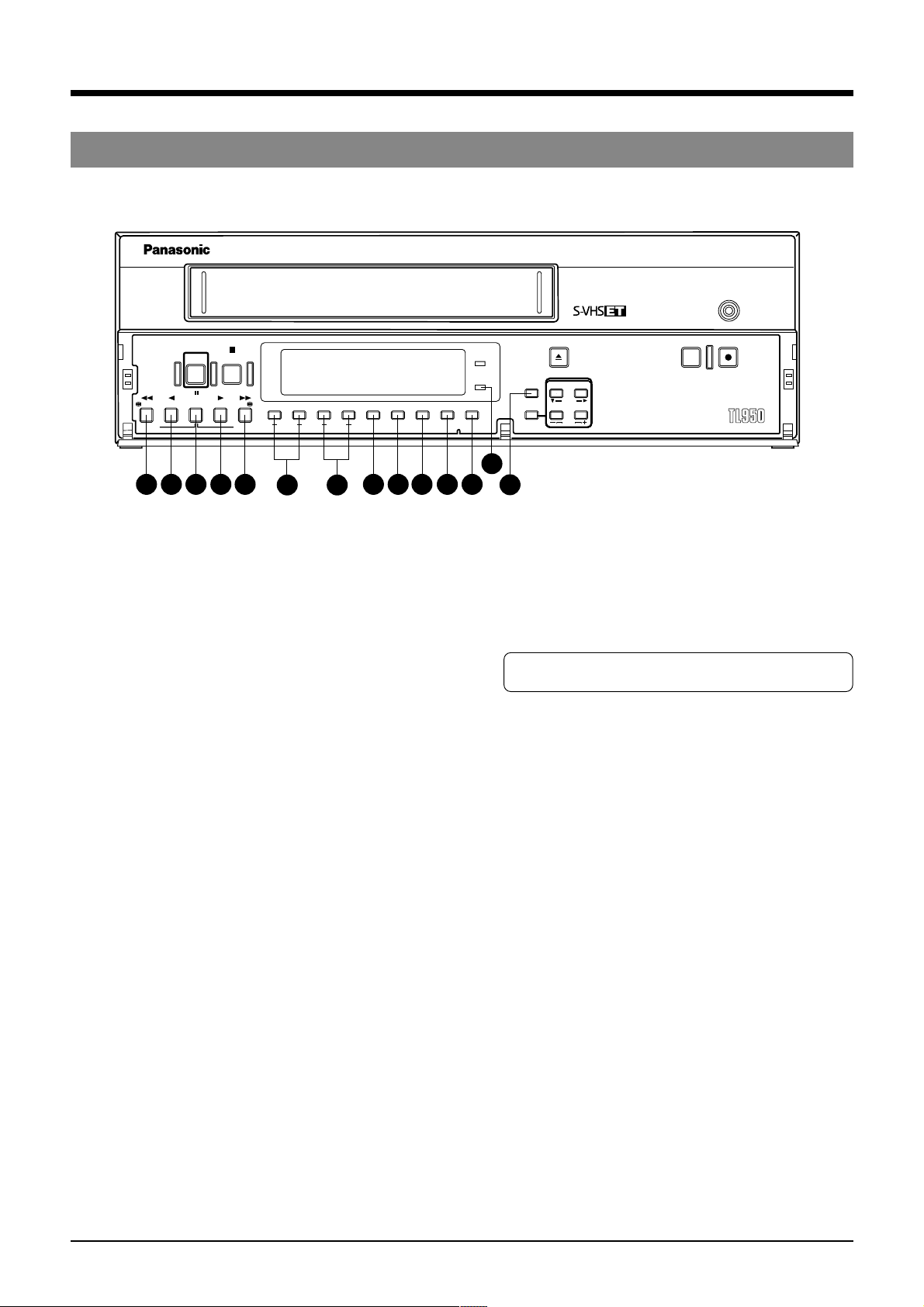
! [TIME MODE/SET +/–] buttons
• Use to select the recording and playback speed mode.
Available recording/playback speed modes vary
depending on the setting of menu switch <HIGH DENSITY
REC> on the <VTR MODE> screen.
Each time these buttons are pressed, the recording/
playback speed mode changes as follows. The recording/
playback speed mode is shown on the display.
S-VHS tape VHS tape
HDR recording HDR recording Playback speed
On Off On Off
2H* 2H 2H* 2H Standard
6H 6H* 6H 6H* 3x
— L12H ——12-hour SP linear slow
L18H ———18-hour EP linear slow
— L24H ——24-hour SP linear slow
— 24H — 24H 24-hour SP timelapse
24H — 24H — 24-hour EP timelapse
— 48H — 48H 48-hour SP timelapse
48H — 48H — 48-hour EP timelapse
— 72H — 72H 72-hour SP timelapse
72H — 72H — 72-hour EP timelapse
— 84H — 84H 84-hour SP timelapse
84H — 84H — 84-hour EP timelapse
— 120H — 120H 120-hour SP timelapse
120H — 120H — 120-hour EP timelapse
— 168H — 168H 168-hour SP timelapse
168H — 168H — 168-hour EP timelapse
— 240H — 240H 240-hour SP timelapse
240H — 240H — 240-hour EP timelapse
— 480H — 480H 480-hour SP timelapse
480H — 480H — 480-hour EP timelapse
— 960H — 960H 960-hour SP timelapse
960H — 960H — 960-hour EP timelapse
• The speed selection display - when a cassette tape is not
yet inserted - becomes a display when the S-VHS tape is
being used. If the VHS cassette tape is inserted after
setting the speed that can only be selected during the
time the S-VHS tape is used, it automatically changes
over to the speed that can be selected when the VHS tape
is being used.
Example: If the VHS tape is inserted - when a cassette
tape is not yet inserted - after selecting L18H,
the recording speed comes to 24H mode.
@ [MENU] button
Press to display the date/time, timer program, and various other
menu setting screens, as well as the hour meter, on the
monitor. Press again to cancel the menu or hour meter display.
10
51 2 3
REC
REC REVIEW REC
AG-
7
6
9
2 CONTROLS AND CONNECTORS
2-1 Front Panel
STOP
POWER
PAUSE/
/REW
REV PLAY
REV ADV FWD ADV
25
24
STILL
23
PLAY FF/
22
21
TRACKING
20 19
V. LOCK
TIMER
18
SEARCH COUNTER
POWER
HDR
LOCK CNT RESET
14151617
26
EJECT
RESET
CANCEL
MENU TIME MODE
13
/
ON SCREEN
SHIFT
SET
REC
REC REVIEW REC
AG-
# [RESET/CANCEL] button
• In the Timer Program Setting mode, press this button to
cancel the program settings. For details, refer to “Timer
Recording” on page 36.
• Also press this button to interrupt alarm recording or to
reset the alarm input data or power loss (power failure)
data. For details, refer to pages 21 and 39.
• Resets the seconds in the currently displayed time to 00
when pressed together with the
$ [CNT RESET] button
(except in menu setting mode).
- When the seconds value is 29 or less, the minutes value
is the same but the seconds value is reset to 0. (eg.
12:34:29 [ 12:34:00)
- When the seconds value is 30 or more, the seconds value
is reset to “00” and the minutes value is increased by one.
(e.g. 12:34:30 [12:35:00)
$ [CNT RESET] button
When the display shows the control tape counter or reel tape
counter, press this button to reset to “00
H00M00S” or “0000”.
% [LOCK] button
Press to activate the operation lock function.
^ [COUNTER] button
Selects which data — current time, control tape counter
H 00M 00S — 23H 59M 59S) or reel tape counter (0 —
(00
9999) — is displayed. Each time this button is pressed, the
display switches to the next item.
& [SEARCH] button
Use to search the alarm recorded section or a section
recorded at a specified date and time. In the Stop mode,
select the search mode by pressing this button.
• Press once to engage the Alarm Search mode.
• Press twice to engage the Alarm Scan mode.
• Press three times to engage the Date/Time Search mode.
• Press four times to release the search mode.
After the search mode is selected with this button, press
the [FF] or [REW] button to execute the search operation
in the selected mode.
For details, refer to page 49.
* [TIMER] button
Normally use this button for timer recording. For details,
refer to “Timer Recording” on page 31.
( [V. LOCK +/–] buttons
Press to reduce vertical picture jitter in the Still, Field
Advance Playback and Linear Slow Timelapse Play modes.
) [TRACKING +/–] buttons
If picture noise appears during play or field advance, press
these buttons to adjust tracking so that noise is reduced.
When the [+] and [–] buttons are pressed simultaneously,
tracking is reset to the preset level.
* You cannot make any tracking adjustment at L12H and
L24H Linear Slow Time-lapse Playback modes.
q [FF] button
• Press to fast-forward the tape.
• Starts fast-forward search when pressed in the Play mode.
• Starts forward alarm search or date/time search when the
Search mode is specified with the
& [SEARCH] button.
• Also controls field-by-field playback in the forward direction.
w [PLAY] button
• Press to play back the tape.
e [PAUSE/STILL] button
• Engages the Record-Pause mode when pressed in the
Record mode.
• Displays a still picture when pressed in the Play mode.
• Field advance or reverse playback is executed each time
the [FF] or [REW] button is pressed while pressing this
button in the Still mode. (When the [FF] or [REW] button
is pressed for more than 2 seconds, Continuous Field
Advance Playback mode is engaged. After about 3
minutes, the Stop mode is engaged.)
r [REV PLAY] button
Starts reverse playback when pressed in any mode except
Record, Record-Pause and Record Check.
t [REW] button
• Press this button to rewind the cassette.
• Starts rewind search when pressed in the Play mode.
• Starts reverse alarm search or date/time search when
the Search mode is specified with the
& [SEARCH] button.
• Also controls field-by-field playback in the reverse direction.
y [HDR] indicator
Lights in the HDR recording and HDR playback modes.
* HDR: High Density Recording
• For details on HDR recording, refer to page 28.
10
2 CONTROLS AND CONNECTORS
2-2 Display
1 6
7
2 3
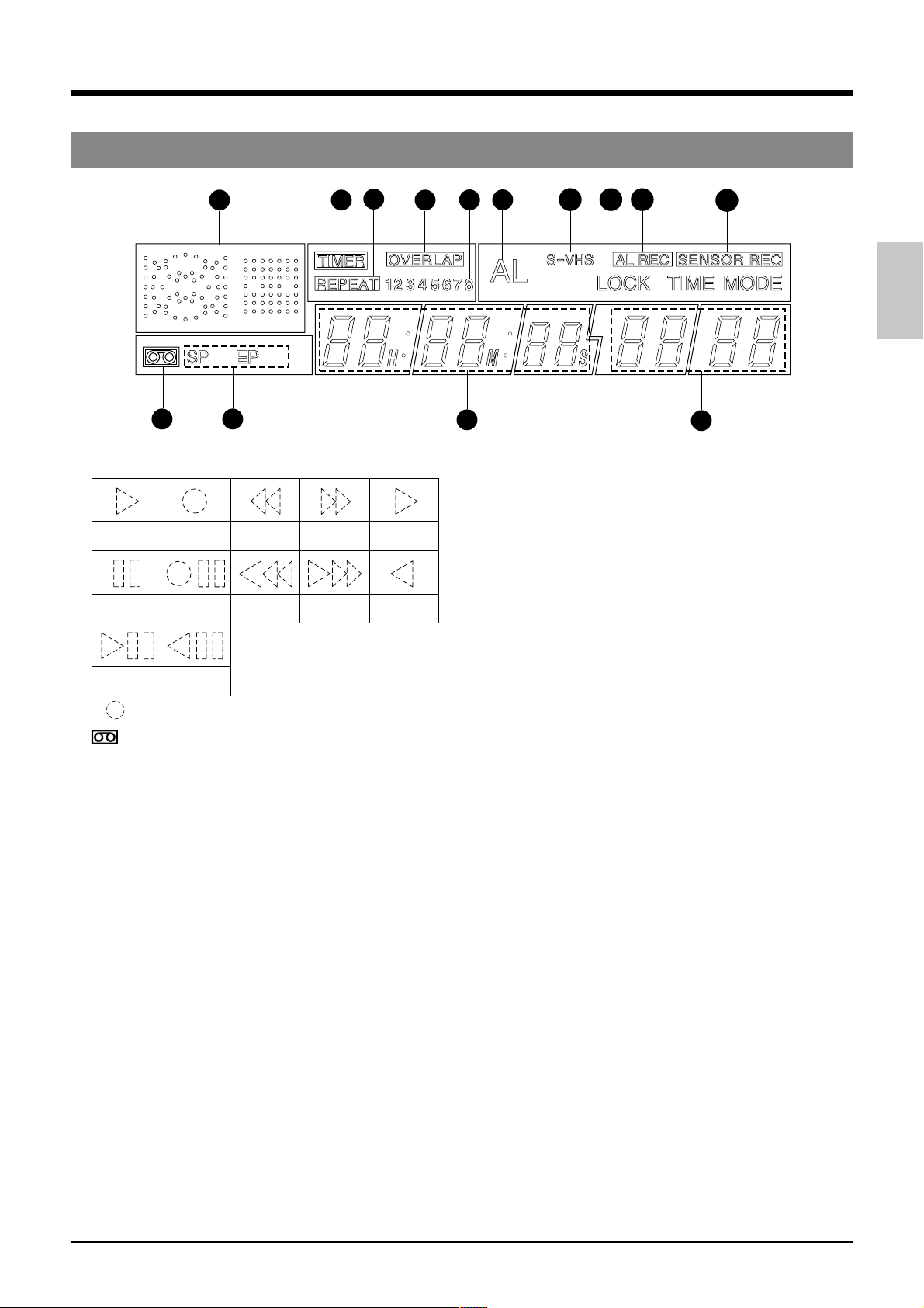
1 Operation mode display
Shows the operation modes.
Playback Recording
Still
Field-by-field
playback
* (
) mark in the Rec/Pause mode is shown in red.
Recordpause
Reverse step
slow playback
Rewind
Rewind
search
Fastforward
Fast-forward
search
2 Cassette indication
Lights when a cassette is loaded. Blinks when a cassette
is being ejected.
3 [SP/EP] indication
Shows the standard (SP) mode or extended (EP) mode
during recording/playback. During ordinary timelapse
recording/playback, the [SP] indication is shown.
The [EP] indication is shown during recording in the HDR
(High-Density Record) mode or during playback of a tape
section recorded in the HDR mode.
4 Tape counter/clock indication
• Shows the current time (hour: minute: second), tape
control counter (00H 00M 00S — 23H 59M 59S) or tape
reel counter (0 — 9999) when the operating mode is on.
The display can be selected with the [DISPLAY] button.
Shows the current time when the operating mode is off.
When a cassette is ejected, the tape control counter and
tape reel counter are reset automatically.
• When the cassette is rewound to the beginning in the
Repeat Recording or Auto Rewind mode using the counter
end output function, the tape control counter and tape
reel counter are reset.
• The control and reel counter counts slowly in the Timelapse
mode.
• In the timelapse mode, the control counter shows the time
equivalent to that shown when a tape is played back in the
2H or 6H mode.
(Example: The control counter advances 1 second for
about 8 minutes in the 960H ordinary timelapse mode.)
• During date/time search setting and operation, “td” is
shown in place of the seconds.
• Shows the setting item during menu switch setting.
Timelapse
playback
Reverse
playback
10
9
8
4
13
1211
14
13
5
5 Recording/playback speed display
• Normally shows the recording/playback speed mode set
with the [TIME MODE] button.
•
Shows the following indications in the Alarm Search mode.
During alarm search: Shows the specified alarm number
(example: AL12)
During alarm scan: Shows the alarm scan mode (ALSC).
During date/time search: Shows the specified date and
time (example 2310).
• Shows setting details in menu switch setting.
• When an error occurs, the error indication “E-**” blinks (if
the menu switch <WARNING> on the <FRONT DISPLAY>
screen is set to “ON”).
For error indications, refer to page 53.
6 [TIMER] indication
Lights during timer recording programming/operation.
7 [REPEAT] indication
When <REPEAT REC> in the <VTR MODE> menu is set
to “ON”, this indication is shown. When <TAPE END
MODE> in the <ALARM/SENSOR MODE> menu is set to
“STOP” and the Repeat Record mode is engaged, the
[REPEAT] indication goes out if alarm recording or sensor
recording takes place.
8 [OVERLAP] indication
Blinks when programs scheduled for timer recording overlap.
9 Timer program number
All programmed timer recording numbers light.
During timer recording, the number of the program being
recorded blinks. When the timer recording ends, this
number goes out.
0 [AL] (alarm) indication
Shown during alarm recording or sensor recording.
Blinks when alarm recording or sensor recording ends.
! [S-VHS] indication
Lights when a S-VHS cassette is loaded. In the playback
mode, it lights during playback of a tape recorded in the SVHS mode.
@ [LOCK] indication
Lights when the operation lock function is activated.
# [AL REC] (alarm recording) indication
Lights when the menu switch <REC MODE> on the <ALARM/
SENSOR MODE> screen is set to “ALARM” or “AL/
SENSOR”.
$ [SENSOR REC] (sensor recording) indication
Lights when the menu switch <REC MODE> on the <ALARM/
SENSOR MODE> screen is set to “SENSOR” or “AL/
SENSOR”.
11
2 CONTROLS AND CONNECTORS
2-1 FRONT PANEL
2-3 Rear Panel
64
8
1
RS-232C
AUDIO
SPARE
MIC
2
IN
OUT
3
5
7
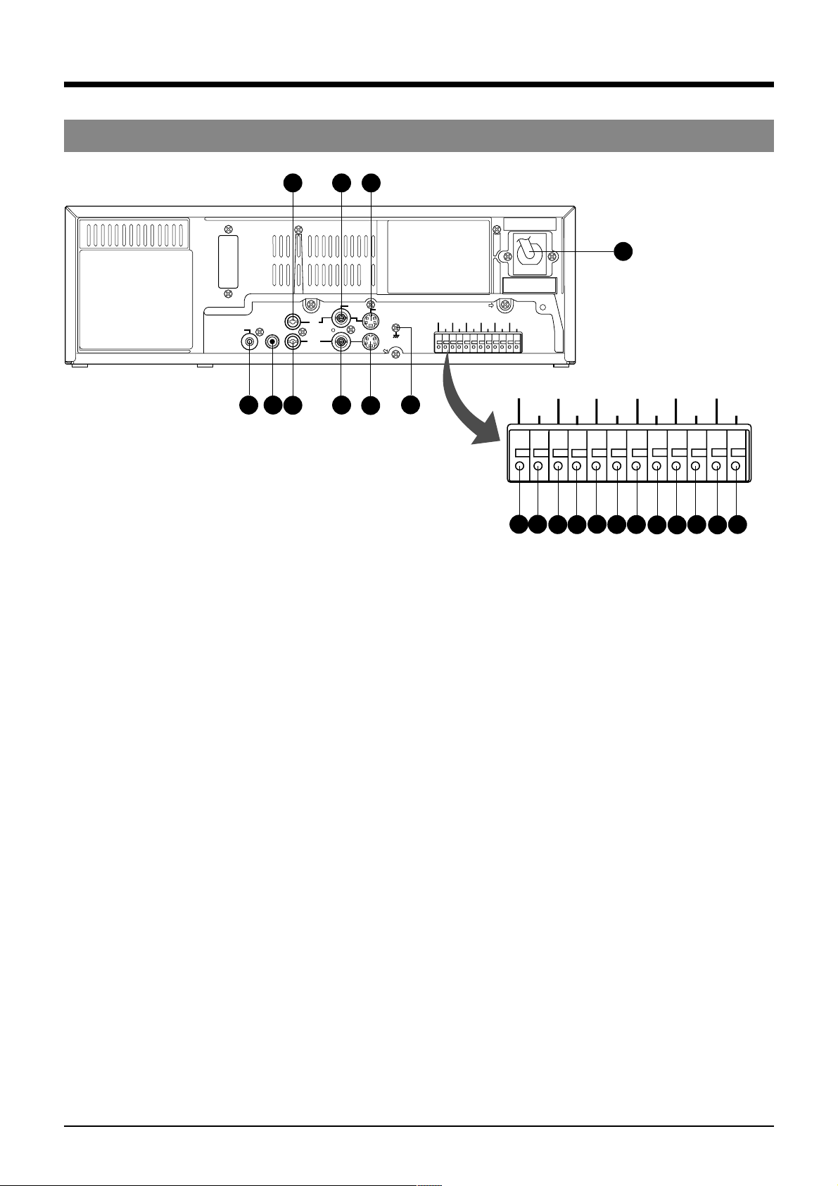
1 [AC IN] connector
Connect to an AC 120 V, 50 Hz/60 Hz socket using the
AC mains cable.
2 [SPARE] spare connector
This connector is not used now and thus has on
function.
3 [MIC] mic input connector
Connect a microphone with 3.6-mm dia. plug. When
signals are input from both the microphone connector
and the audio input connector, audio signals are mixed
and recorded.
4 [AUDIO IN] audio input connector (Phono)
Receives audio signals from a connected audio source.
5 [AUDIO OUT] audio output connector (Phono)
Outputs audio signals. No signal is output in the
Timelapse Recording/Playback mode.
6 [VIDEO IN] video input connector (BNC)
Receives composite video signals from a connected
camera or other video source.
• For composite video signal input, set the <INPUT>
menu switch in <VIDEO MODE> to LINE.
7 [VIDEO OUT] video output connector (BNC)
Outputs composite video signals. Even when the power
is not supplied to this unit, input signals (composite
video signals) from a camera can be output through this
connector (Operating mode-Off Video Throughout
function).
8 [S-VIDEO IN] S-VIDEO input terminal (4 pin)
Inputs separate Y/C signals.
• For separate Y/C signal input, set the <IN> menu
switch in <VIDEO MODE> to “S-VIDEO”.
VIDEO
AC~IN
S-VIDEO
9
10
CAM SW
OUT
COM
ALARM
CLOCK
COM
END OUT
SERIES
RESET IN
REC IN
WARNING
SERIES
CLOCK
TAPE
OUT
REC OUT
RESET OUT
COM
CLOCK
CLOCK
RESET OUT
1918
20
SERIES
REC IN
21
SERIES
REC OUT
22
CAM SW
OUT
1211
COM
ALARM
IN
ALARM
RESET
ALARM
REC OUT
1413
15
TAPE
END OUT
16
WARNING
17
RESET IN
OUT
ALARM
REC OUT
IN
ALARM
RESET
9 [S-VIDEO OUT] S-VIDEO output terminal (4 pin)
Outputs separate Y/C signals.
0 Signal ground terminal
This ground terminal is not provided for safety purposes.
It is used to ground signals. Connect this terminal to
ground the signal between VCRs.
! [CAM SW OUT] camera switching signal output
terminal
When a sequential switcher is connected, this terminal
outputs camera switching timing control signals. For
details on these signals, refer to page 56.
@ [COM] common ground terminal
Connect to the signal ground terminal of a connected
unit.
# [ALARM IN] alarm signal input terminal
Receives signals to start alarm or sensor recording.
$ [ALARM RESET] alarm signal reset input terminal
Receives signals to cancel alarm recording.
* Alarm input data is not reset.
% [ALARM REC OUT] alarm recording mode signal
output terminal
Outputs +12 V signals during alarm recording.
12

2 CONTROLS AND CONNECTORS
2-3 Rear Panel
^ [TAPE END OUT] tape end signal output terminal
Outputs a signal when the tape ends during recording.
If the menu switch <CNT TAPE END> on the <SRI/EXT
MODE> screen is set, signals are output when the
specified tape reel counter value is exceeded.
• Outputs a +12 V signal during recording. When the
tape ends or the specified counter value is passed,
a 0 V (GND level) signal is output.
• When the tape ends during auto repeat recording or
auto rewind recording, 0 V signal is output for about 2
seconds.
• Connect an external alarm or buzzer via an external
interface.
• To cancel the output, press the [EJECT] button,
[PLAY] button, [FF] button or [REW] button.
& [COM] common ground terminal
Connect to the signal ground terminal of a connected
unit.
* [WARNING OUT] warning signal output terminal
Outputs warning signals (+12 V) when a tape running or
mechanism problem occurs.
( [CLOCK RESET IN] clock reset input terminal
Connect to a master clock or another AG-TL950P’s
[CLOCK RESET OUT] terminal. When the clock reset
signal is input, the time is automatically synchronized
with the master clock or another AG-TL950P’s clock.
However, the time difference between VCRs should be
within ±30 seconds.
When the clock reset signal is input, the clock in this unit
is reset as shown below.
• When the seconds value is 29 or less, the minutes
value is the same but the seconds value is reset to 0.
(eg. 12:34:29 —> 12:34:00)
• When the seconds value is 30 or more, the second
value is reset to 00 and the minutes value is increased
by one. (e.g. 12:34:30 —> 12:35:00)
) [CLOCK RESET OUT] clock reset output terminal
Outputs the clock reset signal.
The clock reset signal is output in the following cases.
• When the internal clock is at 0:00 or 12:00
When this unit is connected to another AG-TL950P’s
[CLOCK RESET IN] terminal, the other VCR’s clock
can be set to the clock in this unit. However, the time
difference should be within ±30 seconds.
q [SERIES REC IN] series recording/VCR activation
signal input terminal
Receives series recording signal or VCR activation
signal from an external control device.
Select the input signal with the menu switches in the
<SRI/EXT MODE> menu.
5 Series recording input
A series recording signal is input when [SRI/EXT
REC] is set to “SERIES”.
• Connect to another VCR’s series recording signal
output terminal.
• When the tape in the preceding VCR ends, a signal
is delivered to this terminal and recording starts
automatically.
When the menu switch <CNT TAPE END> on the
<SRI/EXT MODE> screen is set, the signals are
delivered when the specified tape reel counter
value is reached. Recording starts automatically.
5 VCR activation signal input
When [SRI/EXT REC] is set to “EXT”, recording is
started and stopped with an external signal.
• Connect to an external control device.
If a VCR activation signal (ground input) is input to
this terminal, the VCR starts recording
automatically and continues recording for as long
as the VCR activation signal is input.
w [SERIES REC OUT] series recording signal output
terminal
Outputs series recording signals.
A series recording signal is output when [SRI/EXT REC]
is set to “SERIES”.
• Connect to another VCR’s series recording signal
input terminal.
• Outputs a signal when the tape being recorded in this
unit ends.
When the menu switch <CNT TAPE END> on the
<SRI/EXT MODE> screen is set, the signals are
output when the specified tape reel counter value is
reached.
13
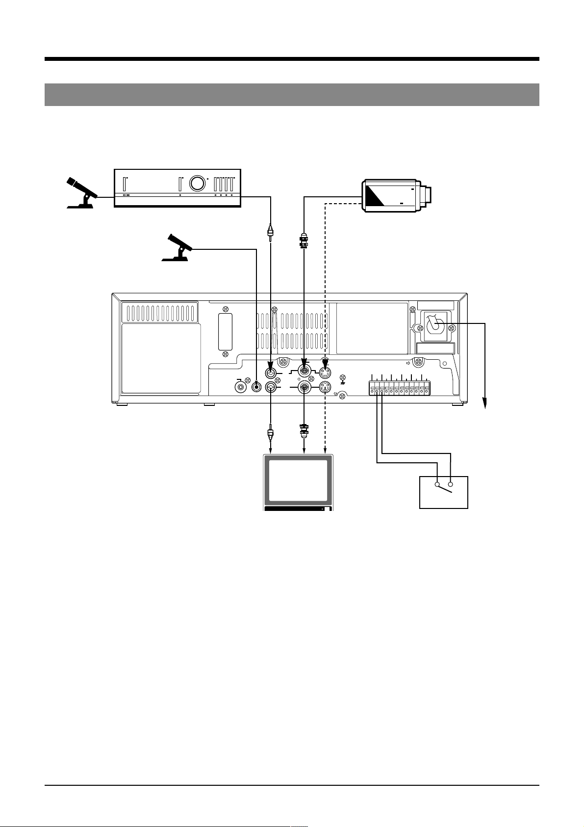
3 CONNECTIONS
3-1 Connecting to a Camera
Microphone
Amplifier
Microphone
CCD
Video camera
Phono
BNC
4pin
M3.5 minijack
CLOCK
SERIES
RESET IN
REC IN
SERIES
WARNING
CLOCK
REC OUT
OUT
RESET OUT
Alarm sensor
AC~IN
RS-232C
SPARE
MIC
Phono
AUDIO
IN
OUT
BNC
Monitor TV
VIDEO
S-VIDEO
4pin
CAM SW
OUT
COM ALARM IN
ALARM
ALARM
COM
REC OUT
IN
ALARM
TAPE
COM
RESET
END OUT
1 Connect the monitor’s video/audio input connectors to the AG-TL950P’s video/audio output connectors.
2 Connect the video camera’s video output connector to the AG-TL950P’s video input connector.
3 Input audio signals to the audio input connectors via an amplifier.
4 When connecting an alarm sensor, connect it to the AG-TL950P’s alarm input terminal.
5 When the connection is complete, connect the power plug to an AC 120 V, 50 Hz/60 Hz socket.
Mains cable
AC 120 V
50 Hz/60 Hz
14
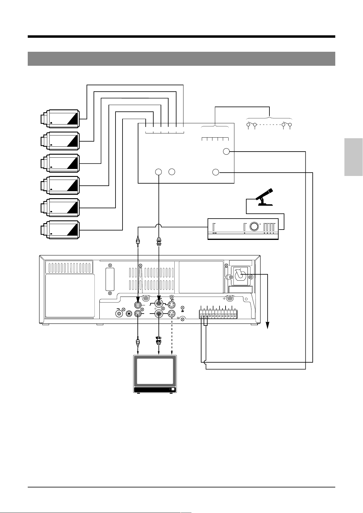
3 CONNECTIONS
3-2 System Using Sequential Switcher
Video camera
CCD
1 2 3 4 5 6
CCD
CCD
CCD
CCD
Video output
Alarm sensor input
1 2 3 4 5 6
Alarm signal output
Camera switching
signal input
Alarm sensor
Sequential switcher
Microphone
CCD
RS-232C
SPARE
Phono
MIC
Phono
BNC
AUDIO
IN
OUT
BNC
Monitor TV
VIDEO
S-VIDEO
CAM SW
OUT
4pin
CAM SW
OUT
ALARM
COM
ALARM
COM
RESET IN
REC OUT
IN
ALARM
WARNING
TAPE
RESET
OUT
END OUT
ALARM IN
CLOCK
SERIES
REC IN
CLOCK
RESET OUT
Amplifier
AC~IN
SERIES
REC OUT
Mains cable
AC 120 V
50 Hz/60 Hz
1 Connect video cameras and alarm sensor to a sequential switcher (frame switcher).
2 Connect the sequential switcher’s (frame switcher) alarm signal output, camera switching signal input and video output to
the AG-TL950P.
3 Connect the monitor’s video/audio input connectors to the AG-TL950P’s video/audio output connectors.
4 When the connection is complete, connect the power plug to an AC 120 V, 50 Hz/60 Hz socket.
5 Synchro should be applied to all connected video cameras.
6 If you are connecting the camera switching signal input from a sequential switcher (frame switcher) to the AG-TL950P, be
sure to set the <CAMERA SW> menu switch.
15
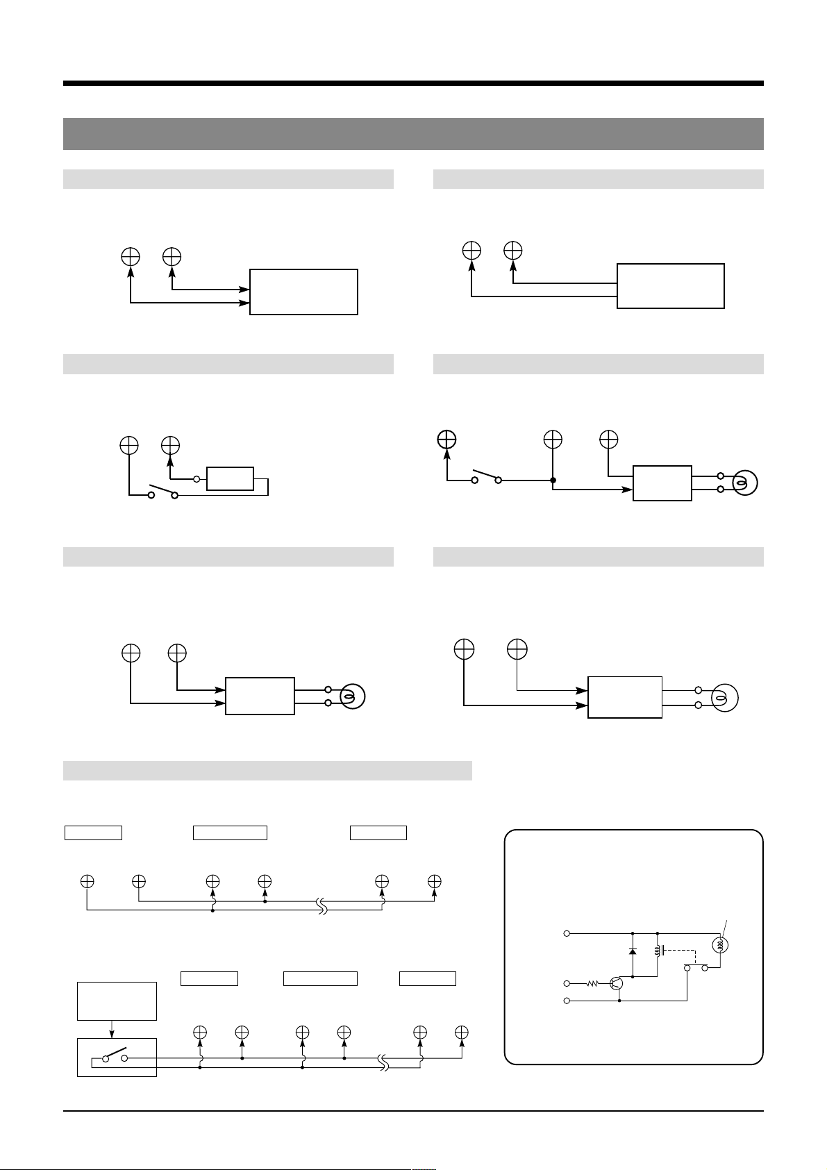
3 CONNECTIONS
3-3 Connecting the Rear Panel Input/Output Terminal Connections
[CAM SW OUT] camera switching signal output terminal
CAM SW
OUT
COM
Sequential switcher
camera switching
signal input
[ALARM RESET] alarm reset terminal
ALARM
RESET
COM
Vcc
Switch
Vcc: 5V–12V
[ALARM IN] alarm signal input terminal
ALARM
COMIN
Sequential switcher
alarm output
terminal
[ALARM REC OUT] alarm recording mode signal output terminal
ALARM
RESET
Switch
ALARM
REC OUT COM
External
interface
[TAPE END OUT] tape end output terminal [WARNING OUT] warning signal output terminal
Alarm
lamp
TAPE
END OUT
COM
Alarm lamp
External
interface
[CLOCK RESET] clock reset terminal
5 When setting the clock to the first VCR’s clock
First VCR Second VCR Last VCR
CLOCK
OUT
CLOCK
INCOM
COM
CLOCK
IN
5 When setting the clock to the external master clock
First VCR Second VCR Last VCR
External
master clock
CLOCK
IN
COM
CLOCK
COM
IN COM
WARNING
COM
CLOCK
IN
OUT
COM
Alarm lamp
External
interface
External interface example
Example: Lamp lights with HIGH signal
Power
supply
Control
signal
GND
(Lamp, etc.)
Relay
16
5 Use appropriately rated devices.
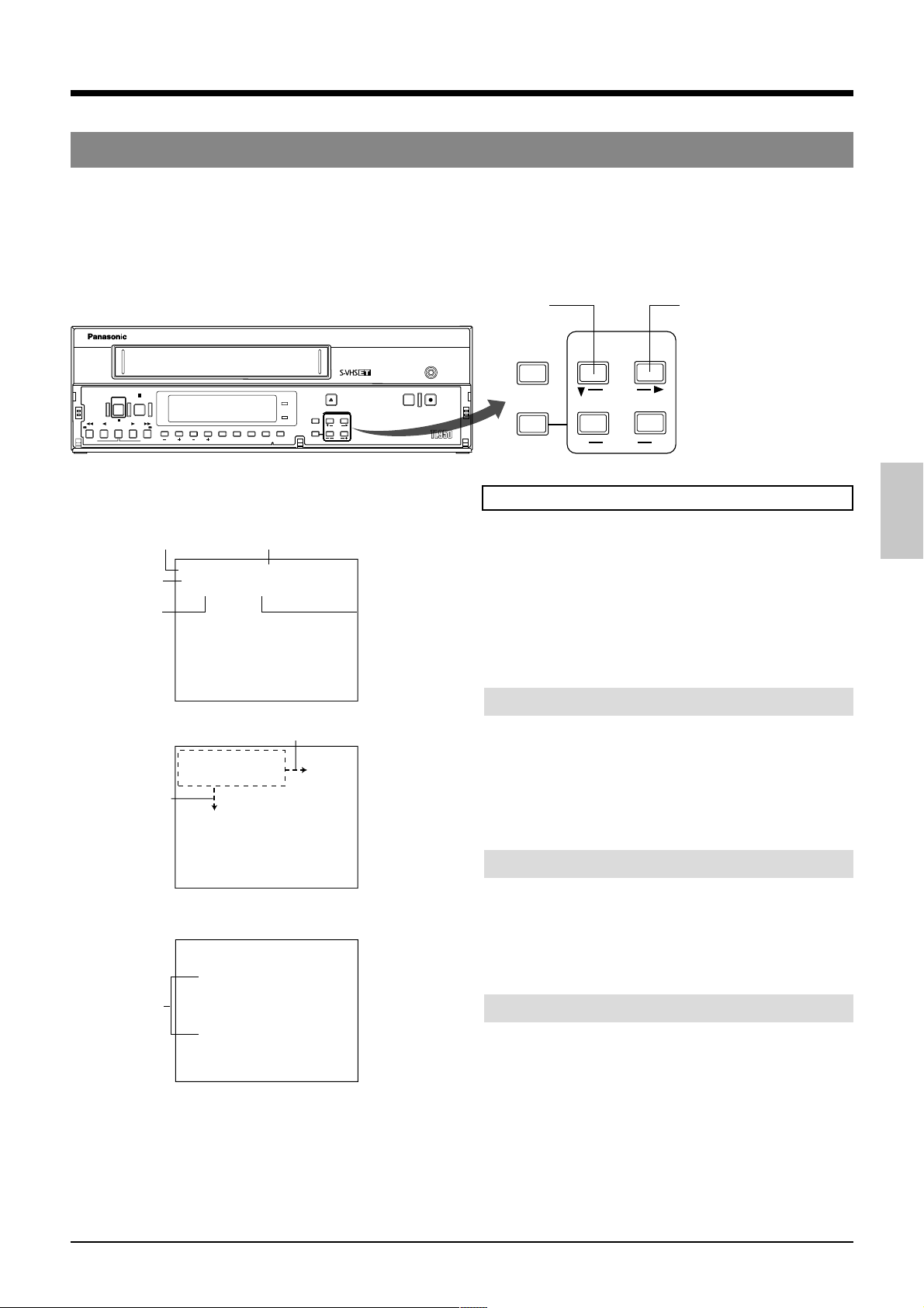
4 ON-SCREEN/MENU SWITCHES
4-1 On-Screen Display
Displays the time date (date and time), recording speed, number of alarms and number of power losses (power failures) on
screen in the Stop mode, Record mode and Record-Pause mode.
During recording, the on-screen data is recorded together with video signals.
• The on-screen display position can be moved with the [ON SCREEN] buttons.
• The type of data shown and display brightness can be selected on the <ON SCREEN /FRONT DISPLAY MODE> screen.
STOP
POWER
PAUSE/
/REW
PLAY FF/
REV PLAY
STILL
REV ADV FWD ADV
Time (hour,
minute, second)
Date (month,
day, year)
Number of
alarms
[ON SCREEN 7]
button
Display items
POWER
TIMER
SEARCH COUNTER
TRACKING
V. LOCK
LOCK CNT RESET
On-screen display
Recording speed (T-MODE)
ALARM indication during
alarm/sensor recording
H
4
2
0
0
:
0
2
1
–
2
L
A
–
0
Z
*
O
O
M
*
A
C
D
*
T
A
D
*
R
U
*
*
*
*
*
*
*
*
*
*
*
*
*
*
*
*
*
I
F
4
*
:
*
0
0
*
1
I
R
F
*
–
9
4
1
9
9
4
0
–
L
P
6
5
*
L
B
O
M
N
U
*
R
*
E
E
H
E
*
E
*
B
*
*
*
*
*
*
*
*
*
*
*
*
N
E
D
*
*
*
*
.
M
*
*
*
E
L
E
T
*
*
*
E
R
U
*
*
E
D
N
A
*
*
*
*
*
*
*
*
*
*
*
*
*
*
*
*
*
*
*
*
*
*
*
*
*
*
*
*
*
U
N
E
M
*
[ON SCREEN t] button
0
:
0
1
*
0
0
0
–
1
2
–
A
L
O
*
Z
A
*
M
A
*
D
U
*
D
*
*
*
*
*
*
*
*
*
*
*
*
F
4
*
*
:
*
2
4
2
4
1
–
0
5
*
6
O
M
N
O
C
R
*
*
T
E
H
E
R
*
E
*
*
*
*
*
*
*
*
*
*
*
*
*
*
*
*
*
D
I
N
H
9
9
9
*
F
R
B
U
T
E
B
*
*
*
*
E
I
L
P
L
–
0
4
M
.
*
*
*
*
E
L
E
*
*
*
U
R
E
*
*
*
A
N
D
E
*
*
*
*
*
*
*
*
*
*
*
*
*
*
*
*
*
*
*
*
*
*
*
*
*
*
*
M
E
N
U
*
ON SCREEN MODE screen
*
*
*
*
[
O
N
S
C
R
E
E
N
1
T
O
.
N
E
E
*
A
N
M
U
.
*
2
D
A
.
T
E
N
3
T
I
.
M
E
*
4
T
-
.
M
O
D
5
A
L
.
A
R
M
P
6
O
W
.
E
R
M
O
*
D
[
M
F
R
R
1
E
C
.
*
T
W
2
A
R
.
N
I
4
F
*
I
N
*
D
*
*
*
*
*
*
*
*
B
L
A
N
C
*
*
U
M
.
*
*
*
*
T
E
L
E
*
*
*
E
*
*
*
B
C
N
T
E
*
*
L
O
S
S
*
C
O
N
T
*
D
I
S
A
L
L
Y
*
*
*
N
G
*
*
*
*
*
E
*
M
E
N
U
*
[ON SCREEN 7] button
RESET/
REC
EJECT
/
RESET
HDR
CANCEL
ONSCREEN
SHIFT
MENU TIMEMODE
SET
REC REVIEW REC
AG-
CANCEL
MENU
ON SCREEN
SHIFT
TIME MODE
–
SET
[ON SCREEN t] button
+
Preparation
5 Connect the video output connector of this unit to the
monitor’s video input connector.
*
*
*
*
*
*
*
*
*
*
*
*
*
*
*
*
*
*
*
*
*
O
*
T
*
U
A
*
*
*
*
*
*
*
*
.
M
*
*
*
Number of
*
*
*
*
*
.
A
*
*
*
*
*
*
*
*
*
*
*
*
*
*
*
*
*
*
*
*
*
*
*
*
*
*
*
*
*
*
*
*
*
*
*
*
*
*
*
*
*
*
*
*
*
*
*
*
*
*
*
*
*
*
*
*
*
*
*
*
*
*
*
*
*
*
*
*
*
*
*
*
1
*
*
*
*
*
*
O
*
*
*
O
*
*
O
*
*
O
*
*
O
*
*
*
*
*
*
O
*
*
*
O
*
*
*
power losses
*
*
(power
*
*
failures)
*
*
*
*
*
*
*
*
*
*
*
*
*
*
*
*
*
*
*
*
*
*
*
*
*
*
*
*
*
*
*
*
*
*
0
0
*
*
N
N
N
N
N
*
*
N
N
*
*
*
5
*
4
T
*
*
*
*
*
*
*
*
*
*
*
*
*
*
*
*
*
*
*
*
*
*
*
*
*
*
*
*
*
*
*
*
*
*
*
A
U
*
T
O
M
.
*
*
*
A
.
*
*
*
*
*
*
*
*
T
*
4
5
*
*
*
*
*
*
*
*
*
*
*
*
*
*
*
*
*
*
*
*
*
*
*
*
*
*
M
O
D
E
]
*
*
*
*
*
*
*
*
*
*
*
M
.
*
*
*
A
.
*
*
*
*
*
*
*
*
T
4
5
*
N
T
I
N
E
P
L
A
Y
]
*
*
*
*
*
*
*
*
*
*
*
*
*
*
*
1 Turn on the monitor and VCR.
2 When a video signal from a camera is input to the video
input connector, on-screen data is superimposed on the
picture.
When there is no input signal, on-screen data is shown
on a black background.
Changing the on-screen display position
5
Move horizontally.
Press the [ON SCREEN t] button.
[ The display position is moved to the right
5 Move downward.
Press the [ON SCREEN 7] button.
[ The display position is moved down.
Selecting the data display
The data displayed on-screen can be selected on the <ON
SCREEN MODE> screen.
Set the <ONSCREEN/F. DISP MODE> setting to “ON”.
5 When you do not want to display or record on-screen
data, set the corresponding menu item to “OFF”.
Changing the on-screen display brightness
Set the brightness with the menu switch <TONE> on the
<ON SCREEN MODE> screen. Select 0, 30, 70 or 100.
• The higher the number, the brighter the characters.
* For details on menu operation, refer to page 22.
17
4 ON-SCREEN/MENU SWITCHES
4-2 Main Menu Display
You can display date and time data recorded when an alarm input or power failure occurs, as well as the hour meter (drum
rotating time) by selecting the desired item in the main menu.
The date/time setting screen, menu switch setting screen for each application, and timer recording program setting screen can
also be displayed by selecting the desired item in the main menu.
Date/time setting, menu switch setting and hour meter can be checked on the VCR’s display as well.
POWER
HDR
CNT RESET
[MENU] button
*
*
*
*
*
*
*
*
*
*
*
*
EJECT
/
RESET
CANCEL
ON SCREEN
SHIFT
MENU TIMEMODE
SET
[SET +] button
[SET –] button
Main menu screen
*
*
*
*
*
*
[
M
T
I
O
N
V
I
S
R
A
L
B
U
P
R
H
O
H
O
A
L
E
M
E
A
D
J
U
S
C
R
E
E
N
/
D
E
O
/
V
T
R
I
/
E
X
T
*
M
A
R
M
/
S
E
N
Z
Z
E
R
/
I
N
O
G
R
A
M
*
T
L
I
D
A
Y
*
S
U
R
M
E
T
E
A
R
M
*
R
E
C
[SHIFT t] button[SHIFT 7] button
Operation
5 Connect the video output connector of this unit to the
REC
REC REVIEW REC
AG-
N
U
]
*
*
*
*
*
*
*
*
*
*
S
T
*
*
*
F
.
D
I
S
*
M
O
D
E
O
D
E
*
*
S
O
R
*
M
*
O
U
T
*
I
M
E
R
*
E
T
*
*
*
R
*
*
*
*
A
L
L
/
P
*
*
*
*
*
*
*
*
*
*
P
*
M
O
D
E
*
*
*
*
*
*
*
*
*
*
*
*
O
D
E
*
*
O
*
*
*
*
*
O
*
*
*
*
*
*
*
*
*
*
*
*
*
*
*
*
*
O
O
W
E
R
*
L
Cursor
*
*
*
*
*
*
*
*
*
N
N
N
N
N
N
*
*
*
*
*
*
N
N
N
S
S
O
monitor’s video input connector.
1 Turn on the monitor and VCR.
2 Press the [MENU] button.
[ The main menu screen is shown on the monitor
screen.
3 Press the [SHIFT 7] button to move the cursor to the
item you want to display.
4 Press the [SET +/–] button to display the selected menu
screen on the monitor (see below).
5 To restore the main menu screen, press the [MENU]
button.
To cancel the main menu mode, press the [MENU]
button again. The normal screen is restored.
Contents of the main menu items
5
TIME ADJUST (VCR's display T ADJ)
Displays the date/time setting screen.
* Set the clock before operating the VCR (refer to
page 19).
5 ONSCREEN/FRONT DISPLAY MODE
(VCR's display DiSP)
Let’s you choose whether or not to display onscreen display items, brightness selection, [REC]
indicator and warning indicator.
5 VIDEO/VTR MODE (VCR's display ViDEO)
For VCR operation settings such as V. Pulse ON/
OFF, HDR recording, counter memory function and
repeat recording/playback.
5 SRI/EXT MODE (VCR's display SRi ET)
For setting series recording or automatic recording
with an external signal.
5 ALARM/SENSOR MODE (VCR's display AL 5EN)
For setting alarm recording or sensor recording
operation.
18
5 BUZZER/IN OUT (VCR's display BU22iO)
Turn ON/OFF buzzers such as the tape end buzzer
and alarm/sensor buzzer and set camera switch
signal output.
5 PROGRAM TIMER (VCR's display PRG)
Shows timer recording program settings with the day
of the week.
5 HOLIDAY SET (VCR's display HOLiDY)
Shows timer recording program settings at specified
dates.
5 HOUR METER (VCR's display HOUR)
Shows the VCR’s operating time (drum rotation time).
5 ALARM RECALL/POWER LOSS
(VCR's display AL P0)
Shows the date and time when an alarm was input or
a power failure occurred.
 Loading...