

Page 1

Operating
Instructions
PAL
Time Lapse Recorder
B
Model AG-
E
Before attempting to connect, operate or adjust this product, please read these instructions completely.
Page 2

Caution for AC Mains Lead
FOR YOUR SAFETY PLEASE READ THE FOLLOWING TEXT CAREFULLY.
FOR U.K. ONLY
This appliance is supplied with a moulded three pin
mains plug for your safety and convenience.
A 5 amp fuse is fitted in this plug.
Should the fuse need to be replaced please ensure that
the replacement fuse has a rating of 5 amps and that it
is approved by ASTA or BSI to BS1362.
Check for the ASTA mark or the BSI mark on the
body of the fuse.
If the plug contains a removable fuse cover you must
ensure that it is refitted when the fuse is replaced.
If you lose the fuse cover the plug must not be used
until a replacement cover is obtained.
A replacement fuse cover can be purchased from your
local Panasonic Dealer.
IF THE FITTED MOULDED PLUG IS UNSUITABLE
FOR THE SOCKET OUTLET IN YOUR HOME THEN
THE FUSE SHOULD BE REMOVED AND THE PLUG
CUT OFF AND DISPOSED OF SAFELY.
THERE IS A DANGER OF SEVERE ELECTRICAL
SHOCK IF THE CUT OFF PLUG IS INSERTED INTO
ANY 13 AMP SOCKET.
AA
As the colours of the wires in the mains lead of this
appliance may not correspond with the coloured markings identifying the terminals in your plug, proceed as
follows:
The wire which is coloured BLUE must be connected
•
to the terminal in the plug which is marked with the
letter N or coloured BLACK.
The wire which is coloured BROWN must be con-
•
nected to the terminal in the plug which is marked with
the letter L or coloured RED.
Under no circumstances should either of these wires
•
be connected to the terminal in the plug which is
marked with the letter E or by the Earth symbol .
How to replace the fuse
1. Open the fuse compartment with a screwdriver.
If a new plug is to be fitted please observe the wiring
code as shown below.
If in any doubt please consult a qualified electrician.
IMPORTANT: The wires in this mains lead are coloured
in accordance with the following code:
Blue:
Brown:
■
DO NOT REMOVE PANEL COVER BY UNSCREWING.
To reduce the risk of electric shock, do not remove
cover. No user serviceable parts inside. Refer servicing to qualified service personnel.
■
If the unit is not going to be used for a length of time,
turn the unit to STANDBY mode and disconnect the
power plug from the AC outlet.
Neutral
Live
WARNING:
TO REDUCE THE RISK OF FIRE OR SHOCK
HAZARD, KEEP THIS EQUIPMENT AWAY
FROM ALL LIQUIDS-USE AND STORE ONLY
IN LOCATIONS WHICH ARE NOT EXPOSED
TO THE RISK OF DRIPPING OR SPLASHING
LIQUIDS, AND DO NOT PLACE ANY LIQUID
CONTAINERS ON TOP OF THE EQUIPMENT.
2. Replace the fuse.
Fuse
CAUTION:
TO REDUCE THE RISK OF FIRE OR SHOCK
HAZARD AND ANNOYING INTERFERENCE, USE
THE RECOMMENDED ACCESSORIES ONLY.
CAUTION:
Do not install or place this unit in a bookcase,
built in cabinet or in another confined space in
order to keep well ventilated condition. Ensure
that curtains and any other materials do not
obstruct the ventilation condition to prevent
risk of electric shock or fire hazard due to
overheating.
is the safety information.
2
Page 3

Lithium Battery
Warning
The lithium battery in this equipment must only be replaced
by qualified personnel. When necessary, contact your local
Panasonic supplier.
“The lithium battery is a critical component (type number
VL2330/1HF manufactured by Panasonic.)
It must never be subjected to excessive heat or discharge.
It must therefore only be fitted in equipment designed
specifically for its use.
Replacement batteries must be of the same type and
manufacturer. They must be fitted in the same manner and
location as the original battery, with the correct polarity
connections observed.
Do not attempt to re-charge the old battery or re-use it
for any other purpose. It should be disposed of in waste
products destined for burial rather than incineration.”
CAUTION
Danger of explosion if battery is incorrectly replaced.
Replace only with the same or equivalent type recommended by the equipment manufacturer. Discard used
batteries according to manufacturer’s instructions.
VARNING
Explosionsfara vid felaktigt batteribyte. Använd samma
batterityp eller en ekvivalent typ som rekommenderas
av apparattillverkaren. Kassera använt batteri enligt fabrikantens instruktion.
ADVARSEL
Eksplosionsfare ved fejlagtig håndtering.
Udskiftning må kun ske med batteri af samme fabrikat
og type. Levér det brugte batteri tilbage til leverandøren.
VAROITUS
Paristo voi räjähtää, jos se on virheellisesti asennettu.
Vaihda paristo ainoastaan laitevalmistajan suosittelemaan tyypiin. Hävitä käytetty paristo valmistajan ohjeiden
mukaisesti.
Attention/Attentie
A battery is used for memory-backup in the unit. When the battery is
exhausted, you should not throw it away, but dispose of it as small chemical
waste.
Voor het reservegeheugen van het apparaat wordt gebruikgemaakt van een
batterij. Wanneer de batterij is uitgeput, mag u deze niet gewoon weggooien,
maar dient u deze als klein chemisch afval weg te doen.
Removing the battery/Verwijderen van de batterij
Battery for memory-backup (lithium battery)/
Batterij voor reservegeheugen (lithiumbatterij)
Remove the battery from the unit.
Verwijder de batterijhouder uti het apparaat.
Battery holder/
Batterijhouder
To replace the battery, please consult your local dealer.
Voor het vernieuwen van de batterij dient u uw plaatselijke handelaar te
raadplegen.
Lithium battery/Lithiumbatterij
3
Page 4

Contents
Features
. . . . . . . . . . . . . . . . . . . . . . .
Regular Maintenance Service
Recommendation
Parts And Their Functions
Menu Screens
Date and Time Settings
Time/Date Display Position
Time Mode Selection
Recording Procedure
Tips For Better Recording
Recording Mode Lock
•
Recording Check
•
Restoration-of-Power-After-Failure
•
Recording
Timer Recording
Internal Timer Recording
•
Daily Recording (Daily Timer)/
•
Weekly Recording (Weekly Timer)
External Timer Recording
•
. . . . . . . . . . . . . . . . . . .
. . . . . . . . . . . . . .
. . . . . . . . . . . . . . . . . . . .
. . . . . . . . . . . . . . .
. . . . . . . . . . . . .
. . . . . . . . . . . . . . . . .
. . . . . . . . . . . . . . . . .
. . . . . . . . . . . . . .
. . . . . . . . . . . . . .
. . . . . . . . . . . . . . . .
. . . . . . . . . . . . . . . . . . . .
. . . . . . . . . . . . . . . . . . . .
. . . . . . . . . . . .
. . . . . . . . . . . .
. . . . . . .
12
13
14
15
15
15
15
15
16
16
17
18
5
5
6
9
Auto Repeat Recording/Auto Rewinding
Alarm Recording (Emergency Recording)
Principle of alarm recording
•
Alarm and display methods during
•
alarm recording
Connecting the alarm input connector
•
Alarm recording operation
•
Alarm Recall
•
Playback Procedure
Tracking
•
Vertical hold adjustment
•
Routine & Regular Inspection Request
Troubleshooting
Specifications
. . . . . . . . . . . . . . . . . . . . .
. . . . . . . . . . . . . . . . . . . .
. . . . . . . . . . . . . . . . .
. . . . . . . . . . . . . . . . . .
. . . . . . . . . . . . . . . . .
. . . . . . . . . . . . . . . . . . .
. . . . . . . . . . .
. . . . . . . . . . .
. . . . . . . . . . . .
. . . . . . .
. . . . . .
. . . . .
. . . . . . .
18
19
19
19
19
20
20
21
21
21
22
23
25
■
Do not insert fingers or any objects into the video casette
holder.
■
Avoid operating or leaving the unit near strong magnetic
fields. Be especially careful of large audio speakers.
■
Avoid operating or storing the unit in an excessively hot,
cold, or damp environment as this may result in damage
both to the recorder and to the tape.
■
Do not spray any cleaner or wax directly on the unit.
■
If the unit is not going to be used for a length of time,
protect it from dirt and dust.
■
Do not leave a cassette in the recorder when not in use.
■
Do not block the ventilation slots of the unit.
■
Use this unit horizontally and do not place anything on
the top panel.
■
Cassette tape can be used only for one-side, one
direction recording. Two-way or two-track recordings
cannot be made.
■
Cassette tape can be used for either Colour or Black &
White recording.
■
Do not attempt to disassemble the recorder.
There are no user serviceable parts inside.
■
If any liquid spills inside the recorder, have the recorder
examined for possible damage.
■
Refer any needed servicing to authorized service
personnel.
4
Page 5

Features
Recording and playback up to 24-hour time modes
In addition to the 3-hour/6-hour time modes, recording
and playback can be performed in the time lapse modes
(12-hour, 24-hour modes).
Full line-up of recording functions
Included in the wide range of recording functions are
restoration-of-power-after-failure recording, recording
every day and by the days of the week using the internal
timer, external timer recording, alarm recording, emergency recording and repeat recording.
Playback functions
Among the convenient playback functions are the
recording review function for immediate viewing of
recorded material, the handy search function for locating
images promptly, and the forward/reverse field advance
and still-picture functions for careful viewing of particular
scenes.
Auto tracking function
The tracking can be automatically adjusted by pressing
the “–” and “+” tracking buttons together.
Built-in time/date generator
This unit comes with a built-in microprocessor with a
calendar function for displaying the time on the display
or TV monitor and for controlling the time of the internal
timer.
Recording lock function
A double recording mode lock function is provided for
safeguarding against operational errors during recording.
Connection to frame switcher
Easy connection to a frame switcher is possible once
the unit has been connected to the video input and
camera SW connectors.
•
Do not supply signals from colour cameras and blackand-white cameras simultaneously to the camera
input conectors since this may disturb the synchronization on the monitor screen or generate noise.
Hour meter
The unit contains an hour meter which provides useful
information for maintenance and inspections.
Remote control
The unit can be operated from a distance of about 5
meters if the AG-A11 remote controller, available as an
optional accessory, is connected.
IMPORTANT
“Unauthorized recording of copyrighted television
programmes, films, video tapes and other materials
may infringe the right of copyright owners and be
contrary to copyright laws.”
Regular Maintenance Service Recommendation
Although this unit is designed to withstand long-term use, the items listed below should be inspected regularly so
that the unit is kept in perfect working order. Use the hour meter to know when to conduct the inspections.
The VTR is a piece of precision-made equipment and, as such, it is recommended that the user enter into a
maintenance and inspection agreement to keep the unit operating free of trouble or failures. For further details,
please consult with your dealer.
Cumulative operation time
(hours)
Inspection item
Transport system cleaning
Audio heads
Video heads
Cylinder unit
Service life inspection
Cleaning
The above table merely serves to lay down general guidelines for the inspection of typical parts involved in regular
inspections. The timing of the inspections needs to be adjusted according to the VTR’s operating environment.
500 1000 1500 2000 2500 3000 3500
4000 8000 12000
(12-/24-hour mode use)
5
Page 6
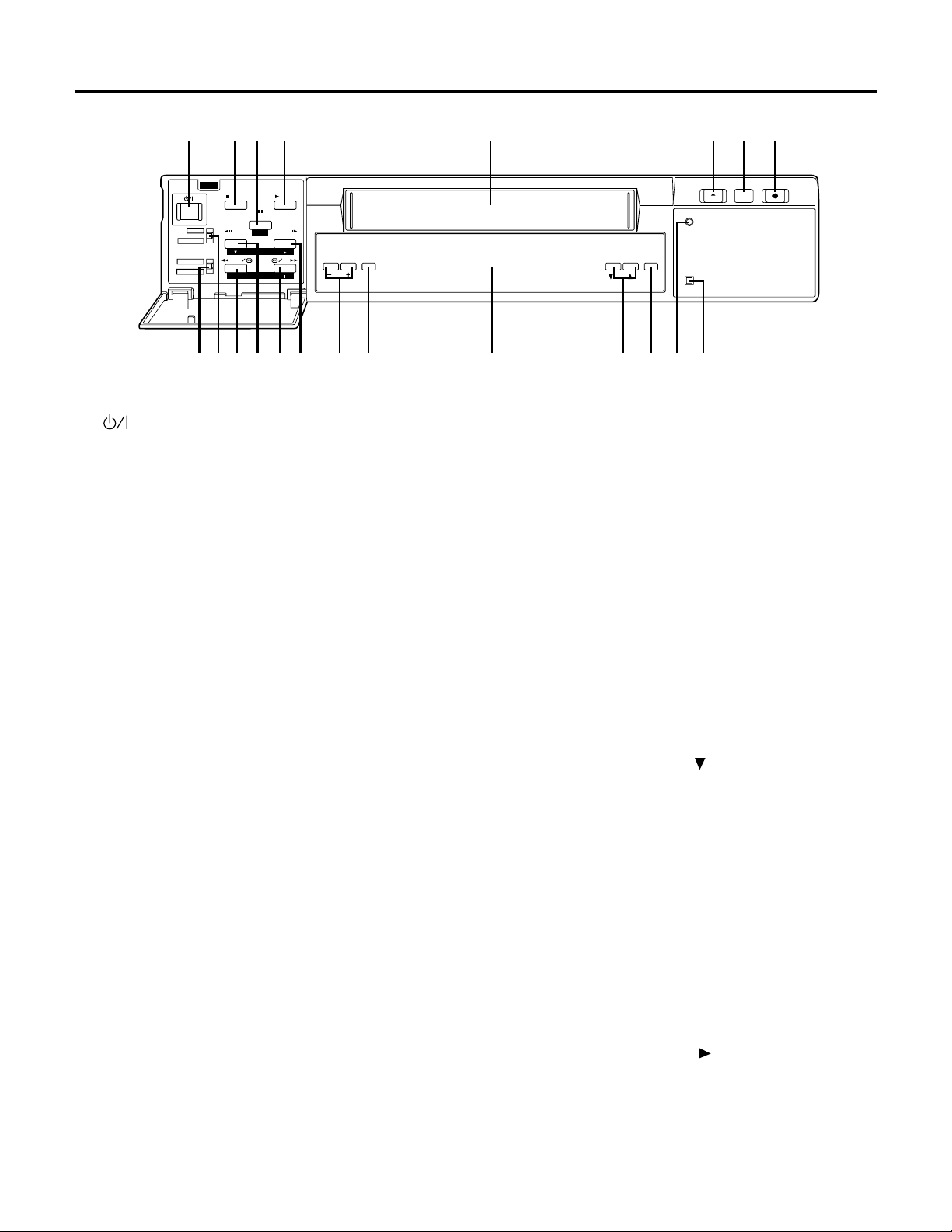
Parts And Their Functions
1234 5 678
STOP PLAY
MENU
OFF
REC LOCK
INT TIMER
OFF
EXT TIMER
1
(STANDBY/ON) switch
The unit is turned on when this switch is pressed.
When the switch is pressed again, the unit is in
standby mode.
2
STOP button
When this is pressed, the tape stops travelling.
3
PAUSE/STILL (PAGE) button
When this is pressed during recording, the tape
temporarily stops travelling.
When pressed during playback, the tape temporarily
stops travelling, and a still picture appears on the TV
monitor. When pressed again, the tape travel
resumes. The pages on the menu screen are
advanced when the button is pressed while a menu
screen is displayed.
4
PLAY button
Playback starts when this button is pressed.
5
Cassette holder
This is the loading slot for the video cassette.
6
EJECT button
This is used to eject the video cassette.
7
REC REVIEW button
When the button is pressed during recording, the
tape runs temporarily in the reverse direction, and
after the recorded section has been played back,
the unit is returned to the recording mode.
8
REC button
Recording starts when this button is pressed.
9
TIMER MODE switch
This is the operation switch for internal timer
recording or external timer recording. The displays
shown below light on the display panel.
INT TIMER:
At the times set by the internal timer,
the power is automatically turned on
or off and recording starts or stops.
OFF:
When timer recording is not performed.
PAUSE/STILL
PAGE
REV ADV
SHIFT
REW FF
SET
FWD ADV
TRACKING /
V-LOCK RESET
EXT TIMER:
0
MENU/REC LOCK switch
When this switch is set to REC LOCK, the time
mode and operation buttons as well as the power
switch cannot be operated while recording is in
progress.
When it is set to MENU, the menu screen appears.
q
REW (SET –) button
When this button is pressed, the tape is rewound.
When it is kept depressed during playback, the
review mode is established.
When it is pressed once during playback in the
alarm search mode, the unit is placed in the review
mode.
When a menu screen is displayed, it is used to
change an item (decrement a value).
w
Field REV ADV (SHIFT ) button
When this is kept depressed during still-picture
playback, the picture is advanced field by field in
the reverse direction. When it is released, the still
picture reappears.
When it is pressed while a menu screen is displayed, the setting items move downward.
e
FF (SET +) button
When this is pressed, the tape is fast forwarded.
When it is kept depressed during playback, the unit
is placed in the cue mode.
When it is pressed once during playback in the alarm
search mode, the unit is placed in the cue mode.
When a menu screen is displayed, it is used to
change an item (increment a value).
r
Field FWD ADV (SHIFT ) button
When this is kept depressed during still-picture
playback, the picture is advanced field by field in
the forward direction. When it is released, the still
picture reappears. When it is pressed while a menu
screen is displayed, the setting items move toward
the right.
EJECT
REC REVIEW
REC
REC
COUNTER /
TIME MODE
SEARCH
ALARM
apoiuyt90qw e r
When the external power is turned
on, recording starts automatically.
6
Page 7

t
Tracking (–, +) buttons/V-LOCK buttons
These buttons are used to adjust the tracking or to
compensate the vertical dancing during still picture.
If noise appears on the playback picture, press the
buttons to adjust the tracking is such a way that the
picture is made as clear as possible. When both
buttons are pressed together during 3- or 6-hour
mode playback, the tracking is adjusted
automatically.
If the image shakes slightly in the vertical direction
during still picture, press the V-LOCK buttons to
reduce the dancing.
Further, the time/date display position can be
adjusted during STOP and EJECT (see page 13).
y
RESET button
When this button is pressed, the counter display is
reset to 0:00:00.
u
Display panel
External timer recording mode display
Cassete insertion display
Recording display
VTR operation
mode display
Operation mode displays
•
Time mode
display
Internal timer recording mode display
Tape remaining display
Memory stop mode display
Alarm search mode display
Auto repeat recording display
Recording lock display
Summer time display
Date setting
display
Time/counter
DisplayOperation mode
Playback
Recording
or
Rec lamp lights.
Still picture
Recording pause
Recording check
Rec lamp lights.
Rec lamp lights.
Fast forwarding
Rewinding
Cue
Review
Forward field advance
Reverse field advance
or (Flashing)
or (Flashing)
Time
display
Error messages
•
An error code appears when trouble has
occurred during operation.
E-2:
Trouble in video cassette insertion area
E-3:
Trouble in video cassette tape loading area
E-4:
Trouble in cylinder area
E-5:
Trouble in tape transport area
d:
Formation of condensation (dew)
i
TIME MODE ( , ) buttons
These buttons are used to select the recording and
playback time mode. Each time this is pressed, the
time mode changes in the following sequence:
3H 6H 12H 24H
o
COUNTER/SEARCH selector button
When this button is pressed, the display on the
display panel changes to time, counter, counter
memory, alarm search and number of repeat
recording times. The M mark appears on the
display panel in the counter memory mode. When
the tape is fast forwarded or rewound in this mode,
the counter will automatically stop when 0:00:00 is
approached. The AS mark appears on the display
panel in the alarm search mode. When the tape is
fast forwarded or rewound in this mode, the unit is
automatically set to still-picture playback at the
alarm recording section. If the FF button or REW
button is pressed during playback with alarm
search, the search will lock. (If this button is
pressed while the tape is being fast forwarded or
rewound, counter memory and alarm search will
not function.)
“** PAS” is displayed during repeat recording.
“__PAS” appears at all other times.
(where “**” denotes the number of repeat times)
p
REC display lamp
This lamp lights while recording is in progress. It
goes off when recording has finished.
a
ALARM display lamp
This remains lighted while alarm recording is in
progress. It flashes when alarm recording ends.
For Swedish and Danish Customers
Aven om denna omkopplare är i “ ”-läge, gar
•
fortfarande en del av apparaten nätspänning.
Selv om denne omskifter er i “ ” stilling, tiløres en
•
del af apparatet stadig strøm.
7
Page 8
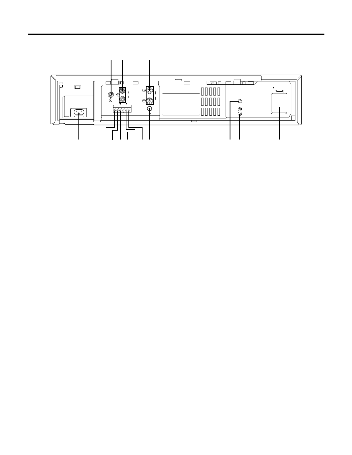
Parts And Their Functions
12
CAMERA
SW OUT
AC IN
4
1
Camera switching output connector
ALARM RESET IN
ALARM IN
67 9
5r
IN
AUDIO
OUT
TAPE END OUT
COMMON
REC IN
80wq
WARNING/
REC OUT
3
Camera switching output connector; connect it to
the frame switcher.
2
Audio input/output connectors
Audio input/output connectors (phono jacks)
3
Video input/output connectors
Video input/output connectors (BNC); connect the
input connector to the video camera, etc. and the
output connector to the TV monitor, etc.
4
AC IN connector
Connect the supplied power cord to an AC outlet.
5
Alarm input connector
Alarm recording input connector; connect it to the
external sensor.
6
COMMON terminal
7
Alarm reset input connector
Input connector for releasing alarm recording; a +4
to +14 V DC voltage is required.
8
REC IN connector
Input connector for recording
VIDEO
BATTERY
IN
OUT
GND
MIC
REMOTE
PUSH OPEN
e
9
Tape end output connector
When the cassette tape comes to its end during
recording, the alarm device installed externally is
activated.
0
WARNING/REC output connector
When trouble has occurred in the unit, the alarm
device installed externally is activated.
Error warning or recording low signal selected on
the menu screen 3 is output.
q
GND Terminal
This terminal is connected to the signal ground
terminal of the connected unit in order to reduce
noise. It is not connected to ground for safety
purposes.
w
MIC input jack
Input jack (3 mm) for an external microphone.
This jack has precedence when signals are
supplied simultaneously to this jack and the audio
input connectors.
e
REMOTE control connector
For connecting the AG-A11 remote controller which
is available as an optional accessory.
r
Battery installation area
Install the battery in this area. See “Lithium Battery”
on page 3.
8
Page 9

Menu Screens
One of the menu screens appears on the TV monitor when the MENU/REC LOCK switch is set to MENU. The
display returns to the regular screen when this switch is set to OFF.
When a menu screen has appeared, the items are set using the page, shift and set buttons.
•
Advance through the pages (page up) of the menu screen using the page button.
•
Move the items (downward or toward the right) using the shift button.
•
Change the items (increment or decrement the values) using the set button.
•
MENU SCREEN 1
[TIME ADJUST] P1
01- 1-2000 SAT
0:00:00
[REC LOCK]
MODE : OFF
[HOUR METER]
00000H
MENU SCREEN 4
[REC MODE] P4
REC T-MODE : OFF
TAPE IN : STOP
TAPE END : STOP
[VIDEO MODE]
MODE : AUTO
DETAIL : ON
MENU SCREEN 2
[DISPLAY] P2
POSITION : L-UPPER
1
2
[REC INDICATE]
NOT REC : CAMERA
3
[BUZZER]
ALARM : OFF
TAPE END : OFF
4
TAPE REMAIN : OFF
ERR WARN : OFF
MENU SCREEN 5
[INTERNAL TIMER REC] P5
w
[TIMER]START END T-M
e
SUN OFF
r
MON OFF
TUE OFF
WED OFF
t
THU OFF
y
FRI OFF
SAT OFF
DLY OFF
MENU SCREEN 3
[ALARM] P3
MODE : OFF
5
DURATION : 30SEC
[RECALL] -
6
-
-
-
7
[OUTPUT SELECT]
TERMINAL OUT : ERR WARN
MENU SCREEN 6
[SUMMER TIME] P6
MODE : OFF
u
[START] [ END ]
WEEK :LST-SUN LST-SUN
MONTH: 3 10
TIME : 2:00 2:00
8
9
0
q
i
o
p
MENU SCREEN 1
In addition to the date and time display and the recording mode lock setting which appear on the TV monitor,
the hour meter is displayed on Menu Screen 1.
Date setting (see page 12)
1
Time setting (see page 12)
2
Recording mode lock
3
ON: LOCK on the front display tube flashes, and all
operations except for REC REVIEW are prohibited
while recording is in progress.
Hour meter
4
This indicates the unit’s total operation time (the
cumulative total for the cylinder rotation time).
9
Page 10

Menu Screens
MENU SCREEN 2
The time/date display position, monitor screen blue display and buzzer settings are performed on Menu Screen 2.
Display position selection
5
This selects the position where the date and time
are to be displayed on the TV monitor.
(L-UPPER ↔ R-UPPER ↔ L-BOTTOM ↔
R-BOTTOM ↔ CENTRE ↔ OFF ↔ L-UPPER...)
Blue display
6
This sets a blue display on the monitor screen at all
times except while recording or playback is in progress.
BLUE: The display on the monitor screen is blue at
all times except while recording or playback is in
progress.
CAMERA: The pictures from the video input
connector are shown on the monitor screen at all
times except while playback is in progress.
Setting of the buzzer sound
7
ALARM: The buzzer sounds once alarm recording is
performed.
TAPE END: When the tape end is reached in the
recording mode, the buzzer sounds while the tape is
at the end.
TAPE REMAIN: The buzzer sounds when there is
only about 3% (with an NV-E180 tape) of the tape
remaining before the end is reached in the recording
mode.
ERR WARN: The buzzer sounds when the unit is set
to the warning status.
To release the buzzer:
ALARM: Release alarm recording.
TAPE END: Transfer the mode from the tape end or
press the STOP button.
TAPE REMAIN: Transfer the mode (but not to
PAUSE or REC REVIEW) from the recording mode
or press the REC button.
ERR WARN: Release the warning status.
When TAPE END or TAPE REMAIN has been set
•
to OFF, the buzzer will not sound; however, the
REMAIN display will remain lit or flashing.
When TAPE END or TAPE REMAIN has been set
•
to ON, REMAIN lights or flashes on the display
tube at the same time as the buzzer sounds.
They cease flashing when the buzzer is released.
Note:
The remaining tape is displayed only with NV-E120
and NV-E180 tapes. It is not displayed when any
other tapes are used.
MENU SCREEN 3
The alarm recording mode and terminal output are set on Menu Screen 3.
Setting of alarm recording and recording time
8
mode during alarm recording (see page 19)
When there is an alarm input during recording in
the time lapse mode, the recording time mode is
switched to the designated mode (3H/6H), and the
details of the alarm status are faithfully recorded.
Alarm recording duration setting
9
This sets the time allowed to elapse from the start
of alarm recording until its end. This time can be
set individually from 30 sec. to 10 min.
(30 SEC → 1 MIN → 2 MIN → 3 MIN → 5 MIN →
10 MIN → CONTINUE → MANUAL)
CONTINUE: Alarm recording continues until the
tape end.
MANUAL: Alarm recording is performed while the
alarm input continues.
Alarm recall (see page 20)
0
This checks the time when an alarm signal was
input (up to 4 times).
Terminal connector output signal setting
q
ERR WARN: When trouble has occurred in the unit
(AUTO OFF), the LOW signal is output.
REC: The LOW signal is output during recording.
10
Page 11

MENU SCREEN 4
Recording mode and video output are selected on Menu Screen 4.
Recording time mode selection
w
When recording starts, the set time mode is always
established.
OFF: The time mode can be set as desired using
the time mode button on the VTR’s sub panel. The
mode can be changed even during recording.
3H: 3-hour mode (compatible with the standard
mode of ordinary VTR’s).
6H: 6-hour mode (compatible with the standard
mode of ordinary VTR’s).
12H: 12-hour mode (linear slow recording)
24H: 24-hour mode (linear slow recording)
Selection of VTR operation when cassette is
e
inserted
STOP: Stop mode
REC: Simply by inserting the cassette tape,
recording is started automatically.
REW REC: When the cassette is inserted, it is
first rewound to the start of the tape and then
recording is started automatically.
MENU SCREEN 5
The internal timer recording modes are set on Menu Screen 5.
Selection of operation when tape end is
r
detected during recording (see page 18)
STOP: Stop mode
REW: The tape is automatically rewound to the
start where it stops.
REPEAT: The tape is automatically rewound to the
start, and recording is repeated.
EJECT: The tape is ejected.
Video signal mode
t
This selects the operation of the colour/black-andwhite automatic selector circuit.
AUTO: The circuit automatically identifies the type
of video input or playback signals, and selects the
colour or black-and-white mode accordingly.
COLOUR: The colour mode is forcibly established.
B_W: The black-and-white mode is forcibly es-
tablished.
Playback picture detail selection
y
The playback picutres can be given a softer look.
OFF: The playback pictures appear softer.
ON: Regular mode
Internal timer recording mode setting (see page
u
16)
This sets the weekly timer or daily timer recording
mode. (OFF/ON)
OFF: Internal timer recording is not set.
ON: Internal timer recording is set.
Note:
Internal timer recording does not operate when the
date and time have not been set.
MENU SCREEN 6
The summer time mode is set on Menu Screen 6.
Selecting the summer time mode
i
Select the summer time mode.
ON: The summer time mode is selected.
OFF: The summer time mode is not selected.
Setting the start time for the summer time mode
o
Set the week, month and hour at which the
summer time mode is to start.
WEEK: Select 1ST, 2ND, 3RD, 4TH or LST (last)
and one of SUN through SAT.
MONTH: Select the starting month (1 – 12).
TIME: Select the start time (1:00 – 22:00)*.
CAUTIONS:
The menu screens are not displayed while the unit is playing back a tape.
•
While the unit is recording, the contents of Menu Screen 1 can be changed; however, Menu Screens 2 to 6 are for
•
reference only and therefore cannot be changed.
Setting the end time for the summer time mode
p
Set the week, month and hour at which the
summer time mode is to end.
WEEK: Select 1ST, 2ND, 3RD, 4TH or LST (last)
and one of SUN through SAT.
MONTH: Select the ending month (1 – 12).
TIME: Select the end time (1:00 – 22:00)*.
* Minutes are for reference only and cannot be adjusted.
11
Page 12

Date and Time Settings
This unit comes with a time/date generator which enables the date and time to be superimposed on the recording.
When the power is switched on, the date, time of the day and time mode are displayed (in the case of a regular
screen).
TV monitor
STOP PLAY
1
Date:
The date appears as day/month/year.
2
Time mode:
This is set by pressing the TIME MODE button. It
flashes unless recording is in progress.
3
Time:
MENU
OFF
REC LOCK
INT TIMER
OFF
EXT TIMER
PAUSE/STILL
PAGE
REV ADV
SHIFT
REW FF
SET
FWD ADV
The 24-hour system is used.
4
Alarm display:
This appears during alarm recording.
Example: Setting the date and time to Saturday, March 3, 2001 at 3:25.
The time mode is set to 24 hours.
1
3
Date
Time
Time mode
2
Alarm display
4
Set the MENU/REC LOCK switch to MENU. Menu
1
Screen 1 appears, and the year digits flash.
Monitor display Display area
[TIME ADJUST] P1
01- 1-2000 SAT
0:00:00
Press the SET (+, –) buttons to set the year to
2
m
“2001”.
[TIME ADJUST] P1
01- 1-2001 MON
0:00:00
When the shift ( ) button is pressed, the month
3
m
digits flash.
Press the SET (+, –) buttons to set the month to
“3”.
[TIME ADJUST] P1
01- 3-2001 THU
0:00:00
m
When the shift ( ) button is pressed, the day digits
4
flash. Press the SET (+, –) buttons to set the day to
“03”.
d
[TIME ADJUST] P1
03- 3-2001 SAT
0:00:00
The year can be set from 2000 to 2079.
•
5
When the shift ( ) button is pressed, the hour
m
d
digits flash. Press the SET (+, –) buttons to set the
d
hour to “3”.
[TIME ADJUST] P1
03- 3-2001 SAT
3:00:00
6
When the shift ( ) button is pressed, minute digits
TIME
flash. Press the SET (+, –) buttons to set the
minutes to “25”.
d
[TIME ADJUST] P1
03- 3-2001 SAT
3:25:00
TIME
12
Page 13

7
When the MENU/REC LOCK switch is set to OFF,
the clock automatically starts running from time
and date set.
03- 3-01 3H
03:25:00
Flashing
For the seconds, “00” is set. Even when the switch
is set to MENU, the time will keep advancing if it
has not been changed.
To clear the date and time display, set POSITION under (DISPLAY) on Menu Screen 2 to OFF.
•
Even if the power should fail for a period of up to one week, the date, time and time mode display (internal
•
timer setting alarm recall) data are stored in the memory (but only if power has been supplied continuously to
the unit for 3 or more days). When the unit has just been purchased or when it has not been used for a long
time, the data is not stored in the memory and the display shown below appears.
[TIME ADJUST] P1
01- 1-2000 SAT
0:00:00
For the date setting, the unit automatically adjusts for leap years.
•
Due to temperature fluctuations and other factors, the clock time may run fast or slow with a monthly error of
•
up to ±60 seconds. This is not indicative of malfunctioning. Reset the time at regular intervals.
When the time is reset to “0:00:00” as described, check the menu settings. If any of the settings are incorrect,
•
please set them again.
All the internal timer settings are set to OFF,
and the alarm recall display is cleared.
TIME
Time/Date Display Position
The position of the date and time displays on the TV monitor changes as shown below when (DISPLAY) on Menu
Screen 2 is changed.
Top left corner Top right corner Bottom left corner No displayCentreBottom right corner
1
Set the MENU/REC LOCK switch to MENU to
display to menu screens. Press the page button to
display Menu Screen 2 on the TV monitor.
POSITION : L-UPPER
2
Press the set (+, –) buttons to position the display
as desired.
POSITION : L-BOTTOM
3
Upon completion of the settings, set the MENU/
REC LOCK switch to OFF. The regular screen is
restored, and the date and time appear at the
selected position.
TIME/DATE display position adjustment function
When the unit is in STOP or EJECT mode, the position
of the displayed time/date can be adjusted by pressing
the TRACKING (–) or TRACKING (+) button.
Pressing the TRACKING (–) button moves the
•
position vertically. (Pressing the button 3 times will
return the display to its original position.)
Pressing the TRACKING (+) button moves the
•
position horizontally. (Pressing the button 3 times
will return the display to its original position.)
Pressing the (–) and (+) buttons simultaneously will
•
return the display to its original position (factory
setting).
13
Page 14

Time Mode Selection
EJECT
REC REVIEW
COUNTER /
SEARCH
REC
ALARM
PULL OPEN
TRACKING /
V-LOCK RESET
TIME MODE
TIME MODE button
Refer to the table given below to select the mode that suits the intended purpose of use.
REC
Tape
replacement
standard
(recording
times)
Video
recording
interval
(in seconds)
1/50
Audio
recording
Possible
Type of
tape travel
Continuous travel
Mode
3H
Recording enable time
(in hours)
180-minute
tape
3
120-minute
tape
2
Continuous travelPossible6H 6 4 1/50
12H
24H
12
24
16
8
50
50
0.1
0.18
Possible
Possible
Continuous travel
at low speed
Continuous travel
at low speed
Notes on operation
This unit is designed with the NV-E180 cassette tape as a reference.
•
Depending on the type of video cassette used, the recordable time will differ.
•
The actual recording enable time will be slightly longer than the “Recording enable time” given in the above
•
table although this will depend on the tape used.
For instance, it is possible to record for about 27 hours using a 180-minute tape in the 24H mode.
The 12- and 24-hour modes are time lapse modes. Pictures are recorded with frames skipped to enable
•
lengthy recording and playback.
A tape recorded in a time lapse (12-/24-hour) mode can be played back in quick motion in the 3-hour mode.
•
A tape recorded in the 3-hour mode can be played back in slow motion using the time lapse (12-/24-hour)
•
mode.
A tape recorded in the 6-hour (or 3-hour) mode cannot be played back in the 3-hour (or 6-hour) mode.
•
When a tape recorded on the 6-hour mode is played back in another mode, colour programme is played back
•
in black and white, but this is not a malfunction.
(With still picture, field FWD ADV and field REV ADV operations, the colours at the top of the screen may
disappear at some tracking positions, but this is not a malfunction.)
Tapes recorded on this machine cannot be played back other VHS video recorder as they are not compatible.
•
Selecting the cassette tape
The unit is designed as a product required to exhibit high reliability in surveillance, security, monitoring, etc. In
•
order to maintain its recording reliability, it is recommended that the Panasonic video tapes listed below be used.
<VHS tapes>
NV-E180
•
NV-E120
•
NV-E90
•
NV-E60
•
Avoid using 240-minute tapes with this unit.
•
14
Page 15

Recording Procedure
1
Switch on the power to the connected equipment.
2
Adjust so that the images of the video cameras
appear properly on the TV monitor.
3
Check that the date and time displayed on the TV
monitor have been adjusted properly.
4
Insert a cassette tape into the unit after checking
that the tab on the cassette is intact.
Notes on operation
If the PAUSE/STILL button is pressed during recording, the unit is set to the pause mode, and after about 5
•
minutes in this mode it is transferred to the stop mode.
Neat frame-to-frame continuity is not achieved if the recording mode is set again after the PAUSE/STILL button
•
is pressed during recording.
When the MENU/REC LOCK switch has been set to OFF, other operations can be performed during recording.
•
When restoration-of-power-after-failure recording is performed,recording can be continued in the same time mode
•
even if the power should fail provided that the power is restored within about one week. (This applies only if
the power has been supplied continuously for 3 or more days.)
When performing auto repeat recording or timer recording, do not neglect to conduct the routine inspections.
•
When recording images from a black-and-white camera, set the video signal mode on Menu Screen 4 to B_W.
•
Remove the cassette tape if the unit is to be left standing for a prolonged period of time.
•
When the power supply is interrupted during recording (with the switch still ON), a non-recorded portion will
•
be made in the beginning of the tape travel, or the tape will be over-recorded at its ending section. This is not
a malfunction.
5
Set the timer recording, auto repeat recording, alarm
recording, restoration-of-power-after-failure recording or other recording function.
6
Select the time mode for the recording.
7
Press the REC button.
Tips For Better Recording
In order to ensure greater reliability in monitoring, surveillance and other continuous operations lasting many hours,
this unit comes with some safety functions for recording. Read the following descriptions of these functions before
proceeding to operate the unit.
Recording mode lock
There are two ways, as described below, to maintain
the recording mode during recording by disabling the
operations of the switch as well as the TIME MODE
and operation buttons.
1
Set the MENU/REC LOCK switch to REC LOCK.
2
Set REC LOCK on Menu Screen 1 to ON. (See
Note)
The following button and connectors are operational
during recording even if the unit is set to REC LOCK.
Alarm input connector, alarm reset connector
•
REC REVIEW
•
Recording check
When the REC REVIEW button is pressed during
recording, the tape runs temporarily in the reverse
direction, and the recorded section is played back. This
function can be used to check the daily operation of the
equipment in the system.
Restoration-of-power-after-failure
recording
When a power failure has occurred during recording,
the unit automatically starts recording if the power is
restored within approximately one week.
•
When the power fails, the tape “loss” safety protection function is activated to protect the video heads
and video tape.
Before power is restored After power is restored
Stop, play, fast forward Stop mode is established.
•
Recording mode is
established.
Unit is returned to the mode
applying before the power
failed.
15
Recording
•
Auto rewind
•
Auto rewind during auto
•
repeat recording
Notes:
When the power cord has come out of the socket or
•
a power failure has occurred, no operations will be
acknowledged for about 30 seconds after the power
has been restored: this is to protect the tape.
Once the recording mode is established, recording
•
cannot be released until REC LOCK on Menu Screen
1 is set OFF.
Page 16

Timer Recording
There are two methods of timer recording: one uses the internal timer and the other uses an external timer.
Internal timer recording
Start time and stop time
Bear in mind the following points when setting these
times.
When the stop time is set later than the start time:
•
Recording will commence at the start time on the
day concerned and stop at the end time on the same
day.
Example: 8:30 → 17:00
When the start time is set later than the stop
•
time or the start time and stop time for weekly
recording (weekly timer) are the same:
Recording starts at the start time on the day
concerned and ends at the stop time on the following day.
Example: 17:00 → 8:30
When the start time and stop time are the same
•
(for weekly recording):
Recording starts at 8:30 on the day concerned and
ends at 8:30 on the following day.
Example: 8:30 → 8:30
To record for an entire day, set the start time and
stop time to 0:00.
Notes:
Weekly recording (weekly timer) can be set by the
•
day of the week.
When (INTERNAL TIMER REC) on Menu Screen 5
•
is set to OFF for both the weekly timer and daily
recording (daily timer), nothing appears for the start
or stop time. Timer recording is considered not to
be set.
VTR operations after the settings
The unit is in STANDBY mode, and even if other
•
buttons are pressed, their operations are not
accepted.
When the start time and stop time have not been
•
set, INT flashes on the display.
Alarm recording is performed in the event of an
•
alarm input even when the unit is in the timer
recording standby mode. When alarm recording is
completed, the unit is set to the timer recording
standby mode.
Even when the power should fail, the start and stop
•
times set for timer recording are stored in the
memory provided that the power is restored within a
week or so (but only if power has been supplied
continuously to the unit for 3 or more days).
When the unit has just been purchased or when it
•
has not been used for a long time, the start and stop
times are not stored in the memory.
Releasing the internal timer mode
Set the TIMER MODE switch to OFF to clear INT on
the display.
Note:
Since it takes some moments for recording to start,
•
set the start time for timer recording one minute
earlier.
Internal timer recording operation
1
Check that a video cassette with its tab intact has
been inserted.
2
Check that the TV monitor shows the correct
present time.
3
Set the MENU/REC LOCK switch to MENU to
display the menu screens. Press the page button so
that the INTERNAL TIMER REC timer setting
screen appears on the TV monitor.
[INTERNAL TIMER REC] P5
[TIMER]START END T-M
SUN OFF
MON OFF
TUE OFF
WED OFF
THU OFF
FRI OFF
SAT OFF
DLY OFF
16
4
Set the operation times of the internal timer.
For details on the settings, refer to the sections
•
on “Daily timer” or “Weekly timer.” (See page
17.)
5
Upon completion of the settings, set the MENU/
REC LOCK switch to OFF. The regular screen is
restored.
6
Set the TIMER MODE switch to INT TIMER so that
INT lights on the display.
When the time and date for Menu Screen 1 have
not been set, a cassette has not been inserted, the
timer has not been set, or when a cassette with a
broken out tab has been inserted, the buzzer
sounds and INT flashes on the display.
Page 17

Daily Recording (Daily Timer)/Weekly Recording (Weekly Timer)
Example: When recording from 8:30 to 12:00 from
Sunday through Thursday and from 9:00 to 12:00 on
Fridays and Saturdays
1
Check that OFF or ON for Sunday (SUN) is
flashing. If the setting is OFF, press the set (+, –)
buttons to display ON.
[INTERNAL TIMER REC] P5
[TIMER]START END T-M
SUN OFF
MON OFF
2
When the shift ( ) button is pressed, the setting
moves to the start time and the “hour” digits flash.
SUN ON 0:00 0:00
3
Press the set (+, –) buttons to display “8.”
SUN ON 8:00 0:00
4
When the shift ( ) button is pressed, the “minutes”
digits flash.
SUN ON 8:00 0:00
5
Press the set (+, –) buttons to display “30.”
SUN ON 8:30 0:00
6
When the shift ( ) button is pressed, the “hour”
digits flash.
SUN ON 8:30 0:00
7
Press the set (+, –) buttons to display “12. ”
SUN ON 8:30 12:00
8
When the shift ( ) button is pressed, the “minutes”
digits flash.
SUN ON 8:30 12:00
9
Press the set (+, –) buttons to display “00.”
SUN ON 8:30 12:00
0
Press the shift ( ) button and set the recording
time mode. When the shift ( ) button is pressed,
the MON is flashing.
SUN ON 8:30 12:00 24
q
Following the same procedure in steps 1 to 10,
display the start time of “8:30” and stop time of
“12:00” from Monday (MON) through Thursday
(THU). Following the above procedure, set the
times for Friday (FRI) and Saturday (SAT) as well.
In this way, the timer operation times have been
set for each day of the week.
The settings for daily recording (daily timer) are
also performed following the same steps 1 to 10.
The setting shown on the screen at the left translates into the weekly and daily timer recording combinations
•
shown below which, in turn, means that the actual recording time on the tape is shown at the bottom.
[INTERNAL TIMER REC] P5
[TIMER]START END T-M
SUN ON 8:30 8:00 24
MON ON 12:00 14:00 12
TUE OFF
WED OFF
THU ON 14:00 23:00 12
FRI OFF
SAT ON 12:00 8:00 24
DLY ON 18:00 8:00 12
The day of the week time settings are displayed, enabling the settings to be checked for each day of the week.
•
Proceed with the setting due consideration given to the total recording time since a 180-minute tape is long enough
•
Weekly
Timer
Daily
Timer
Actual
Recording
Time
Sunday Monday Tuesday Wednesday Thursday Friday Saturday
24H
24H
8:00 8:00
8:30
8:00 8:00
18:00
24H 12H12H 12H 12H 12H
8:00 8:30
12H 12H 24H
14:00
12:00
12H12H
12H
24H 24H
8:00
12:00
14:00
8:00 18:00 8:00 18:00 8:00
18:00
14:00 23:00 12:00
14:00 8:00
18:00 8:00 12:00
to provide recording for up to 24 hours only.
17
Page 18

Timer Recording
External Timer Recording
The unit can be made to record using an external timer to turn on its power.
REC REVIEW
REC
Power Cord
(supplied)
To AC IN
(Audio timer available from dealer)
Timer
AG-TL350
EJECT
PULL OPEN
TRACKING /
V-LOCK RESET
REC
COUNTER /
TIME MODE
SEARCH
ALARM
External timer recording operations
1
Check that a video cassette with its tab intact has
been inserted.
If the video cassette tape has not been inserted or if its accidental erasure prevention tab has been broken,
•
EXT will flash on the display, and external timer recording cannot be conducted.
Since it takes some moments for recording to start, set the start time for timer recording one minute earlier.
•
Depending on the tape position, some of the images at the start of the external timer recording may not be
•
recorded or may record over the images at the end of the previous external timer recording.
2
Set the TIMER MODE (REC MODE) switch to EXT
TIMER so that EXT lights on the display. At the set
time, power is supplied from the external timer and
the unit is set to the recording mode.
Auto Repeat Recording/Auto Rewinding
Auto repeat recording:
Auto rewinding:
This function automatically rewinds the tape to the start when the tape end is detected in the
recording mode.
This function automatically rewinds the cassette tape when its end is detected in the
recording mode, and it repeats recording from the start of the tape.
1
Check that a video cassette with its tab intact has
been inserted.
3
Press the shift ( ) button to move the flashing to
TAPE END. Press the set (+ or –) button to display
REPEAT for auto repeat recording or REW for auto
2
Set the MENU/REC LOCK switch to MENU to
display the menu screens. Press the page button
rewinding.
TAPE END : REPEAT
to display Menu Screen 4 on the TV monitor.
4
“R” lights on the display.
If auto rewinding has been selected, “R” is
[REC MODE] P4
REC T-MODE : OFF
TAPE IN : STOP
TAPE END : STOP
•
cleared.
5
Upon completion of the settings, set the MENU/
REC LOCK switch to OFF. The regular screen is
[VIDEO MODE]
MODE : AUTO
DETAIL : ON
restored.
Notes of operation
When auto repeat recording is to be performed, do not neglect the routine inspections. Since the image
•
deteriorates when the same tape is used over and over again for auto repeat recording, replace the tape with a
new one after about 50 recordings.
Alarm signals are not accepted during auto rewinding, and so alarm recording is not performed.
•
If an alarm signal is supplied during auto repeat recording, the alarm recording mode is established. If the tape
•
then reaches its end, auto repeat recording is performed but alarm recording is released.
When the power cord has come out of the socket or a power failure has occurred, no operations will be acknowl-
•
edged for about 30 seconds after the power has been restored: this is to protect the tape.
18
Page 19

Alarm Recording (Emergency Recording)
When an emergency occurs at the monitoring site during prolonged monitoring and recording, the alarm function
is automatically triggered, and alarm recording is performed.
Principle of alarm recording Connecting the alarm input
Alarm input Alarm reset input
connector
Tape start
Tape end
Recording Alarm recording Recording
Time lapse mode Alarm mode
Time lapse mode
(3H/6H)
When an alarm signal is supplied by an alarm sensor
•
(door or intercom switch, etc.) during recording in a
time lapse mode, the recording speed is switched to
the 3- or 6-hour mode and the details of the state of
emergency are faithfully recorded.
Alarm and display methods during
alarm recording
EJECT
REC REVIEW
REC
TIME MODE
COUNTER /
SEARCH
REC
ALARM
PULL OPEN
TRACKING /
V-LOCK RESET
ALARM display lamp
When an alarm signal is supplied, the alarm display
•
lamp functions as follows.
Alarm switch
CAMERA
AC IN
SW OUT
ALARM RESET IN
ALARM IN
COMMON
REC IN
IN
AUDIO
OUT
TAPE END OUT
Alarm switch
Alarm reset switch
4 V – 14 V
Alarm recording starts when the alarm switch is set
•
on. When the alarm reset switch is set ON after
recording has started, alarm recording is released
and operation is returned to the original time lapse
recording mode.
Alarm recording can be released by pressing the
•
STOP button during alarm recording.
However, it cannot be released even by pressing the
STOP button if the MENU/REC LOCK switch is at
REC LOCK or INT is lighted on the display.
WARNING/
REC OUT
Alarm
lamp
Alarm input Alarm reset
input
17-11-00 3H
10:14:30 A
TV monitor
OffFlashingOn
switch is
pressed.
Display
switch to
“3H” or “6H.”
“A” display
appears
19
Alarm recording can be automatically reset without
•
supplying the alarm reset input signal.
The reset time can be set for 30 sec., 1.0, 2.0, 3.0,
5.0 or 10 minutes.
Another option is alarm recording only while the alarm
•
input signal is supplied.
Alarm recording is also possible as far as the end
•
of the tape.
Page 20

Alarm Recording (Emergency Recording)
Alarm recording operation
1
Check that a video cassette with its tab intact has
been inserted.
2
Set the MENU/REC LOCK switch to MENU to
display the menu screens. Press the page button
to display the alarm recording setting screen (Menu
Screen 3) on the TV monitor.
[ALARM] P3
MODE : OFF
DURATION : 30SEC
[RECALL] -
-
-
3
Press the set (+ or –) button to display 3H or 6H for
MODE.
MODE 3H
If TAPE END on Menu Screen 4 has been set to REPEAT, the auto repeat recording mode is established when
•
the tape comes to the end.
With emergency recording, set the unit to the STANDBY or STOP mode.
•
4
Press the shift ( ) button to move the flashing to
DURATION.
Press the set (+ or –) button to set the recording
duration.
5
Upon completion of the settings, set the MENU/
REC LOCK switch to OFF. The regular screen is
restored.
6
Press the REC button.
If an alarm input signal is subsequently supplied,
the time mode set by T-MODE changes to 3H or
6H, and alarm recording continues until the alarm
is released.
Alarm Recall
The time when the alarm signal was input can be ascertained on the TV monitor by checking the alarm input
time in the RECALL item on Menu Screen 3.
1
Set the MENU/REC LOCK switch to MENU to
display the menu screens. Press the page button
to display the alarm recording setting screen (Menu
Screen 3) on the TV monitor.
[ALARM] P3
MODE : ALARM
DURATION : 30SEC
[RECALL] 10-10-01 20:19
14- 9-01 12:05
30- 8-01 08:40
25- 6-01 04:14
[OUTPUT SELECT]
TERMINAL OUT : ERR WARN
The alarm recall function stores up to 4 alarm input times in the memory and displays them on the screen. If
•
there have been more than 4 inputs, they will be deleted from the screen in sequence starting with the oldest
data.
When the RESET button is pressed while Menu Screen 3 is on the display, the alarm recall memory can be
•
cleared.
2
Upon completion of the settings, set the MENU/
REC LOCK switch to OFF. The regular screen is
restored.
20
Page 21

Playback Procedure
Before operating the unit, check that the internal/external timer recording displays (INT/EXT) have been cleared
from the display. (If INT or EXT is displayed, set the TIMER MODE switch to OFF to clear it.)
1
Switch on the power to the unit and TV monitor.
2
Insert the recorded cassette tape into the unit.
3
Select the time mode.
4
Press the PLAY button.
Notes on operation
1.
Bear in mind the following points when playing back parts of a tape recorded in a time lapse (12-/24-hour) mode.
When the tape is played back in the same mode, noise resembling dropouts will appear on the screen: this
•
is not indicative of malfunctioning.
The picture may oscillate in the vertical direction: this is not indicative of malfunctioning.
•
When a tape is played back in the same time mode, the picture may shake slightly sideways: this is not
•
indicative of malfunctioning.
Turn Quasi-V insertion ON ( ) or OFF ( ) with the FWD ADV button. Dancing can be minimized when a
•
tape is played back in a time lapse (except 3- or 6-hour) or linear slow mode. Moreover, playing back a tape in
a system featuring a frame switcher enables the appearance of the pictures of other cameras to be reduced.
2.
Bear in mind the following points when playing back parts of a tape recorded in a VHS mode (3 or 6 hours).
When a tape is played back in a time lapse mode, slight noise may appear at the top and bottom of the
•
screen: this is not indicative of malfunctioning.
When the tape is played back in the 12H or 24H mode, the picture may oscillate in the vertical direction: this is
•
not indicative of malfunction.
When a tape recorded on the 6-hour mode is played back in another mode, colour programme is played back
•
in black and white, but this is not a malfunction.
3.
When noise has occurred during still-picture playback, press the FWD ADV button to play it out. (It may not
always be possible to play out the noise.)
4.
Bear in mind that if the power cable is disconnected and then re-connected or if the power has been restored
after it has failed when the tape was played with EXT indicated on the display by the TIMER MODE switch,
the unit will automatically be set from playback to the recording mode.
5.
When the PAUSE/STILL button is pressed during playback, the unit is set to the pause mode, and a still picture
will appear on the monitor screen. To release this state, press the PAUSE/STILL button again or press the
PLAY button. If the unit is kept in the pause mode for more than 5 minutes, it will be set to the stop mode.
6.
If the horizontal AFC on the TV monitor is too long or when a video camera with random interlace scanning
has been used, the top area of the TV monitor may be distorted: this is not indicative of malfunctioning.
7.
Tapes recorded on this machine cannot be played back other VHS video recorder as they are not compatible.
8.
When the power cord has come out of the socket or a power failure has occurred during fast forwarding or
rewinding, no operations will be acknowledged for about 30 seconds after the power has been restored: this is
to protect the tape.
Tracking
When noise such as that shown below appears on the
playback image in the 3- or 6-hour time mode, press
the tracking (+ or –) button to minimize the noise.
TRACKING /
V-LOCK
For the tracking default setting, press the “+” and “–”
•
buttons together (in the 3- or 6-hour time mode
only).
In the 12- or 24-hour mode, press the “+” or “–”
•
button to adjust the tracking.
Vertical hold adjustment
If the image shakes slightly in the vertical direction during
still-picture playback, press the V-LOCK buttons (–, +) to
reduce the dancing.
EJECT
TIME MODE
COUNTER /
SEARCH
REC
ALARM
21
PULL OPEN
TIME
LAPSE
If the TV monitor has a vertical hold control, adjust
•
TRACKING /
V-LOCK RESET
that control also.
REC REVIEW
REC
Page 22

Routine & Regular Inspection Request
This unit is designed to withstand many hours of operation. Nevertheless, it is recommended that routine inspections
be conducted to help ensure trouble-free operation.
CAUTION
Do not forget to conduct the routine inspection with auto repeat recording.
Routine inspection procedure
1
Set the power switches on the unit, video cameras,
TV monitor and other equipment connected in the
monitoring system to the ON position.
2
Is the picture on the TV monitor OK?
3
Are the date and time displayed on the TV monitor
correct?
4
Press the REC REVIEW button during the recording and check that the image are being recorded
correctly.
Action taken after routine inspections
In the unlikely event of a problem with the unit, turn the unit to STANDBY mode, take hold of the power plug and
disconnect it from the power outlet, and consult with the dealer from whom the unit was purchased.
Regular inspections recommended
This unit has an hour meter which shows for how many hours the VTR has been used. When the MENU/REC
LOCK switch is set to MENU, Menu Screen 1 appears on the TV monitor, and the hour meter can be checked.
Use the hour meter as a rough guideline to cleaning or replacing the parts inside the unit. The regular screen is
restored when the MENU/REC LOCK switch is set to OFF. For further details, consult with your dealer.
MENU
OFF
REC LOCK
[HOUR METER]
00000H
TV monitor
22
Page 23

Troubleshooting
Trouble with installation
No power.
No picture.
Indistinct picture.
Is the power plug inserted properly into the AC outlet?
•
Is the unit connected properly with the TV, video cameras, etc.?
•
Are any of the connecting cables making faulty contact?
•
Has the focus on the video cameras been adjusted correctly?
•
Trouble with functions or operation
Nothing happens even when operation
buttons are pressed.
“ ” mark is flashing. The unit will not operate because its safety protection function
In case of moisture
detection:
The “ ” mark at display
section flashes.
Date and time display data has not been
stored in memory when the power failed.
Is the video cassette loaded?
•
Is the MENU/REC LOCK switch at OFF?
•
Has the video cassette been inserted properly? Press the
•
EJECT button to eject the cassette and insert properly.
Has INT lighted on the display?
•
•
has been triggered. Wait until the flashing disappears.
Ejection will remain
incomplete when a video
cassette has been inserted.
Has the unit’s power plug been disconnected from the power
•
outlet for a long time?
Insert the unit’s power plug into the power outlet and supply
power continuously for at least 3 days to the unit.
Wait until the “ ” mark
goes out with switch
turned “ON”. It may take a
few hours, although it
depends upon conditions.
Trouble with recording
Tape can be played, fast forwarded or
rewound but not recording results.
Recording has stopped. Is the video cassette tape at its end?
The power has been restored after a
power failure but recording does not
automatically resume.
Recording cannot be stopped.
1-week programmed timer recording
cannot be conducted properly.
One or more cameras do not record
when a multiple number of cameras are
used.
No auto repeat recording. Has the stop button been pressed during auto rewinding?
Is the tab on the video cassette broken?
•
•
Have more than 5 minutes elapsed since the PAUSE/STILL
•
button was pressed during recording?
Are the routine inspections being carried out? If this phenome-
•
non keeps recurring, it means that some failure or other is to
blame. Consult with your dealer.
Has the power failure lasted a long time (more than 1 week)?
•
Set the timer recording switch to EXT to ensure that the unit is
set to the recording mode even after a prolonged power failure.
First set the MENU/REC LOCK switch to OFF and then
•
operate.
Is REC LOCK on Menu Screen 1 at OFF?
•
Are the date and time on the regular displays correct?
•
(See page 12)
Turn the time adjustment control on the frame switcher, and adjust
•
it to a setting which is longer than the video recording duration in
the recording time mode.
Connect a camera switching cable between the unit and frame
•
switcher.
•
23
Page 24

Troubleshooting
No timer recording. Are the present time and start/stop times for the timer
•
recording correct?
Has INT or EXT lighted on the display?
•
No alarm recording. Have the alarm sensors and alarm input connectors been
•
connected properly?
Has the alarm recording mode been selected on Menu Screen
•
3?
Trouble with playback
Noise sometimes appears on the playback pictures.
Dirty playback picture. The video heads may be dirty or clogged or they may have
“Snow” on playback picture. The video heads may be dirty or clogged. Consult with your
While a multiple number of cameras are
being used, two scenes appear as the
playback picture when the cameras are
switched.
Recording starts when the unit’s power
plug is connected to or disconnected
from the power outlet.
No playback because recording starts
when the main power for the connected
equipment is set to ON.
Adjust the tracking buttons. (See page 21)
•
•
reached the end of their service life. Consult with your dealer.
•
dealer.
Has the camera switching signal cable been connected
•
properly?
Has INT or EXT lighted on the display?
•
Has INT or EXT lighted on the display?
•
Input/Output Terminal Signal Level
Terminal Signal Level Note
Alarm Input/REC IN
Alarm Reset Input
Camera Switching Output
During auto repeat or
auto rewinding
Tape end output
Approx. 10 sec
Warning output
MIN 400 msec.
MIN 400 msec.
Video recording interval
20 msec.
VOH
VOL VOL
11 – 13 V
VOH:
VIL: 0 – 0.6 V
4 – 14 V
VIH:
When stopped
OL
V
VIH:
11 – 13 V
LOW Input
HIGH Input
VOH = 11 – 13 V (5.6 kΩ)
VOL = 0 – 0.6 V (max. 3 mA)
VOH = 11 – 13 V (4.7 kΩ)
VOL = 0 – 0.6 V (max. 3 mA)
VOH = 11 – 13 V (4.7 kΩ)
VOL = 0 – 0.6 V (max. 3 mA)
24
Page 25

Specifications
Power Source:
Power Consumption:
General
Operating
Temperature:
Operating
Humidity:
Dimensions:
Weight:
Video Recording/
Playback
System:
Tape Speed:
Tape Format:
Recording Time:
FF/REW Time:
Video
Television
System:
Modulation
System:
Video Input
(BNC):
Video Output
(BNC):
S/N:
220 – 240 V AC, 50 – 60 Hz
20 W
5°C to 40°C
35% to 80%
430 (W) × 88 (H) × 293.5 (D) mm
Approx. 3.7 kg
4 rotary heads, Azimuth recording
system, VHS format
23.39 mm/s (3H mode)
VHS tape
3 hours (with 180-minute tape/3H
mode)
Less than 2 min. (with 180-minute
tape)
CCIR Standard (625 lines, 50 fields)
PAL colour signal
Luminance; Frequency modulation
recording
Colour signal; Converted subcarrier
phase shift recording
1.0 Vp-p, 75 ohms
1.0 Vp-p, 75 ohms, unbalanced
B/W mode; 45 dB (3H mode, Detail
OFF)
Colour mode; 45 dB (3H mode,
Detail OFF)
Audio
Line Input
(Phono):
Mic Input (3 mm):
Line Output
(Phono):
Track:
Recording/
Playback
mode:
–10 dBV, 47 kohms
–60 dBV, 600 ohms
–8 dBV, 1 kohm
1 track (normal)
3H/6H/12H/24H mode
Connectors
Alarm Input/
REC IN:
Alarm Reset
Input:
Short circuit
+4 V – +14 V
Standard accessory
Power Cord:
Weight and dimensions shown are approximate.
Specifications are subject to change without notice.
× 1
25
Page 26

Matsushita Electric Industrial Co., Ltd.
Central P.O. Box 288, Osaka 530-8691, Japan
Printed in Japan
VQT8975
S1000H100Î
B
E
 Loading...