

Page 1
Operating Instructions
Remote Control Panel
Model No.
AG- P
Car Use only
Before operating this product, please read the instructions carefully and save
this manual for future use.
S0806K1116-M
D
ENGLISH
VQT1A20-1
Page 2
Read this first!
WARNING:
• TO REDUCE THE RISK OF FIRE OR SHOCK HAZARD, DO NOT
EXPOSE THIS EQUIPMENT TO RAIN OR MOISTURE.
• TO REDUCE THE RISK OF FIRE OR SHOCK HAZARD, KEEP THIS
EQUIPMENT AWAY FROM ALL LIQUIDS. USE AND STORE ONLY
IN LOCATIONS WHICH ARE NOT EXPOSED TO THE RISK OF
DRIPPING OR SPLASHING LIQUIDS, AND DO NOT PLACE ANY
LIQUID CONTAINERS ON TOP OF THE EQUIPMENT.
CAUTION:
TO REDUCE THE RISK OF FIRE OR SHOCK HAZARD AND
ANNOYING INTERFERENCE, USE THE RECOMMENDED
ACCESSORIES ONLY.
indicates safety information.
2
Page 3

Read this first!
(continued)
CAUTION:
In order to maintain adequate ventilation, do not install or place this
unit in a book case, built-in cabinet or any other confined space.
To prevent risk of electric shock or fire hazard due to overheating,
ensure that curtains and any other materials do not obstruct the
ventilation.
FCC Note:
This equipment has been tested and found to comply with the limits
for a class A digital device, pursuant to Part 15 of the FCC Rules.
These limits are designed to provide reasonable protection against
harmful interference when the equipment is operated in a commercial
environment. This equipment generates, uses, and can radiate radio
frequency energy, and if not installed and used in accordance with
the instruction manual, may cause harmful interference to radio
communications. Operation of this equipment in a residential area
is likely to cause harmful interference in which case the user will be
required to correct the interference at his own expense.
Warning: To assure continued FCC emission limit compliance, the user
must only use shielded interface cables when connecting to external
units. Also, any unauthorized changes or modifications to this equipment
could void the user’s authority to operate it.
•
This Remote Control Panel is designed for use and installation in a vehicle.
For example, it may be mounted on the dashboard or alongside the seat.
• The installation of this equipment must only be performed by a
professional installer.
indicates safety information.
3
Page 4

IMPORTANT SAFETY INSTRUCTIONS
(1) Read these instructions.
(2) Keep these instructions.
(3) Heed all warnings.
(4) Follow all instructions.
(5) Do not use this equipment near water.
(6) Clean only with a dry cloth.
(7) Do not block any ventilation openings. Install in accordance with the
manufacturer’s instructions.
(8) Do not install near any heat sources such as radiators, heat registers, stoves,
or any other equipment (including amplifiers) that produce heat.
(9) Only use attachments/accessories specified by the manufacturer, and as
outlined in this manual.
(10) Refer all servicing requests to qualified service personnel. Servicing is
required when the equipment has been damaged in any way, such as
damage to the power supply cord or plug, liquid being spilled on or objects
have fallen into the equipment, the equipment has been exposed to rain or
moisture and does not operate normally, or has been dropped.
4
Page 5

Contents
Before use
Read this first! …………………… 2
IMPORTANT SAFETY INSTRUCTIONS
Features/Included Accessories … 6
About This Manual ………………… 7
Before Use ………………………… 7
How to Operate
Turning the Remote Control Panel On and Off
Basic Menu Operations ………… 14
Setting up/Deleting Officer Data
Locking and Unlocking Buttons
Viewing Live Video ……………… 19
Selecting a camera ……………… 19
Zooming …………………………… 19
Making a backlit image easier to view
Making a dark image easier to view
To mute AUDIO2 input sound
Turning off the LCD panel ……… 19
Adjusting image brightness …… 20
Adjusting image focus ………… 20
To turn off the [REC] lamp during
recording ………………………… 20
Selecting AUDIO2 input ………… 21
Checking audio ………………… 21
Viewing Memory Card Video
Recorder status ………………… 21
13
…16
…18
19
19
…… 19
Operating Precautions …………… 8
Control Reference Guide ………… 9
4
Front panel………………………… 9
Rear panel ………………………… 11
Connections ……………………… 12
Recording …………………………… 23
Starting and stopping recording
A trial shoot ……………………… 24
Starting and stopping intermittent
recording ………………………… 24
Playback …………………………… 24
Playback …………………………… 24
Changing playback method …… 25
Adding bookmarks ……………… 26
Selecting a file for playback …… 27
Turning Audio1 and 2 ON and OFF
Viewing Memory Card Video
Recorder status
Restoring Files …………………… 29
Displaying Product Information … 30
Rebooting the Memory Card Video
Recorder …………………………… 30
…23
…27
…………………… 27
Administrator Operations
Administrator Setup ……………… 31
Rec/Play …………………………… 32
Programed Rec …………………… 34
Date/Time ………………………… 35
Registration ……………………… 35
Trigger ……………………………… 36
OSD ………………………………… 36
Menu Screen
Menu List …………………………… 44
Troubleshooting and Reference
Lamp Indications and Memory
Card Video Recorder Status …… 52
Troubleshooting …………………… 53
Error Messages …………………… 55
Camera …………………………… 37
Management Mode ……………… 38
Radar/GPS ………………………… 38
File Management ………………… 40
Auto Maintenance ……………… 41
Service …………………………… 43
Status Display ……………………… 58
Specifications ……………………… 59
LIMITED WARRANTY …………… 60
5
Page 6

Features
This unit is a Remote Control Panel to be connected to and used with a Memory
Card Video Recorder.
The buttons on the panel allow the user to control a Memory Card Video
Recorder or a Color Camera.
The LCD panel shows live images from a Color Camera or images played back
from a Memory Card Video Recorder.
The speaker allows you to check live audio or playback audio.
Included Accessories
Control panel cable [7.5 m (24.6 feet)] ...................................................................1
• In no event will Panasonic be liable for any damages, including any incidental
or consequential damages, stemming from a failure to record data or from lost
settings or data.
6
Page 7

About This Manual
This manual is organized as described
below and uses the following
conventions in presenting how to
operate this unit.
Definition of terms
Officer : anybody using this unit.
Administrator :
a user with administration
privileges to collect and
manage Memory Card
Video Recorder data.
“How to Operate”
These sections describe operations
available to officers.
“Administrator Operations”
These sections describe operations
available only to administrators.
Major contents
• How to change the factory defaults
as required by the operating
environment.
• How to collect and keep the
recorded data.
“Menu Screen”
This section lists the functions
provided by the operation menu
displayed on the LCD panel.
Organization of the “How to
Operate” sections
This manual uses the following
symbols to distinguish between
operations that involve button
operations and those that use LCD
panel menus.
Button operations are indicated
as follows :
Selecting a camera
While menu operations are indicated
as follows
:
Adjusting image brightness
Before Use
• Use this unit only with the designated
accessories.
Recording officer data on the Memory
•
Card Video Recorder allows you to find
out the person performed recording
later. (see page 16.)
7
Page 8

Operating Precautions
Installation and connections
Consult your supplier.
Operating procedures
•
Disconnect the control panel cable
when transporting the unit.
Never disconnect the control panel
•
cable during recording or playback
on the Memory Card Video
Recorder. Failure to heed this
advice could corrupt the setting
file on the Memory Card Video
Recorder or the management data
on the P2 card.
LCD panel
• Do not place the unit on the
dashboard or other location where
temperature is excessively high or
low. Otherwise a chemical reaction
to the LCD panel will result and
the unit may be damaged.
At low temperatures the display
•
goes dark and becomes less
responsive while reproduction of
movement appears to slow down
and the picture quality is degraded.
However, these phenomena are an
acceptable part of LCD technology
and are not malfunctions.
• The presence of red, blue or
green dots on the screen is not a
malfunction, but a characteristic
peculiar to LCD displays.
An LCD panel is a product of
high-precision technology. For this
reason, it is an accepted fact that
while 99.99 % or more of its pixels
will function normally 0.01 % may
either be dead or constantly lit.
• Sudden changes in in-car
temperature, for example, caused
by turning on the air conditioning
may generate condensation (water
drops) on the inside of the LCD
panel fogging it up and preventing
normal operation. Should this
happen, wait one hour for the
display to clear.
8
Maintenance
To clean the recorder, turn the
vehicle’s ignition switch to the LOCK
(OFF) position, and keep the recorder
power turned off (see page 13).
• Do not use solvents such as
benzene, thinner or alcohol, as
these can deform the case or
damage the surface finish.
• Use a soft, dry cloth to dust off
the recorder. If severely soiled,
wipe it with a cloth moistened with
a weak solution of mild synthetic
detergent and wrung out, and
afterwards wipe with a dry cloth.
• If using a chemically treated cloth,
follow the instructions provided
with it.
Periodic maintenance
(Servicing & testing)
Performing necessary periodic
maintenance (servicing & testing)
allows you to feel at ease using the
unit, and keeps the unit running in
optimal condition.
Because maintenance ensures
stable functionality and performance,
in addition to preventing troubles
due to part degradation, we
recommend purchasing a periodic
maintenance contract.
The interval and costs for performing
maintenance, moreover, will vary
depending on the circumstances,
duration, environment, etc., in which
the unit is used.
For detailed information on paid
periodic maintenance, consult your
supplier.
(Consumable) parts requiring
maintenance:
LCD backlight
Duration before maintenance
(replacement):
10,000 hours or more
Page 9
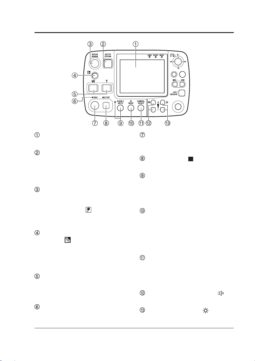
Control Reference Guide
Front panel
RETURN
CONTROL PANEL
LCD panel
Shows images and operation menus.
1, 2
AUTO ZOOM button
∗
Provides automatic control of zoom-in,
pause and zoom-out operation.
The officer can set zoom ratio and
pause time. (see page 19.)
2
BOOK MARK button
∗
Press during recording or playback
to enter bookmarks. A set bookmark
displays an icon
on the display
for 1 to 2 seconds when pressed.
(see pages 23 and 26.)
Backlight compensation
button ( )
1, 2
∗
Press to compensate for strong
backlighting. This button toggles
between ON and OFF at each press.
(see page 19.)
1, 2
Zoom buttons
∗
Use these buttons to zoom out (Wbutton) and zoom in (T-button).
(see page 19.)
REC lamp
Lights or flashes during recording.
(see page 52.)
REC button
Press to start recording video and
sound to P2 card. (see page 23.)
STOP button ( )
Stops recording. (see page 23.)
AUDIO2 MUTE button/lamp
Starts/releases recording for AUDIO2.
Pressing this button turns the lamp
on/off. While the lamp is lit, AUDIO2 is
not being recorded. (see page 19.)
IR MODE button
Switches the IR mode to one of the
following modes.
AUTO
:
Automatically changes IR mode
depending on ambient brightness.
ON: Turns on the IR mode.
OFF: Turns off the IR mode.
CAMERA SELECT button
Selects a camera.
CAMERA1 input: separately sold Color Camera
CAMERA2 input:
(see page 19.)
Volume control buttons ( )
Adjusts speaker sound volume.
Brightness button ( )
Adjusts LCD panel brightness.
MENU
ON/
OFF
2
∗
2
∗
1
∗
commercially available camera
∗1
A commercially available camera connected to the [CAMERA2] connector cannot be controlled.
∗2
The lamp turns on when the [CONTROL PANEL ON/OFF] button is set to ON.
9
Page 10
Control Reference Guide
Front panel
(continued
RETURN
CONTROL PANEL
)
MENU
ON/
OFF
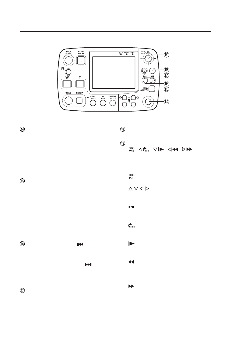
CONTROL PANEL ON/OFF button
Turns on and off he LCD panel, lamp
indications and buttons when the
Memory Card Video Recorder is on.
It cannot turn on or off the Memory
Card Video Recorder or this unit
(see page 19).
LIVE/ARCHIVE button
Switches between the live and
playback screen. (see pages 19 and
24.) Press this button to open the
Live screen when the “Information”
screen, “Archive” screen, “Restore”
screen, Officer setup top screen or
Setup/Admin top screen is displayed
(see pages 44 - 51).
Skip back button ( )
Press to return playback to the
previous skip location. (see page 26.)
Skip forward button ( )
Press to move playback the next skip
location. (see page 26.)
RETURN button
Returns to the previous menu or
screen. (see page 15.)
MENU button
Opens menus on the LCD panel.
Cursor buttons
( , , , , )
Use these buttons to manipulate
menus and control playback.
• During menu operation
] : Press the center position of
[
the button to confirm an entry.
[ , , , ] : Press to move the cursor
or change a set value.
• During playback
] : Press the center position of
[
the button to toggle between
playback and pause.
] : Press to return to a playback
[
position that is 7 seconds
earlier.
] : Engages slow playback. Each
[
press changes playback
speed between 1/10 and 1/2.
] : Press to rewind.
[
Each press changes the
rewind speed from x4 to x20
and x200.
] : Press to fast forward.
[
Each press changes the fast
forward speed from x4 to x20
and x200.
10
Page 11
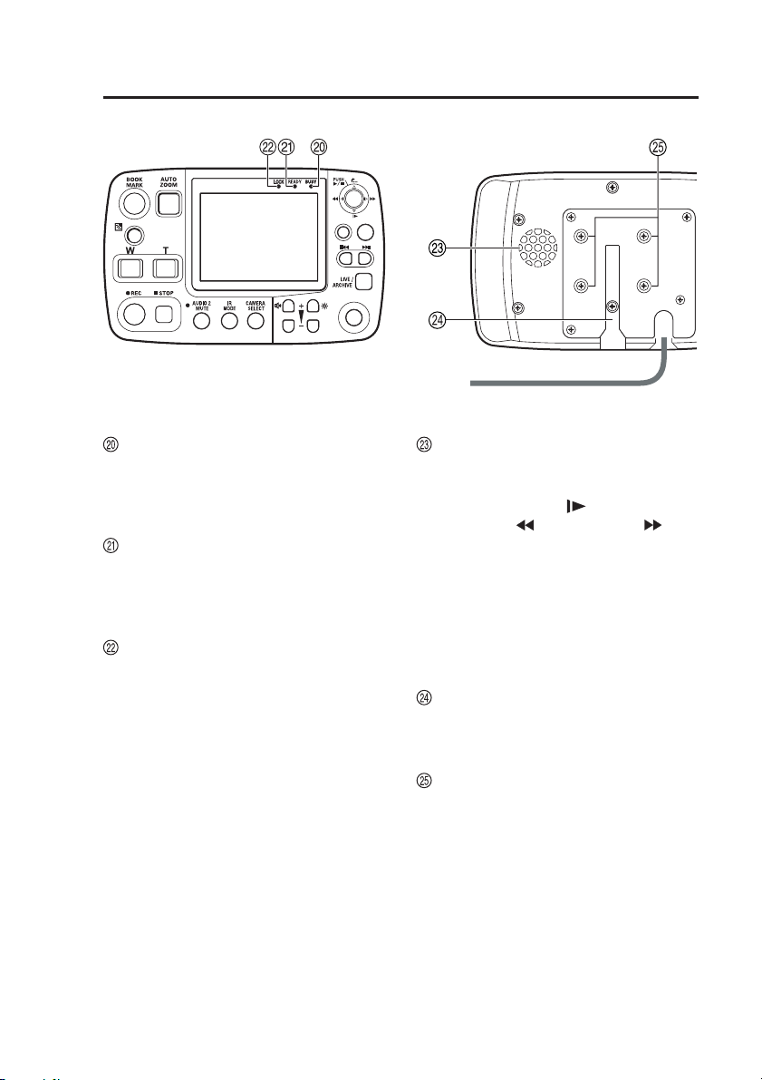
Control Reference Guide
(continued)
Front panel
RETURN
CONTROL PANEL
BUSY lamp
Lights or blinks when accessing a P2
card (for example during recording
and playback). (see page 52.)
READY lamp
Lights, flashes or goes off to indicate
whether or not a P2 card can be
recorded. (see page 52.)
LOCK lamp
Indicates whether or not buttons
other than the [REC], [MENU],
[CONTROL PANEL ON/OFF] and
[RETURN] buttons are locked.
MENU
ON/
OFF
Rear panel
Speaker
In playback screen mode:
Outputs audio. However,
during [
[
] slow playback,
] rewind, and [ ] fast
forward, audio is not output.
In Live screen mode:
The audio sound track is
not normally available.
Read the instructions
under “Checking audio”
on page 21 for details.
Anchoring groove
Provides attachment for a commercially
available stand.
Securing screw holes
Use the supplied screws to attach
a commercially available mounting
bracket.
11
Page 12
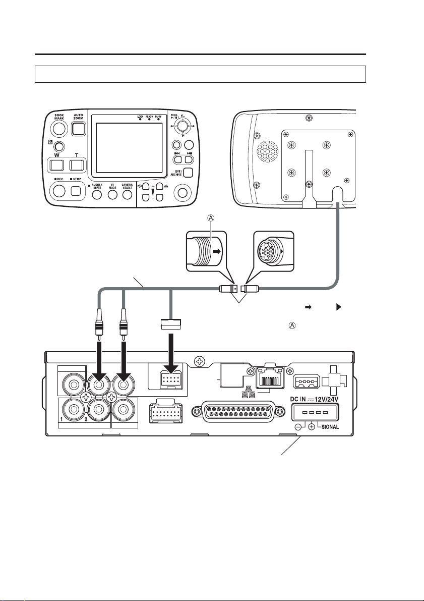
Connections
For details on installation and connections, be sure to consult your supplier.
[Front panel]
Control panel cable(included)
White Yellow
VIDEO OUT
AUDIO OUT
IN CAR MIC
RETURN
CONTROL PANEL
CONTROL PANEL
MENU
ON/
OFF
When connecting
When removing :
GPS-ANT.
(OPTION)
[Rear panel]
Align the “ ” and “ ”
:
marks to connect.
Slide in the reverse
direction of the arrow to
disconnect the connector.
USB
12
AUDIO IN
CAMERA 2
CAMERA 1
GPIO/SERIAL
Memory Card Video Recorder
(separately sold)
Page 13
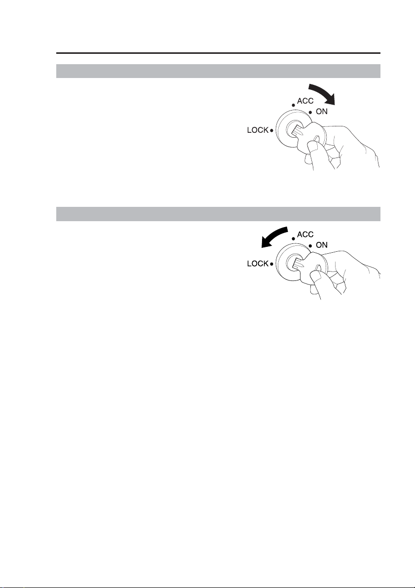
Turning the Remote Control Panel On and Off
On
Turn the vehicle’s ignition switch
to ON or ACC.
This turns on the Memory Card Video
Recorder and this unit.
Off
Turn the vehicle’s ignition switch
to LOCK (OFF).
This turns off the Memory Card
Video Recorder and this unit.
Notes:
• The power cannot be turned off by
pressing the [CONTROL PANEL
ON/OFF] button.
Setting the “PowerOff Time” (see
•
page 32) makes it possible to power
a Memory Card Video Recorder
and this unit for up to 180 minutes
even after the ignition switch is set
to the LOCK position.
13
Page 14
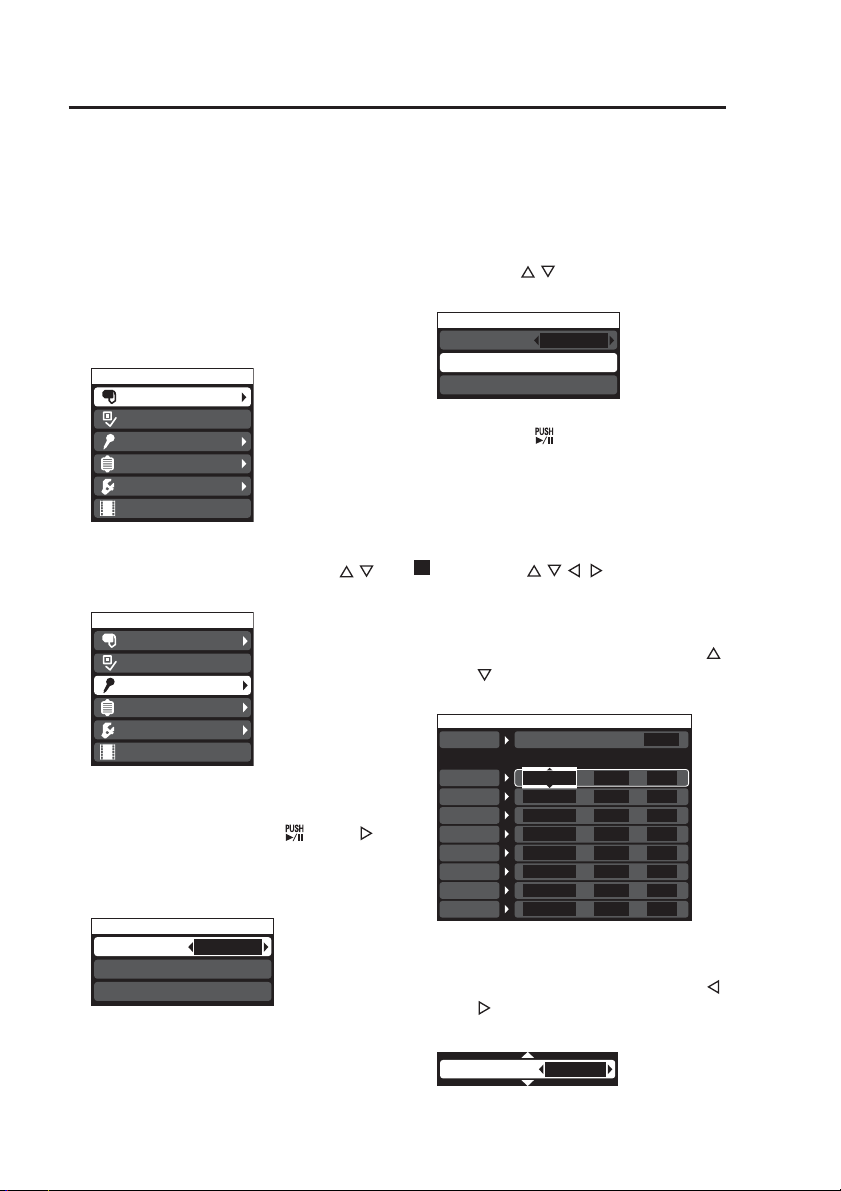
Basic Menu Operations
Use the LCD panel menus for operations and settings that cannot be performed
with the front panel buttons.
A list of all menus is provided on pages 44 to 51.
(This list also describes menus available only to administrators.)
Example: Test of Audio1
1. Press the [MENU] button.
The Menu appears.
A triangle displayed at the right
edge of a menu item indicates that
it contains a submenu.
Menu
Camera
RecCheck
Audio
Archive
Setup/Info
Restore
4. Use the [ , ] buttons to select
[Audio1 Test].
Audio
Audio2 Select
Audio1 Test (Press ENTER Key)
Audio2 Test (Press ENTER Key)
5.
Press the [ ] button to confirm
INCAR
the entry.
The Audio1 test is now ready to run.
2. Use the cursor buttons [ , ]
to select an item.
Menu
Camera
RecCheck
Audio
Archive
Setup/Info
Restore
3. Press the center position of
the cursor button [ ] or [ ]
to confirm the entry.
The selected item opens to reveal
selection details.
Audio
Audio2 Select
Audio1 Test (Press ENTER Key)
Audio2 Test (Press ENTER Key)
INCAR
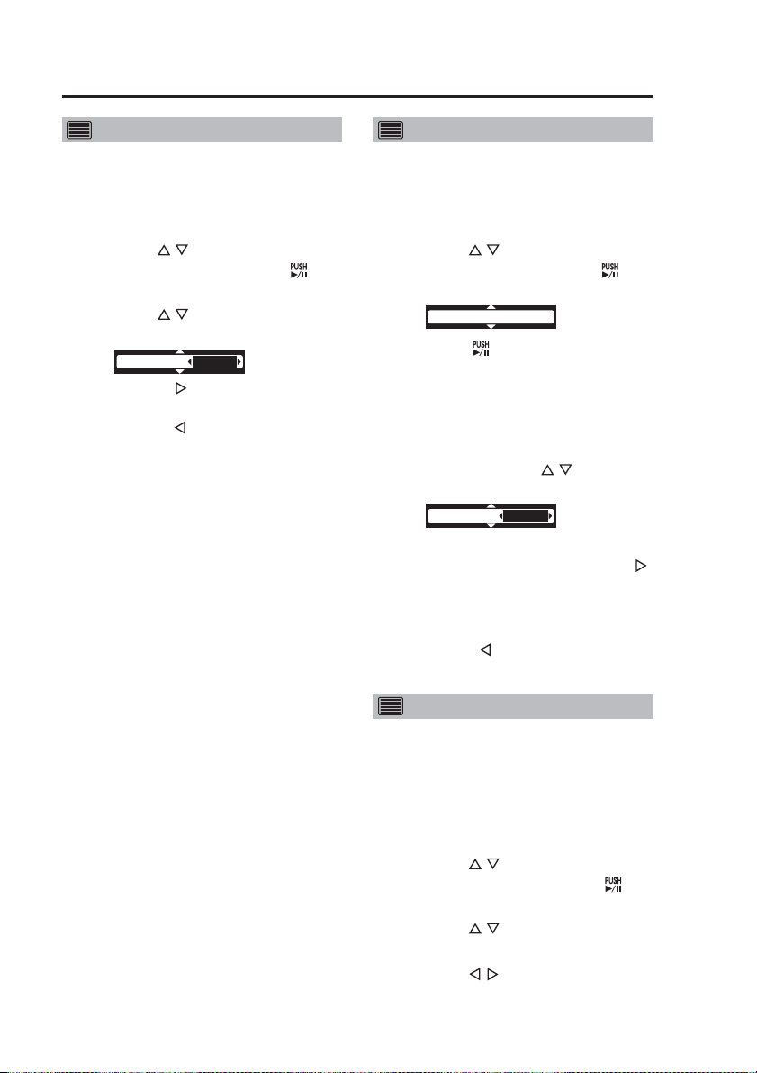
Use the [ , , , ] buttons to
set a value.
• A selected item with tiny triangles
at the top and bottom allow you to
change its value by pressing [
].
or [
(Screen example)
Trigger
GPIO
Trigger1
Trigger2
Trigger3
Trigger4
Trigger5
Trigger6
Trigger7
Trigger8
Detection OSD
N OFF
N OFF
N OFF
N OFF
N OFF
N OFF
N OFF
N
• A selected item with tiny triangles
to the left and right allow you to
change its value by pressing [
].
or [
(Screen example)
AE[-2 -- +2]
0
ON
Printable
-
-
-
-
-
-
-
OFF -
]
]
14
Page 15

Basic Menu Operations
Returning to previous screen
Press the [RETURN] button to return
to the previous screen. The menu is
cleared when the “Archive” screen,
Officer setup top screen or Setup/
Admin top screen is displayed.
Long menus
Menus with arrows at the top and
bottom contain items that are
currently not shown.
(continued)
15
Page 16
Setting up/Deleting Officer Data
Before using the Memory Card Video
Recorder, you must create and configure
officer data, such as an officer ID and
officer name. For details on creating officer
data, refer to the Operating Instructions of
the Memory Card Video Recorder.
Three setup methods are available, called
the AUTO, MANUAL and LIST modes.
Check with the administrator which
mode is selected. (see page 38.)
AUTO mode
When a USB memory device is connected
to the Memory Card Video Recorder, or
when connection is detected after turning
power on, the officer data for one or
two officers is automatically read in and
activated (see the Operating Instructions
of the Memory Card Video Recorder).
Connect a USB memory device
containing officer data to a
Memory Card Video Recorder.
The [READY] lamp flashes for
one second:
This indicates that the data was
correctly read.
The [BUSY] lamp flashes for one
second:
This indicates that the data could
not be correctly read.
Disconnect the USB memory
device and then reconnect it. If
the [READY] lamp does not flash
when the USB memory device
is connected again, check if the
officer data file has been correctly
saved to the USB memory device.
If the above measures do not
correct this problem, replace the
USB memory device.
Notes:
•
If a USB memory device is connected
and the officer data is read during
recording, the file will be split up
at the location where reading was
effectuated.
16
• Once the officer data has been
read, the USB memory device
may be removed.
• Once the officer data has been
set up, it is not deleted even when
power is turned off or the mode
changed.
MANUAL mode
Display the menu on the LCD panel.
Then read and load the officer data
from the Officer setup top screen.
1. Press the [MENU] button.
The Menu appears.
2. Use the [,] buttons to select
[Setup/Info] and press [ ] to
confirm the entry.
3. Use the [ , ] buttons to select
[Officer] and press [ ] to
confirm the entry.
The Officer setup top screen appears.
4.
Connect a USB memory device
containing officer data to a
Memory Card Video Recorder.
5. Use the [,] buttons to select
[Officer1].
6.
Use the [ , ] buttons to select
[Load] and press [ ] to confirm
the entry.
This registers officer1 and the name
and ID appear.
7. To enter officer2, replace the
current USB memory device
with a USB memory device
containing data for officer2.
8. Use the [ , ] buttons to select
[Officer2].
9.
Use the [ , ] buttons to select
[Load] and press [ ] to confirm
the entry.
This registers officer2 and the name
and ID appear.
Page 17

Setting up/Deleting Officer Data
(continued)
LIST mode
Open the menu on the LCD panel and
read in the officer data registered in
the Memory Card Video Recorder from
the Officer setup top screen.
For details on registering officer data,
see “Load Officer” in the “Administrator
Setup” (see page 35).
1. Press the [MENU] button.
The Menu appears.
2. Use the [ , ] buttons to select
[Setup/Info] and press [ ] to
confirm the entry.
3.
Use the [ , ] buttons to select
[Officer] and press [ ] to
confirm the entry.
The Officer setup top screen appears.
4. Use the [ , ] buttons to select
[Officer1].
5. Use the [ , ] buttons to select
[Select] and press the [ ]
buttons to confirm the entry.
A list of officers registered in the
Memory Card Video Recorder appears.
6.
Use the [ , ] buttons to select
an officer, (use the [ , ] buttons
to go between pages) and press
[ ] to confirm the entry.
The Officer setup top screen
appears when officer1 has been set.
7. Use the [ , ] buttons to select
[Officer2].
8. Use the [ , ] buttons to select
[Select] and press [ ] to
confirm the entry.
A list of officers registered in the
Memory Card Video Recorder appears.
9.
Use the [ , ] buttons to select
an officer, (use the [ , ] buttons
to go between pages) and press
[ ] to confirm the entry.
The Officer setup top screen
appears when officer2 has been set.
Deleting entered data
1. Press the [MENU] button.
The Menu appears.
2. Use the [ , ] buttons to select
[Setup/Info] and press [ ] to
confirm the entry.
3. Use the [ , ] buttons to select
[Officer] and press [ ] to
confirm the entry.
The Officer setup top screen appears.
4. Use the [ , ] buttons to select
[Officer1] or [Officer2].
5. Use the [ , ] buttons to select
[Delete] and press [ ] to
confirm the entry.
This deletes officer data selected in
Step 4.
Note:
Officer data cannot be deleted in
“AUTO mode”.
17
17
Page 18
Locking and Unlocking Buttons
This function is provided to prevent
incorrect input through the inadvertent
pressing of buttons.
Locking
1. Press the [MENU] button.
The Menu appears.
2. Use the [ , ] buttons to select
[Setup/Info] and press [ ] to
confirm the entry.
3. Use the [ , ] buttons to select
[Officer] and press [ ] to
confirm the entry.
The Officer setup top screen appears.
4. Use the [ , ] buttons to select
[Operation Key Lock].
5. Use the [,] buttons to select
“ON”.
The [LOCK] lamp lights, and the
buttons other than the [REC],
[MENU], [CONTROL PANEL ON/
OFF] and [RETURN] buttons, the
[REC] button on the Memory Card
Recorder, and the [REC] button on
the Color Camera are locked.
Notes:
•
The button lock function is engaged
after returning to the Live screen.
•
The key lock function in the
administrator setup (see page 38)
is independent of officer setup, so
that when locked by administrator
setup, the keys cannot be unlocked
from officer setup.
• The Color Camera zoom and
brightness buttons cannot be
locked.
Unlocking
1. Press the [MENU] button.
The Menu appears.
2. Use the [ , ] buttons to select
[Setup/Info] and press [ ] to
confirm the entry.
3. Use the [ , ] buttons to select
[Officer] and press [ ] to
confirm the entry.
The Officer setup top screen appears.
4. Use the [ , ] buttons to select
[Operation Key Lock].
5. Use the [,] buttons to select
“OFF”.
The [LOCK] lamp goes off and the
buttons are unlocked.
18
Page 19
Viewing Live Video
Use the functions described below to
manipulate video output by the camera
and sound from the microphone.
Press the [LIVE/ARCHIVE] button to
view live video. A commercially available
camera connected to the [CAMERA2]
connector cannot be controlled.
Selecting a camera
Press the [CAMERA SELECT] button.
Each press of the button toggles the
unit between the “CAMERA1” and
“CAMERA2” inputs.
CAMERA1 :
CAMERA2 :
Color Camera connected to
the [CAMERA1] connector
Commercially available
camera connected to the
[CAMERA2] connector
Note:
Selecting “CAMERA2” disables the
following “CAMERA1” operations.
• Adjusting image brightness
• Adjusting image focus
Zooming
To view the overall scene, press the
[W] button and zoom out.
To view fine details, press the [T]
button and zoom in.
1. Press the [W] button or the [T]
button.
The camera zooms in or out while
the button is kept depressed.
2.
Release the button when reaching
the desired image size.
Pressing [AUTO ZOOM] zooms in
the image to the target ratio and
then pauses before zooming out
towards the wide angle end. When
the zoom in operation goes beyond
the target ratio, it first zooms out to
the target ratio.
Making a backlit image easier to view
A dark subject against a bright
background can be made easier to view.
Press the [ ] button
This button toggles between “ON” and
“OFF” at each press.
Set this button to “OFF” for normal
operation.
Making a dark image easier to view
Use the infrared mode to make dark
images easier to view.
Press the [IR MODE] button.
IR
The
Each press of this button switches the
function from “AUTO”, “ON” and “OFF”.
Set this function to “AUTO” for normal
operation.
ON
appears.
Note:
This function can be used together
with “Adjusting image brightness” to
make an image brighter.
To mute AUDIO2 input sound
Press the [AUDIO2 MUTE] button.
Each press of this button toggles the
button between record and mute.
Note:
It is not possible to switch AUDIO1
sound recording in this manner.
Turning off the LCD panel
Press the [CONTROL PANEL ON/
OFF] button.
This turns off the LCD panel and lamps
and disables all button functions.
Pressing this button a second time
turns on the LCD panel and lamps
and button operations again become
available.
19
Page 20
Viewing Live Video
(continued)
Adjusting image brightness
This menu is available only when
“CAMERA1” is selected.
1. Press the [MENU] button.
The Menu appears.
2. Use the [ , ] buttons to select
[Camera] and press [ ] to
confirm the entry.
3. Use the [ , ] buttons to select
[AE [-2 -- +2]].
The
AE[-2 -- +2]
0
appears.
4. Press the [ ] button to make
the image brighter.
Press the [ ] button to make
the image darker.
Set this button to “0” (zero) for
normal operation.
Note:
When “CAMERA2” is selected in
[CAMERA SELECT], [Camera]
cannot be selected and brightness
cannot be adjusted.
Adjusting image focus
This menu is available only when
“CAMERA1” is selected.
1. Press the [MENU] button.
The Menu appears.
2. Use the [ , ] buttons to select
[Camera] and press [ ] to
confirm the entry.
Auto Focus (ENTER)
The
appears.
3. Use the [ ] button to confirm
the entry.
The autofocus function automatically
focuses the image.
4. When the autofocus function
cannot properly focus the
image, use the [ , ] buttons
to select [Manual Focus].
The
Manual Focus
NF
appears.
5. To focus on a more distant
subject, hold down the [ ]
button and release it when it
comes into focus.
6.
To focus on a closer subject, hold
down the [ ] button and release
it when it comes into focus.
20
To turn off the [REC] lamp during recording
The “CAMERA1” (Color Camera)
[REC] lamp lights during recording. The
following steps allow you to keep this
lamp off at all times.
1. Press the [MENU] button.
The Menu appears.
2. Use the [ , ] buttons to select
[Setup/Info] and press [ ] to
confirm the entry.
3. Use the [ , ] buttons to select
[Camera LED].
4. Use the [,] buttons to select
“OFF”.
The lamp will now remain off at all
times.
Page 21

Viewing Live Video
(continued)
Selecting AUDIO2 input
1. Press the [MENU] button.
The Menu appears.
2.
Use the [ , ] buttons to select
[Audio] and press [ ] to
confirm the entry.
3. Use the [ , ] buttons to select
[Audio2 Select].
4. Use the [,] buttons to select
“INCAR” or “WMIC”.
INCAR :
Sound input through the [IN CAR
MIC] terminals
WMIC (Wireless Microphone) :
Sound input through the [AUDIO
IN 2] terminals
Checking audio
Sound output is normally off when
viewing live video. Use the following
steps to check that sound is input
normally.
1. Press the [MENU] button.
The Menu appears.
2. Use the [ , ] buttons to
select [Audio] and press [ ]
to confirm the entry.
3.
Use the [ , ] buttons to select
[Audio1 Test] or [Audio2 Test],
and then press the [ ] button.
Sound is output while the [ ] button
is depressed.
Note:
The output sound may be too loud
depending on the sound volume
setting. Lower the sound volume as
required.
Viewing Memory Card Video Recorder status
The following function is provided to
enable viewing Memory Card Video
Recorder status and GPIO status.
1. Press the [MENU] button.
The Menu appears.
2. Use the [ , ] buttons to select
[Setup/Info] and press [ ] to
confirm the entry.
3. Use the [ , ] buttons to select
[On Screen Type].
4.
Use the [ , ] buttons to select
“SIMPLE”, “DETAILS” or “OFF”.
SIMPLE:
The simple On-Screen Display
appears.
DETAILS:
The detailed On-Screen Display
appears.
OFF:
The On-Screen Display closes.
Notes:
•
The administrator can set the
Overlay OSD (Init On Screen Type)
selected at power-on.
• See the next page for how to read
the On-Screen Display.
21
Page 22

Viewing Live Video
<Simple On-Screen Display>
C1 IRA BL TAL LOCK
<Detailed On-Screen Display>
000
OWN /TGT MPH
---
--
.
----------
---
.
---------
(continued)
REMAIN 4:12 min
Restore
REMAIN 4:12 min
2006-08-25 14:51:19
TRIGGER A B
Speed (MPH / KPH)
OWN : own vehicle speed
TGT : target vehicle speed
Target vehicle speed indication
depends on the type of radar gun
that is connected. For example, one
ProLaser3 measurement indicates
vehicle speed for a period of about
10 seconds. If another measurement
is made within this 10 second period
(approx.), the speed indication is
updated accordingly.
Note:
“ERR” appears to indicate that the
radar gun measurement result is
not correct.
Location information (latitude)
Location information (longitude)
Remaining P2 card recording time
(HHH : MM)
• The remaining recording time is
updated about every 30 seconds.
• When loop recording is set to
“ON”, the loop interval (total
recording time) is displayed.
Note:
The total recording time does
not include prerecording and
postrecording time.
22
Restore
C1 IRA BL TAL LOCK
Mode indication
(
: paused : recording)
Status display
PON: power ON recording “ON”
<Status Display> (see page 58)
CARD FULL, CARD PROTECT,
VUP CARD, UNFORMATTED,
ILLEGAL CARD, NO CARD
Remaining time on the P2 card
Date/Time
Trigger input status
(GPIO 1 to 8 are displayed in order
from the left.)
The letters assigned by [Printable]
appear only when H level is set.
Appears only when there is a file
that should be restored
Mark position
: Bookmark position
: Trigger position
: File beginning
Memory Card Video Recorder
setup status
C1 : Camera1 selected
C2 : Camera2 selected
IR : Camera IR mode is “ON”
IRA : Camera IR mode is “AUTO”
BL : Camera backlight
compensation is “ON”
TAL : Camera lamp is “ON”
LOCK : Operation button lock is “ON”
Page 23

Recording
Starting and stopping recording
Starting recording
Press the [REC] button.
This starts video and sound recording.
The live screen appears automatically if
not already on. The Memory Card Video
Recorder, the Color Camera and this
unit [REC] lamps go on during recording.
Note:
The Color Camera [REC] lamp goes
on regardless of camera input setting
(for example, “CAMERA2” being
selected with the [CAMERA SELECT]
button).
The following methods also enable
start of recording. But these methods
require administrator setup.
•When the GPIO recording trigger
criteria is met.
•When set speed for own vehicle or
target vehicle is exceeded.
•When the vehicle ignition switch is
set to ON and power ON recording
has been set to “ON”.
•When the start time of programmed
recording
Stopping recording
Press the [STOP] button ( ).
Pressing the [STOP] button turns off
the [REC] lamp and video and sound
recordings stop when the post record
interval has elapsed. Then the [BUSY]
lamp goes off.
Recording stops also under the
following conditions.
• There is no more space left on the
P2 card.
1
∗
is reached.
2
∗
When the P2 card slots cover on the
•
Memory Card Video Recorder is open.
When an administrator setup is started.
•
• When the GPIO trigger level criteria
is met (requires administrator setup).
When the Rec Continue Time has
•
elapsed (requires administrator setup).
•
When a defect is detected on a P2 card.
•When the stop time of programmed
recording
1
∗
is reached.
Adding bookmarks
A bookmark can be added to a file
that is being recorded to mark it for
playback. (see page 26.)
Press the [BOOK MARK] button.
The bookmark icon [ ] appears for 1
or 2 seconds.
Notes:
•
The bookmark icon appears on the
On-Screen Display. When the OnScreen Display is not displayed, it
appears on the LCD panel.
• Bookmarks can be added with a
minimum interval of 2 seconds.
• A bookmark cannot be entered
until about five seconds after
recording starts.
• It is possible to move the playback
location to the bookmark during
playback.
• Bookmarks can be added also
during playback. (see page 26.)
• Bookmarks can be deleted only
during playback. (see page 26.)
For details, refer to “Starting and Stopping Recording → Programmed recording”
∗1
in the Operating Instructions of the Memory Card Video Recorder.
∗2 Post record is a function that continues recording for a preset interval after
recording is turned off. Changing the setting requires administrator setup.
23
Page 24

Recording
(continued)
A trial shoot
The following is a description of a test to
check if recording can be correctly made.
1. Press the [MENU] button.
The Menu appears.
2. Use the [ , ] buttons to select
[RecCheck] and press [ ] to
confirm the entry.
A five-second recording is made
and played back.
Notes:
• A trial shoot cannot be performed
during recording or playback.
• The trial shoot portion of a
recording is automatically deleted
after playback.
Starting and stopping intermittent recording
When intermittent recording is set in
administrator setup, normal recording
may take place in addition to intermittent
recording.
The table below shows under what
conditions a button operation, recording
trigger, recording stop criteria or other
input will start normal recording, start
intermittent recording or stop recording.
Input
[REC] button
pressed
[STOP]
button
pressed
Recording
trigger input
When a
recording stop
criteria other
than the [STOP]
button is met
Previous
status
Recording
stops
Normal
recording,
Intermittent
recording
Normal
recording stops,
Intermittent
recording
Normal
recording
Subsequent
status
Intermittent
recording
Recording
stops
Normal
recording
Intermittent
recording
Playback
Playback
Press the [LIVE/ARCHIVE] button.
The playback screen appears and
playback starts from the location where
playback was last made.
If recording was started or stopped
prior to pressing the [LIVE/ARCHIVE]
button, playback starts from the
beginning of the recorded file.
Notes:
• In the following cases, recorded
files may not be played back from
the beginning.
24
•
When [Setup/Admin]-[Date/Time][Date/Time] is changed
•
When [Setup/Admin]-[Date/Time][TimeZone] is changed
• When [Setup/Admin]-[Rec/Play][Rule of Filename] is changed
•
When the clock time is corrected
by GPS
• If playback was previously ended
at the end of the file, playback is
paused.
• If the LCD panel is turned off by
using the [CONTROL PANEL ON/
OFF] button, file playback stops.
Page 25

Playback
(continued)
Name of record file
A record file name that appears in the
On-Screen Display or playback file list
screen takes a name that is based on
the local time when recording started.
It is indicated in the format:
Year - Month - Day Hour: Min.: Sec.
Note:
A physical filename (for example, a
filename that appears on a PC) can be
indicated either in world or local time
depending on administrator setup.
Intermittent recording files
An intermittent recording file records
only one video frame per second but
no audio.
Note:
The playback speed of an intermittent
recording file is slower than a normal
file.
Loop recording files
A loop recorded file is automatically
split up and the recording start time at
the split point becomes the name of
the file.
Changing playback method
Playback and pause
Press the [
Playback starts. Press again to pause
playback. Use this button to pause
slow, rewind and fast forward.
] button.
Slow
Press the [ ] button.
Slow plays back at 1/10 or 1/2 of normal
speed. Each press changes playback
speed from 1/10 to 1/2 and 1/10.
Note:
Intermittent recording files cannot
be played back at slow speed.
Quick Replay
Press the [ ] button.
Playback starts 7 seconds prior to the
current location. During slow playback,
slow playback starts 7 seconds prior to
the current location.
Rewinding
Press the [ ] button.
Rewinding is performed at 4, 20 or 200
times normal speed.
Each press changes the rewind speed
from 4, to 20, 200 and back to 4 times
normal speed.
Fast forward
Press the [ ] button.
Fast forwarding is performed at 4, 20
or 200 times normal speed.
Each press changes the fast forward
speed from 4, to 20, 200 and back to 4
times normal speed.
25
Page 26

Playback
(continued)
Moving back to a previous
skip location to start playback
Press the [
Playback starts from the previous skip
location.
If the current location is 5 seconds
or less away from a skip location,
playback starts from the skip location
before the previous skip location.
However, if the current location is 5
seconds or less away from the first skip
location in the file, playback starts from a
skip location in the previous file.
If there is no previous file, playback starts
from the current location without skipping.
] button.
Moving to the next skip
location to start playback
Press the [ ] button.
Playback starts from the next skip location.
If the current location comes after the last
skip location in the file, playback starts
from a skip location in the next file. If
there is no next file, playback starts from
the current location without skipping.
Notes:
•
The skip location may be a bookmark,
head of file or a trigger position (one
per file) at which recording began.
However, no trigger position can exist
in automatically divided files.
• One of the following icons may
appear On-Screen for about
2 seconds depending on the
location playback skips. When not
shown in an On-Screen Display,
they appear on the LCD panel.
: Bookmark position
: Trigger position
: File beginning
When these icons coincide, they
are indicated in the following order
of priority: bookmark position,
trigger position and file beginning.
•
It is recommended that the skip
location be placed at the [Trigger/
Marker] or [Head of File] in the
administration setup. (see page 34.)
•
Up to 999 bookmarks can be skipped.
You cannot skip to the bookmark
position exceeding this limit.
• When the [ ] button or [ ]
button is pressed, playback stops
momentarily while the skip location
is searched for, and then playback
resumes from that position.
Adding bookmarks
Adding bookmarks
Bookmarks can be added during
playback, pause or slow playback.
Press the [BOOK MARK] button.
• A bookmark icon appears.
• Playback or slow playback stops for a
short while and then resumes.
Notes:
• The bookmark icon appears on the
On-Screen Display. When the OnScreen Display is not displayed, it
appears on the LCD panel.
• Bookmarks can be added with a
minimum interval of 2 seconds.
Playing back a segment with a
•
bookmark shows a bookmark icon
for about 2 seconds during playback.
Deleting bookmarks
Press the [BOOK MARK] button
when a bookmark icon appears
during playback, pause or slow
playback.
• This deletes the bookmark icon .
• Playback or slow playback stops for a
short while and then resumes.
Note:
Bookmarks cannot be added or
deleted during rewind and fast
forward.
26
Page 27

Playback
(continued)
Selecting a file for playback
1. Press the [MENU] button.
The Menu appears.
2. Use the [ , ] buttons to select
[Archive] and press [ ] to
confirm the entry.
The playback file list screen appears.
Notes:
• Files appear in the order of the
filenames (see page 33) that are
assigned at recording.
“WT” (world time) files are displayed
in recording start order (but the time is
converted and indicated in local time)
↓
“LT” (local time) files are displayed
in recording start order.
•
When a file is recorded across two
P2 cards and is split into two files,
the start time of the latter file is
suffixed by “∗”. Also, if two or more
files have the same start time,
the start time of the second and
succeeding files are suffixed by “∗”.
3.
Use the [ , ] buttons to select a
file to play back. (Use the [ , ]
buttons to go between pages.)
4. Use the [ ] button to start
playback.
Playback starts from the beginning
of the file.
When playback reaches end of the
file, playback is paused.
Turning Audio1 and 2 ON and OFF
1. Press the [MENU] button.
The Menu appears.
2. Use the [ , ] buttons to select
[AUDIO].
3. Use the [ , ] buttons to select
[Audio1] or [Audio2].
4.
Use the [ , ] buttons to select
“ON” or “OFF”.
Note:
An administrator can set the audio
output (Init Audio Out (Play))
selected at power-on.
Viewing Memory Card Video Recorder status
Use the following function to see the
Memory Card Video Recorder status
or GPIO status when a played back file
was recorded.
1. Press the [MENU] button.
The Menu appears.
2. Use the [ , ] buttons to select
[Setup/Info] and press [ ] to
confirm the entry.
3. Use the [ , ] buttons to select
[On Screen Type].
4.
Use the [ , ] buttons to select
“SIMPLE”, “DETAILS” or “OFF”.
SIMPLE:
The Simple On-Screen Display
appears.
DETAILS:
The Detailed On-Screen Display
appears.
OFF:
On-Screen Display closes.
Notes:
•
An administrator can set the
Overlay OSD (Init On Screen Type)
selected at power-on.
• See the next page for how to read
the On-Screen Display.
27
Page 28

Playback
(continued)
<Simple On-Screen Display>
<Detailed On-Screen Display>
2006-08-25 14:45:05
x1/10
Restore
000
OWN /TGT MPH
2006-08-25 14:51:19
TRIGGER A B
---
--
.
----------
---
.
---------
Speed (MPH / KPH)
OWN: own vehicle speed
TGT: target vehicle speed
Location information (latitude)
Location information (longitude)
Playback filename
(Local time at start of recording)
“NO FILE” appears when there is
no file to play back.
Mode indication
: Playback
: Pause
: Fast forward
: Rewind
: Slow
Playback speed and status indication
<Speed>
x1/10, x1/2, x4, x20, x200
<Status Display> (see page 58)
READ ERROR, META ERROR,
PLAY ERROR
2006-08-25 14:45:05
x1/10
Restore
Playback location (in file units)
Date/Time
Trigger input status
(GPIO 1 to 8 are displayed in order
from the left.)
The letters assigned by [Printable]
appear only when H level is set.
Appears only when there is a file
that should be restored
Mark position
: Bookmark position
: Trigger position
: File beginning
Sound output setting
: appears only during playback)
(
A1 : Audio1 is output
A2 : Audio2 is output
28
Page 29

Restoring Files
If the power of the Memory Card Video
Recorder is turned off or a P2 card is
removed during recording, the file will be
corrupted and cannot be played back.
[Restore] appears on the On-Screen
Display when there is a file on the P2
card that needs to be restored.
(This message does not appear when
[On Screen Type] is set to “OFF”.)
[Restore] in the Menu is normally
disabled, but is enabled upon detecting
a file that cannot be played back.
Use the following steps to process any
file that needs to be restored.
1. Press the [MENU] button.
The Menu appears.
2. Use the [ , ] buttons to select
[Restore] and press [ ] to
confirm the entry.
The Restore confirmation screen
appears.
3.
Use the [ , ] buttons to select
[Restore] and press
[ ]
to
confirm the entry.
This starts file restoring.
The screen prior to Step 1 above
reappears when the file is restored.
Select [Cancel] during a restoring to
cancel the restore process.
Notes:
• An interrupted restore process can
be resumed at a later time.
Recording is still available even if
•
there are files in need of restoration.
• A recording trigger detected during
a restore process or pressing the
[REC] button will interrupt the
process and start recording.
• Files that must be restored do not
appear on the playback file list
screen. Make sure to restore the
files beforehand.
• Since a seriously corrupted file
may not be possible to restore,
do not turn off the unit during P2
card access (for example, during
recording) and do not remove a
P2 card when the [BUSY] lamp is
lit or blinking.
29
Page 30

Displaying Product Information
Viewing software version
1. Press the [MENU] button.
The Menu appears.
2. Use the [ , ] buttons to select
[Setup/Info] and press [ ] to
confirm the entry.
3.
Use the [ , ] buttons to select
[Information] and press
[ ]
to
confirm the entry.
This opens the product information
screen that contains the software
version information.
Viewing error log data
Use the following procedure to open a
dialog showing up to five of the most
recent errors.
1. Perform steps 1 to 3 in
“Viewing software version”.
2.
This selects [Last Errors].
Press the [ ] button to accept.
This dialog shows the most recent
error data (the items listed below).
• Month/day (MM/DD)
• Hour/minute (HH : MM)
• Error No.
• Error type (Fatal Error/Error)
• Error message (the first 40
characters appear)
Notes:
•
Error data with a low priority is also
displayed.
• The following error numbers do
not appear as error log data.
E08601, E28201 to E28203
Rebooting the Memory Card Video Recorder
Should Memory Card Video Recorder
operating status become unstable,
use the following steps to reboot the
Memory Card Video Recorder.
1. Press the [MENU] button.
The Menu appears.
2. Use the [ , ] buttons to select
[Setup/Info] and press [ ] to
confirm the entry.
30
3. Use the [ , ] buttons to select
[Reboot] and press [ ] to
confirm the entry.
The Reboot confirmation screen
appears.
4.
Use the [ , ] buttons to select
“Reboot” and press [ ] to
confirm the entry.
A reboot takes between 40 to 50
seconds to complete.
Page 31

Administrator Setup
The Memory Card Video Recorder
setup includes items that only an
administrator is allowed to set up.
Log in at the Setup/Admin screen.
1. Use a computer to copy the
administrator’s officer data to
a USB memory device.
For details on creating a text file
with the administrator’s officer data,
refer to the Operating Instructions of
the Memory Card Video Recorder.
2.
Connect the USB memory device to
the Memory Card Video Recorder.
Notes:
• To protect the [USB] connector of
the Memory Card Video Recorder,
connect the USB extension cable
(included in the cable kit) and
connect the USB memory device
to the extension cable.
• For details on connecting, consult
your supplier.
3. Press the [MENU] button.
The Menu appears.
4. Use the [ , ] buttons to select
[Setup/Info] and press [ ] to
confirm the entry.
Note:
Some USB memory devices may
not be properly recognized.
5. Use the [ , ] buttons to select
[Admin] and press [ ] to
confirm the entry.
The first of the files automatically
sorted (in ascending order) from the
USB memory device is loaded as
the administrator’s officer data.
The Memory Card Video Recorder
searches to determine whether
officer data for the administrator has
already been registered, and in the
following cases, the Setup/Admin
top screen appears.
• When no officer data for the
administrator is registered, such
as immediately after purchase.
• When identical officer data
is already registered for the
administrator.
Setup/Admin [1/2]
Rec/Play
Programed Rec
Date/Time
Registration
Trigger
OSD
Camera
Management Mode
If officer data is already registered for
the administrator but is not identical,
the following screen appears before
the Menu automatically reappears.
Obtain correct data from the
administrator and repeat operations
from Step 1 above.
Authentication
Since you are not an administrator,
you cannot open this menu.
Note:
Refer to the Operating Instructions
of the Memory Card Video Recorder
for information on the factory
defaults.
31
Page 32

Administrator Setup
(continued)
Setup/Admin [1/2]
Rec/Play
Programed Rec
Date/Time
Registration
Trigger
OSD
Camera
Management Mode
Setup/Admin [2/2]
Radar/GPS
File Management
Auto Maintenance
Service
Rec/Play
PowerOff Time
Use this function to set the interval
after which the Memory Card Video
Recorder and this unit will shut down
after the ignition switch has been set
to the LOCK (OFF) position.
Setting (min.):
0/10/20/30/60/90/120/180
Init Camera Select
Select the camera selected at power-on.
1: Color Camera connected to
the [CAMERA1] connector
Commercially available camera
2:
connected to the [CAMERA2]
connector
LAST
: See footnote.
1
∗
Init Audio2 In Select
Select the Audio2 input selected at
power-on.
INCAR :Input signal of the [IN CAR
WMIC : Input signal of the [AUDIO
LAST : See footnote.
PowerOn Rec
Use this function to set recording to
start when the Memory Card Video
Recorder is turned on.
Setting : ON/OFF
Loop Rec
Use this function to record new data
by deleting the oldest files when there
is no free space left on a P2 card.
Setting : ON/OFF
Intermittent Rec
Use this function to record
video frame per second.
Setting : ON/OFF
Resolution/RecRate
Use th
is function to set the screen
resolution and the recording rate.
Q-512kbps :
320X240 512 kbps 30 fps
Q-1Mbps :
320X240 1 Mbps 30 fps
F-1Mbps :
720X480 1 Mbps 10 fps
F-2Mbps :
720X480 2 Mbps 30 fps
MIC] connector
IN 2] connector
1
∗
2
∗
one
∗1 Applies the setting in effect when power was last turned off. Unless power is
turned off properly, the operating state may not be saved correctly.
∗2 Normal recording records 10 or 30 video and audio frames per second.
32
Page 33

Administrator Setup
1
Rec Continue Time
Use this function to set recording
continue time for normal recording
when a trigger is entered or when
the [REC] button is pressed.
Setting (min.) : 1/2/5/10/15/20/30/
60/90/CONTINUE
PreRec Time (Video)
Use this function to set how much of
already stored video will be retained
when a trigger is entered or the
[REC] button is pressed.
Setting (sec.) : 0/10/20/30/60/90
PreRec Time (Audio)
Use this function to set how much of
already stored audio will be retained
when a trigger is entered or the
[REC] button is pressed. However,
the audio recording starts at the
same time when the video prerecording starts, even if the PreRec
Time (Audio) is set longer than the
PreRec Time (Video).
Setting (sec.) : 0/3/10/20/30/60/90
PostRec Time (Video)
Use this function to set the time
interval video recording will continue
after the [STOP] button is pressed.
Setting (sec.) : 0/10/20/30/60/90
∗
2
∗
2
∗
3
∗
(continued)
PostRec Time (Audio)
Use this function to set the time
interval audio recording will continue
after the [STOP] button is pressed.
However, the audio recording ends
at the same time when the video
postrecording ends, even if the
PostRec Time (Audio) is set longer
than the PostRec Time (Video).
Setting (sec.) : 0/3/10/20/30/60/90
Rule of Filename
Use this function to set the rules for
filenames generated during recording.
WT : World time
LT : Local time
CAM Select in Trigger
Use this function to select a camera
when a GPIO trigger starts recording.
1
2
NO CHANGE : No change is made to
Init Audio2 Rec
Sets AUDIO2 recording when the
power is turned ON.
ON : recording is performed
OFF : recording is not performed
LAST : See footnote.
3
∗
:
Color Camera connected to the
[CAMERA1] connector
:
Commercially available camera
connected to the [CAMERA2]
connector
the current setting
4
∗
∗1 Intermittent recording and programmed recording extended by Rec Continue
Time do not stop.
Intermittent recording and programmed recording do not include prerecording time.
∗2
∗3 If recording is stopped by Intermittent recording, programmed recording and
Rec Continue Time, postrecording is not included.
∗4 Applies the setting in effect when power was last turned off. Unless power is
turned off properly, the operating state may not be saved correctly.
33
Page 34

Administrator Setup
(continued)
Rec Tally Out
Enables or disables output of the
recording status as the GPIO9
signal. When enabled, a high level
(output voltage 5.0 V) indicates
recording is in progress.
Setting : ENABLE/DISABLE
Init On Screen Type
Use this function to set On-Screen
Display used when the power is on.
Setting : SIMPLE/DETAILS/
LAST
1
∗
/OFF
Init Audio Out (Play)
Use this function to set Audio Out
used when the power is on.
OFF : Audio1 and Audio2 are not
output.
1 : Audio1 is output
2 : Audio2 is output
BOTH : Both Audio1 and Audio2 are
output.
LAST : See footnote.
1
∗
Skip Target
Use this function to set the skip
location (the amount of time that is
skipped) when the [Skip back] or [Skip
forward] button is pressed.
Trigger / Marker
Playback jumps to the trigger
position (one per file) at which
recording began, or to a bookmark
position, whichever found earlier.
However, no trigger position can
exist in automatically divided files.
Setting : YES/NO
Head of File
Use this function to move to the
beginning of a file during playback.
Setting : YES/NO
Notes:
• When both [Trigger/Marker] and
[Head of File] are set to “YES”,
playback will restart from the first
trigger or bookmark that appears
or restarts from the beginning of
the file.
• [Trigger/Marker] and [Head of File]
cannot both be set to “NO”.
Programed Rec
Use this function to set recording to start
and stop every day or on a specified
day of the week.
2
∗
Daily
Makes daily recordings from the set
start time to the set stop time.
ON :
Start time and stop time can be set.
– : No setting is available.
Note:
When [Daily] is set to “ON”, the
[Mon] to [Sun] field changes to “–”
and no setting can be made.
2
Mon to Sun
Makes recordings from the set
start time to the set stop time on a
specified day of the week.
ON :
Start time and stop time can be set.
A time for the next day can be set.
– : No setting is available.
∗
∗1 Applies the setting in effect when power was last turned off. Unless power is
turned off properly, the operating state may not be saved correctly.
∗2 The <Duration> field indicates the time period from start time to stop time.
34
Page 35

Administrator Setup
(continued)
Notes:
• The start time must be set to a
time that comes at or later than
the stop time for the previous day.
When the stop time is set to the
•
same time as the start time or to a
time prior to the start time, the stop
time will be set for the next day.
• Even at a time outside of the set
start time and stop time period,
recording will start if the recording
start criteria is met, for example,
when a recording trigger is input
or the [REC] button is pressed.
• Programmed recording will start
if the power is turned on in the
period between the start time and
stop time.
• If auto maintenance is performed
during programmed recording,
recording will be interrupted for 40
to 50 seconds.
Date/Time
TimeZone
Indicates time difference from world
standard time.
Hawaii : Hawaiian standard time
Yukon : Alaska standard time
Yukon DST
Pacific : Pacific standard time
Pacific DST
Mountain : Mountain standard time
Mountain DST :
Central : Central standard time
Central DST :
Eastern : Eastern standard time
Eastern DST :
Atlantic : Atlantic standard time
Atlantic DST
Asia Tokyo
:
Alaska daylight saving time
:
Pacific daylight saving time
Mountain daylight saving time
Central daylight saving time
Eastern daylight saving time
:
Atlantic daylight saving time
: Japan standard time
Style
Use this function to set a date format.
ISO : YYYY-MM-DD
HH : MM : SS
USA : MM/DD/YYYY
HH : MM : SS
Date/Time
Set
Set [Date/Time] and press [Set] to confirm.
Setting : Year/month/day
hour : minute : second
Registration
Load Admin
Use this function to load administrator
data from a USB memory device,
overwriting any existing administrator
data.
Note:
No administrator data is registered
when shipped from the factory.
List Admin
Use this function to view the IDs of
administrators and officer names
already registered in the Memory
Card Video Recorder. Use the
buttons to go between pages.
Load Officer
Use this function to load officer
data from a USB memory device,
overwriting any existing officer data.
[ , ]
Note:
No officer data is registered when
shipped from the factory.
List Officer
Use this function to view the IDs of
officers and officer names already
registered in the Memory Card Video
[ , ]
Recorder. Use the
go between pages.
buttons to
35
Page 36

Administrator Setup
(continued)
Trigger
GPIO
Use this function to turn GPIO on
or off.
Setting : ON/OFF
Trigger1 - 7
< Detection >
Enter conditions for detection of triggers
1 – 7. Set unused triggers to “N”.
N : Input disabled
H : High-edge trigger
Level H : High-level trigger
L : Low-edge trigger
Level L : Low-level trigger
B : Double-edge trigger
< OSD >
Use this function to determine whether
or not GPIO signal status should be
indicated in the On-Screen Display.
Setting : ON/OFF
< Printable >
Use this function to assign a letter to
be shown on the On-Screen Display.
Setting : A - Z, –
Note:
The selected font appears when
<OSD> is set to “ON” and the GPIO
signal is high.
Trigger8
< Detection >
Enter conditions for detection of
trigger 8. When not used, set to “N”.
N : Input disabled
H : High-edge trigger
Level H : High-level trigger
L : Low-edge trigger
Level L : Low-level trigger
B : Double-edge trigger
SPEED : Detects vehicle speed
< OSD >
Use this function to turn On-Screen
Display on or off.
Setting : ON/OFF
< Printable >
Use this function to assign a letter to
be shown on the On-Screen Displays.
Setting : A - Z, –
Notes:
• When SPEED is selected, the
On-Screen Display (OSD) setting
and printable letters (Printable)
setting are both “–”, and cannot
be changed. Also, the screen is
not displayed.
• Check the pulse frequency
described on page 39 before
selecting SPEED. Turning SPEED
“ON” using an incorrect frequency
will generate an abnormal trigger.
OSD
OSD
Use this function to set whether the
On-Screen Display appears on the
screen and is included in record files.
Setting : ON/OFF
Display Position
Use this function to set the display
position for the On-Screen Display on
the screen and in record files.
L-Upper : Upper left
R-Upper : Upper right
L-Bottom : Lower left
R-Bottom : Lower right
Trigger
Use this function to turn trigger
display on or off upon GPIO 1 to 8
inputs.
Setting : ON/OFF
Note:
The Detailed On-Screen Display
(see pages 22 and 28) will hide this
indication.
36
Page 37

Administrator Setup
Time
Use this function to turn date
and time display on or off during
recording.
Setting : ON/OFF
Note:
The Detailed On-Screen Display
(see pages 22 and 28) will hide this
indication.
(continued)
AutoZoom Magnification
Use this function to set the target
zoom-in ratio.
Setting : ×1/×2/×3/×4/×5/×7/×10/
AutoZoom Time
Use this function to set the zoom-in
pause time.
Setting (sec.) : 3/5/8
×15/×22
Camera
Zoom Limit
Use this function to enter maximum
zoom ratio.
Setting : ×22/×220
AGC Level
Use this function to set the level of
camera input gain control.
Setting : LOW/MID/HIGH/OFF
Init Backlight
Use this function to turn backlight
compensation on or off when the
power is on.
Setting : ON/OFF/LAST
1
∗
Init AE Shift
Use this function to adjust
brightness when the power is on.
Setting : -2/-1/0/+1/+2/LAST
1
∗
Flip
Use this function to determine
whether to vertically flip camera
video image or not.
Setting : ON/OFF
Init Camera LED
Use this function to turn the camera
lamp on or off when the power is on.
Setting : ON/OFF/LAST
Init IR Mode
1
∗
Use this function to set the IR
function when the power is on.
Setting : AUTO
2
∗
/OFF/ON/LAST
1
∗
IR Level
Use this function to set the IR
function level during automatic
switching.
Setting : LOW/HIGH
IR Time
Use this function to set the IR
function detection time during
automatic switching.
Setting (sec.) : 10/30/60/300
∗1 Applies the setting in effect when power was last turned off. Unless power is
turned off properly, the operating state may not be saved correctly.
∗2 Automatically switches between ON and OFF.
37
Page 38

Administrator Setup
(continued)
Management Mode
Management of Officer Setup
Setting Method
Use one of the following methods to
enter officer data.
AUTO :
MANUAL
LIST : Display the menu on the
Automatically reads and
loads officer data for up to
two persons from a USB
memory device.
:
Display the menu on the
LCD panel, and then read
in and configure officer
data from a USB memory
device on the Officer setup
top screen
LCD panel and allow you
to set the officer data by
selecting from the list
on the Officer setup top
screen after reading in
the officer data already
stored on the Memory
Card Video Recorder.
.
Operation Key Lock
This function locks buttons other
than the [REC], [MENU], [CONTROL
PANEL ON/OFF] and [RETURN]
buttons, the [REC] button on the
Memory Card Video Recorder,
and the [REC] button on the Color
Camera.
Setting : ON/OFF
Notes:
• When a USB memory device
containing administrator data is
connected, you can press the
[MENU] button to enter the Setup/
Admin top screen via the menu
items. Set [Management Mode]
– [Operation Key Lock] setting to
“OFF” in administrator setup to
release key lock.
• The key lock is activated for the
first time when you move to the
live screen.
• The [LOCK] lamp indicates
whether the keys are locked.
• Although the key lock function is
available in officer setup, when
locked by administrator setup, the
keys cannot be unlocked from
officer setup.
• The Color Camera zoom and
brightness buttons cannot be
locked.
Radar/GPS
Radar Model
Baud Rate
Setting (bps) : 1200/2400/
4800/9600/
19200/38400
Bit Length
Setting (bit) : 7/8
Stop Bit
Setting (bit) : 1/2
Parity
Setting : NON/ODD/EVEN
Model Select
The unit is set to support Kustom
Signal’s ProLaser3 as standard. To
use the unit with other radar guns,
consult your supplier.
Addition of Model
Consult your supplier.
If you open the Addition of Model
screen by mistake, press the
[Cancel] button to exit.
38
Page 39

Administrator Setup
(continued)
Connection of Radar
Use this function to specify the radar
gun connection port.
when connected to the Memory
VPU :
Card Video Recorder
OFF : when not connected
Notes:
• This unit has no function for
calculating the speed of the target
vehicle from the moving own
vehicle.
• No distinction is made between
the speed of an approaching
target vehicle and a receding one.
• Some radar guns come with
a function for setting conditions
that enable correct measurement
of target vehicle speed. Use
this function according to the
instructions in the Operating
Instructions of the radar gun.
• Error messages appear when the
radar gun is operating abnormally.
GPS
Connection of GPS
Use this function to specify the GPS
connection port.
when connected to the Memory
VPU :
Card Video Recorder
OFF : when not connected
Collection Time
Use this function to set the GPS
data collection time.
Setting (sec.) : 1/2/5/10
Geodetic System
Use this function to set the geodetic
system. Japanese maps use one
of two geodetic systems. Adjust the
system to the map you are using.
This setting is available only when
the TimeZone is set to “Asia Tokyo”.
WGS84 : World Geodetic System
TOKYO :
Japan Geodetic System (old)
Speedpulse
Speedpulse at Std Speed
Setting the speed in MPH units :
Sets the number of 1-second
pulses at 40 M/h. (Refer to the
“Vehicle Speed Pulse Setting Table
(at 40 mph)” for the Memory Card
Video Recorder.)
Setting : 5 - 400
Setting the speed in KPH units :
Sets the number of 1-second
pulses at 60 km/h. (Refer to the
“Vehicle Speed Pulse Setting Table
(at 60 kph)” for the Memory Card
Video Recorder.)
Setting : 5 - 400
∗
∗ Find and set the pulse number, based on the outside diameter of the tire and
the number of pulses per tire revolution, using the “Vehicle Speed Pulse Setting
Table”. Confirm the set value is correct by actually driving the vehicle. The
outside diameter is the diameter of the tire from its outer edge, not its rim size.
39
Page 40

Administrator Setup
(continued)
Rec Start Information
Own Speed
Use this function to set the speed
of your own vehicle at the start of
recording according to set speed
unit.
Setting : 1 - 500
Target Speed
Use this function to set the speed
of the target vehicle at the start of
recording according to set speed
unit.
Setting : 1 - 500
Speed Unit
Setting : MPH/KPH
Notes:
• When both own vehicle speed
and target vehicle speed are set,
recording starts as soon as one
criteria is met.
• Own vehicle speed priority order:
Vehicle speed pulse, radar gun and
GPS. The priority order is vehicle
speed pulse followed by GPS
for a radar gun without a vehicle
speed measurement function.
This priority order is the same also
with a vehicle recording trigger
and in an On-Screen display.
File Management
Export
Use this function to copy video and
audio data files recorded on the Memory
Card Video Recorder to a USB memory
device. The video and audio data files
on the Memory Card Video Recorder
are automatically deleted after copying.
Note:
When a version upgrade file is saved
on the USB memory device, the error
message “E28406” appears, and
exporting is not performed (see page 57).
Delete All Files
Use this function to delete all video
and audio data files on the Memory
Card Video Recorder. Select
“Delete” in the confirmation dialog
box that appears to delete the files
or select “Cancel” to keep the files.
Notes:
• Do not make button operations or
turn the power off during a delete
all files operation.
• The following error messages
indicate that P2 card files cannot
be deleted.
•
CARD PROTECT
•
VUP CARD
•
UNFORMATTED
•
ILLEGAL CARD
•
NO CARD
Format
Use this function to format all P2
cards in the Memory Card Video
Recorder.
Select “Format” in the confirmation
dialog that appears to format the
cards. Select “Cancel” to cancel
formatting.
Notes:
• Do not make button operations or
turn the power off during a format
operation.
• The following error messages
indicate that P2 card files cannot
be formatted.
•
CARD PROTECT
•
VUP CARD
•
ILLEGAL CARD
•
NO CARD
40
Page 41

Administrator Setup
(continued)
Auto Maintenance
During continuous operation, the
Memory Card Video Recorder restarts,
checks files and frees memory at regular
intervals to maintain system health.
When the unit is regularly turned off,
auto maintenance is not required.
To use the unit without having to
regularly power it off, activate auto
maintenance with intervals as short as
possible.
A dialog announcing the start of auto
maintenance appears 10 to 20 seconds
before start of maintenance. In this
interval, you can use the [CONTROL
PANEL ON/OFF], [REC], [STOP],
[RETURN] or [
maintenance. Auto maintenance starts
unless it is canceled.
Auto maintenance is started or
canceled when planned maintenance
date and time is reached under the
following conditions.
] buttons to cancel
< Execution >
• When recording stops
Maintenance is held for a maximum
•
of 90 minutes and recording is
stopped in that interval.
When loop recording is set to “ON”
•
or intermittent recording is performed
at a time other than programmed
recording (intermittent recording
stops and maintenance starts)
• During file restore operation and
when Administrator Setup is
performed (maintenance starts
when respective process ends)
• During playback (maintenance
starts when playback ends)
< Cancel >
• When recording continues beyond
90 minutes
When the P2 card slot cover is open
•
Notes:
• To start recording immediately after
the end of auto maintenance, set
power ON recording to “ON”.
When auto maintenance is completed,
•
the unit is restarted and left in the
power on state. Set the following
items to “LAST” in Administrator
Setup when auto maintenance
is set to “ON”, to prevent a restart
from changing the settings used
before power was last turned off.
Set a value other than “LAST” to set
a fixed value.
< Rec/Play >
• Init Camera Select
• Init Audio2 In Select
• Init Audio2 Rec
• Init On Screen Type
• Init Audio Out (Play)
< Camera >
• Init Backlight
• Init AE Shift
• Init Camera LED
• Init IR Mode
41
Page 42

Administrator Setup
(continued)
Next Maintenance Day
This function shows the date for the
next auto maintenance operation.
The set Operation, Interval, Day
and Time appear at the bottom of
the screen.
Change a day
Use the [ , ] buttons to select
[Change a day] and confirm the
entry with the [
the screen to change settings for
the following items. Opening this
screen sets the interval start time to
the current time and sets the next
maintenance day to another day.
• Operation, Interval, Day, Time
] button to open
Notes:
•
Opening the screen to change
settings will set the auto maintenance
day to a day after the interval setting
(unit: months)
The cancellation of an auto
maintenance day prior to a change
will remain in the error log data.
• Restarting the Memory Card Video
Recorder (see page 30) has the
same effect as performing auto
maintenance.
.
Auto Maintenance
Operation
Use this function to turn auto
maintenance on or off.
Setting : ON/OFF
Interval
Use this function to set the interval
of auto maintenance.
Setting (months) : 1/3/6/12
Day
Use this function to set the week and
day for performing auto maintenance.
Setting (week) : 1st/2nd/3rd/Last
Setting (day) : Mon/Tue/Wed/Thu/
Fri/Sat/Sun
Time
Use this function to set auto
maintenance start time.
Setting : HH:MM
42
Page 43

Administrator Setup
(continued)
Service
AG-CPD15 Operating Time
Use this function to view the
operating time of the Memory Card
Video Recorder.
(unit : H)
FAN Operating Time
Use this function to view the operating
time of the fan.
(unit : H)
CAM1 Operating Time
Use this function to view the operating
time of the Color Camera.
(unit : H)
AG-RCP30 Operating Time
Use this function to view the operating
time of this unit.
(unit : H)
LCD Lighting Time
Use this function to view the
cumulative lighting time of the LCD
panel.
(unit : H)
AG-CPD15 Version
Use this function to view the
version of the Memory Card Video
Recorder.
BIOS Creation Date
Use this function to view the BIOS
creation date. (Month/Day/Year)
Microcontroller Version
Use this function to view the version
of the microprocessor.
AG-RCP30 Version
Use this function to view the version
of this unit.
Version Up
For details on obtaining version
upgrade files, consult your supplier.
Make sure to use a computer
beforehand to save the version
upgrade file you obtain in the root
directory
memory device.
∗
of a P2 card or USB
1. Insert the P2 card or connect
the USB memory device to the
Memory Card Video Recorder.
2.
When the [Version Up] button
is selected, accept by pressing
the [ ] button.
A confirmation dialog box appears.
3. Select “YES”, and accept by
pressing the [ ] button.
The version upgrade is performed,
and the Memory Card Video Recorder
automatically restarts.
Notes:
• Do not make button operations or
turn the power off during a version
upgrade.
• An error screen appears if the
version upgrade fails. Make a note
of the error number and consult
your supplier.
• An error number is a number such
as E00∗∗∗ or E20∗∗∗.
“∗∗∗” indicates numbers.
∗ Version upgrade cannot be performed when the following conditions exist in the
root directory.
• If a DATA folder is present
• If multiple version upgrade files (.vup extension) are present
43
Page 44

Menu List
Use menus provided by this unit to set up and adjust the Memory Card Video
Recorder.
When the [MENU] button is pressed while recording is being stopped
in the live screen
• Menu top screen
Menu
Camera
RecCheck
Audio
Archive
Setup/Info
Restore
Camera (see page 20)
Auto Focus (ENTER)
Manual Focus
AE[-2 -- +2]
NF
0
RecCheck (see page24)
A trial shoot can be performed.
Restore (see page 29)
Restore
Start Restoring Files.
Restore Cancel
ENTER
MENURETURN
Setup/Info
(see pages16, 17, 18, 20, 21, 30, 31)
Setup/Info
Officer
On Screen Type
Camera LED
Admin
Information
Reboot
OFF
ON
Information (see page 30)
Information
AG-CPD15
Microcontroller
AG-RCP30
Last Errors
Ver.
Ver.
Ver.
3.00.054.0
3.00.021.4
3.00.009.1
Audio (see page 21)
Audio
Audio2 Select
Audio1 Test (Press ENTER Key)
Audio2 Test (Press ENTER Key)
INCAR
Archive (see page 27)
File List [1/4]
2006-08-21 14:18:56
2006-08-21 14:27:32
2006-08-21 15:49:04
2006-08-21 16:00:04
2006-08-21 20:17:46
2006-08-22 20:17:58
2006-08-22 12:51:37
2006-08-22 17:42:08
ENTER
RETURN MENU
2006-08-22 20:01:35
2006-08-22 20:16:58
Officer (see page 48)
The Officer setup top screen appears.
Admin (see pages 49 - 51)
The Setup/Admin top screen appears.
This opens a menu that only
administrators can manipulate.
44
Page 45

Menu List
(continued)
When the [MENU] button is pressed while the live screen is being
recorded
• Menu top screen
Menu
Camera
Audio
Setup/Info
Camera (see page 20)
Auto Focus (ENTER)
Manual Focus
AE[-2 -- +2]
NF
0
Setup/Info
(see pages 16, 17, 18, 20, 21, 30, 31)
Setup/Info
Officer
On Screen Type
Camera LED
Admin
Reboot
OFF
ON
Audio (see page 21)
Audio
Audio2 Select
Audio1 Test (Press ENTER Key)
Audio2 Test (Press ENTER Key)
INCAR
Officer (see page 48)
The Officer setup top screen appears.
Admin (see pages 49 - 51)
The Setup/Admin top screen appears.
This opens a menu that only
administrators can manipulate.
45
Page 46

Menu List
(continued)
When the [MENU] button is pressed in the playback screen
• Menu top screen
Menu
Archive
Audio
Setup/Info
Restore
Restore (see page 29)
Restore
Start Restoring Files.
Restore Cancel
ENTER
MENURETURN
Setup/Info
(see pages 16, 17, 18, 27, 30, 31)
Setup/Info
Officer
On Screen Type
Admin
Information
Reboot
OFF
Archive (see page 27)
File List [1/4]
2006-08-21 14:18:56
2006-08-21 14:27:32
2006-08-21 15:49:04
2006-08-21 16:00:04
2006-08-21 20:17:46
2006-08-22 20:17:58
2006-08-22 12:51:37
2006-08-22 17:42:08
ENTER
RETURN MENU
2006-08-22 20:01:35
2006-08-22 20:16:58
Audio (see page 27)
Audio
Audio1
Audio2
OFF
OFF
Officer (see page 48)
The Officer setup top screen appears.
Admin (see pages 49 - 51)
The Setup/Admin top screen appears.
This opens a menu that only
administrators can manipulate.
Information (see page 30)
Information
AG-CPD15
Microcontroller
AG-RCP30
Ver.
Ver.
Ver.
Last Errors
46
3.00.054.0
3.00.021.4
3.00.009.1
Page 47

Menu List
(continued)
When the [MENU] button is pressed in the “Archive” screen, Officer
Setup top screen, Setup/Admin top screen or during a “Restore”
operation
Menu
Archive
Setup/Info
Restore
Restore (see page 29)
Restore
Start Restoring Files.
Restore Cancel
ENTER
MENURETURN
Archive (see page 27)
File List [1/4]
2006-08-21 14:18:56
2006-08-21 14:27:32
2006-08-21 15:49:04
2006-08-21 16:00:04
2006-08-21 20:17:46
2006-08-22 20:17:58
2006-08-22 12:51:37
2006-08-22 17:42:08
ENTER
RETURN MENU
2006-08-22 20:01:35
2006-08-22 20:16:58
Setup/Info
(see pages 16, 17, 18, 30, 31)
Setup/Info
Officer
Admin
Information
Reboot
Officer (see page 48)
The Officer setup top screen appears.
Admin (see pages 49 - 51)
The Setup/Admin top screen appears.
This opens a menu that only
administrators can manipulate.
Information (see page 30)
Information
AG-CPD15
Microcontroller
AG-RCP30
Ver.
Ver.
Ver.
Last Errors
3.00.054.0
3.00.021.4
3.00.009.1
47
Page 48

Menu List
(continued)
When the [MENU] button is pressed in the Officer Setup top screen
during recording
Menu
Setup/Info
Setup/Info
(see pages 16, 17, 18, 31)
Setup/Info
Officer
Admin
Officer (see page 48)
The Officer setup top screen appears.
Admin (see pages 49 - 51)
The Setup/Admin top screen appears.
This leads to the administrator-only
menu, and recording is stopped.
• Officer setup top screen (see pages 16 - 18)
There are three types of officer setup top screens; one for each officer setup
method.
<AUTO>
Officer
Officer1 Info
ID : PAN00627
Name : Taro Matsushita
Officer1
Officer2 Info
ID : PAN01945
Name : Hanako Matsushita
Officer2
Operation Key Lock
<MANUAL>
Officer
Officer1 Info
ID : PAN00627
Name : Taro Matsushita
Officer1
Officer2 Info
ID : PAN01945
Name : Hanako Matsushita
Officer2
Operation Key Lock
OFF
Load Delete
Load Delete
OFF
<LIST>
Officer
Officer1 Info
ID : PAN00627
Name : Taro Matsushita
Officer1
Officer2 Info
ID : PAN01945
Name : Hanako Matsushita
Officer2
Operation Key Lock
Select Delete
Select Delete
OFF
48
Page 49

Menu List
(continued)
• Setup/Admin top screen (1)-1
(see page 31)
Setup/Admin [1/2]
Rec/Play
Programed Rec
Date/Time
Registration
Trigger
OSD
Camera
Management Mode
Date/Time (see page 35)
Date/Time
TimeZone
Style
Date/Time
yyyy
MM HH mm
09/ 28/ 13:50:462006
Set
Eastern DST
ISO
ssdd
Programed Rec (see pages 34, 35)
Programed Rec
Daily
Start End Duration
-
: :
--
Rec/Play (see pages 32 - 34)
Rec/Play [1/3]
PowerOff Time
Init Camera Select
Init Audio2 In Select
PowerOn Rec
Loop Rec
Resolution / RecRate
Rec Continue Time
Rec/Play [2/3]
PreRec Time (Video)
PreRec Time (Audio)
PostRec Time (Video)
PostRec Time (Audio)
Rule of Filename
CAM Select in Trigger
Init Audio2 Rec
Rec Tally Out
Rec/Play [3/3]
Init On Screen Type
Init Audio Out (Play)
Skip Target
Trigger / Marker
Head of File
120 min
1
INCAR
OFF
Q-512kbps
CONTINUE
90 sec
90 sec
90 sec
90 sec
WT
1
ON
ENABLE
OFF
BOTH
YES
YES
Mon
ON 02 15:08 00
-
Tue
Wed
ON 00 00:00 00
Thu
ON 16 00:08 00
Fri
ON 08 00:17 00
-
Sat
-
Sun
--
: :
--
--
--
--
: :
--
: :
--
:
:
:
:
05 : 45 min
24 : 00 min
16 : 00 min
09 : 00 min
49
Page 50

Menu List
(continued)
• Setup/Admin top screen (1)-2
(see page 31)
Setup/Admin [1/2]
Rec/Play
Programed Rec
Date/Time
Registration
Trigger
OSD
Camera
Management Mode
Management Mode
Management Mode
Management of Officer Setup
Setting Method
Operation Key Lock
(see page 38)
AUTO
OFF
Camera (see page 37)
Camera [1/2]
Zoom Limit
AGC Level
Init Backlight
Init AE Shift
Flip
AutoZoom Magnification
AutoZoom Time
Init Camera LED
Camera [2/2]
X 22
HIGH
OFF
0
OFF
X 10
3 sec
ON
Registration (see page 35)
Registration
Load Admin
List Admin
Load Officer
List Officer
Trigger (see page 36)
Trigger
GPIO
Trigger1
Trigger2
Trigger3
Trigger4
Trigger5
Trigger6
Trigger7
Trigger8
Detection OSD
N OFF
N OFF
N OFF
N OFF
N OFF
N OFF
N OFF
N
Printable
OFF -
OSD
(see pages 36, 37)
OSD
OSD
Display Position
Contents
Trigger
Time
ON
L-Upper
ON
ON
ON
-
-
-
-
-
-
-
Init IR Mode
IR Level
IR Time
50
AUTO
LOW
30 sec
Page 51

Menu List
(continued)
• Setup/Admin top screen (2)
(see page 31)
Setup/Admin [2/2]
Radar/GPS
File Management
Auto Maintenance
Service
Service (see page 43)
Service
AG-CPD15
FAN
CAM1
AG-RCP30
LCD
AG-CPD15
BIOS Creation Date
Microcontroller
AG-RCP30
Operating Time
Operating Time
Operating Time
Operating Time
Lighting Time
Version
Version
Version
Version Up
1566 hrs
1482 hrs
1366 hrs
1366 hrs
1015 hrs
3.00.054.0
02/22/2006
3.00.021.4
3.00.009.1
Auto Maintenance
(see pages 41, 42)
Auto Maintenance
Next Maintenance Day 2007-03-05
Radar/GPS (see pages 38, 39)
Radar/GPS [1/2]
Radar Model : ProLaser3
Baud Rate
Bit Length
Stop Bit
Parity
Model Select
Addition of Model
Connection of Redar
Radar/GPS [2/2]
GPS
Connection of GPS
Collection Time
Geodetic System
Speedpulse
Speedpulse at Std Speed
Rec Start Information
Own Speed
Target Speed
Speed Unit
4800
8 bit
1 bit
NON
ProLaser
VPU
VPU
5 sec
WGS84
20
80
80
MPH
File Management (see page 40)
File Management
Export
Dalete All Files
Format
Change a day
Operation ON
Interval 6 month
Day 1st Mon
Time 00 : 00
Auto Maintenance (Change a day)
Auto Maintenance
Next Maintenance Day 2007-03-05
Operation
Interval
Day
Time
1st Mon
00 00
ON
6 month
:
51
Page 52

Lamp Indications and Memory Card Video Recorder Status
This table shows the relationship between lamp Lit/Unlit/blinking states and the
Memory Card Video Recorder’s operating status.
: Lit : Normal blinking : Unlit : Fast blinking (about three times/sec)
: Blinking consisting of short off intervals combined with long on intervals
Indicator Lamp
REC
(Red)
READY
(Green)
BUSY
(Red)
, , or
∗1 When there is little space left on a P2 card (about 30 minutes or less) or more
than 1900 recording files (up to 2000 files) have been recorded, the [REC]
lamp will blink continuously.
∗2 If the error is related to the status of the P2 card, the error details will appear
in the status display of the On-Screen Display. See page 21, “Viewing Memory
Card Video Recorder status”.
Notes:
• If pressing the [REC] button or entering a recording trigger fails to start
recording, the [REC] lamp blinks at a high rate.
• The [BUSY] lamp blinks when accessing the P2 card immediately after
opening or closing the Memory Card Video Recorder’s P2 card slot cover.
52
Memory Card Video Recorder Status
Status immediately after power-on
Memory Card Video Recorder booting
Live video display
1
Normal recording
Intermittent recording
∗
1
∗
• Postrecording
•
When uploading or exporting a PC application
Administrator setting screen display with
recording stopped (not accessing P2 card)
Administrator setting screen display with
recording stopped (accessing P2 card)
Playing
• Terminating operation
• P2 card start processing (recognition when
inserted)
• P2 card shutdown processing (when a P2
card slot cover is opened)
Updating Memory Card Video Recorder
firmware
Updating microprocessors on the Memory
Card Video Recorder and this unit
An error involving recording operations
occurred during live screen display.
2
∗
• The recorder’s P2 card slot cover is open
• No P2 card is inserted, or it is not recognized
• No more P2 card space available
• The write-protect switch of the P2 card is set
to “PROTECT”
Page 53

Troubleshooting
Before requesting service, check the points listed below. If the problem persists,
contact your supplier.
Starting up
Symptom Remedy
Power does not come on.
Power gets turned off
automatically.
Operation
Symptom Remedy
The unit does not respond
or another problem has
occurred.
Recorder was restarted
without performing a reset.
• Make sure the control panel cable is connected
properly.
•
If you have set the PowerOff Time (see page 32)
and are running the recorder with the ignition
switch at LOCK (OFF), turn the ignition switch
on (see page 13) and reboot the recorder.
•
If the operating environment is hotter than the
recommended temperature, the Memory Card
Video Recorder may turn off for safety reasons. If
this happens, wait for the operating environment
to cool down before using the recorder.
• Hold down the front panel [REC] and [STOP]
buttons for about 10 seconds to reset the
Memory Card Video Recorder. All lamps go off
for one to two seconds after which they all light
for about one or two seconds to indicate that the
recorder is being reset.
• If a P2 card is removed during data access
(the [BUSY] lamp is lit), the P2 card slot may
become disabled. Wait awhile to allow the
Memory Card Video Recorder to reboot before
reinserting the P2 card.
• When auto maintenance is set to “ON”, the
recorder reboots at the set interval.
53
Page 54

Troubleshooting
Recording
Symptom Remedy
Cannot start recording.
(continued)
• Check if the P2 card slots of the Memory Card
Video Recorder contain a P2 card.
•
Make sure the P2 card slot cover on the Memory
Card Video Recorder is closed.
•
The P2 card may be full. Make sure the card has
free space, and free up space after uploading
files, etc.
•
Make sure that the write-protect switch of the P2
card is not set to PROTECT.
• Make sure the GPIO/SERIAL port and recording
trigger conditions are set properly.
54
Page 55

Error Messages
No. Message Measure
E02431 DSP error. Reproduction and
E02432
E02440 System error
E02441 Couldn’t format P2 cards.
E02442 Found read only P2 cards.
E02443 Not P2 card.
E02444 No card.
E02460 System error
E02461 Couldn’t delete files.
E02470 System error
E02471 Couldn’t restore files.
E02481
E02482
E07671
E08601 Lid open.
E08602 The recorder’s fan has
E10400 Radar model file not found.
E10401 More than five radar model
E10402 Invalid radar model file
E10403 Radar model file read error.
E10410 Radar communication error.
record cannot be performed.
Couldn’t format P2 cards.
Couldn’t format.
Couldn’t format.
Couldn’t format.
Couldn’t delete files.
Couldn’t restore files.
Write error on slot1.
Record cannot be continued.
Write error on slot2.
Record cannot be continued.
Camera communication error.
Camera cannot be controlled.
Reproduction and record
cannot be performed.
stopped.
files found.
found.
Please check the radar
setting.
Wait until the error message is cleared.
Call your supplier if the message does
not clear after about a minute.
Insert another P2 card.
Disable P2 card write-protection.
The inserted card is not a P2 card.
Replace the card with a P2 card.
Insert a P2 card.
Contact your supplier.
Be sure to use the correct procedure
to remove and load P2 cards. Replace
a P2 card that is not recognized after
inserting it in the P2 card slot and
closing the P2 card slot cover.
The Color Camera may not be correctly
connected. Check whether the camera
cable (included in the Color Camera)
is correctly connected to the Color
Camera. Call your supplier if this
measure does not solve the problem.
Close the P2 card slot cover.
Contact your supplier.
55
Page 56

Error messages
No. Message Measure
E20801 The recorder reboots by
E20802 The recorder reboots by
E20803
E22420
E22421 Since you are not an
E22422
E22423
E22424 Officer’s information cannot
E22620
E25410
E28201 A capacity of USB strage is
E28202 Export completed
E28203 File not found in P2 cards. There are no files to export. No export
E28400 No USB storage devices.
E28401 Found read only P2 cards.
E28402
unrecoverable card ejection
error.
unrecoverable card insertion
error.
Card is not ready.
Please try to reinsert the card,
or Reboot from Menu.
Officer’s information file
cannot be loaded.
administrator, you cannot
open this menu.
Officer’s information file
cannot be loaded.
Admin’s information file
cannot be loaded.
be setup during record !
Couldn’t start auto maintenance
GPS communication error.
Please check the GPS module.
not enough to export.
Restore file remained.
Couldn’t start export.
Couldn’t start export.
All USB storages are read only.
Couldn’t start export.
(continued)
Be sure to use the correct procedure to
remove and load P2 cards.
Check the P2 card and re-insert it, or
reboot the Memory Card Video Recorder.
The officer data file (wid
corrupted. Create a new officer’s data
file, save it to a USB memory device
and re-register it.
You are not registered as an
administrator and cannot open this
menu. Ask a registered administrator for
assistance.
There is no Officer Registration file
or it contains the wrong data. Create
a correct Officer Registration file
(wofficer.txt), copy it to a USB memory
device and reload it.
There is no Administrator Registration
file or it contains the wrong data. Create
a correct Administrator Registration file
(wadmin.txt), copy it to a USB memory
device and reload it.
Officer data cannot be changed during
recording. Stop recording and start over.
Auto maintenance was not performed
because the P2 card slot cover was open
or because recording was in progress.
An error occurred in the GPS function.
Consult your supplier.
Use other USB memory device that is
not full.
Restore the file not yet restored, and
export it again.
operation needed.
Connect a USB memory device.
Set the P2 card write-protect switch
away from the write-protect position.
Connect a write-enabled USB memory
device.
∗∗∗∗∗
.txt) is
56
Page 57

Error messages
No. Message Measure
E28403 Media error.
E28404
E28405 USB storage write error.
E28406 Found update file in USB
E28407 No P2 cards.
E28499 System error.
E28880 USB storage was ejected.
E28881 USB storage was inserted.
Export incompleted.
USB storage file system error.
Couldn’t start export.
Export incompleted.
storages.
Couldn’t start export.
Couldn’t start export.
Export incompleted.
Export incompleted.
Export incompleted.
(continued)
Replace the P2 card or the USB
memory device.
Replace the USB memory device.
Delete the update file on the USB
memory device.
Insert a P2 card with recorded files.
Reboot the Memory Card Video Recorder.
Do not remove the USB memory device
while exporting data. Reconnect the
USB memory device and export again.
Export the data again.
57
Page 58

Status Display
The Status Display shows messages about the operating status of the P2 card
and Memory Card Video Recorder. Take action as appropriate for displayed error
messages.
Status Display Measure
CARD FULL There is no more space on the P2 card. Either replace it
CARD PROTECT
VUP CARD Writing is not possible on a P2 card intended for version
UNFORMATTED
ILLEGAL CARD • An unusable card is inserted.
NO CARD No P2 card is inserted. Insert a P2 card.
READ ERROR An error occurred while reading. File playback is not possible,
META ERROR No associated meta information file exists. The information
PLAY ERROR A decoder malfunction occurred. Playback is not available.
with one having available space, or clear some space on the
existing card.
The write-protect switch of the P2 card is set to “PROTECT”.
Move the switch to enable writing.
upgrade. Replace the card with one that is not intended for
version upgrade.
The P2 card is not formatted. Replace it with a formatted card.
Check the type of card.
• The inserted P2 card cannot be recognized.
Replace it with a compatible card.
• The P2 card is not inserted correctly.
Remove and re-insert the card correctly.
or the associated meta information cannot be displayed
correctly.
cannot be displayed.
Reboot the Memory Card Video Recorder.
58
Page 59

Specifications
Power supply : 12 V DC
Input current : 0.4 A
indicates safety information.
Ambient operating
temperature
Ambient operating
humidity
Weight : 500 g (1.10 lb)
Dimensions
(W x H x D)
LCD panel : 3.5 inch LCD
Drive system : Polysilicon TFT active matrix
Pixels : 220 (vertical) x 320 (horizontal) x 3 (RGB)
Speaker output : 0.5 W
Speaker : One round 28 mm speaker
Terminals : Power supply, control signal inputs and outputs,
Weight and dimensions are approximate.
Specifications are subject to change without notice.
: 0 °C to 45 °C (32 °F to 113 °F)
: 10 % to 80 % (no condensation)
: 171 mm x 107 mm x 28 mm
(6-23/32 inches x 4-7/32 inches x 1-3/32 inches)
AV inputs (round 12-pin connector)
59
Page 60

LIMITED WARRANTY
For U.S.A.
Video System Hardware LIMITED WARRANTY
Panasonic Computer Solutions Company (referred to as “Panasonic”) at it’s sole discretion,
will replace or repair the below listed “Arbitrator” video system product components with new
or rebuilt parts, free of charge in the U.S.A. for the period specified below from the date of
original purchase in the event of a defect in materials or workmanship. Coverage does not
include wear or cosmetic damage. Lost items are also not covered under the warranty.
1 Year - Video Camera
1 Year - Recorder Unit
1 Year - Wireless Receiver Unit
1 Year – P2 Card(s) (All Sizes)
90 Days - Wireless Microphone(s)
90 Days - All System Component Interconnect Cables
This warranty is extended solely to the original purchaser. A purchase receipt or other proof
of date of original purchase will be required before warranty performance is rendered.
This warranty only covers failures due to defects in materials or workmanship which occur
during normal use. It does not cover damage which occurs in shipment or failures which
are caused by products not supplied by Panasonic, or failures which result from alteration,
accident, misuse, introduction of liquid or other foreign matter into the unit, abuse, neglect,
installation, maladjustment of consumer controls, improper maintenance, modification or
service by anyone other than a Factory Service Center or authorized Panasonic Service
Dealer, or damage that is attributable to acts of God or War.
Limits and Exclusions:
There are no other express warranties except as listed above.
PANASONIC SHALL NOT BE LIABLE FOR LOSS OF DATA OR OTHER INCIDENTAL OR
CONSEQUENTIAL DAMAGES RESULTING FROM THE USE OF THIS PRODUCT, OR
ARISING OUT OF ANY BREACH OF THIS WARRANTY. ALL EXPRESS AND IMPLIED
WARRANTIES, INCLUDING THE WARRANTIES OF MERCHANTABILITY AND FITNESS
FOR A PARTICULAR PURPOSE ARE LIMITED TO THE APPLICABLE WARRANTY
PERIOD SET FORTH ABOVE. Some states do not allow the exclusion or limitation of
incidental or consequential damages, or limitations on how long an implied warranty lasts, so
the above limitations or exclusions may not apply to you.
This limited warranty gives you specific legal rights, and you may also have other rights
which vary from state to state.
If a problem with your product develops during or after the warranty period, you may contact
our representatives at 1-800-LAPTOP5.
60
Page 61

MEMO
61
Page 62

MEMO
62
Page 63

MEMO
63
Page 64

Panasonic Computer Solutions Company
50 Meadowlands Parkway, Panazip 2F-5,
Secaucus, NJ 07094
c 2006 Matsushita Electric Industrial Co., Ltd. All Rights Reserved.
P
 Loading...