

Page 1
VQT0K50-1
ENGLISHDEUTSCHFRANÇAIS
ITALIANO
ESPAÑOL
日
本
語
Model AG- G
XLR Microphone Adapter
Before operating this product, please read the instructions carefully and
save this manual for future use.
Page 2

– 2 (E) –
Features
The model AG-MYA30G is an XLR microphone adapter which supports a phantom
microphone and which was developed to be used with the AG-DVC30 (and AGDVC32) digital video camera-recorder.
Mounting the adapter on the AG-DVC30 (or AG-DVC32) makes it possible to input
sound from an XLR microphone and record sound with a high quality.
Contents
Features . . . . . . . . . . . . . . . . . . . . . . . . 2
Accessories . . . . . . . . . . . . . . . . . . . . . 3
Assembly . . . . . . . . . . . . . . . . . . . . . . . 4
Attaching the microphone . . . . . . . . . 4
Mounting the adapter on the
AG-DVC30 (or AG-DVC32) . . . . . . . . 5
Parts and their functions . . . . . . . . . . 6
Specifications . . . . . . . . . . . . . . . . . . . 7
indicates safety information.
$ DO NOT REMOVE COVER BY UNSCREWING.
To reduce the risk of electric shock, do not remove cover. No user
serviceable parts inside.
Refer servicing to qualified service personnel.
WARNING:
TO REDUCE THE RISK OF FIRE OR SHOCK HAZARD, KEEP THIS
EQUIPMENT AWAY FROM ALL LIQUIDS-USE AND STORE ONLY IN
LOCATIONS WHICH ARE NOT EXPOSED TO THE RISK OF
DRIPPING OR SPLASHING LIQUIDS, AND DO NOT PLACE ANY
LIQUID CONTAINERS ON TOP OF THE EQUIPMENT.
Page 3
– 3 (E) –
ENGLISH
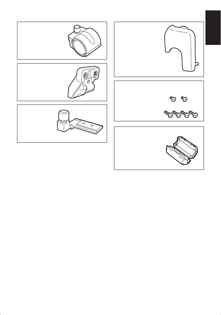
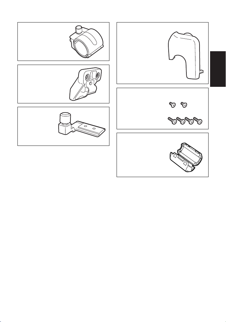
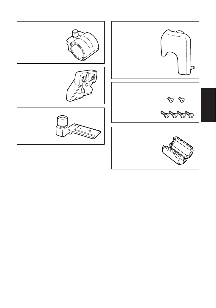
Accessories
Microphone holder
(VYC0870)
Screws
6 mm length (flush head type)
XSS3+6FZ (k2)
12 mm length
XSB4+12FZ (k4)
Mounting arm
(VYC0920)
Metal fitting
(VYQ3157)
Connector cover
(VJF1497)
Ferrite core for the microphone
(J0KG00000046)
Page 4
– 4 (E) –
12 mm
(XSB4+12FZ)
12 mm
(XSB4+12FZ)
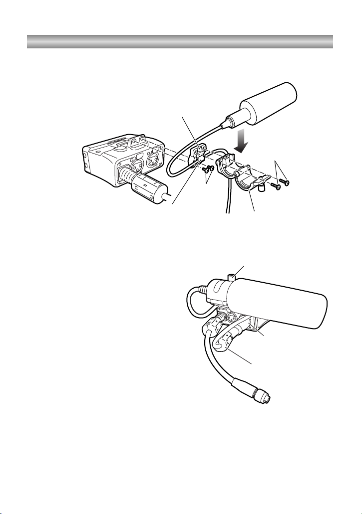
Microphone holder
Hook
3
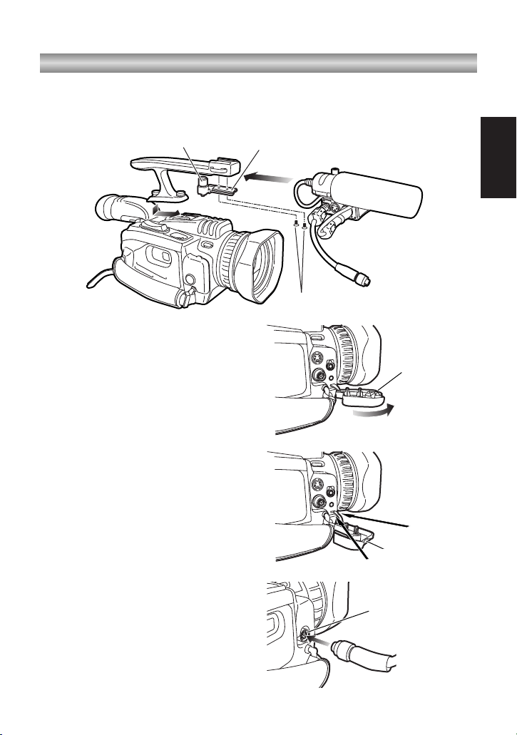
Mount the microphone on the
microphone holder, and secure it by
tightening the anchoring screws.
5
Connect the microphone’s cable to the
XLR connector on the adapter.
4
Fit the microphone’s cable into the
hook on the mounting arm.
Assembly
Attaching the microphone
Mounting arm
1
Attach the mounting arm to the adapter using the 12 mm long screws
(XSB4+12FZ).
2
Attach the microphone holder to the
mounting arm using the 12 mm long
screws (XSB4+12FZ).
XLR connector
Ferrite core for the
microphone
6
Install the accessory ferrite core for
the microphone on the XLR connector
side of the microphone’s cable.
Anchoring screws
Page 5
– 5 (E) –
ENGLISH
Assembly
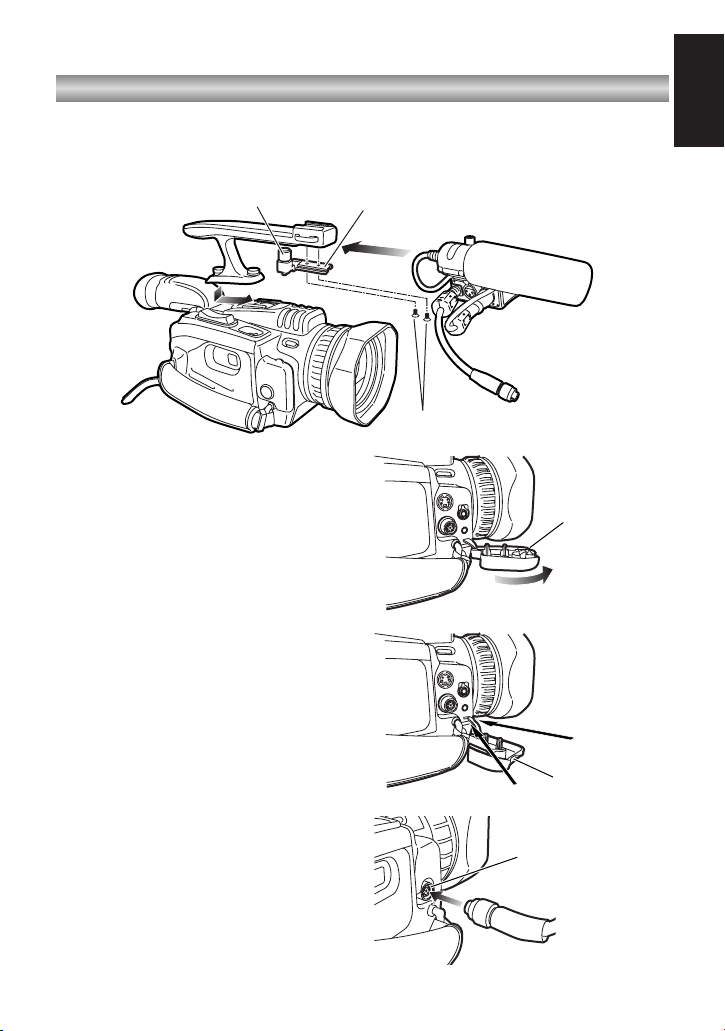
Connector cover
Connector cover
(provided)
XLR ADAPTER
connector
4
Remove the connector cover of the
AG-DVC30 (or AG-DVC32), and pull it
out in the direction indicated by the
arrow.
5
Attach the connector cover supplied
with the adapter to the AG-DVC30 (or
AG-DVC32) so that the connectors are
covered.
OAttach the connector cover by using
a thin round-tipped implement to
push it into place.
When doing this, take care not to
damage the AG-DVC30 (or AGDVC32).
6
Connect the adapter’s cable to the
XLR ADAPTER connector on the AGDVC30 (or AG-DVC32).
Mounting the adapter on the AG-DVC30 (or AG-DVC32)
3
Insert the shoe of the adapter into the
metal fitting, and secure the adapter
by tightening the anchoring screws.
2
Install the handle on the AG-DVC30
(or AG-DVC32).
1
Mount the metal fitting on the handle provided with the AG-DVC30 (or AG-DVC32)
using the 6 mm long flush-head screws (XSS3+6FZ).
Metal fittingAnchoring screws
6 mm flush head screws (XSS3+6FZ)
Page 6
– 6 (E) –
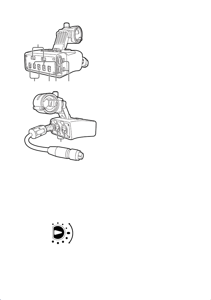
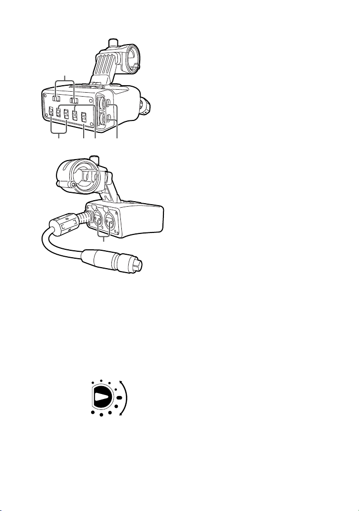
Parts and their functions
1Level control
Turn one or both of these controls to
adjust the input level of the sound.
The input levels of the CH1 (left
channel) and CH2 (right channel)
sound can be adjusted separately.
Normally, it is recommended that the
controls be kept at the center position.
2XLR connectors (INPUT1, INPUT2)
Connect a microphone or audio unit
here.
3MIC/LINE switch
Set the switch to the position
corresponding to the unit connected to
the XLR connector (INPUT1 or
INPUT2).
LINE:
Set the switch to LINE when an
audio unit has been connected to
the XLR connector.
The input level is 0 dBu.
At this point, set the wind noise
reduction function of the AG-DVC30
(or AG-DVC32) to OFF.
MIC:
Set the switch to MIC when a
microphone has been connected to
the XLR connector.
The input level can be switched
using the ATT switch 4.
4ATT switch
Use this to switch the audio input level.
ON: –50 dBu, OFF: –60 dBu
The switch setting takes effect when
the MIC/LINE switch 3 has been set
to the MIC position.
5+48V switch
When the switch is set to the ON
position, +48V power (power supply for
a phantom microphone) is supplied to
the corresponding XLR connector
(INPUT1 or INPUT2).
When connecting a unit that is not
compatible with the +48V power, set
the switch to the OFF position.
Connecting a non-compatible unit
when the switch is set to the ON
position may cause the unit to
malfunction.
Maximum
Minimum
3
1
54 6
2
OOnce the unit is mounted on the AG-
DVC30, the audio levels of the mic
input signals can no longer be adjusted
using the controls on the AG-DVC30
(or AG-DVC32).
Page 7
– 7 (E) –
ENGLISH
Specifications
Ambient operating temperature:
32°F to 104°F (0°C to +40°C)
Ambient operating humidity:
10% to 85% (no condensation)
Weight:
0.407 lb (185 g)
Excluding microphone holder
Dimensions (WkHkD):
2 3/4k1 1/2k3 inches
(69.6k36.6k75 mm)
Excluding microphone holder
XLR connector (INPUT1, INPUT2):
XLR (3 pins) k2 (CH1, CH2)
LINE/MIC switching, high impedance
LINE : 0 dBu
MIC : –50 dBu/–60 dBu (setting selected using ATT switch)
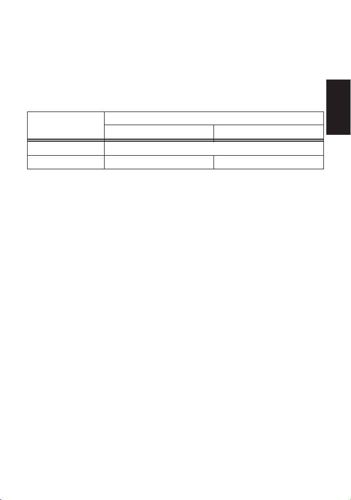
OCorrelation between CH SELECT switch positions and input signals which are
recorded on the audio tracks
CH SELECT switch
position
Audio track of the tape on which signals are recorded
CH1 CH2
CH1•2
Signals from INPUT2 connector
CH2
Signals from INPUT1 connector Signals from INPUT2 connector
6CH SELECT switch
Use this switch to select the audio
track on which to record the audio
signals that are supplied from the unit
connected to the INPUT2 connector.
OAdjusting the input level
Use the level controls 1 and ATT switch 4 to adjust the audio input level.
Adjust the level to suit the recording conditions.
Page 8
– 2 (G) –
Merkmale
Beim Modell AG-MYA30G handelt es sich um einen XLR-Mikrofonadapter, der
phantomgespeiste Mikrofone unterstützt und für den Einsatz mit dem digitalen VideoKamerarecorder AG-DVC30 entwickelt wurde.
Durch die Befestigung des Adapters am AG-DVC30 ist es möglich, den Ton von
einem XLR-Mikrofon einzugeben und Ton von hoher Qualität aufzuzeichnen.
Inhalt
Merkmale . . . . . . . . . . . . . . . . . . . . . . . 2
Zubehör . . . . . . . . . . . . . . . . . . . . . . . . 3
Montage . . . . . . . . . . . . . . . . . . . . . . . . 4
Anbringen des Mikrofons . . . . . . . . . . 4
Befestigen des Adapters am
AG-DVC30 . . . . . . . . . . . . . . . . . . . . . 5
Teile und ihre Funktionen . . . . . . . . . . 6
Technische Daten . . . . . . . . . . . . . . . . 7
ist die Sicherheitsinformation.
$ NICHT DIE ABDECKUNG ABSCHRAUBEN.
Zur Vermeidung von elektrischem Schlag darf das Gehäuse nicht
geöffnet werden. Im Geräteinneren befinden sich keine Teile, die
vom Benutzer gewartet werden können.
Wartungs- und Reparaturarbeiten grundsätzlich autorisiertem
Kundendienstpersonal überlassen.
WARNUNG:
UM BRAND- ODER STROMSCHLAGGEFAHR ZU REDUZIEREN,
MUSS DIESES GERÄT VON ALLEN FLÜSSIGKEITEN
FERNGEHALTEN WERDEN. VERMEIDEN SIE GEBRAUCH UND
LAGERUNG DES GERÄTES AN ORTEN, AN DENEN DIE GEFAHR
BESTEHT, DASS ES MIT FLÜSSIGKEITEN BETROPFT ODER
BESPRITZT WIRD, UND STELLEN SIE KEINE
FLÜSSIGKEITSBEHÄLTER AUF DAS GERÄT.
Page 9
– 3 (G) –
DEUTSCH
Zubehör
Mikrofonhalter
(VYC0870)
Schrauben
6 mm Länge (Senkschraube)
XSS3+6FZ (k2)
12 mm Länge
XSB4+12FZ (k4)
Montagearm
(VYC0920)
Metallbeschlag
(VYQ3157)
Anschlussabdeckung
(VJF1497)
Ferritkern für das Mikrofon
(J0KG00000046)
Page 10

– 4 (G) –
12 mm
(XSB4+12FZ)
12 mm
(XSB4+12FZ)
Mikrofonhalter
Haken
3
Montieren Sie das Mikrofon am
Mikrofonhalter, und sichern Sie es
durch Anziehen der Klemmschraube.
5
Schließen Sie das Mikrofonkabel an
den XLR-Anschluss des Adapters an.
4
Drücken Sie das Mikrofonkabel in den
Haken am Montagearm.
Montage
Anbringen des Mikrofons
Montagearm
1
Befestigen Sie den Montagearm mit den 12 mm langen Schrauben (XSB4+12FZ)
am Adapter.
2
Befestigen Sie den Mikrofonhalter mit
den 12 mm langen Schrauben
(XSB4+12FZ) am Montagearm.
XLR-Anschluss
Ferritkern für das Mikrofon
Klemmschraube
6
Bringen Sie den mitgelieferten
Ferritkern für das Mikrofon in der Nähe
des XLR-Anschlusses am
Mikrofonkabel an.
Page 11
– 5 (G) –
DEUTSCH
Montage
Anschlussabdeckung
Anschlussabdeckung
(mitgeliefert)
XLR ADAPTERAnschluss
4
Entfernen Sie die
Anschlussabdeckung des AG-DVC30,
und ziehen Sie sie in Pfeilrichtung
heraus.
5
Bringen Sie die mit dem Adapter
gelieferte Anschlussabdeckung so am
AG-DVC30 an, dass die Anschlüsse
geschützt sind.
ODrücken Sie die
Anschlussabdeckung mit Hilfe eines
schmalen Gegenstands mit runder
Spitze hinein.
Achten Sie dabei darauf, dass der
AG-DVC30 nicht beschädigt wird.
6
Schließen Sie das Kabel des Adapters
an den XLR ADAPTER-Anschluss des
AG-DVC30 an.
Befestigen des Adapters am AG-DVC30
3
Schieben Sie den Schuh des Adapters
auf den Metallbeschlag, und sichern
Sie den Adapter durch Anziehen der
Klemmschraube.
2
Bringen Sie den Handgriff am AGDVC30 an.
1
Befestigen Sie den Metallbeschlag mit den 6 mm langen Senkschrauben
(XSS3+6FZ) am Handgriff des AG-DVC30.
MetallbeschlagKlemmschraube
6-mm-Senkschrauben (XSS3+6FZ)
Page 12
– 6 (G) –
Teile und ihre Funktionen
1 Pegelregler
Drehen Sie einen oder beide Regler, um
den Toneingangspegel einzustellen.
Die Eingangspegel von CH1 (linker
Kanal) und CH2 (rechter Kanal) können
getrennt eingestellt werden.
Es wird empfohlen, die Regler
normalerweise in der Mittenstellung zu
belassen.
2 XLR-Anschlüsse (INPUT1, INPUT2)
Hier kann ein Mikrofon oder ein
Audiogerät angeschlossen werden.
3 Schalter MIC/LINE
Stellen Sie diese Schalter auf die
Position, die dem an den XLR-Anschluss
(INPUT1 oder INPUT2) angeschlossenen
Gerät entspricht.
LINE:
Stellen Sie den Schalter auf LINE,
wenn ein Audiogerät an den XLRAnschluss angeschlossen worden ist.
Der Eingangspegel beträgt 0 dBu.
Setzen Sie an dieser Stelle die
Windgeräuschreduzierung des AGDVC30 auf OFF.
MIC:
Stellen Sie den Schalter auf MIC,
wenn ein Mikrofon an den XLRAnschluss angeschlossen worden ist.
Der Eingangspegel kann mit Hilfe des
Schalters ATT 4 umgeschaltet
werden.
4 Schalter ATT
Dieser Schalter dient zum Umschalten
des Audio-Eingangspegels.
ON: –50 dBu, OFF: –60 dBu
Die Schaltereinstellung wird wirksam,
wenn der Schalter MIC/LINE 3 auf die
Position MIC gestellt worden ist.
5 Schalter +48V
In der Schalterstellung ON wird ein Strom
von +48 V (Phantomspeisung für
Mikrofon) dem entsprechenden XLRAnschluss (INPUT1 oder INPUT2)
zugeführt.
Wenn Sie ein Gerät anschließen, das
nicht mit der +48-V-Spannung kompatibel
ist, stellen Sie den Schalter auf die
Position OFF.
Wird ein nicht kompatibles Gerät in der
Schalterstellung ON angeschlossen,
kann es zu einer Funktionsstörung des
Geräts kommen.
Maximum
Minimum
3
1
54 6
2
O Nachdem die Einheit am AG-DVC30
montiert worden ist, kann der Audiopegel
der Mikrofon-Eingangssignale nicht mehr
mit den Reglern am AG-DVC30
eingestellt werden.
Page 13
– 7 (G) –
DEUTSCH
Technische Daten
Betriebstemperatur:
0°C bis +40°C
Betriebsluftfeuchtigkeit:
10% bis 85% (keine Kondensation)
Gewicht:
185 g
Ohne Mikrofonhalter
Abmessungen (BkHkT):
69,6k36,6k75 mm
Ohne Mikrofonhalter
XLR-Anschlüsse (INPUT1, INPUT2):
XLR (3-polig) k2 (CH1, CH2)
LINE/MIC-Umschaltung, hochohmig
LINE : 0 dBu
MIC : –50 dBu/–60 dBu (Einstellungswahl mit Schalter ATT)
OBeziehung zwischen den Positionen des Schalters CH SELECT und den auf
die Tonspuren aufgezeichneten Eingangssignalen
Position des
Schalters CH SELECT
Tonspur des Bands, auf das die Signale aufgezeichnet werden
CH1 CH2
CH1•2
Signale vom Anschluss INPUT2
CH2
Signale vom Anschluss INPUT1 Signale vom Anschluss INPUT2
6 Schalter CH SELECT
Benutzen Sie diesen Schalter zur Wahl
der Tonspur, auf welche die Audiosignale
aufgezeichnet werden sollen, die von
dem an den Anschluss INPUT2
angeschlossenen Gerät zugeführt
werden.
OEinstellen des Eingangspegels
Verwenden Sie die Pegelregler 1 und den Schalter ATT 4 zum Einstellen des
Audio-Eingangspegels.
Passen Sie den Pegel den Aufnahmebedingungen an.
Page 14
– 2 (F) –
Caractéristiques
L’AG-MYA30G est un modèle d’adaptateur de microphone XLR qui supporte un
microphone fantôme et qui a été spécialement conçu pour le camescope numérique
AG-DVC30.
La fixation de l’adaptateur sur l’AG-DVC30 permet de recevoir le son d’un microphone
XLR et de l’enregistrer avec un haut niveau de qualité.
Table des matières
Caractéristiques. . . . . . . . . . . . . . . . . . 2
Accessoires . . . . . . . . . . . . . . . . . . . . . 3
Montage . . . . . . . . . . . . . . . . . . . . . . . . 4
Fixation du microphone . . . . . . . . . . . 4
Fixation de l’adaptateur sur
l’AG-DVC30 . . . . . . . . . . . . . . . . . . . . 5
Les commandes et leurs fonctions . . 6
Fiche technique . . . . . . . . . . . . . . . . . . 7
Informations concernant la sécurité.
$ NE PAS RETIRER LE COUVERCLE EN LE DÉVISSANT.
Pour réduire tout risque d’électrocution, ne pas retirer le couvercle. Il
ne se trouve à l’intérieur aucune pièce qui puisse être réparée par
l’utilisateur.
Confier toute réparation à un personnel qualifié.
AVERTISSEMENT:
POUR RÉDUIRE TOUT RISQUE DE FEU OU DE CHOC
ÉLECTRIQUE, ÉLOIGNER L’APPAREIL DES LIQUIDES - UTILISER
ET RANGER UNIQUEMENT DANS UN ENDROIT NE RISQUANT PAS
DE RECEVOIR DES GOUTTES OU D’ÊTRE ASPERGÉ DE
LIQUIDES, ET NE PAS METTRE DE RÉCIPIENT RENFERMANT DES
LIQUIDES SUR LE DESSUS DE L’APPAREIL.
Page 15
– 3 (F) –
FRANÇAIS
Accessoires
Support de microphone
(VYC0870)
Vis
6 mm de long (à tête noyée)
XSS3+6FZ (k2)
12 mm de long
XSB4+12FZ (k4)
Bras de montage
(VYC0920)
Armature métallique
(VYQ3157)
Cache des connecteurs
(VJF1497)
Tore de ferrite pour le microphone
(J0KG00000046)
Page 16

– 4 (F) –
12 mm
(XSB4+12FZ)
12 mm
(XSB4+12FZ)
Support de microphone
Crochet
3
Monter le microphone sur le support
de microphone, et le fixer en serrant
les vis d’ancrage.
5
Raccorder le câble du microphone au
connecteur XLR de l’adaptateur.
4
Faire passer le câble du microphone
dans le crochet du bras de montage.
Montage
Fixation du microphone
Bras de montage
1
Fixer le bras de montage sur l’adaptateur à l’aide des vis de 12 mm de long
(XSB4+12FZ).
2
Fixer le support de microphone au
bras de montage à l’aide des vis de 12
mm de long (XSB4+12FZ).
Connecteur XLR
Tore de ferrite pour le
microphone
Vis d’ancrage
6
Installer le tore de ferrite accessoire
pour le microphone sur le côté du
connecteur XLR du câble du
microphone.
Page 17

– 5 (F) –
FRANÇAIS
Montage
Cache des
connecteurs
Cache des
connecteurs (fourni)
Connecteur XLR
ADAPTER
4
Retirer le cache des connecteurs de
l’AG-DVC30, et tirer dessus dans le
sens de la flèche.
5
Fixer le cache des connecteurs fourni
avec l’adaptateur sur l’AG-DVC30 de
façon à recouvrir les connecteurs.
OFixer le cache des connecteurs à
l’aide d’un instrument à bout rond et
fin pour le pousser en place.
Pendant cette opération, veiller à ne
pas endommager l’AG-DVC30.
6
Raccorder le câble de l’adaptateur au
connecteur XLR ADAPTER de l’AGDVC30.
Fixation de l’adaptateur sur l’AG-DVC3O
3
Insérer la griffe de l’adaptateur dans
l’armature métallique, et fixer
l’adaptateur en serrant les vis
d’ancrage.
2
Fixer la poignée sur l’AG-DVC30.
1
Monter l’armature métallique de la poignée fournie avec l’AG-DVC30 à l’aide des
vis à tête noyée de 6 mm de long (XSS3+6FZ).
Armature métalliqueVis d’ancrage
Vis à tête noyée de 6 mm de long (XSS3+6FZ)
Page 18

– 6 (F) –
Les commandes et leurs fonctions
1 Commande de niveau
Tourner l’une de ces commandes ou les
deux pour régler le niveau d’entrée du
son.
Les niveaux d’entrée du canal 1 (gauche)
et du canal 2 (droit) se règlent
séparément.
Normalement, il est recommandé de
laisser ces commandes sur leur position
centrale.
2 Connecteurs XLR (INPUT1, INPUT2)
Y raccorder un microphone ou un
appareil audio.
3 Commutateur de microphone/ligne
(MIC/LINE)
Mettre ce commutateur sur la position
correspondant à l’appareil raccordé au
connecteur XLR (INPUT1 ou INPUT2).
LINE:
Mettre le commutateur sur LINE si l’on
raccorde un appareil audio au
connecteur XLR.
Le niveau d’entrée est de 0 dBu.
À ce moment, régler la fonction de
réduction du bruit du vent de l’AGDVC30 sur OFF.
MIC:
Mettre le commutateur sur MIC si l’on
raccorde un microphone au
connecteur XLR.
Le niveau d’entrée se règle avec le
commutateur ATT 4.
4 Commutateur d’atténuation (ATT)
Utiliser ce commutateur pour régler le
niveau d’entrée audio.
ON: –50 dBu, OFF: –60 dBu
Le réglage du commutateur entre en
vigueur quand on règle le commutateur
MIC/LINE 3 sur la position MIC.
5 Commutateur +48V
Quand ce commutateur est sur la position
ON, une alimentation de +48 V
(alimentation pour un microphone
fantôme) est fournie au connecteur XLR
correspondant (INPUT1 ou INPUT2).
Si l’on raccorde un appareil non
compatible avec l’alimentation de +48 V,
mettre ce commutateur sur la position
OFF.
Le raccordement d’un appareil non
compatible avec ce connecteur sur la
position ON peut provoquer un
dysfonctionnement de l’appareil.
Maximum
Minimum
3
1
54 6
2
O Un fois que l’appareil est monté sur l’AG-
DVC30, il n’est plus possible de régler les
niveaux audio des signaux d’entrée du
microphone avec les commandes de
l’AG-DVC30.
Page 19

– 7 (F) –
FRANÇAIS
Fiche technique
Température de fonctionnement ambiante:
0°C à +40°C
Humidité de fonctionnement ambiante:
10% à 85% (pas de condensation)
Poids:
185 g
Sans le support de microphone
Dimensions (LkHkP):
69,6k36,6k75 mm
Sans le support de microphone
Connecteur XLR (INPUT1, INPUT2):
XLR (3 broches) k2 (CH1, CH2)
LINE/MIC commutable, haute impédance
LINE : 0 dBu
MIC : –50 dBu/–60 dBu (paramètre sélectionné avec le commutateur ATT)
ORelation entre la position du sélecteur CH SELECT et les signaux d’entrée qui
s’enregistrent sur les pistes audio
Position du sélecteur
CH SELECT
Piste audio de la bande sur laquelle les signaux s’enregistrent
CH1 CH2
CH1•2
Signaux du connecteur INPUT2
CH2
Signaux du connecteur INPUT1 Signaux du connecteur INPUT2
6 Sélecteur de canal (CH SELECT)
Utiliser ce sélecteur pour sélectionner la
piste audio sur laquelle enregistrer les
signaux audio envoyés par l’appareil
raccordé au connecteur INPUT2.
ORéglage du niveau d’entrée
Utiliser les commandes de niveau 1 et le commutateur ATT 4 pour régler le
niveau d’entrée audio.
Réglez le niveau en fonction des conditions d’enregistrement.
Page 20

– 2 ( I ) –
Caratteristiche
Il modello AG-MYA30G è un adattatore per microfono che supporta un microfono
virtuale, e che è stato sviluppato per essere usato con la videocamera digitale AGDVC30.
Il montaggio dell’adattatore sulla AG-DVC30 permette di alimentare il suono da un
microfono XLR e di registrarlo con un’alta qualità.
Sommario
Caratteristiche . . . . . . . . . . . . . . . . . . . 2
Accessori . . . . . . . . . . . . . . . . . . . . . . . 3
Montaggio. . . . . . . . . . . . . . . . . . . . . . . 4
Modo di attaccare il microfono . . . . . . 4
Montaggio dell’adattatore sulla
AG-DVC30 . . . . . . . . . . . . . . . . . . . . . 5
Parti e loro funzioni . . . . . . . . . . . . . . . 6
Dati tecnici . . . . . . . . . . . . . . . . . . . . . . 7
sono le informazioni sulla sicurezza.
$ NON RIMUOVERE IL COPERCHIO SVITANDOLO.
Per ridurre i pericoli di scosse elettriche, non togliere il coperchio.
All’interno non ci sono parti riparabili dall’utente.
Per le riparazioni, rivolgersi a personale tecnico qualificato.
ATTENZIONE:
PER RIDURRE IL RISCHIO D’INCENDIO O DI SCOSSE
ELETTRICHE, TENERE QUESTO PRODOTTO LONTANO DA TUTTI I
LIQUIDI. USARLO E CONSERVARLO SOLTANTO IN LUOGHI CHE
NON SIANO ESPOSTI A GOCCIOLAMENTI O SPRUZZI DI LIQUIDI,
E NON METTERVI SOPRA RECIPIENTI DI LIQUIDI.
Page 21

– 3 ( I ) –
ITALIANO
Accessori
Supporto microfono
(VYC0870)
Viti
Lunghezza 6 mm
(tipo con testa piatta)
XSS3+6FZ (k2)
Lunghezza 12 mm
XSB4+12FZ (k4)
Braccio di montaggio
(VYC0920)
Accessorio metallico
(VYQ3157)
Coperchio connettore
(VJF1497)
Nucleo in ferrite per microfono
(J0KG00000046)
Page 22

– 4 ( I ) –
12 mm
(XSB4+12FZ)
12 mm
(XSB4+12FZ)
Supporto microfono
Gancio
3
Montare il microfono sul supporto
microfono, e fissarlo stringendo le viti
di ancoraggio.
5
Collegare il cavo del microfono al
connettore XLR dell’adattatore.
4
Inserire il cavo del microfono nel
gancio del braccio di montaggio.
Montaggio
Modo di attaccare il microfono
Braccio di montaggio
1
Attaccare il braccio di montaggio all’adattatore usando le viti di 12 mm di lunghezza
(XSB4+12FZ).
2
Attaccare il supporto microfono al
braccio di montaggio usando le viti di
12 mm di lunghezza (XSB4+12FZ).
Connettore XLR
Nucleo in ferrite per
microfono
Viti di ancoraggio
6
Installare il nucleo in ferrite per
microfono accessorio sul lato del
connettore XLR del cavo del
microfono.
Page 23

– 5(I) –
ITALIANO
Montaggio
Coperchio
connettore
Coperchio
connettore
(in dotazione)
Connettore XLR
ADAPTER
4
Rimuovere il coperchio connettore
della AG-DVC30, e tirarlo fuori nella
direzione indicata dalla freccia.
5
Attaccare alla AG-DVC30 il coperchio
connettore in dotazione all’adattatore,
in modo che i connettori siano coperti.
OAttaccare il coperchio connettore
usando un oggetto sottile con punta
arrotondata per spingerlo in
posizione.
Facendo ciò, stare attenti a non
danneggiare la AG-DVC30.
6
Collegare il cavo dell’adattatore al
connettore XLR ADAPTER della AGDVC30.
Montaggio dell’adattatore sulla AG-DVC30
3
Inserire la slitta dell’adattatore
nell’accessorio metallico, e fissare
l’adattatore stringendo le viti di
ancoraggio.
2
Installare il manico sulla AG-DVC30.
1
Montare l’accessorio metallico sul manico della AG-DVC30 usando le viti di 6 mm
con testa piatta (XSS3+6FZ).
Accessorio metallicoViti di ancoraggio
Viti di 6 mm di lunghezza con testa piatta
(XSS3+6FZ)
Page 24

– 6(I) –
Parti e loro funzioni
1 Controllo di livello
Girare uno o entrambi questi controlli per
regolare il livello d’ingresso del suono.
I livelli d’ingresso del suono CH1 (canale
sinistro) e CH2 (canale destro) possono
essere regolati separatamente.
Si consiglia di lasciare normalmente i
controlli sulla loro posizione centrale.
2 Connettori XLR (INPUT1, INPUT2)
Collegare qui un microfono o unità audio.
3 Interruttore MIC/LINE
Regolare l’interruttore sulla posizione
corrispondente all’unità collegata al
connettore XLR (INPUT1 o INPUT2).
LINE:
Posizionare l’interruttore su LINE se al
connettore XLR si è collegata una
unità audio.
Il livello d’ingresso è di 0 dBu.
A questo punto, disattivare la funzione
di riduzione del rumore dell’AGDVC30.
MIC:
Posizionare l’interruttore su MIC se al
connettore XLR si è collegato un
microfono.
Il livello d’ingresso può essere
cambiato usando l’interruttore ATT 4.
4 Interruttore ATT
Usare questo interruttore per cambiare il
livello d’ingresso audio.
ON: –50 dBu, OFF: –60 dBu
La regolazione dell’interruttore diventa
effettiva quando si si posiziona
l’interruttore MIC/LINE 3 su MIC.
5 Interruttore +48V
Quando si regola l’interruttore sulla
posizione ON, al connettore XLR
(INPUT1 o INPUT2) corrispondente viene
alimentata una corrente di +48V (corrente
per il microfono virtuale).
Se si collega una unità che non è
compatibile con la corrente di +48V,
posizionare l’interruttore su OFF.
Se con l’interruttore posizionato su ON si
collega una unità che non è compatibile,
l’unità potrebbe malfunzionare.
Massimo
Minimo
3
1
54 6
2
O Una volta montata l’unità sulla AG-
DVC30, i livelli audio dei segnali
d’ingresso del microfono non possono più
essere regolati usando i controlli della
AG-DVC30.
Page 25

– 7(I) –
ITALIANO
Dati tecnici
Temperatura d’esercizio:
Da 0°C a +40°C
Umidità permissibile:
Da 10% a 85% (senza condensa)
Peso:
185 g
Supporto microfono escluso
Dimensioni (LkAkP):
69,6k36,6k75 mm
Supporto microfono escluso
Connettore XLR (INPUT1, INPUT2):
XLR (3 pin) k2 (CH1, CH2)
Selezione LINE/MIC, alta impedenza
LINE : 0 dBu
MIC : –50 dBu/–60 dBu (regolazione selezionata con l’interruttore ATT)
ORapporto tra le posizioni di CH SELECT e i segnali d’ingresso registrati sulle
piste audio
Posizione interruttore
CH SELECT
Pista audio del nastro su cui vengono registrati i segnali
CH1 CH2
CH1•2
Segnali dal connettore INPUT2
CH2
Segnali dal connettore INPUT1 Segnali dal connettore INPUT2
6 Interruttore CH SELECT
Usare questo interruttore per selezionare
la pista audio su cui registrare i segnali
audio alimentati dall’unità collegata al
connettore INPUT2.
ORegolazione del livello d’ingresso
Usare i controlli di livello 1 e l’interruttore ATT 4 per regolare il livello d’ingresso
audio.
Regolare il livello adatto alle condizioni di registrazione.
Page 26

– 2 (S) –
Características
El modelo AG-MYA30G es un adaptador de micrófono XLR que sirve de apoyo a un
micrófono fantasma y que fue desarrollado para ser utilizado con la videocámaragrabadora digital AG-DVC30.
Al montar el adaptador en la AG-DVC30 se puede introducir sonido desde el
micrófono XLR y grabar sonido con una calidad alta.
Índice
Características. . . . . . . . . . . . . . . . . . . 2
Accesorios . . . . . . . . . . . . . . . . . . . . . . 3
Montaje . . . . . . . . . . . . . . . . . . . . . . . . . 4
Colocación del micrófono. . . . . . . . . . 4
Montaje del adaptador en la
AG-DVC30 . . . . . . . . . . . . . . . . . . . . . 5
Partes y sus funciones . . . . . . . . . . . . 6
Especificaciones . . . . . . . . . . . . . . . . . 7
indica información de seguridad.
$ NO QUITE LA TAPA DESATORNILLÁNDOLA.
No quite la tapa para evitar el riesgo de sacudidas eléctricas. Las
piezas del interior no requieren mantenimiento por parte del usuario.
Solicite las reparaciones al personal de servicio calificado.
ADVERTENCIA:
PARA REDUCIR EL RIESGO DE INCENDIO O SACUDIDA
ELÉCTRICA, MANTENGA ESTE EQUIPO ALEJADO DE TODOS LOS
LÍQUIDOS. UTILÍCELO Y GUÁRDELO SOLAMENTE EN LUGARES
DONDE NO CORRA EL RIESGO DE QUE LE CAIGAN GOTAS O LE
SALPIQUEN LÍQUIDOS, Y NO COLOQUE NINGÚN RECIPIENTE DE
LÍQUIDOS ENCIMA DEL EQUIPO.
Page 27

– 3 (S) –
ESPAÑOL
Accesorios
Portamicrófono
(VYC0870)
Tornillos
6 mm de longitud
(tipo de cabeza plana)
XSS3+6FZ (k2)
12 mm de longitud
XSB4+12FZ (k4)
Brazo de montaje
(VYC0920)
Accesorio metálico
(VYQ3157)
Cubierta de conectores
(VJF1497)
Núcleo de ferrita para el micrófono
(J0KG00000046)
Page 28

– 4 (S) –
12 mm
(XSB4+12FZ)
12 mm
(XSB4+12FZ)
Portamicrófono
Gancho
3
Monte el micrófono en el
portamicrófono y asegúrelo apretando
los tornillos de anclaje.
5
Conecte el cable del micrófono en el
conector XLR del adaptador.
4
Fije el cable del micrófono en el
gancho del brazo de montaje.
Montaje
Colocación del micrófono
Brazo de montaje
1
Coloque el brazo de montaje en el adaptador utilizando los tornillos de 12 mm de
longitud (XSB4+12FZ).
2
Coloque el portamicrófono en el brazo
de montaje utilizando los tornillos de
12 mm de longitud (XSB4+12FZ).
Conector XLR
Núcleo de ferrita para el
micrófono
Tornillos de anclaje
6
Instale el núcleo de ferrita
suministrado para el micrófono en el
lado del conector XLR del cable del
micrófono.
Page 29

– 5 (S) –
ESPAÑOL
Montaje
Cubierta de
conectores
Cubierta de
conectores
(suministrada)
Conector XLR
ADAPTER
4
Quite la cubierta de conectores de la
AG-DVC30 sacándola en el sentido
indicado por la flecha.
5
Coloque la cubierta de conectores
suministrada con el adaptador en la
AG-DVC30 de forma que los
conectores queden tapados.
OColoque la cubierta de conectores
utilizando una herramienta de punta
redonda y fina para empujar y
colocar la cubierta en su lugar.
Cuando haga esto, tenga cuidado
para no estropear la AG-DVC30.
6
Conecte el cable del adaptador en el
conector XLR ADAPTER de la AGDVC30.
Montaje del adaptador en la AG-DVC30
3
Introduzca la zapata del adaptador en
el accesorio metálico, y asegure el
adaptador apretando los tornillos de
anclaje.
2
Instale el asa en la AG-DVC30.
1
Monte el accesorio metálico en el asa suministrada con la AG-DVC30 utilizando los
tornillos de cabeza plana de 6 mm de longitud (XSS3+6FZ).
Accesorio metálicoTornillos de anclaje
Tornillos de cabeza plana de 6 mm
(XSS3+6FZ)
Page 30

– 6 (S) –
Partes y sus funciones
1 Controles de nivel
Gire uno de estos controles, o ambos,
para ajustar el nivel de entrada del
sonido.
Los niveles de entrada del sonido de
CH1 (canal izquierdo) y CH2 (canal
derecho) pueden ajustarse
separadamente.
Normalmente se recomienda mantener
los controles en las posiciones centrales.
2 Conectores XLR (INPUT1, INPUT2)
Conecte aquí un micrófono o unidad de
audio.
3 Conmutador MIC/LINE
Ponga este conmutador en la posición
correspondiente a la unidad conectada al
conector XLR (INPUT1 o INPUT2).
LINE:
Ponga el conmutador en LINE cuando
se haya conectado una unidad de
audio al conector XLR.
El nivel de entrada es 0 dBu.
Ahora, desactive la función de
reducción del ruido del viento de la
AG-DVC30.
MIC:
Ponga el conmutador en MIC cuando
se haya conectado un micrófono al
conector XLR.
El nivel de entrada se puede cambiar
utilizando el conmutador ATT 4.
4 Conmutador ATT
Utilícelo para cambiar el nivel de entrada
de audio.
ON: –50 dBu, OFF: –60 dBu
El ajuste del conmutador se activa
cuando el conmutador MIC/LINE 3 se ha
puesto en la posición MIC.
5 Conmutador +48V
Cuando este conmutador se ponga en la
posición ON se suministrará una potencia
de +48 V (para un micrófono fantasma) al
conector XLR correspondiente (INPUT1 o
INPUT2).
Cuando se conecte una unidad que no
sea compatible con la potencia de +48 V,
ponga el conmutador en la posición OFF.
La conexión de una unidad incompatible
cuando el conmutador está en la posición
ON puede causar un fallo en el
funcionamiento de la unidad.
Máximo
Mínimo
3
1
54 6
2
O Una vez montada la unidad en la AG-
DVC30, los niveles de audio de las
señales de entrada del micrófono no
pueden ajustarse más utilizando los
controles de la AG-DVC30.
Page 31

– 7 (S) –
ESPAÑOL
Especificaciones
Temperatura ambiental de funcionamiento:
0°C a +40°C
Humedad ambiental de funcionamiento:
10% a 85% (sin condensación)
Peso:
185 g
Excluyendo el portamicrófono
Dimensiones (AnkAlkProf):
69,6k36,6k75 mm
Excluyendo el portamicrófono
Conector XLR (INPUT1, INPUT2):
XLR (3 contactos) k2 (CH1, CH2)
Conmutación LINE/MIC, alta impedancia
LINE : 0 dBu
MIC : –50 dBu/–60 dBu (ajuste seleccionado utilizando el conmutador ATT)
OCorrelación entre las posiciones del conmutador CH SELECT y las señales de
entrada que se van a grabar en las pistas de audio.
Posición del
conmutador CH
SELECT
Pista de audio de la cinta en la que se van a grabar señales
CH1 CH2
CH1•2
Señales procedentes del conector INPUT2
CH2
Señales procedentes del conector
INPUT1
Señales procedentes del conector
INPUT2
6 Conmutador CH SELECT
Utilice este conmutador para seleccionar
la pista de audio en la que se van a
grabar las señales de audio
suministradas desde la unidad conectada
al conector INPUT2.
OAjuste del nivel de entrada
Utilice los controles de nivel 1 y el conmutador ATT 4 para ajustar el nivel de
entrada de audio.
Ajuste el nivel según las condiciones de grabación.
Page 32

– 2 (C) –
AG-MYA30G XLR
AG-DVC33
AG-DVC33 XLR
. . . . . . . . . . . . . . . . . . . . . . . . 2
. . . . . . . . . . . . . . . . . . . . . . . . 3
. . . . . . . . . . . . . . . . . . . . . . . . 4
. . . . . . . . . . . . . . . . . 4
AG-DVC33 . . . . 5
. . . . . . . . . . . . . . . . . 6
. . . . . . . . . . . . . . . . . . . . . . . . 7
$
Page 33

– 3 (C) –
(VYC0870)
6 mm
XSS3+6FZ (k2)
12 mm
XSB4+12FZ (k4)
(VYC0920)
(VYQ3157)
(VJF1497)
(J0KG00000046)
Page 34

– 4 (C) –
12 mm
(XSB4+12FZ)
12 mm
(XSB4+12FZ)
3
5
XLR
4
1
12 mm (XSB4+12FZ)
2
12 mm (XSB4+12FZ)
XLR
6
XLR
Page 35

– 5 (C) –
XLR ADAPTER
4
AG-DVC33
5
AG-DVC33
O
AG-
DVC33
6
AG-DVC33
XLR ADAPTER
AG-DVC33
3
2
AG-DVC33
1
6 mm (XSS3+6FZ) AG-DVC33
6 mm (XSS3+6FZ)
Page 36

– 6 (C) –
1
CH1 CH2
2XLR (INPUT1 INPUT2)
3MIC/LINE
XLR
INPUT1 INPUT2
LINE
XLR
LINE
0 dBu
AG-DVC33
OFF
MIC
XLR
MIC
ATT 4
4ATT
ON: –50 dBu, OFF: –60 dBu
MIC/LINE 3 MIC
ATT
5+48V
ON
+48 V
XLR INPUT1
INPUT2
+48 V
OFF
ON
+48 V
3
1
54 6
2
O AG-DVC33
AG-DVC33
Page 37

– 7 (C) –
0°C +40°C
10
85
185 g
69.6 36.6 75 mm
XLR (INPUT1 INPUT2)
XLR 3 2 CH1 CH2
LINE/MIC
LINE : 0 dBu
MIC : –50 dBu/–60 dBu
ATT
O CH SELECT
CH SELECT
CH1 CH2
CH1•2
INPUT2
CH2
INPUT1
INPUT2
6CH SELECT
INPUT2
O
1 ATT 4
Page 38

– 2 (J) –
目 次
安全上のご注意 .................2
特長..........................5
付属品 ........................5
組み立て ......................6
マイクを取り付ける ............6
AG-DVC30 に取り付ける .......7
各部の名称と機能................8
定 格 ........................9
保証とアフターサービス .........10
保証書別添付
保証書は、「お買い上げ日・販売店名」などの記入を必ず確かめ、販売店からお受け
取りください。
安全上のご注意
必ずお守りください
お使いになる人や他の人への危害、財産への損害を未然に防止するため、必ずお守り
いただくことを、次のように説明しています。
■ 表示内容を無視して誤った使い方をしたときに生じる危害や損害の程度を、次の表
示で区分し、説明しています。
■ お守りいただく内容の種類を、次の絵表示で区分し、説明しています。
(下記は、絵表示の一例です。)
この表示の欄は、「死亡または重傷などを負う可能性が想定
される」内容です。
この表示の欄は、「傷害を負う可能性または物的損害のみが
発生する可能性が想定される」内容です。
警告
注意
このような絵表示は、気をつけていただきたい「注意喚起」
内容です。
このような絵表示は、してはいけない「禁止」内容です。
このような絵表示は、必ず実行していただく「強制」内容
です。
Page 39

– 3 (J) –
日
本
語
安全上のご注意
必ずお守りください
接続コードに重いものを載せな
い!
本機の下敷きにならない
よう注意してください。
コードが傷ついて、火災
や感電の原因になりま
す。
禁 止
本機を改造しない!
火災や感電の原因になり
ます。
分解禁止
警告
接続コード・プラグが破損する
ようなことはしない!
傷つけたり、加工したり、高温
部に近づけたり、無理に曲げた
り、ねじったり、引っ張ったり、
重いものを載せたり、束ねたり
しない!
傷んだまま使用すると、
感電・ショート・火災の
原因になります。
O
コードやプラグの修理は、お買い上
げの販売店にご相談ください。
禁 止
煙が出ている、変なにおいや音
がするなどの異常状態の場合
は、電源を切り、接続コードを
抜く!
O
お買い上げの販売店に修理を依頼し
てください。
そのまま使用すると、
火災や感電の原因にな
ります。
接続コード
を抜く
本機を落としたり破損した場合
や、
内部に異物や水などが入っ
た場合は、電源を切り、接続コ
ードを抜く!
O
お買い上げの販売店にご相談くださ
い。
そのまま使用すると、
火災や感電の原因にな
ります。
接続コード
を抜く
Page 40

– 4 (J) –
機器が濡れたり、水が入らない
ようにする!
火災や感電の原因になり
ます。
雨天・降雪・海岸・水辺
での使用は、特にご注意
ください。
接続コードが傷んだ場合は、交
換を依頼する!
O
お買い上げの販売店にご相談くださ
い。
そのまま使用すると、火
災や感電の原因になりま
す。
安全上のご注意
必ずお守りください
警告
注意
油煙や湯気、湿気やほこりの多
い場所に置かない!
火災や感電の原因になる
恐れがあります。
禁 止
ぬれた手でプラグやコネクター
に触れない!
感電の原因になる恐れが
あります。
禁 止
プラグやコネクターを抜くとき
は、コードを引っ張らない!
O
必ずプラグやコネクターを持って抜
いてください。
コードが傷つき、火災や
感電の原因になる恐れが
あります。
禁 止
Page 41

– 5 (J) –
日
本
語
特 長
本機は、デジタルビデオカメラレコーダー AG-DVC30 用に開発された、ファントム
マイク対応の XLR マイクアダプターです。
AG-DVC30 に本機を取り付けると、XLR マイクからの音声を入力することができ、
ハイクオリティな音声を収録することができます。
付属品
マイクホルダー
(VYC0870)
ネジ
長さ 6mm(皿ネジ)
(XSS3+6FZ)2 本
長さ 12mm
(XSB4+12FZ)4 本
取り付けアーム
(VYC0920)
固定金具
(VYQ3157)
マイク用フェライトコア
(J0KG00000046)
端子カバー
(VJF1497)
Page 42

– 6 (J) –
12 mm
(XSB4+12FZ)
12 mm
(XSB4+12FZ)
マイクホルダー
XLR 端子
マイク用フェライトコア
フック
3
マイクホルダーにマイクを取り付け、
固定ネジを締めてマイクを固定しま
す。
5
マイクのケーブルをアダプター本体の
XLR 端子に接続します。
6
付属のマイク用フェライトコアをマイ
クケーブルの XLR 端子側に取り付け
ます。
4
取り付けアームのフックにマイクのケ
ーブルをはめ込みます。
固定ネジ
組み立て
マイクを取り付ける
取り付けアーム
1
取り付けアームを長さ 12 mm のネジ(XSB4+12FZ)で、アダプター本体に取
り付けます。
2
マイクホルダーを長さ 12mm のネジ
(XSB4+12FZ)で、取り付けアーム
に取り付けます。
Page 43

– 7 (J) –
日
本
語
組み立て
端子カバー
端子カバー
(付属)
XLRADAPTER 端子
4
AG-DVC30 の端子カバーをはがし、
矢印の方向に引き抜きます。
5
付属の端子カバーを AG-DVC30 に取
り付け、端子部にかぶせます。
O
端子カバーは、先が丸くて細い物
で押し込んで取り付けます。
このとき AG-DVC30 を傷つけな
いように注意してください。
6
アダプター本体のケーブルを AGDVC30 の XLRADAPTER 端子に接
続します。
AG-DVC30 に取り付ける
3
アダプター本体のシューを固定金具に
差し込み、固定ネジを締めてアダプタ
ー本体を固定します。
2
AG-DVC30 にハンドルを取り付けま
す。
1
固定金具を長さ 6 mm の皿ネジ(XSS3+6FZ)で、AG-DVC30 に付属されて
いるハンドルに取り付けます。
固定金具固定ネジ
6mm(皿ネジ)XSS3+6FZ
Page 44

– 8 (J) –
各部の名称と機能
1
レベル調整ダイヤル
ダイヤルを回して音声の入力レベルを
調整します。
CH1(Lch)と CH2(Rch)の入力
音声を別々に調整することができま
す。
通常は、センター位置で使用すること
をお薦めします。
O
AG-DVC30 に本機を取り付けると、
AG-DVC30 側でマイク入力の音声レ
ベルを調整することができなくなりま
す。
2
XLR 端子(INPUT1、INPUT2)
マイクやオーディオ機器を接続しま
す。
3
MIC/LINE スイッチ
XLR 端子(INPUT1 または INPUT2)
に接続する機器に合わせて、スイッチ
を切り替えます。
LINE :
オーディオ機器を XLR 端子に接続
したときは、LINE の位置にします。
入力レベルは、0dBu です。
このとき、AG-DVC30 のウィンド
ノイズリダクションの機能を「切」
にしてください。
MIC :
マイクを XLR 端子に接続したとき
は、MIC の位置にします。
入力レベルは、ATT スイッチ4で
切り替えることができます。
4
ATT スイッチ
音声の入力レベルを切り替えます。
ON :− 50dBu
OFF:− 60dBu
MIC/LINE スイッチ3が、MIC の位
置のときに有効になります。
5
+ 48V スイッチ
ON の位置にすると、XLR 端子
(INPUT1 または INPUT2)に
+ 48V 電源(ファントムマイク用の
電源)を供給します。
+ 48V 電源に対応していない機器を
接続するときは、OFF の位置にして
ください。
ON の位置にして+ 48V 電源に対応
していない機器を使用すると、接続し
た機器が故障する場合があります。
最大
最小
3
1
54 6
2
Page 45

– 9 (J) –
日
本
語
O
入力レベルの調整
音声の入力レベルは、レベル調整ダイヤル1と ATT スイッチ4で調整します。
記録する状況に応じて、調整してください。
定 格
動作周囲温度:
0 ℃〜+ 40 ℃
動作周囲湿度:
10%〜 85%(結露なし)
質量:
185g(マイクホルダーを含まない)
外形寸法(幅×高さ×奥行き):
69.6 × 36.6 × 75
mm
(マイクホルダーを含まない)
XLR 端子(INPUT1、INPUT2):
XLR(3 ピン)× 2(CH1、CH2)
LINE/MIC 切り替え、ハイインピーダンス
LINE : 0dBu
MIC : − 50dBu/− 60dBu(ATT スイッチにて切り替え)
O
CHSELECT スイッチのポジションと各音声トラックに記録される入力信号
CHSELECT スイッチの
ポジション
記録されるテープの音声トラック
CH1 CH2
CH1・2
INPUT2 端子からの信号
CH2
INPUT1 端子からの信号INPUT2 端子からの
信号
6
CHSELECT スイッチ
INPUT2 端子に接続した機器から入
力される音声信号を記録する、音声ト
ラックを選択します。
Page 46

– 10 (J) –
保証とアフターサービス
故障・修理・お取扱い・メンテナンス
などのご相談は、まず、
お買い上げの販売店
へ、お申し付けください。
お買い上げの販売店がご不明の場合は、当社(裏表紙)までご連絡ください。
※ 内容により、お近くの窓口をご紹介させていただく場合がございますので、ご
了承ください。
■ 保証書(別添付)
お買い上げ日・販売店名などの記入を
必ずお確かめの上、お買い上げの販売
店からお受け取りください。
内容をよくお読みいただいた上、大切
に保存してください。
万一、保証期間内に故障が生じた場合
には、保証書記載内容に基づき、「無
料修理」させていただきます。
■ 補修用性能部品
当社では、XLR マイクロホンアダプ
ターの補修用性能部品を、製造打ち切
り後、8 年間保有しています。
※ 補修用性能部品とは、その製品の
機能を維持するために必要な部品
です。
保証期間:
お買い上げ日から本体 1 年間
この取扱説明書を再度ご確認の上、お買
い上げの販売店までご連絡ください。
◆ 保証期間中の修理は...
保証書の記載内容に従って、修理させ
ていただきます。詳しくは、保証書を
ご覧ください。
◆ 保証期間経過後の修理は...
修理により、機能、性能の回復が可能
な場合は、ご希望により有料で修理さ
せていただきます。
ご連絡いただきたい内容
修理を依頼されるとき
品 名
XLR マイクロホンアダプター
品 番 AG-MYA30G
製造番号
お買い上げ日
故障の状況
Page 47

Memo
Page 48

F0204W1034
@
Printed in Japan
G
松下電器産業株式会社 システム事業グループ
j 571-8503 大阪府門真市松葉町 2 番 15 号 i (06)6901−1161
Matsushita Electric Industrial Co., Ltd.
Web Site: http://www.panasonic.co.jp/global/
Web Site: http://www.panasonic.co.jp/global/
PANASONIC BROADCAST & TELEVISION SYSTEMS COMPANY
UNIT COMPANY OF MATSUSHITA ELECTRIC CORPORATION OF AMERICA
Executive Office:
One Panasonic Way 4E-7, Secaucus, NJ 07094 (201) 348-7000
EASTERN ZONE:
One Panasonic Way 4E-7, Secaucus, NJ 07094 (201) 348-7621
Southeast Region:
1225 Northbrook Parkway, Ste 1-160, Suwanee, GA 30024 (770) 338-6835
Central Region:
1707 N Randall Road E1-C-1, Elgin, IL 60123 (847) 468-5200
WESTERN ZONE:
3330 Cahuenga Blvd W., Los Angeles, CA 90068 (323) 436-3500
Government Marketing Department:
52 West Gude Drive, Rockville, MD 20850 (301) 738-3840
Broadcast PARTS INFORMATION & ORDERING:
9:00 a.m. – 5:00 p.m. (EST) (800) 334-4881/24 Hr. Fax (800) 334-4880
Emergency after hour parts orders (800) 334-4881
TECHNICAL SUPPORT:
Emergency 24 Hour Service (800) 222-0741
Panasonic Canada Inc.
5770 Ambler Drive, Mississauga, Ontario L4W 2T3 (905) 624-5010
Panasonic de Mexico S.A. de C.V.
Av angel Urraza Num. 1209 Col. de Valle 03100 Mexico, D.F. (52) 1 951 2127
Panasonic Sales Company
Division of Matsushita Electric of Puerto Rico Inc.
San Gabriel Industrial Park, 65th Infantry Ave., Km. 9.5, Carolina,
Puerto Rico 00630 (787) 750-4300
 Loading...