


Operating Instructions
Mobile Storage Unit
Model No. AG-MSU10P
Model No. AG-MSU10E
Before operating this product, please read the instructions carefully and save this manual
for future use.
SS0810KT0 -PS
Printed in Japan
D
ENGLISH
VQT2Z29
Read this first! (AG-MSU10P and AG-MSU10E)
indicates safety information.
WARNING:
To reduce the risk of fire or electric shock, do
•
not expose this equipment to rain or moisture.
To reduce the risk of fire or electric shock
•
hazard, keep this equipment away from all
liquids. Use and store only in locations which
are not exposed to the risk of dripping or
splashing liquids, and do not place any liquid
containers on top of the equipment.
WARNING:
Always keep accessories (screws) out of the
reach of babies and small children.
CAUTION:
Do not remove panel covers by unscrewing
them.
To reduce the risk of electric shock, do not
remove the covers. No user serviceable parts
inside.
Refer servicing to qualified service personnel.
CAUTION:
To reduce the risk of fire or electric shock and
annoying interference, use the recommended
accessories only.
WARNING:
This equipment must be grounded.
To ensure safe operation, the three-pin plug
must be inserted only into a standard threepin power outlet which is effectively grounded
through normal household wiring.
Extension cords used with the equipment
must have three cores and be correctly wired
to provide connection to the ground. Wrongly
wired extension cords are a major cause of
fatalities.
The fact that the equipment operates
satisfactorily does not imply that the power
outlet is grounded or that the installation is
completely safe. For your safety, if you are in
any doubt about the effective grounding of
the power outlet, please consult a qualified
electrician.
CAUTION:
The mains plug of the power supply cord shall
remain readily operable.
The AC receptacle (mains socket outlet) shall
be installed near the equipment and shall be
easily accessible.
To completely disconnect this equipment from
the AC mains, disconnect the power cord plug
from the AC receptacle.
CAUTION:
Danger of explosion or fire if battery is
•
mistreated.
Do not leave the battery in an automobile
•
exposed to direct sunlight for a long period of
time with doors and windows closed.
Do not disassemble the battery or dispose of
•
it in fire.
Do not store in temperatures over 60°C
•
(140°F).
For Battery
Use specified charger.
•
Replace only with same or specified type.
•
CAUTION:
In order to maintain adequate ventilation, do not
install or place this unit in a bookcase, built-in
cabinet or any other confined space.
To prevent risk of electric shock or fire hazard
due to overheating, ensure that curtains
and any other materials do not obstruct the
ventilation.
CAUTION:
This apparatus can be operated at a voltage in
the range of 100 - 240 V AC.
Voltages other than 120 V are not intended for
U.S.A. and Canada.
Operation at a voltage other than 120 V AC may
require the use of a different AC plug. Please
contact either a local or foreign Panasonic
authorized service center for assistance in
selecting an alternate AC plug.
Note:
Mobile Storage Unit
The rating plate is on the underside of the Mobile Storage Unit.
AC Adapter
The rating plate is on the underside of the AC Adapter. Disconnect the AC mains plug from the AC mains
socket when not in use.
2
indicates safety information.
FCC NOTICE (USA)
Declaration of Conformity
Model Number: AG-MSU10P
Trade Name: Panasonic
Responsible Party: Panasonic Corporation of North America One Panasonic Way, Secaucus, NJ 07094
Support contact: 1-800-524-1448
This device complies with Part 15 of the FCC Rules.
Operation is subject to the following two conditions:
(1) This device may not cause harmful interference, and (2) this device must accept any interference received,
including interference that may cause undesired operation.
To assure continued compliance, follow the attached installation instructions and do not make any
unauthorized modifications.
CAUTION:
This equipment has been tested and found to comply with the limits for a Class B digital device, pursuant
to Part 15 of the FCC Rules. These limits are designed to provide reasonable protection against harmful
interference in a residential installation. This equipment generates, uses and can radiate radio frequency
energy, and if not installed and used in accordance with the instructions, may cause harmful interference
to radio communications. However, there is no guarantee that interference will not occur in a particular
installation. If this equipment does cause harmful interference to radio or television reception, which can be
determined by turning the equipment off and on, the user is encouraged to try to correct the interference by
one of the following measures:
Reorient or relocate the receiving antenna.
•
Increase the separation between the equipment and receiver.
•
Connect the equipment into an outlet on a circuit different from that to which the receiver is connected.
•
Consult the dealer or an experienced radio/TV technician for help.
•
The user may find the booklet “Something About Interference” available from FCC local regional offices helpful.
FCC Warning:
To assure continued FCC emission limit compliance, follow the attached installation instructions and the user
must use only shielded interface cables when connecting to host computer or peripheral devices. Also any
unauthorized changes or modifications to this equipment could void the user's authority to operate this device.
NOTIFICATION (Canada)
This class B digital apparatus complies with Canadian ICES-003.
A lithium ion/polymer battery that is recyclable powers the product you have purchased.
Please call 1-800-8-BATTERY for information on how to recycle this battery.
EEE Yönetmeliğine Uygundur.
EEE Complies with Directive of Turkey.
3
indicates safety information.
Caution for AC Mains Lead
For battery charger
FOR YOUR SAFETY PLEASE READ THE FOLLOWING TEXT CAREFULLY.
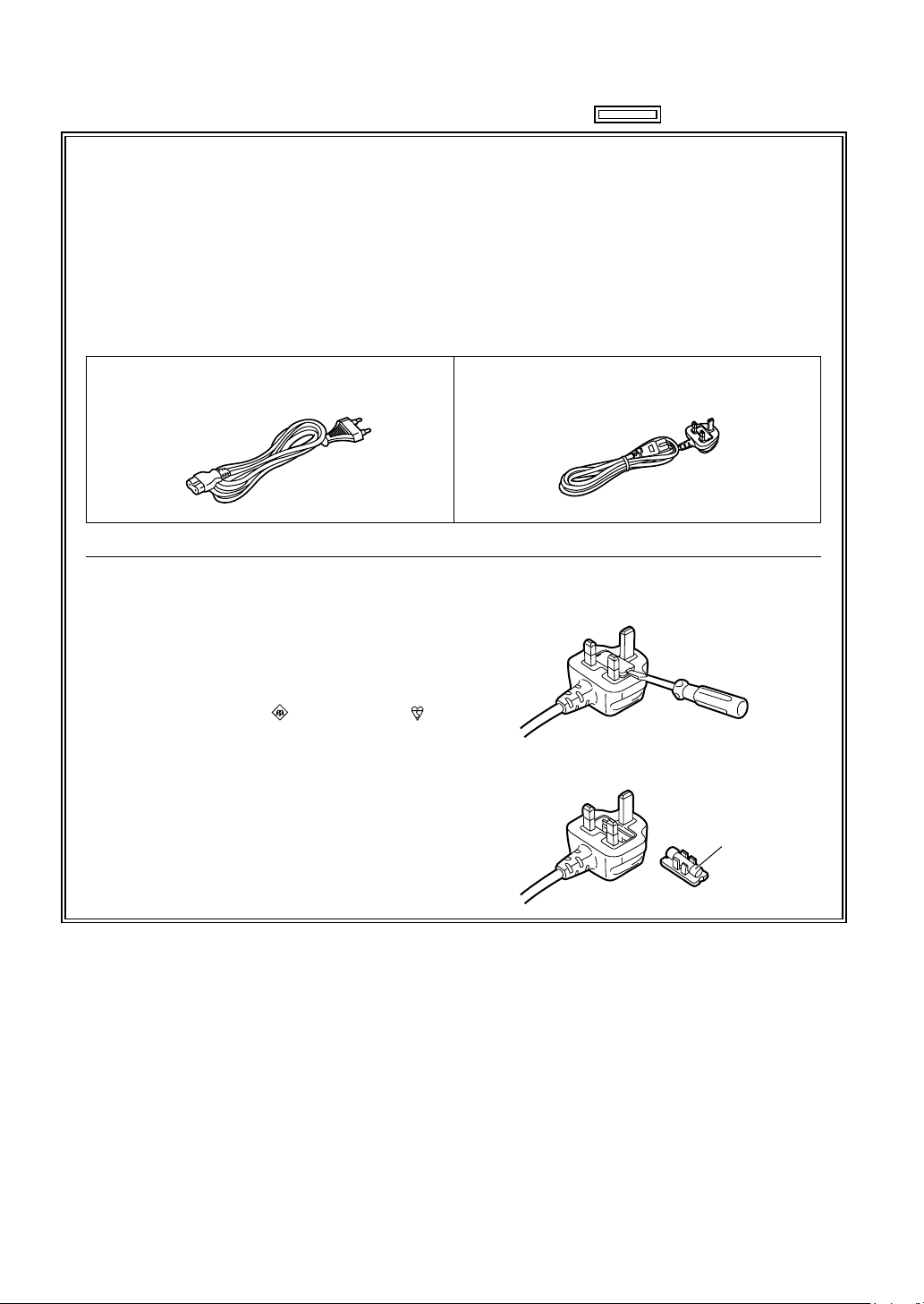
This product is equipped with 2 types of AC mains cable. One is for continental Europe, etc. and the
other one is only for U.K.
Appropriate mains cable must be used in each local area, since the other type of mains cable is
not suitable.
FOR CONTINENTAL EUROPE, ETC.
Not to be used in the U.K.
FOR U.K. ONLY
This appliance is supplied with a moulded three
pin mains plug for your safety and convenience.
A 5 amp fuse is fitted in this plug.
Should the fuse need to be replaced please
ensure that the replacement fuse has a rating of
5 amps and that it is approved by ASTA or BSI to
BS1362.
Check for the ASTA mark or the BSI mark
on the body of the fuse.
If the plug contains a removable fuse cover you
must ensure that it is refitted when the fuse is
replaced.
If you lose the fuse cover the plug must not be
used until a replacement cover is obtained.
A replacement fuse cover can be purchased from
your local Panasonic Dealer.
FOR U.K. ONLY
How to replace the fuse
1. Open the fuse compartment with a screwdriver.
2. Replace the fuse
Fuse
4
indicates safety information.
Caution for AC Mains Lead
For AC adaptor
FOR YOUR SAFETY PLEASE READ THE FOLLOWING TEXT CAREFULLY.
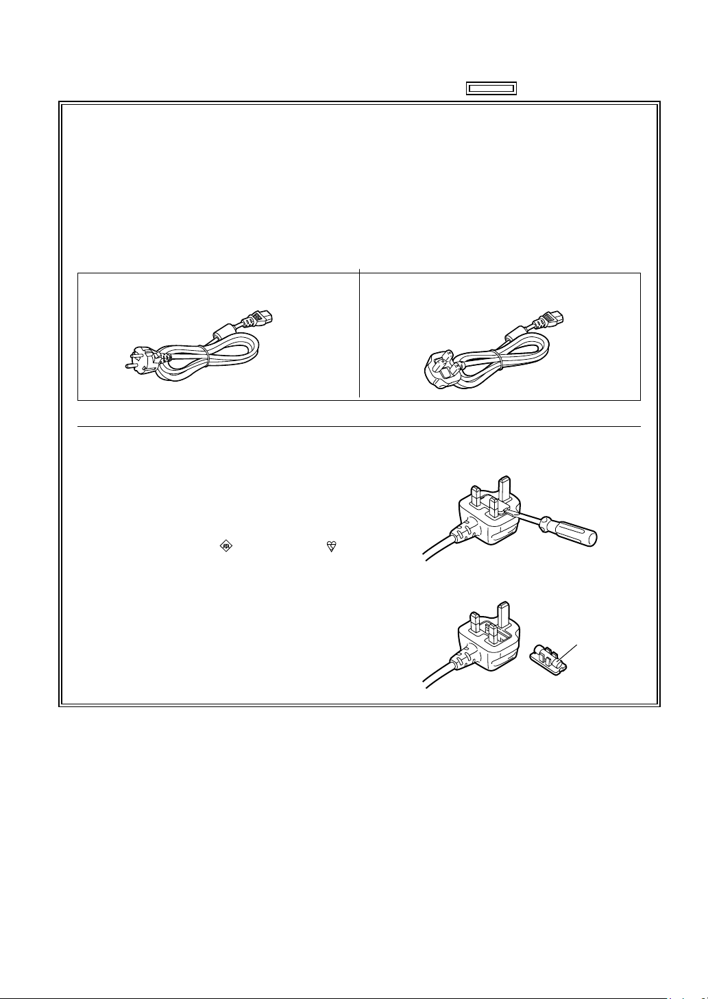
This product is equipped with 2 types of AC mains cable. One is for continental Europe, etc. and the
other one is only for U.K.
Appropriate mains cable must be used in each local area, since the other type of mains cable is
not suitable.
FOR CONTINENTAL EUROPE, ETC.
Not to be used in the U.K.
FOR U.K. ONLY
This appliance is supplied with a moulded three
pin mains plug for your safety and convenience.
A 5 amp fuse is fitted in this plug.
Should the fuse need to be replaced please
ensure that the replacement fuse has a rating of
5 amps and that it is approved by ASTA or BSI to
BS1362.
Check for the ASTA mark or the BSI mark
on the body of the fuse.
If the plug contains a removable fuse cover you
must ensure that it is refitted when the fuse is
replaced.
If you lose the fuse cover the plug must not be
used until a replacement cover is obtained.
A replacement fuse cover can be purchased from
your local Panasonic Dealer.
FOR U.K. ONLY
How to replace the fuse
1. Open the fuse compartment with a screwdriver.
2. Replace the fuse
Fuse
5
Recommendation for Use of Genuine Panasonic Battery
EU
ヴヵモ
ン
ヵ
ヶ
ョビ
ョピ
モ
ヵモ
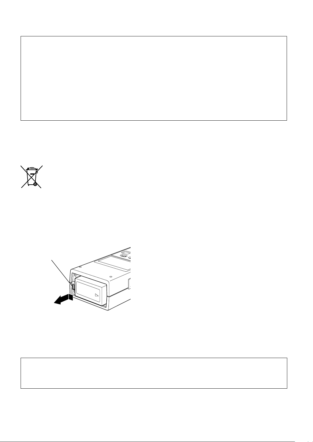
Battery release button
(Rechargeable Battery)
Thank you for using a Panasonic product.
It has been found that counterfeit batteries which look very similar to the genuine product are made
available to purchase in some markets. Some of these batteries are not adequately protected with internal
protection to meet the requirements of appropriate safety standards. There is a possibility that these
batteries may lead to fire or explosion. Please be advised that we are not liable for any accident or failure
occurring as a result of use of a counterfeit battery. To ensure that safe products are used we would
recommend that a genuine Panasonic battery is used.
Be aware that many batteries sold at extremely cheap prices or in situations where it is difficult to verify
•
the actual products before purchase have proven to be counterfeit.
Batteries that may be used with this product (Correct as of August 2010)
■
Panasonic CGA-D54 batteries may be used with this product.
The CGA-D54 batteries contain a function to enable verification as to whether they may be safely used with
this product.
To remove the battery
Main Power Battery
Press the battery release button.
Back-up Battery
For the removal of the battery for disposal at the
•
end of its service life, please consult your dealer.
Pursuant to at the directive 2004/108/EC, article 9(2)
Panasonic Testing Centre
Panasonic Service Europe, a division of Panasonic Marketing Europe GmbH
Winsbergring 15, 22525 Hamburg, F.R. Germany
6

Contents
Introduction
Preparation
Read this first! (AG-MSU10P and AG-MSU10E) ........................................2
Overview ..................................................................................................... 9
Standard accessories ................................................................................. 9
Optional units .............................................................................................. 9
Precautions ............................................................................................... 10
AG-MSU10 ........................................................................................ 10
AG-MBX10G interface box ............................................................... 11
AC adapter ....................................................................................... 11
Battery............................................................................................... 11
Control Reference Guide .......................................................................... 12
Front and Rear View.......................................................................... 12
Top ....................................................................................................13
Left and Right Sides ......................................................................... 14
Charging the battery ................................................................................. 15
Connecting and Disconnecting the Battery and the Power Cable ........... 16
Connecting the Battery ..................................................................... 16
Disconnecting the Battery ................................................................ 16
Connecting the Power Cable ............................................................ 16
Disconnecting the Power Cable ....................................................... 16
Turning the Unit on and off ....................................................................... 18
Turning the unit on ........................................................................... 18
Turning the unit off ........................................................................... 18
Auto Power Off During Operation ..................................................... 18
Calendar and Time Settings ..................................................................... 19
Inserting and Removing a P2 Card ..........................................................20
Inserting a P2 Card ........................................................................... 20
Removing a P2 Card ......................................................................... 20
Preventing Accidental Deletion ........................................................ 20
Installing and Removing Interface Boxes ................................................. 21
Installing an Interface Box in the Unit ............................................... 21
Removing the Interface Box From the Unit ....................................... 21
Formatting the Interface Box ....................................................................22
Operations
Connections
Setup
Copy Screen Control Reference Guide .................................................... 23
Selecting Storage Device ................................................................. 25
Copying All Clips on a P2 Card ................................................................ 26
Copying All Clips on a P2 Card ........................................................ 26
Selecting Clips for Copying ...................................................................... 28
Thumbnail Screen Operations .......................................................... 28
Copying Clips on a P2 Card ............................................................. 33
Copying Clips on a Storage Device ................................................ 34
Formatting P2 Cards ................................................................................ 36
Connecting to a PC................................................................................... 37
Using the Unit as a USB Device ....................................................... 37
Using the Unit as an eSATA Device .................................................. 37
Menu list ................................................................................................... 38
THUMBNAIL ..................................................................................... 39
7

OPERATION ...................................................................................... 39
STATUS ............................................................................................. 40
SETTING ........................................................................................... 40
Displaying Unit Information ...................................................................... 41
Log data ............................................................................................ 41
Operation time .................................................................................. 41
Software Version ............................................................................... 41
Interface Box
Interface Box Setup .................................................................................. 42
Installing an SSD (Solid State Drive) ................................................ 42
Attaching the Silicone Jacket ........................................................... 42
Control Reference Guide .......................................................................... 43
Connecting the Interface Box to a Personal Computer ............................ 44
For long and Trouble-free Operation
Internal Battery ......................................................................................... 45
Error Messages ......................................................................................... 45
Before Requesting a Repair .....................................................................49
Maintenance ............................................................................................. 49
Condensation............................................................................................ 49
Handling P2 Card Data ............................................................................. 50
Specifications .................................................................................................................................................... 51
Microsoft® and Windows® are registered trademarks or trademarks of Microsoft Corporation® of the United
•
States and/or other countries.
Macintosh® is a registered trademark of Apple Inc. in the United States.
•
Microsoft product screen shots reprinted with permission from Microsoft Corporation.
•
Names of products, brands, etc., appearing in this manual are trademarks or registered trademarks of their
•
respective owners.
Illustrations in this manual
Note that illustrations of the unit and menu screens may differ from the ones you actually see.
•
Page references
In this manual, references to pages are indicated as: ( page 00).
•
Terminology
A memory card with the “P2” logo (for example the separately sold AJ-P2C064AG) is referred to as a “P2
•
card.”
A hard disk drive is referred to as a “hard disk” or “HDD.”
•
A solid state drive is referred to as an “SSD.” An SSD is a semiconductor storage device built with flash
•
memory modules.
Externally connected hard disks, SSDs or interface boxes are referred to as ”Storage devices" or ”storage.”
•
A continuous video recording created using a P2 unit during a single recording is referred to as a ”clip.”
•
Panasonic Website
Information on topics, such as operation-confirmed SSDs and the latest drivers, can be found on the
•
Panasonic website. Access the following URL for the latest information not included in these Operating
Instructions.
http://pro-av.panasonic.net/
8

Introduction
Overview
The AG-MSU10 is a mobile storage unit designed for P2 cards (memory cards) and houses the AG-MBX10G
removable interface box for installing commercial SSDs and is also provided with USB 2.0 (Type A) and
eSATA connectors.
This unit copies data recorded using a P2 card camera-recorder or other device to a hard disk or other storage device connected to the removable interface box installed in this unit.
Standard accessories
AG-MBX10G removable interface box ........................................................................................................... 1
•
Operating instructions (this manual) ................................................................................................................ 1
•
CD-ROM (P2 driver, P2 card manager, install manual, operating instructions (this manual) .......................... 1
•
Battery (5400 mAh) (CGA-D54 for the AG-MSU10P / CGA-D54s for the AG-MSU10E) ................................. 1
•
Battery charger ................................................................................................................................................ 1
•
AC adapter ....................................................................................................................................................... 1
•
AC power supply cable (for the battery charger) ............................................................................................ 1
•
AC power supply cable (for the AC adapter) .................................................................................................. 1
•
USB cable ........................................................................................................................................................ 2
•
3.0 mm screws for SSD installation .................................................................................................................. 4
•
Silicone jacket for the AG-MBX10G ................................................................................................................. 1
•
Optional units
Introduction
AG-MBX10G removable interface box
•
Battery (5400 mAh) (CGA-D54 for the AG-MSU10P / CGA-D54s for the AG-MSU10E)
•
9

10
Precautions
AG-MSU10
Secure deletion of data from memory cards and storage devices prior to disposal or transfer of the
unit
The format and delete functions on this unit or a PC will only change the file management data and leave
data on the memory card or storage device intact. It is recommended that cards or storage devices either be
physically destroyed or that commercially sold software be used to completely delete any data they contain.
Management of data on memory cards and storage devices is the sole responsibility of the user.
Place of Installation
Do not install this unit in a location exposed to direct sunlight as this may deform the cabinet or damage the
LCD screen.
Liquid crystal displays
While 99.99 % or more of the pixels on an LCD screen will function normally, 0.01 % may either be dead or
•
constantly lit (seen as red, blue or green dots). This is not a malfunction.
There may be some unevenness on the screen depending on the image displayed.
•
Wiping or rubbing the LCD screen with a rough cloth may damage it.
•
Leaving an unchanging image on the screen for a long period of time may create a temporary afterimage
•
(burn-in).
LCD response and brightness vary with operating temperature.
•
In a high-temperature and high-humidity location, the LCD panel characteristics may change and result in
•
uneven image quality.
Information on software for this product
1. Included with this product is software licensed under the GNU General Public License (GPL) and GNU
Lesser General Public License (LGPL), and users are hereby informed that they have the right to obtain,
change and redistribute the source codes of this software.
Details on GPL and LGPL can be found on the installation CD provided with the unit. Refer to the folder
called “LDOC”.
(Details are given in the original (English-language) text.)
To obtain the source codes, go to the following home page:
https://eww.pavc.panasonic.co.jp/pro-av/
The manufacturer asks users to refrain from directing inquiries concerning the source codes they have
obtained and other details to its representatives.
2. Included with this product is software which is licensed under MIT-License.
This information is provided in the LDOC folder (in the original English language text) on the install CD-ROM
supplied with the unit.

AG-MBX10G interface box
Install a commercially available 2.5-type SSD with Serial ATA interface in the supplied AG-MBX10G removable interface box according to the instructions in “Interface Box Setup” (page 42).
Information on SSDs that we have tested is posted on our website.
•
Be sure to turn the unit off before inserting and removing the interface box in the unit.
•
Failure to heed this warning may result in damage to the unit.
Do not install a hard disk drive in the interface box.
•
AC adapter
Use the supplied AC adapter. Read the Operating Instructions before use.
“Connecting the Power Cable” (page 16 ).
Battery
Use the supplied battery. (CGA-D54 for the AG-MSU10P / CGA-D54s for the AG-MSU10E)
Battery characteristics
This unit uses a rechargeable lithiumion battery that uses its internal chemical reaction to generate electrical
energy. This reaction is easily influenced by the ambient temperature and humidity, and the battery's effective
operating time is reduced as the temperature rises or falls. In very low temperatures, the battery may last only
5 minutes.
Protective circuitry functions if you use the battery where it is very hot and you will have to wait before you
can use it again.
Introduction
Remove the battery after use.
Completely remove the battery. (The battery continues to be used even if you have turned the unit off.) The
battery can over discharge if you leave it in the unit and it may become impossible to recharge it.
11
12
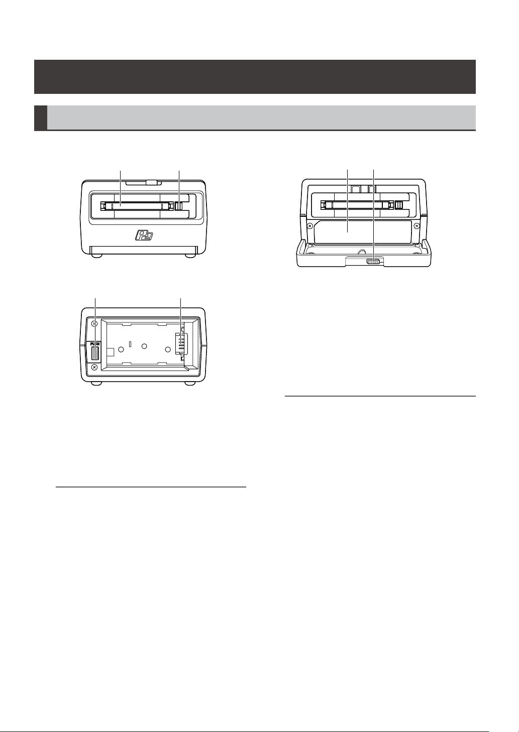
Front and Rear View
1 21 2
3 4
a
ヰヱユワ
3 4
a
ヰヱユワ
5 65 6
Front view
Rear view
Control Reference Guide
1.
P2 card slot
This slot is designed for P2 cards.
Before inserting a P2 card, make sure that the
EJECT button is in. Hold the card level as you
insert it.
For details, refer to “Inserting a P2 card”
(page 20).
NOTE:
• Never insert anything in the slot except P2 cards.
2.
EJECT button
Press to eject P2 cards from the slot.
For details, refer to “Removing a P2 card”
(page 20).
3.
Interface box slot
This slot is designed for an interface box (AGMBX10G). Hold the box level as you slide it
into the slot.
For details, refer to “Inserting and Removing
Interface Boxes” (page 21).
NOTE:
• Never insert anything in the slot except an interface
box.
• Turn off the unit before inserting and removing
interface box.
4.
Front door lock lever
Slide the lever to open the front door and insert
or remove an interface box.
For details, refer to “Inserting and Removing
Interface Boxes” (page 21).
5.
Battery lock release button
Use this button to remove a supplied battery or
AC adapter.
For details, refer to “Disconnecting the Bat-
tery” (page 16).
6.
Power inlet
Insert the supplied battery or AC adapter here.
For details, refer to “Connecting and Dis-
connecting the Battery and the Power
Cable” (page 16).
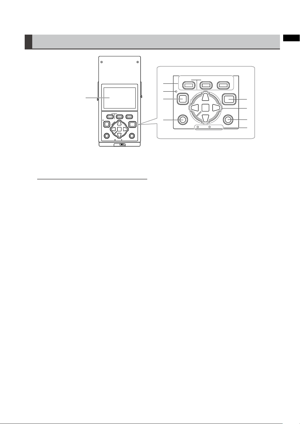
Top
ョヒ
ヱヰヸユン
ヴヵモンヵ
ヮユワヶ
ユヹリヵ
ヴユヵ
ヱビ
ヴヵヰンモヨユ
ョビ ョピ
ヶヴャ
ㄆヴモヵモ
ュユヷリヤユ
ョヒ
ヱヰヸユン
ヴヵモンヵ
ヮユワヶ
ユヹリヵ
ヴユヵ
ヱビ
ヴヵヰンモヨユ
ョビ ョピ
ヶヴャ
ㄆヴモヵモ
ュユヷリヤユ
7
8
9
10
12
13
14
15
11
ョヒ
ヱヰヸユン
ヴヵモンヵ
ヮユワヶ
ユヹリヵ
ヴユヵ
ヱビ
ヴヵヰンモヨユ
ョビ ョピ
ヶヴャ
ㄆヴモヵモ
ュユヷリヤユ
ョヒ
ヱヰヸユン
ヴヵモンヵ
ヮユワヶ
ユヹリヵ
ヴユヵ
ヱビ
ヴヵヰンモヨユ
ョビ ョピ
ヶヴャ
ㄆヴモヵモ
ュユヷリヤユ
7
8
9
10
12
13
14
15
11
Introduction
7.
82 mm (3.2 inch) LCD monitor
Displays thumbnails as well as P2 card and
interface box operating status.
11.
EXIT button
Press this button in a clip thumbnail, Properties, or in the Explore screen on the storage
device or other screen to return to the previous
NOTE:
• Use the steps below to adjusts the brightness of
the backlight. Select [SETTING] [LCD BACKLIGHT] from the menu.
For details, refer to “Menu list” (page 38).
• Use the steps below to have the LCD monitor
automatically turn off after a specified time (5 min)
of inactivity. Select [SETTING] [LCD TIMEOUT]
from the menu.
For details, refer to “Menu list” (page 38).
screen. You can also use [EXIT] in a menu and
press the SET button to the same effect.
12.
START button
Press to start copying a P2 card.
13.
Cursor (up/down/left/right) buttons/SET but-
ton
The four outer buttons are cursor buttons. Use
them to move the cursor in thumbnails, menus,
8.
Function buttons (F1/F2/F3)
Press to use the functions displayed at the bottom of the screen.
Explorer, etc.
The SET button at the center is used to select
menu items and clips.
For details, refer to “Cursor operations”
(page 30).
9.
POWER LED
Lights when the unit is ON.
The POWER LED flashes during shutdown.
14.
MENU button
Press to open the menu. Press again to return
to the previous screen.
10.
POWER button
For details, refer to “Menu list” (page 38).
Use to turn the power ON and OFF.
15.
When the unit is OFF, hold down the POWER
button for 1 second to turn it ON.
When the unit is ON, hold down the POWER
button for 2 seconds to turn it OFF.
For details, refer to “Turning the unit on and
off” (page 18).
Access LEDs
P2:
The LED is on when a P2 card is inserted and
flashes when it is accessed.
STORAGE:
The LED is on when the drive in the interface
box or an external storage unit is connected
for copying and flashes when any of the drives
are accessed.
For details, refer to “Connections” (page 37).
13
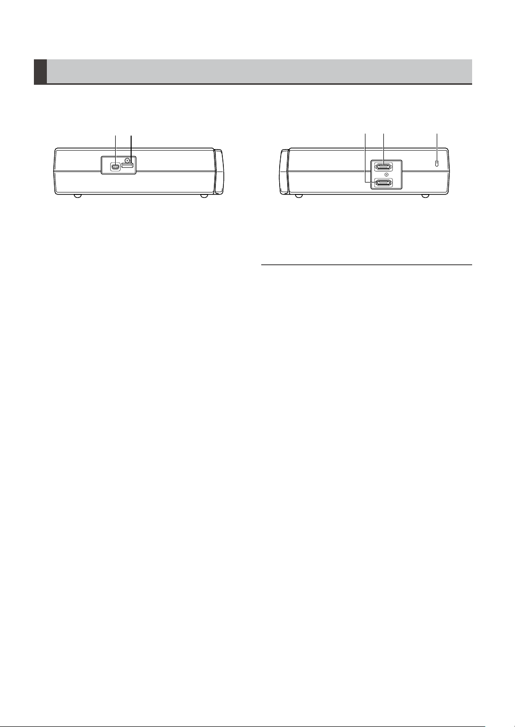
Left and Right Sides
HOST
DEVICE
16 17
HOST
DEVICE
16 17
HOST
DEVICE
1918 20
HOST
DEVICE
1918 20
16.
USB 2.0 DEVICE connector (Type Mini-B)
Connect personal computers and other devices for use in the USB device mode.
For details, refer to “Using the Unit as a USB
Device” (page 37).
17.
USB 2.0 HOST connector (Type A)
Enables connection of a variety of storage
devices using the unit as a USB host.
For example, hard disks that support USB 2.0.
For details, refer to “Selecting Storage De-
vice” (page 25).
18.
eSATA DEVICE connector
The eSATA connector on the interface box
allows you to connect a personal computer or
other device.
For details, refer to “Using the unit as an
eSATA device” (page 37).
19.
eSATA HOST connector
Enables connection of a hard disk drive or
solid state drive with an eSATA connector using the unit as host device.
For details, refer to “Selecting Storage De-
vice” (page 25).
20.
Security lock slot
Used for attaching security cables. For details
on connection, refer to the instruction manual
supplied with the cable. Security locks and
security cables help prevent theft. However, in
the event that theft does occur, Panasonic is
not liable for any resulting damages.
14
NOTE:
• It may not be possible to connect an eSATA storage
device that does not support the LINUX operating system.
• Some eSATA storage devices may prolong the startup
time of the unit.
• This unit supports USB bus power (5 V, 0.5 A) but some
storage devices may have difficulties starting up using
USB bus power. Should this happen, provide the storage
device with a separate power supply.
• This unit does not support storage devices that are 2 TB
(2,048 GB) or larger.
• Some storage devices and cables may not operate normally.
• Use a storage device with sufficient space for copying.
• Do not connect a storage device to hubs or other connections that involve multiple units even when it is not powered.
• During formatting and copying, do not disconnect cables,
do not remove a P2 card and do not power off this unit
and the storage device. Otherwise this unit and the storage device must be rebooted. The P2 card may have
become damaged.
• A storage device is a high-precision instrument whose
read and write functions may fail if used in an unsuitable
environment. Please note that Panasonic accepts no
liability whatsoever for data loss or other losses either
direct or indirect arising from storage device damage or
other defects.
• When data from this unit is copied to a storage device
and is edited on another computer, the data may no longer work in this unit and storage device data may become
corrupted.
• Repair bad clips on P2 cards before copying them to a
storage device.
• SATA (serial ATA) or PATA (parallel ATA) interface storage
devices connected using a USB converter cable may not be
recognized.
POWER
CHARGE
POWER
CHARGE
Preparation
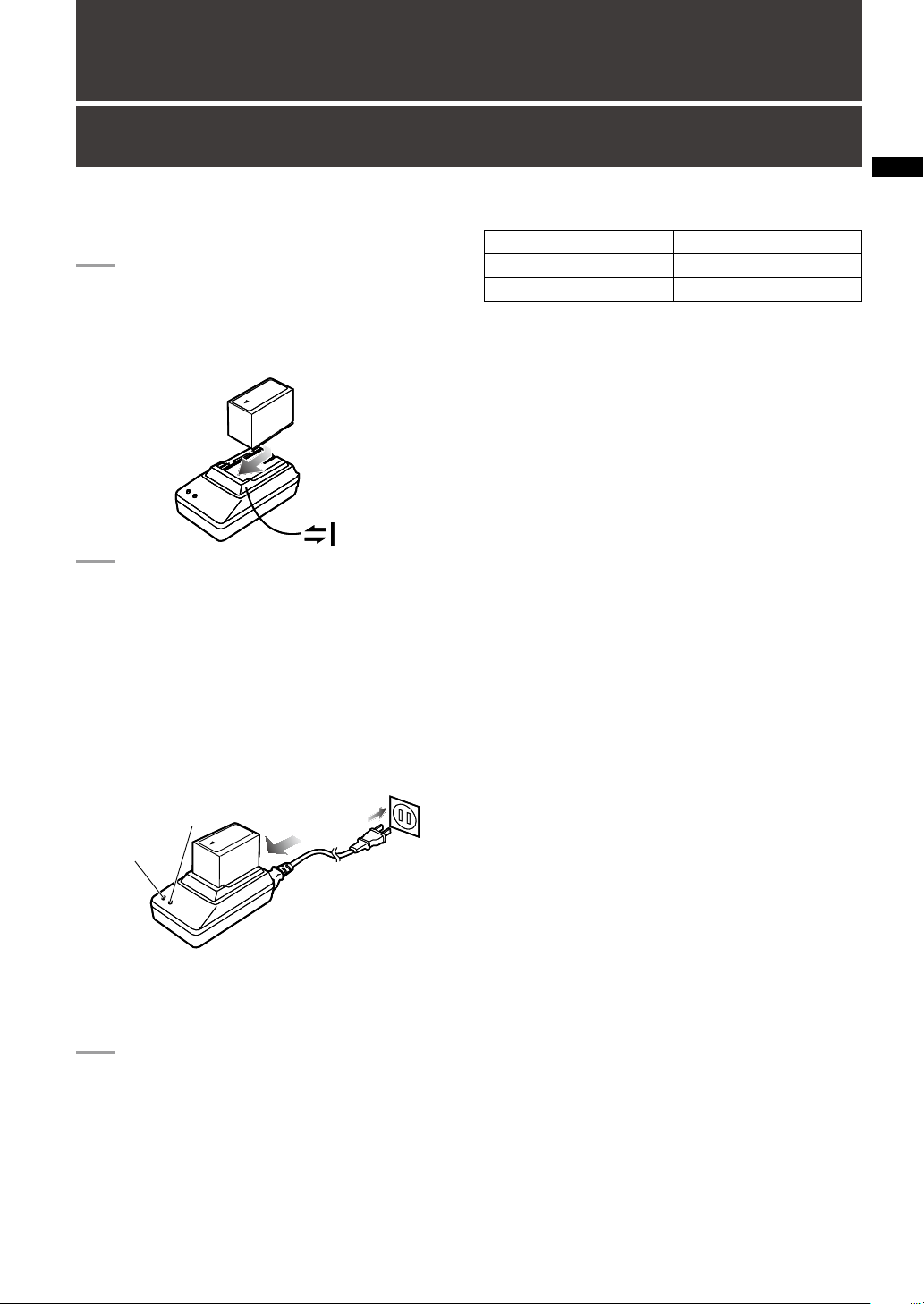
Charging the battery
The battery is not charged when the product is
purchased. Use the steps below to fully charge the
battery using the supplied charger.
Place the battery level on the charger
1
and slide it in the direction of the arrows
on the charger.
Connect the AC power supply cable to
2
the charger and connect the power plug
to a wall outlet.
• The POWER lamp and CHARGE lamp on
the charger lights indicating that charging
has started.
• If the CHARGE lamp does not light when
the battery is installed, reinstall the battery
correctly.
Charging time and battery life estimates for the
supplied battery
Capacity 5400 mAh
Charging time Approx. 330 min.
Continuous copying time Approx. 400 min.
• The table above shows expected battery performance with an E-series P2 card in the AGMBX10G removable interface box.
• This level of performance is achieved at an ambient operating temperature of 20 °C (68 °F) and
an ambient operating humidity of 60 %. Higher
temperature and humidity levels will extend the
charging time.
• The battery becomes hot during charging.
• When the battery temperature becomes excessively high or low, or it has become discharged
after a long period of inactivity, the CHARGE lamp
may flash a two or three times before automatic
charging starts.
• If the CHARGE lamp continues flashing when the
battery is at normal temperature, it may be defective and you should contact your supplier.
• Charging time becomes longer for a hot battery.
• Using the charger or AC adapter near a radio may
interfere with radio reception. Place the charger or
AC adapter at least 1 meter away from a radio.
• The charger may emit noise during charging. This
is not a malfunction.
• No guarantees are given for the operation of the
CGR-D16/CGR-D16s (1600 mAh) battery pack.
Preparation
• The CHARGE lamp on the charger goes
out when charging ends.
Slide the battery off the charger.
3
15
16
Connecting and Disconnecting the Battery and the Power Cable
ヴ
ヵ
モ
ン
ヵ
ョピ
ヴ
ヵ
モ
ン
ヵ
ョピ
ヴヵモ
ン
ヵ
ヶ
ョビ
ョピ
モ
ヵモ
Battery lock release button
ヴヵモ
ン
ヵ
ヶ
ョビ
ョピ
モ
ヵモ
Battery lock release button
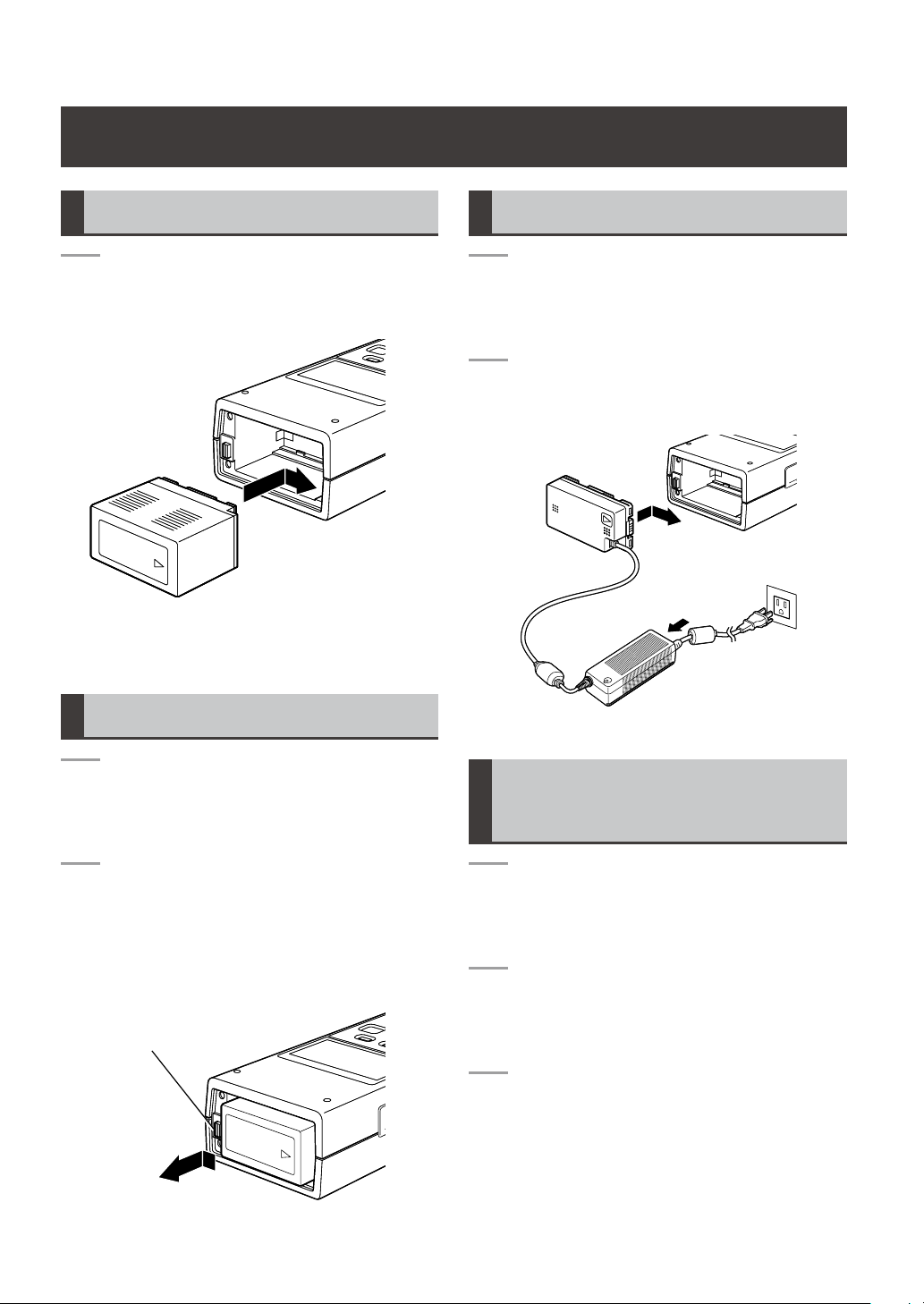
Connecting the Battery
Slide in the battery until it clicks into
1
place.
Disconnecting the Battery
Connecting the Power Cable
Connect the AC power supply cable to
1
the AC adapter, and then connect the
power plug to a wall outlet.
Slide in the DC power supply cable plate
2
until it clicks into place.
Hold down the POWER button for 2
1
second or longer to turn the unit off and
make sure that the POWER LED is off.
Depress the battery lock release button
2
to slide out the battery.
• Hold the battery to prevent it from falling
out.
Disconnecting the Power Cable
Hold down the POWER button for 2
1
second or longer to turn the unit off and
make sure that the POWER LED is off.
Depress the battery lock release button
2
and slide out the DC power supply cable
plate.
Disconnect the AC power supply cable
3
from the wall outlet.
 Loading...