

Page 1

Operating Instructions
EJ
Memory Card Portable Recorder
Model No.
AG-MDR25P
AG-MDR25E
Please read these instructions carefully before using this product, and save this manual for future use.
PJ
F0517SQ0
ENGLISH
DVQP1328ZA
Page 2

ɛɴɥɝɚɪɫɤɢ
ɉɨɫɟɬɟɬɟɫɥɟɞɧɢɹɭɟɛɫɚɣɬ ɨɬɧɨɫɧɨɢɧɮɨɪɦɚɰɢɹɡɚɛɟɡɨɩɚɫɧɨɫɬɬɚɢ ɜ
ɚɠɧɢ
ɭɜɟɞɨɦɥɟɧɢɹɡɚɩɪɨɞɭɤɬɚ
Hrvatski
=DVLJXUQRVQHLQIRUPDFLMHLYDåQH REDYLMHVWL R SURL]YRGX SRVMHWLWH
VOMHGHüX
LQWHUQHWVNXVWUDQLFX
ýHãWLQD
1DQiVOHGXMtFtPZHEXQDMGHWHEH]SHþQRVWQtLQIRUPDFHDGĤOHåLWpSR]QiPN\
N
WRPXWRSURGXNWX
'DQVN
%HV¡JI¡OJHQGHZHEVLGHIRUVLNNHUKHGVLQIRUPDWLRQ RJ YLJWLJH EHPUNQLQJHU
YHGU¡UHQGHSURGXNWHW
1HGHUODQGV
*DQDDUGHYROJHQGHZHEVLWH YRRU YHLOLJKHLGVLQIRUPDWLH HQ EHODQJULMNH
PHOGLQJHQ
RYHUKHWSURGXFW
(HVWL
7RRGHWSXXGXWDYD RKXWXVWHDEH MD ROXOLVWH PlUNXVWH VDDPLVHNV NODVWDJH
MlUJPLVW
YHHELOHKWH
Suomi
.l\VHXUDDYDOODYHUNNRVLYXOODVDDGDNVHVLWXUYDOOLVXXVWLHWRMDMD
WlUNHLWlWLHWRMDOLLWW\HQ
ODLWWHHVHHQ
ǼȜȜȘȞȚțȐ
īȚĮʌȜȘȡȠijȠȡȓİȢ ıȤİIJȚțȐȝİșȑȝĮIJĮĮıijȐȜİȚĮȢțĮȚıȘȝĮȞIJȚțȑȢİȚįȠʌ
ȠȚȒıİȚȢʌȠȣ
ĮijȠȡȠȪȞIJȠʌȡȠȧȩȞıĮȢİʌȚıțİijIJİȓIJİIJȠȞȚıIJȩIJȠʌȠʌȠȣĮțȠȜȠȣșİȓ
Magyar
$WHUPpNNHONDSFVRODWRVEL]WRQViJLLQIRUPiFLyNpUWpVIRQWRVpUWHVtWpVHNpUWOiWRJDVVRQ
HOD]DOiEELZHEROGDOUD
/DWYLHãX
/DLLHJnjWXLQIRUPƗFLMXSDUGURãƯEXXQVNDWƯWXVYDUƯJXVSD]LƼRMXPXV
SDUãRSURGXNWX
DSPHNOƝMLHWWƗOƗNQRUƗGƯWRWƯPHNƺDYLHWQL
/LHWXYLǐ
-HLUHLNLD VDXJRVLQIRUPDFLMRVLUVYDUELǐ SUDQHãLPǐ DSLHJDPLQƳ
DSVLODQN\NLWHWROLDX
QXURG\WRMHVYHWDLQơMH
3ROVNL
,QIRUPDFMHREH]SLHF]HĔVWZLHLZDĪQHLQIRUPDFMHRSURGXNFLH]QDMGXMą
VLĊZ
SRQLĪV]HMZLWU\QLHLQWHUQHWRZHM
Português
&RQVXOWHRVHJXLQWHZHEVLWHSDUD DV LQIRUPDo}HV GH VHJXUDQoD H LPSRUWDQWHV
QRWL¿FDo}HVVREUHRSURGXWR
5RPkQă
9L]LWD܊LXUPăWRDUHDSDJLQăZHESHQWUXLQIRUPDĠLLGHVHFXULWDWH܈L
QRWL¿FăULLPSRUWDQWH
FXSULYLUHODSURGXV
6ORYHQVN\
3UHEH]SHþQRVWQpLQIRUPiFLHDG{OHåLWpR]QiPHQLDV~YLVLDFHVSURGXNWRP
QDYãWtYWH
W~WRZHERY~VWUiQNX
6ORYHQãþLQD
=DYDUQRVWQHLQIRUPDFLMHLQSRPHPEQD REYHVWLOD Y ]YH]L ] L]GHONRP
RELãþLWH
QDVOHGQMHVSOHWQRPHVWR
6YHQVND
%HV|NI|OMDQGHZHEESODWVI|U VlNHUKHWVLQIRUPDWLRQ RFK YLNWLJD PHGGHODQGHQ
RP
SURGXNWHQ
http://pro-av.panasonic.net/en/manual/index.html
- 2 -
Page 3
Information for Your Safety
WARNING:
To reduce the risk of fire, electric shock or product damage,
≥ Do not expose this unit to rain, moisture, dripping or splashing.
≥ Do not place objects filled with liquids, such as vases, on this unit.
≥ Use only the recommended accessories.
≥ Do not remove covers.
≥ Do not repair this unit by yourself. Refer servicing to qualified service personnel.
CAUTION!
To reduce the risk of fire, electric shock or product damage,
≥ Do not install or place this unit in a bookcase, built-in cabinet or in another confined space. Ensure this unit is
well ventilated.
≥ Do not obstruct this unit’s ventilation openings with newspapers, tablecloths, curtains, and similar items.
≥ Do not place sources of naked flames, such as lighted candles, on this unit.
CAUTION:
About using a headphone
≥ Excessive sound pressure from earphones and headphones can cause hearing loss.
≥ Listening at full volume for long periods may damage the user’s ears.
CAUTION:
Do not leave the unit in direct contact with the skin when in use.
≥ Low temperature burns may result if the skin is left in direct contact with the high temperature parts of the unit
or heated air from the ventilation openings of the unit.
CAUTION:
About using SD Card
≥ Keep the Memory Card out of reach of children to prevent swallowing.
indicates safety information.
∫ Product identification marking
Product Location
Memory Card Portable Recorder Bottom
AC adaptor Bottom
This unit is intended for use in moderate and tropical climates. (Southeast Asia, Middle East only)
This unit is intended for use in moderate climates. (Except Southeast Asia, Middle East)
- 3 -
Page 4
<For the U.S.A. and Canada only>
AC adaptor
This AC adaptor operates on AC between 100 V and 240 V.
But
≥ In the U.S.A. and Canada, the AC adaptor must be connected to a 120 V AC power supply only.
≥ When connecting to an AC supply outside of the U.S.A. or Canada, use a plug adaptor to suit the AC outlet
configuration.
≥ When connecting to a supply of greater than AC 125 V, ensure the cord you use is suited to the voltage of the AC
supply and the rated current of the AC adaptor.
≥ Contact an electrical parts distributor for assistance in selecting a suitable AC plug adaptor or AC cord set.
The power plug is the disconnecting device. Install this unit so that the power plug can be unplugged from the socket
outlet immediately.
≥ The unit is in the standby condition when the AC adaptor is connected. The primary circuit is always “live” as long
as the AC adaptor is connected to an electrical outlet.
≥ Do not use any other AC adaptors except the supplied one.
<For other countries or regions>
The mains plug is the disconnecting device. Install this unit so that the mains plug can be unplugged from the socket
outlet immediately.
<For the U.S.A. and Canada only>
Conforms to UL STD 60065.
Certified to CAN/CSA STD C22.2 No.60065.
<For Europe only>
∫ EMC Electric and magnetic compatibility
This symbol (CE) is located on the rating plate.
∫ Concerning the battery
CAUTION
≥ Danger of explosion if battery is incorrectly replaced. Replace only with the type recommended by the
manufacturer.
≥ When disposing of the batteries, please contact your local authorities or dealer and ask for the correct method of
disposal.
Warning
Risk of fire, explosion and burns. Do not disassemble, heat above 60 oC (140 oF) or incinerate.
≥ We recommend using Panasonic batteries (VW-VBD58/AG-VBR59/AG-VBR89/AG-VBR118).
≥ If you use other batteries, we cannot guarantee the quality of this product.
≥ Do not heat or expose to flame.
≥ Do not leave the battery(ies) in a car exposed to direct sunlight for a long period of time with doors and windows
closed.
- 4 -
Page 5

Battery pack (Lithium ion battery pack)
≥ Use the specified unit to recharge the battery pack.
≥ Do not use the battery pack with equipment other than the specified unit.
≥ Do not get dirt, sand, liquids, or other foreign matter on the terminals.
≥ Do not touch the plug terminals (i and j) with metal objects.
≥ Do not disassemble, remodel, heat or throw into fire.
If any electrolyte should come into contact with your hands or clothes, wash it off thoroughly with water.
If any electrolyte should come into contact with your eyes, never rub the eyes. Rinse eyes thoroughly with water, and
then consult a doctor.
∫ IMPORTANT SAFETY INSTRUCTIONS
Read these operating instructions carefully before using the unit. Follow the safety instructions on the unit and the
applicable safety instructions listed below. Keep these operating instructions handy for future reference.
1) Read these instructions.
2) Keep these instructions.
3) Heed all warnings.
4) Follow all instructions.
5) Do not use this apparatus near water.
6) Clean only with dry cloth.
7) Do not block any ventilation openings. Install in accordance with the manufacturer ’s instructions.
8) Do not install near any heat sources such as radiators, heat registers, stoves, or other apparatus (including
amplifiers) that produce heat.
9) Do not defeat the safety purpose of the polarized or grounding-type plug. A polarized plug has two blades with
one wider than the other. A grounding-type plug has two blades and a third grounding prong. The wide blade or
the third prong are provided for your safety. If the provided plug does not fit into your outlet, consult an electrician
for replacement of the obsolete outlet.
10) Protect the power cord from being walked on or pinched particularly at plugs, convenience receptacles, and the
point where they exit from the apparatus.
11) Only use attachments/accessories specified by the manufacturer.
12) Use only with the cart, stand, tripod, bracket, or table specified by the manufacturer, or sold
with the apparatus. When a cart is used, use caution when moving the cart/apparatus
combination to avoid injury from tip-over.
13) Unplug this apparatus during lightning storms or when unused for long periods of time.
14) Refer all servicing to qualified service personnel. Servicing is required when the apparatus
has been damaged in any way, such as power-supply cord or plug is damaged, liquid has
been spilled or objects have fallen into the apparatus, the apparatus has been exposed to rain or moisture, does
not operate normally, or has been dropped.
- 5 -
Page 6
FCC NOTICE (USA)
Declaration of Conformity
Model Number: AG-MDR25P
Trade Name: Panasonic
Responsible Party: Panasonic Corporation of North America
Support contact: 1-800-524-1448
This device complies with Part 15 of the FCC Rules.
Operation is subject to the following two conditions:
(1) This device may not cause harmful interference, and (2) this device must accept any interference received,
including interference that may cause undesired operation.
To assure continued compliance, follow the attached installation instructions and do not make any unauthorized
modifications.
CAUTION:
This equipment has been tested and found to comply with the limits for a Class B digital device, pursuant to Part
15 of the FCC Rules. These limits are designed to provide reasonable protection against harmful interference in
a residential installation. This equipment generates, uses and can radiate radio frequency energy and, if not
installed and used in accordance with the instructions, may cause harmful interference to radio
communications. However, there is no guarantee that interference will not occur in a particular installation. If this
equipment does cause harmful interference to radio or television reception, which can be determined by turning
the equipment off and on, the user is encouraged to try to correct the interference by one or more of the
following measures:
≥ Reorient or relocate the receiving antenna.
≥ Increase the separation between the equipment and receiver.
≥ Connect the equipment into an outlet on a circuit different from that to which the receiver is connected.
≥ Consult the dealer or an experienced radio/TV technician for help.
The user may find the booklet “Something About Interference”
available from FCC local regional offices helpful.
FCC Warning:
To assure continued FCC emission limit compliance, follow the attached installation instructions and the user
must use only shielded interface cables when connecting to host computer or peripheral devices. Also, any
unauthorized changes or modifications to this equipment could void the user’s authority to operate this device.
NOTIFICATION (Canada)
CAN ICES-3(B)/NMB-3(B)
Two Riverfront Plaza Newark NJ07102
indicates safety information.
<For U.S.A. only>
AG-MDR25P
- 6 -
Page 7

NOTICE FOR MEDICAL USE
≥ This is an apparatus intended for recording playing-back of image from specified camera classified as;
• Protection against Electric Shock Class II
• Protection against Ingress of Water IPX0
• Mode of Operation Continuous
• Not suitable for use in the presence of a Flammable Anaesthetic mixture with Air or with Oxygen or Nitrous
Oxide.
≥ Equipment connected to signal input and/or output parts must be certified according to the appropriate IEC
60601-1 and/or IEC 60601-1 harmonized national standard. Furthermore all configurations shall comply with
standard IEC 60601-1 ME system. Everybody who connects additional equipment to the signal input part, or
signal output part configures a medical system, and is therefore responsible that the system complies with the
requirements of the standard IEC 60601-1. If in doubt, consult the technical service department or your local
representative.
Leakage current of this unit may be exceeded the allowable value when conductively connected to other
equipment. To avoid increment of the leakage current, separation device shall be applied.
≥ Use with the Compact Camera Head (AG-MDC20G: Optional).
≥ Do not use the Compact Camera Head in handheld style.
≥ Operator: To reduce the risk of electric shock, do not touch the patients during operating the equipment.
∫ TRANSPORT AND STORAGE CONDITION
AMBIENT TEMPERATURE
-10°C to 60°C
RELATIVE HUMIDITY
30% to 80%
ATMOSPHERIC PRESSURE
500 hPa to 1060 hPa
indicates safety information.
Operating precaution
Operating near any appliance which
generates strong magnetic fields may
give rise to noise in the video and audio
signals.
If this should be the case, deal with the
situation by, for instance, moving the
source of the magnetic fields away from
the unit before operation.
- 7 -
Page 8
For the AC mains plug of three pins
∫ Caution for AC mains lead
For your safety, please read the following text carefully.
This appliance is supplied with a moulded three pin
mains plug for your safety and convenience. A 5-ampere
fuse is fitted in this plug.
Should the fuse need to be replaced please ensure that
the replacement fuse has a rating of 5-ampere and that it
is approved by ASTA or BSI to BS1362.
Check for the ASTA mark Ï or the BSI mark Ì on the
body of the fuse.
If the plug contains a removable fuse cover you must
ensure that it is refitted when the fuse is replaced.
If you lose the fuse cover the plug must not be used until
a replacement cover is obtained.
A replacement fuse cover can be purchased from your
local dealer.
Before use
Remove the connector cover.
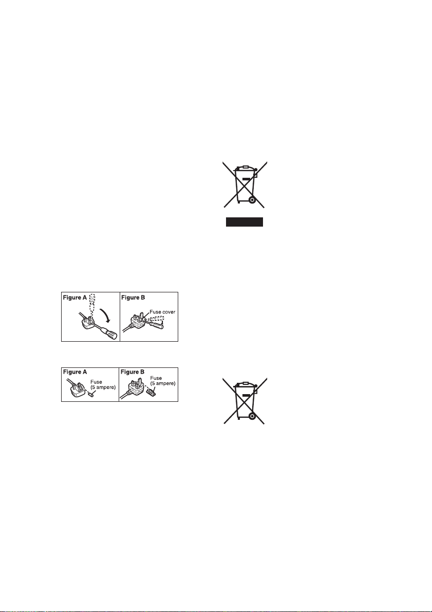
How to replace the fuse
The location of the fuse differ according to the type of AC
mains plug (figures A and B).
Confirm the AC mains plug fitted and follow the
instructions below.
Illustrations may differ from actual AC mains plug.
1. Open the fuse cover with a screwdriver.
2. Replace the fuse and close or attach the fuse
cover.
<For USA only>
Disposal may be regulated in your community due to
environmental considerations. For disposal or recycling
information, please visit Panasonic website: http://
www.panasonic.com/environmental or call 1-888-769-
0149.
<For Europe only>
∫ Disposal of Old Equipment and
Batteries
Only for European Union and
countries with recycling systems
These symbols on the products,
packaging, and/or accompanying
documents mean that used
electrical and electronic products
and batteries must not be mixed
with general household waste.
For proper treatment, recovery
and recycling of old products and
used batteries, please take them
to applicable collection points in accordance with
your national legislation.
By disposing of them correctly, you will help to
save valuable resources and prevent any
potential negative effects on human health and
the environment.
For more information about collection and
recycling, please contact your local municipality,
dealer or supplier.
Penalties may be applicable for incorrect disposal
of this waste, in accordance with national
legislation.
- 8 -
Note for the battery symbol
(bottom symbol):
This symbol might be used in
combination with a chemical
symbol. In this case it complies
with the requirement set by the
Directive for the chemical involved.
Page 9
<For India only>
AC adaptor information
AEEE Yönetmeliğine Uygundur.
AEEE Complies with Directive of Turkey.
IS 616/IEC 60065
R-41016268
To remove the battery
Main Power Battery (Lithium ion Battery)
While pressing the battery release button, remove the
battery.
Back-up Battery (Lithium Battery)
≥ For the removal of the battery for disposal at the end
of its service life, please consult your dealer.
Note regarding the Power Management
function specified under COMMISSION
REGULATION (EC) No 1275/2008
implementing Directive 2009/125/EC of the
European Parliament and of the Council.
This device is designed and manufactured for use at a
broadcasting station and/or in a similar environment.
This device is not equipped with a Power Management
function or the Power Management function is set to OFF
as it will prevent the device from fulfilling its intended
purpose for the reasons below.
1. If the device is a Studio Camera, a Weather Camera,
a Mixer or other processor:
A Power Management function may cause the device
to suddenly stop during recording or while On Air.
2. If the device is a Studio Monitor:
A Power Management function may cause video for
the confirmation of whether a signal is normal, or
whether the signal has been lost, to be un-viewable.
3. If the device is a Camera Recorder:
A professional camera recorder must be able to start
quickly at any time, but a Power Management function
will cause an increase in the time taken to resume
from Stand-by mode.
- 9 -
Page 10

∫ Cautions for use
About this unit
The unit and the SD card become warm during
use. This is not a malfunction.
Keep this unit as far away as possible from
electromagnetic equipment (such as microwave
ovens, TVs, video games etc.).
≥ If you use this unit on top of or near a TV, the pictures
and/or sound on this unit may be disrupted by
electromagnetic wave radiation.
≥ Do not use this unit near cell phones because doing so
may result in noise adversely affecting the pictures
and/or sound.
≥ Recorded data may be damaged, or pictures may be
distorted, by strong magnetic fields created by
speakers or large motors.
≥ Electromagnetic wave radiation generated by
microprocessors may adversely affect this unit,
disturbing the pictures and/or sound.
≥ If this unit is adversely affected by electromagnetic
equipment and stops functioning properly, turn this unit
off and remove the battery or disconnect AC adaptor.
Then reinsert the battery or reconnect AC adaptor and
turn this unit on.
Do not use this unit near radio transmitters or highvoltage lines.
≥ If you record near radio transmitters or high-voltage
lines, the recorded pictures and/or sound may be
adversely affected.
About connecting to a PC
≥ Please use a commercially available cable compatible
with the USB 2.0 standard. Connect a miniB terminal
to this unit.
When connecting to the dedicated Camera Head
(AG-MDC20G)
≥ Always use a genuine Panasonic Camera head option
cable (AG-C20003G (3 m (118-1/8 q)), AG-C20020G
(20 m (787-3/8 q)): optional).
When connecting to a network
≥ LAN cable
(328 feet)
* Use of an STP (shielded twisted pair) cable is
recommended.
When connecting to an SDI input/output device
≥ To connect to the SDI IN terminal or SDI OUT terminal,
use a double-shielded BNC cable equivalent to 5C-FB
(commercially-available).
Note on viewing motion pictures/still pictures on an
external monitor
≥ Use a commercially-available High Speed HDMI cable.
If possible, we recommend using a cable with a length
of 3 m (9.84 feet) or less.
*
(category 5 or above), max. 100 meters
Make sure to use the supplied cords. If you use
optional accessories, use the cords and the cables
supplied with them.
Do not extend the cords and the cables.
Do not spray insecticides or volatile chemicals onto
the unit.
≥ If the unit is sprayed with such chemicals, its body may
be marred and the surface finish may peel off.
≥ Do not leave rubber or plastic products in contact with
the unit for a long time.
When you use the unit in a sandy or dusty place
such as a beach, do not let sand or fine dust get into
the body and terminals of the unit.
Also, keep the unit away from sea water.
≥ Sand or dust may damage the unit. (Care should be
taken when inserting and removing a card.)
≥ If sea water splashes onto the unit, wipe off the water
with a well wrung cloth. Then wipe the unit again with a
dry cloth.
When carrying the unit, do not drop or bump it.
≥ A strong impact can break the unit’s casing, causing it
to malfunction.
Maintenance Inspections
≥ For your safety, it is recommended that maintenance
inspections are carried out on an annual basis.
Cleaning
When cleaning, do not use benzine or thinner.
Using benzine or paint thinners may deform the recorder
and/or cause the surface finish to peel off.
Cleaning procedure
1. When cleaning, unplug the power cord and remove
the battery.
2. Use a soft, clean cloth to wipe the recorder. To remove
stubborn dirt, wipe the recorder with a cloth moistened
with neutral detergent that has been diluted with water
and then use a dry cloth to take up the remaining
moisture.
3. Use a cloth moistened in ethanol for disinfection and
thoroughly wrung out to remove dust and dirt from the
recorder.
4. Be sure to thoroughly dry the recorder after cleaning it
with ethanol for disinfection.
When you are not going to use the unit for an
extended time
≥ When storing the unit, it is recommended that you
place a desiccant (silica gel) in with it.
About terminal protection
≥ When not using the connecting terminal, please attach
the cover.
Do not allow the cord to drag on the ground or pull a
connected cord along the passage
≥ The cord will be damaged, causing fire or electrical
shock, when the cord gets caught by the feet, excite
will also cause personal injury.
Please use this unit at least 30 cm (0.98 feet) from
surrounding walls.
- 10 -
Page 11

Information about compliance with IEC 60601
standards
≥ Evaluated against the technical requirements of IEC
60601-1/IEC 60601-1-2.
(Excluding RA process evaluation)
≥ This unit is not Medical Electrical Equipment.
About the battery (optional)
The battery used in this unit is a rechargeable lithium-ion
battery. It is susceptible to humidity and temperature and
the effect increases the more the temperature rises or
falls. In cold areas, the full charge indication may not
appear or the low battery indication may appear about
5 minutes after starting use. At high temperatures, the
protection function may be triggered, making it
impossible to use the unit.
Be sure to detach the battery after use.
≥ If the battery is left attached, a minute amount of
current continues to flow even if the unit is off. Keeping
the unit in this state may result in over discharge of the
battery. This may result in you not being able to use
the battery even after it is charged.
≥ The battery should be stored in the vinyl bag so metal
does not come into contact with the terminals.
≥ The battery should be stored in a cool place free from
humidity, with as constant temperature as possible.
(Recommended temperature: 15 oC to 25 oC (59 oF to
77 oF), Recommended humidity: 40%RH to 60%RH)
≥ Extremely high temperatures or low temperatures will
shorten the life of the battery.
≥ If the battery is kept in high-temperature,
high-humidity, or oily-smoky places, the terminals may
rust and cause malfunctions.
≥ To store the battery for a long period of time, we
recommend you charge it once every year and store it
again after you have completely used up the charged
capacity.
≥ Dust and other matter attached to the battery terminals
should be removed.
Prepare spare batteries when going out for
recording.
≥ Prepare batteries enough to last for 3 to 4 times the
period you are planning to rec ord for. Cold p laces such
as a ski resort can shorten recording time.
If you drop the battery accidentally, check to see if
the terminals are damaged.
≥ When this unit or battery charger is attached with the
terminal part in a deformed state, this unit or battery
charger may be damaged.
Do not throw old battery into fire.
≥ Heating a battery or throwing it into a fire may result in
an explosion.
If the operating time is very short even after the
battery has been recharged, the battery has worn
out. Please purchase a new battery.
About the AC adaptor (supplied)/
battery charger (optional)
≥ If the temperature of the battery is extremely high or
extremely low, charging may take time or the battery
may not be charged.
≥ If the CHARGE indicators keeps flashing in orange,
make sure that the terminals of the battery or the
battery charger are not exposed to dirt, foreign objects
or dust, then reconnect them properly.
Disconnect the AC cable from the AC outlet when you
remove dirt, foreign objects or dust on the terminals of
the battery or the battery charger.
≥ If the battery’s temperature is excessively high or
excessively low, the CHARGE indicators will blink
orange. Charging will start automatically when the
battery reaches an acceptable temperature for
charging.
≥ If the CHARGE indicators blinks orange when the
battery’s temperature is normal, the battery or the
battery charger may be malfunctioning. In such cases,
contact your dealer.
≥ If you use the AC adaptor or battery charger near a
radio, radio reception may be disturbed. Keep the AC
adaptor or battery charger 1 m (3.3 feet) or more away
from the radio.
≥ When using the AC adaptor or battery charger, it may
generate whirring sounds. However, this is normal.
≥ After use, be sure to disconnect the AC cable from the
AC outlet. (If you leave this unit connected, the AC
adaptor will consume approximately 0.1 W.)
≥ Always keep the electrodes of the AC adaptor, battery
charger and battery clean.
≥ Install the device near an AC outlet so that the
power disconnection device (AC mains plug) can
be accessed easily by hand.
After use, remove the battery or unplug the power
cord from the outlet.
- 11 -
Page 12

About the SD card (optional)
When disposing of or giving away the SD card, note
that:
≥ Formatting and deletion of this unit or computer only
changes the file management information and does
not completely delete the data in the SD card.
≥ It is recommended that the main SD card is either
physically destroyed or the SD card is physically
formatted using this unit when disposing of or giving
away the SD card.
≥ To physically format, connect this unit to the AC
adaptor, select [CARD FUNCTION] #
[FORMAT CARD] # [SD CARD 1] or [SD CARD 2]
from the menu, and touch [YES]. Press and hold REC/
PAUSE button in the following screen for three
seconds. Screen to delete the SD card data is
displayed, so select [YES] and follow the instruction on
the screen.
≥ The customer is responsible for the management of
the data in the SD card.
LCD monitor
≥ When the LCD monitor is dirty or condensation has
occurred, please wipe it using a soft cloth such as a
lens cloth.
≥ Do not touch the LCD monitor with your finger nails, or
rub or press with strong force.
≥ It may become hard to see or hard to recognize the
touch when the LCD protection sheet is affixed.
≥ When the unit has become very cold, for example due
to storage in a cold area, its LCD monitor will be
slightly darker than usual immediately after the unit is
turned on. The normal brightness will be restored
when the unit’s internal temperature rises.
Extremely high precision technology is employed to
produce the LCD Monitor screen. The result is more
than 99.99% effective dots with a mere 0.01% of the
dots inactive or always lit. However, this is not a
malfunction and does not affect the recorded picture.
About operation from the Web screen
It is possible to distribute the streaming image of the unit
(IP image transmission) or change the setup of the unit
(IP control) by operating the web browser screen of a PC
or mobile terminal connected to the unit via a network.
(l 121, 191)
≥ The IP image refresh speed and operations from the
web screen/remote camera controller may become
slower depending on the following factors.
j Network environment
j Performance of your PC or mobile terminal
j Subjects
j Number of accesses to the unit
j Writing speed of the SD card being used (when
recording to the SD card)
≥ Do not run the Easy IP Setup Software on a multiple
number of personal computers for a single camera and
set the IP address at the same time. Otherwise, you
will be unable to complete the proper procedure and
set the IP address correctly.
- 12 -
Page 13

∫ About combination of Memory Card
Portable Recorder and Compact
Camera Head
This unit (AG-MDR25) is compatible only to the
dedicated camera head AG-MDC20G.
It will not operate if any other model is connected.
The camera head AG-MDC20G will not operate when
connected to any recorder other than this unit
(AG-MDR25).
∫ About the recording method for
recording motion pictures
This unit can record motion pictures using two different
recording methods, including MP4 and AVCHD*. (l 33,
42)
* AVCHD Progressive (1080/59.94p, 1080/50.00p)
supported.
MP4:
These recording methods are suitable for editing images.
Audio is recorded in linear PCM.
≥ Those methods are not compatible with clips in
AVCHD format.
≥ Those methods can record motion pictures in formats
that support 4K. 4K motion pictures offer a resolution
four times higher than that of full high-definition motion
pictures.
AVCHD:
This recording method is suitable for playback on a highdefinition compatible external monitor.
Audio is recorded in Dolby Audio
TM
.
∫ Regarding system frequencies
You can change the system frequency (59.94 Hz/
50.00 Hz) for this unit by using the menu.
([SYSTEM FREQ]: l 41)
≥ You cannot store AVCHD clips recorded with different
system frequencies on the same SD card. If you have
switched the system frequency, use another SD card.
∫ Disclaimer of warranty
IN NO EVENT SHALL Panasonic Corporation BE
LIABLE TO ANY PARTY OR ANY PERSON, EXCEPT
FOR REPLACEMENT OR REASONABLE
MAINTENANCE OF THE PRODUCT, FOR THE CASES,
INCLUDING BUT NOT LIMITED TO BELOW:
1 ANY DAMAGE AND LOSS, INCLUDING WITHOUT
LIMITATION, DIRECT OR INDIRECT, SPECIAL,
CONSEQUENTIAL OR EXEMPLARY, ARISING
OUT OF OR RELATING TO THE PRODUCT;
2 PERSONAL INJURY OR ANY DAMAGE CAUSED
BY INAPPROPRIATE USE OR NEGLIGENT
OPERATION OF THE USER;
3 UNAUTHORIZED DISASSEMBLE, REPAIR OR
MODIFICATION OF THE PRODUCT BY THE
USER;
4 INCONVENIENCE OR ANY LOSS ARISING WHEN
IMAGES ARE NOT DISPLAYED, DUE TO ANY
REASON OR CAUSE INCLUDING ANY FAILURE
OR PROBLEM OF THE PRODUCT;
5 ANY PROBLEM, CONSEQUENTIAL
INCONVENIENCE, OR LOSS OR DAMAGE,
ARISING OUT OF THE SYSTEM COMBINED BY
THE DEVICES OF THIRD PARTY;
6 ANY DEMANDS FOR COMPENSATION, CLAIMS,
ETC. OCCASIONED BY THE INFRINGEMENT OF
PRIVACY BY INDIVIDUALS OR ORGANIZATIONS
WHOSE IMAGES WERE SHOT BY THE USER
BECAUSE THESE IMAGES (INCLUDING THE
RECORDINGS MADE) WERE MADE AVAILABLE
BY THE USER TO THE PUBLIC DOMAIN FOR
SOME REASON OR OTHER (INCLUDING USE
WHEN NETWORK USER AUTHENTICATION IS
TURNED OFF) OR BECAUSE THE IMAGES
ENDED UP BEING USED FOR UNINTENDED
PURPOSES;
7 LOSS OF REGISTERED DATA CAUSED BY ANY
FAILURE (INCLUDING INITIALIZATION OF THE
PRODUCT DUE TO FORGOTTEN
AUTHENTICATION INFORMATION SUCH AS A
USER NAME AND PASSWORD)
∫ Indemnity about recorded content
Panasonic does not accept any responsibility for
damages directly or indirectly due to any type of
problems that result in loss of recording or edited
content, and does not guarantee any content if recording
or editing does not work properly. Likewise, the above
also applies in a case where any type of repair is made to
the unit.
- 13 -
Page 14

∫ Network security
As you will use the unit connected to a network, your
attention is called to the following security risks.
1 Leakage or theft of information through the unit
2 Use of the unit for illegal operations by persons with
malicious intent
3 Interference with or stoppage of the unit by persons
with malicious intent
It is your responsibility to take precautions such as those
described below to protect yourself against the above
network security risks.
≥ Use the unit in a network secured by a firewall, etc.
≥ If the unit is connected to a network that includes
personal computers, make sure that the system is not
infected by computer viruses or other malicious
entities (using a regularly updated antivirus program,
anti-spyware program, etc.).
≥ Protect your network against unauthorized access by
setting up user authentication to restrict users to those
who log in with an authorized user name and
password. In addition, to prevent third parties from
identifying user name information (including
passwords), register new user name information and
delete the default user name information. For details,
refer to “User authentication” on page 131.
≥ After accessing the unit as an administrator, be sure to
close all web browsers.
≥ Store authentication information (user names and
passwords) appropriately so that no third parties will
be able to access it.
≥ Change the administrator password periodically.
≥ Restrict access to the unit by authenticating the users,
for example, to prevent setting information stored on
the unit from leaking over the network.
≥ Do not install the camera in locations where the
camera or the cables can be destroyed or damaged by
persons with malicious intent.
≥ Avoid connections that use public lines.
≥ Concerning user authorization
User authentication on the unit can be performed via
digest authentication or basic authentication. If basic
authentication is used without using a dedicated line
equipped with an authentication function, password leaks
may occur.
≥ Usage restrictions
Use of the same segment is recommended for the
network in which the unit and the controller or personal
computer are connected.
If the equipment uses connections with different
segments, events based on the settings inherent to the
network equipment, for instance, may occur so check
this thoroughly prior to operation.
∫ About security
Be careful about the possibility of theft or loss of the unit,
and be careful not to leave the unit unattended. Please
note that Panasonic does not accept any responsibility
for the compromise, manipulation, and loss of
information caused by these events.
∫ Caution regarding laser beams
The lens may suffer damage if struck by a laser beam.
Make sure that laser beams do not strike the lens when
shooting in an environment where laser devices are
used.
∫ Cards that you can use with this unit
SDHC Memory Card and SDXC Memory Card
≥ 4 GB or more Memory Cards that do not have the
SDHC logo or 48 GB or more Memory Cards that do
not have the SDXC logo are not based on SD Memory
Card Specifications.
≥ Refer to page 28 for more details on SD cards.
- 14 -
Page 15
∫ For the purposes of these operating
instructions
≥ The battery pack is referred to as the “Battery”.
≥ SDHC Memory Card and SDXC Memory Card are
referred to as the “SD card”.
≥ Function that can be used for CAM Mode:
Function that can be used for SDI Mode:
Function that can be used for Playback Mode:
≥ An image created by one recording operation is called
a “Clip” and is described as such.
≥ The Compact Camera Head (AG-MDC20G) sold
separately is described as “Camera Head”.
≥ Clip(s) to be recorded or that was recorded with
[PRIORITY MODE] set to [REC/PB(4K)] →“MP4
clip(s)”
≥ Clip(s) to be recorded or that was recorded with
[PRIORITY MODE] set to [REC/PB] →“AVCHD clip(s)”
≥ Notation of < > indicates the setup item name of the
USER button that can be set with the menu of [USER
SW]→[USER1] to [USER13].
≥ Pages for reference are indicated by an arrow, for
example: l 00
≥ For the purposes of this manual, the model numbers of
the units are given as listed in the table below.
Model number of unit
AG-MDR25P
AG-MDR25E
AW-RP50N AW-RP50
AW-RP120G AW-RP120
AK-HRP200G AK-HRP200
≥ Functions which can be used by Windows only are
indicated using the mark.
≥ These operating instructions are designed for use with
models AG-MDR25P/AG-MDR25E. The illustrations
and screen examples used in this document are of the
AG-MDR25P.
Model number given in
SDI
manual
AG-MDR25
∫ About Condensation
(When the lens of the Camera Head or
the LCD monitor of this unit becomes
cloudy)
Condensation occurs when there is a change in
temperature or humidity, such as when the unit is taken
from outside or a cold room to a warm room. Please be
careful, as it may cause the lens, the viewfinder or LCD
monitor to become soiled, moldy, or damaged.
When taking the unit to a place which has a different
temperature, if the unit is accustomed to the room
temperature of the destination for about one hour,
condensation can be prevented. (When the difference in
temperature is severe, place the unit in a plastic bag or
the like, remove air from the bag, and seal the bag.)
When condensation has occurred, remove the battery
and/or the AC adaptor and leave the unit like that for
about one hour. When the unit becomes accustomed to
the surrounding temperature, fogginess will disappear
naturally.
- 15 -
Page 16

Contents
Information for Your Safety ...................................... 3
Accessories .............................................................. 18
Optional accessories ............................................... 18
Preparation
What you can do with this unit ............................... 19
Recording to the SD card .................................... 19
Linking to external devices .................................. 20
Network connection ............................................. 21
Names and Functions of Main Parts ...................... 23
Power supply ............................................................ 25
Using the AC adaptor .......................................... 25
Using the battery ................................................. 25
Inserting/removing the battery ............................. 26
Charging and recording time ............................... 27
Preparation of SD cards .......................................... 28
Cards that you can use with this unit................... 28
Inserting/removing an SD card ............................ 29
Connecting this unit to the Camera Head
(CAM Mode) .............................................................. 30
Input SDI to this unit (SDI Mode) ............................ 31
Turning the unit on/off ............................................. 32
Selecting a mode ..................................................... 33
Switching between the CAM Mode and
the SDI Mode....................................................... 33
Switching the priority mode ................................. 33
Switching between Recording Mode and
Playback Mode .................................................... 34
Using the menu screen ........................................... 35
Menu setting by button operation ........................ 35
Menu setting by touch screen operation.............. 36
How to use the touch screen ............................... 36
Setting date and time ............................................... 37
Adjusting the LCD monitor ..................................... 39
Recording
Before recording ...................................................... 40
Selecting a media to record ....................................41
Formatting media ................................................ 41
System frequency Selection ............................... 41
Record on SD card ................................................... 42
Switch Recording Mode ..........................................44
Adjusting the Picture Quality ..................................45
Using the zoom ........................................................ 47
Image stabilization ................................................... 48
Focus ........................................................................ 49
Using the PUSH AUTO function.......................... 51
Focus Assist ....................................................... 52
White Balance .......................................................... 53
Iris/Gain adjustment ................................................ 55
Iris adjustment ..................................................... 55
Gain adjustment .................................................. 57
Manual shutter speed .............................................. 59
Audio Input ............................................................... 61
Switching Audio Input .......................................... 61
Adjusting the audio input level............................. 62
Counter display ........................................................ 63
Setting the Time Code ........................................ 63
Setting the User Information................................ 65
Setting the Recording Counter ............................ 65
Using the TC data of the SDI output device ........ 66
USER button ............................................................ 66
Setting the USER button ..................................... 66
Using the USER button ....................................... 67
Functions of the USER button............................. 68
Useful functions ...................................................... 77
Using the SHIFT button ...................................... 77
Using the multi manual function .......................... 79
AUTO REC function ............................................ 82
Playback
Clip/Still picture playback ....................................... 84
Motion picture playback using operation icon ..... 87
Useful functions ...................................................... 88
Creating still picture from clip .............................. 88
Repeat Playback .................................................88
Resuming the previous playback ........................ 89
Playing back scenes or still pictures by date....... 89
Editing
Deleting scenes/still pictures .................................90
Protecting clips/still pictures ................................ 91
Copying between SD cards .................................... 92
Linking to external devices
Connecting Headphones, a Wired Remote Control
or an External Monitor ............................................ 93
Headphones ........................................................ 93
Wired Remote Control ........................................ 93
External monitor .................................................. 94
Switching the output setup of the SDI Mode ....... 95
Setting the external output resolution .................. 97
Connecting to a PC
(File transfer/nonlinear editing) ............................ 106
Operating environment (mass storage) ............. 106
Connecting to a PC ........................................... 107
About the PC display ......................................... 108
Network connection
Use the remote camera controller/
remote operation panel .........................................109
Menu operation method .................................... 110
Operation method.............................................. 112
Remote operation by a PC .................................... 121
Operating environment
(when network connection function is used) ..... 125
Performing network setup with the
“Easy IP Setup Software” (For Windows).......... 126
Set the network on this unit ............................... 129
User authentication ........................................... 131
Displaying the web screen ................................ 132
Operating from the web screen ......................... 135
Setup from the web screen ............................... 143
Record to SD card ............................................. 188
Remote operation by a mobile terminal .............. 191
- 16 -
Page 17

Menu
Menu structure ....................................................... 195
Using the Menu ...................................................... 201
[SCENE FILE]....................................................201
[SW SETUP] ...................................................... 208
[RECORD SETUP] ............................................ 212
[TC/UB SETUP] ................................................. 216
[AUDIO INPUT] ................................................. 217
[USER SW] ........................................................ 218
[OUTPUT SETUP] ............................................. 219
[CARD FUNCTION] ........................................... 221
[DISP SETUP] ................................................... 222
[OTHER FUNCTION] ........................................ 227
[NETWORK SETUP] ......................................... 229
[MAINTENANCE] .............................................. 230
[PLAYBACK SETUP]......................................... 230
[OPERATION] ................................................... 231
Display
Indications .............................................................. 232
Messages ................................................................ 234
Warning Indications ............................................... 238
Event log ................................................................. 240
Others
Troubleshooting ..................................................... 243
About recovery ..................................................253
About copyright ..................................................... 254
Recording modes/
approximate recordable time ................................ 255
Approximate number of recordable pictures ...... 256
Specification ........................................................... 257
- 17 -
Page 18

Accessories
Check the accessories before using this unit.
Keep the accessories out of reach of children to prevent swallowing.
AC adaptor
AC cable
(AG-MDR25P)
(AG-MDR25E)
A For U.K. and Saudi Arabia
B For Continental Europe, etc.
C For India only
≥ Be sure to use the supplied AC adaptor.
≥ To purchase extra accessories, contact your dealer.
Optional accessories
(AG-MDR25E)
Caution for AC Mains Lead
FOR YOUR SAFETY PLEASE READ THE
FOLLOWING TEXT CAREFULLY.
This product is equipped with 3 types of AC
mains cable.
Appropriate mains cable must be used in each
local area, since the other type of mains cable is
not suitable.
Some optional accessories may not be available in some countries.
Product numbers correct as of April 2017. These may be subject to change.
Battery charger (AG-B23/AG-BRD50)
Battery pack (VW-VBD58/AG-VBR59/AG-VBR89/AG-VBR118)
Compact Camera Head (AG-MDC20G)
Camera head option cable (AG-C20003G [3 m] (118-1/8 q)/AG-C20020G [20 m] (787-3/8 q))
- 18 -
Page 19
Preparation
What you can do with this unit
Recording to the SD card
It is possible to record motion pictures and still pictures to the SD card using a variety of recording functions.
≥ This unit supports relay recording using double card slots.
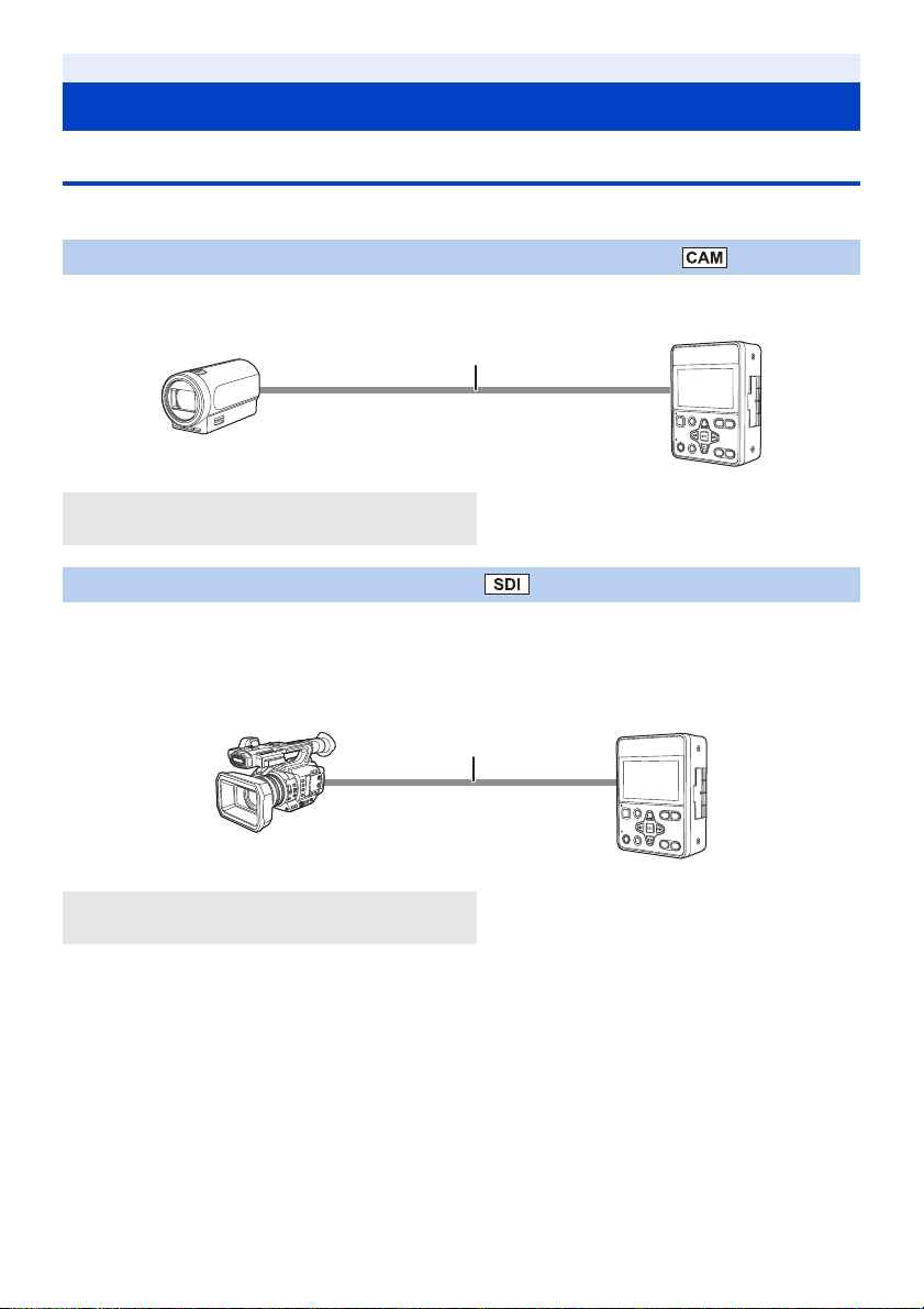
Connecting to the Camera Head (optional) to record (CAM Mode)
It is possible to connect to the Camera Head and record onto an SD card.
≥ It is possible to manually operate Camera Head camera functions such as Zoom, Focus, and IRIS with this unit.
A Camera Head
B Camera head option cable (optional)
Input SDI to this unit and record (SDI Mode)
It is possible to connect to external devices (HD camera recorder, HD information camera system etc.) equipped with
an HD-SDI output terminal and record video signals, audio signals, time code (SLTC) etc. on the SD card.
≥ This is suitable for long-term backup recording etc.
≥ Recording start and stop operation of this unit can be performed from some camera recorders. (When SDI input is
selected)
C Camera recorder (SDI output device)
D BNC cable
* To connect to the SDI IN terminal or SDI OUT terminal, use a double-shielded BNC cable equivalent to 5C-FB
(commercially-available).
*
- 19 -
Page 20

Linking to external devices
Connection to a PC (USB connection)
Transfer data (files) to perform nonlinear editing on another device (PC, etc.).
≥ This unit supports USB 2.0.
A SD card
*1 SD cards are optional and not supplied with this unit.
*2 A USB 2.0 cable is not supplied with this unit. Use a commercially available cable compatible with the USB 2.0
standard. Connect the miniB connector to this unit.
*1
B USB 2.0 cable (A-miniB type)
*2
C PC
Connection to external monitor/external device (such as a recorder)
Connect to an external monitor or an external device (such as a recorder) and output video.
A Camera recorder
(SDI output device)
B Camera Head
*3 Use a commercially-available High Speed HDMI cable. If possible, we recommend using a cable with a length of
3 m (9.84 feet) or less.
*4 To connect to the SDI IN terminal or SDI OUT terminal, use a double-shielded BNC cable equivalent to 5C-FB
(commercially-available).
When connecting with an HDMI cable using an HDMI-to-DVI converter, etc., be sure to connect the HDMI
cable to the connector of this unit last.
Connecting the HDMI cable to the connector of this unit first may result in malfunction.
C HDMI cable
D BNC cable
*3
*4
E External monitor/
external device such as a recorder
≥ When connecting in SDI Mode, it is possible to change the output method to the external device by setting
[SDI MODE SEL].
≥ The video signal of the SDI output may stop temporarily when the HDMI cable is disconnected and connected or the
connected monitor is replaced, for example.
- 20 -
Page 21
Network connection
ヒビヷ リワ
ロモワ ンヴノフビビ ヱンユヷリユヸ
ヤヤヶ
ヴリヨワモロチヨワュ
SIGNAL GND
TALLY/GPI
TO PAN/TILT HEAD
54321
SV
POWER
ON
BOOT
NM
12V IN
LAN
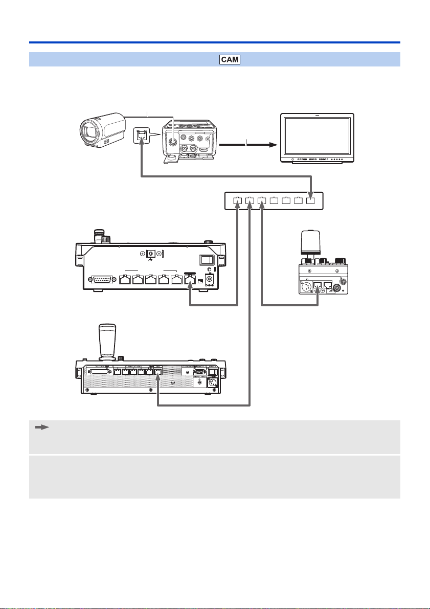
Connection with remote camera controller
This unit supports the remote camera controllers AW-RP50/AW-RP120 and the remote operation panel AK-HRP200.
(Connection example)
: LAN cable
A Camera head option cable
B HDMI cable/BNC cable
1 AG-MDR25
2 Camera Head
3 Switching hub
4 Remote camera controller AW-RP50
*1 The illustration of the supplied AC adaptor is omitted.
*1
*1
5 Remote camera controller AW-RP120
6 Remote Operation Panel AK-HRP200
7 External monitor
*2 The illustration of the external DC power supply is omitted.
≥ This unit will automatically recognize straight cables and crossover cables connected to the LAN terminal.
- 21 -
*2
*2
Page 22

Connection to PC/mobile terminal
This unit can display an IP image on a PC connected to the network via wired LAN or a mobile terminal connected via
a wireless access point.
(Connection example)
ヴユヵ
ヴユヵ
: LAN cable
: BNC cable
1 AG-MDR25
2 Camera Head or SDI output device
3 AG-MDR25
output device
4 Switcher
5 External monitor
*1 The cable to be connected and the terminal where the cable plugs in differ depending on the connected device
(Camera Head/SDI input device).
*2 The illustration of the supplied AC adaptor is omitted.
*3 The illustrations of the Camera Head and SDI output device are omitted.
≥ This unit will automatically recognize straight cables and crossover cables connected to the LAN terminal.
*2
*3
connected to the Camera Head/SDI
A Camera head option cable or BNC cable
B LAN cable (straight cable)
6 Remote camera controller AW-RP50
7 Switching hub
8 PC
9 Wireless access point
: Mobile terminal
*1
*2
- 22 -
Page 23
Preparation
1
25 26 2424
2
8
10
34 56
11 12 13 14 15 16
7
9
17 18
21
22
23
19 20
27
28
29
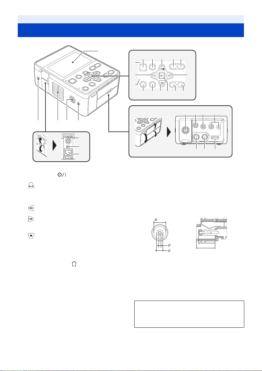
Names and Functions of Main Parts
1 LCD monitor (Touch screen) (l 36)
2 Power button [ ] (l 32)
3 Menu button [MENU] (l 35)
4 button
5 AUDIO MON/ADV j button
6 AUDIO MON/ADV i button
7 Status indicator (l 32)
8 button
9 Tally lamp
10 button
11 REC/PAUSE button (l 42)
12 SHIFT button (l 77)
13 button
14 SET button
15 MODE button (l 34)
16 User 1 button [USER1] (l 67)
17 CAMERA terminal (l 30)
18 Headphone terminal [ ] (l 82, 93)
19 MIC/LINE IN input terminal (l 61)
20 Camera remote terminal [CAM REMOTE] (l 93)
≥
FOCUS IRIS terminal (3.5 mm (0.14q) diameter mini jack)
≥ ZOOM S/S terminal (2.5 mm (0.1 q) diameter super
mini jack)
21 SDI IN terminal [HD SDI IN] (l 31)
22 SDI OUT terminal [HD SDI OUT] (l 94)
23 HDMI OUT terminal [HDMI OUT] (l 94)
24 Multipurpose screw hole
≥ M3 (3 mm (0.1 q) diameter) type screws with lengths
up to 8 mm (0.3 q) can be used for the four screw holes
on the side of this unit.
≥ When using screws, do not apply excessive force.
Also, if you use a M3 (3 mm (0.1 q) diameter) type
screw longer than 8 mm (0.3 q) in length, this unit may
be damaged.
25 Exhaust opening (cooling fan) (l 40)
26 Speaker
27 DC input terminal [DC IN] (l 25, 227)
≥ Connect the DC 12 V power source. When the voltage
drops to approximately 10 V, if the battery is not
connected, the unit will turn off automatically. After
that, even if the power supply voltage recovers, it will
not turn back on automatically. Please press the power
button for at least 2 seconds to turn on the unit.
5.9
[7/32]
0
[1/8]
-0.2
3
+0.1
0
1.05
Units: mm [inch]
28 USB 2.0 terminal (l 107)
29 LAN connector for IP control [LAN ACT/LINK]
≥ This LAN connector (RJ-45) is connected when
exercising IP control over the unit from an external
device. Use a cable with the following specifications for
the connection to the LAN connector:
LAN cable* (category 5 or above), max. 100 meters
(328 feet)
* Use of an STP (shielded twisted pair) cable is
recommended.
- 23 -
[1/32] [11/32]
8
9
0
-0.2
0.1
[5/16]
Page 24

30 Inlet (cooling fan) (l 40)
24 2430 31 32
38 38
33 35 3634 37
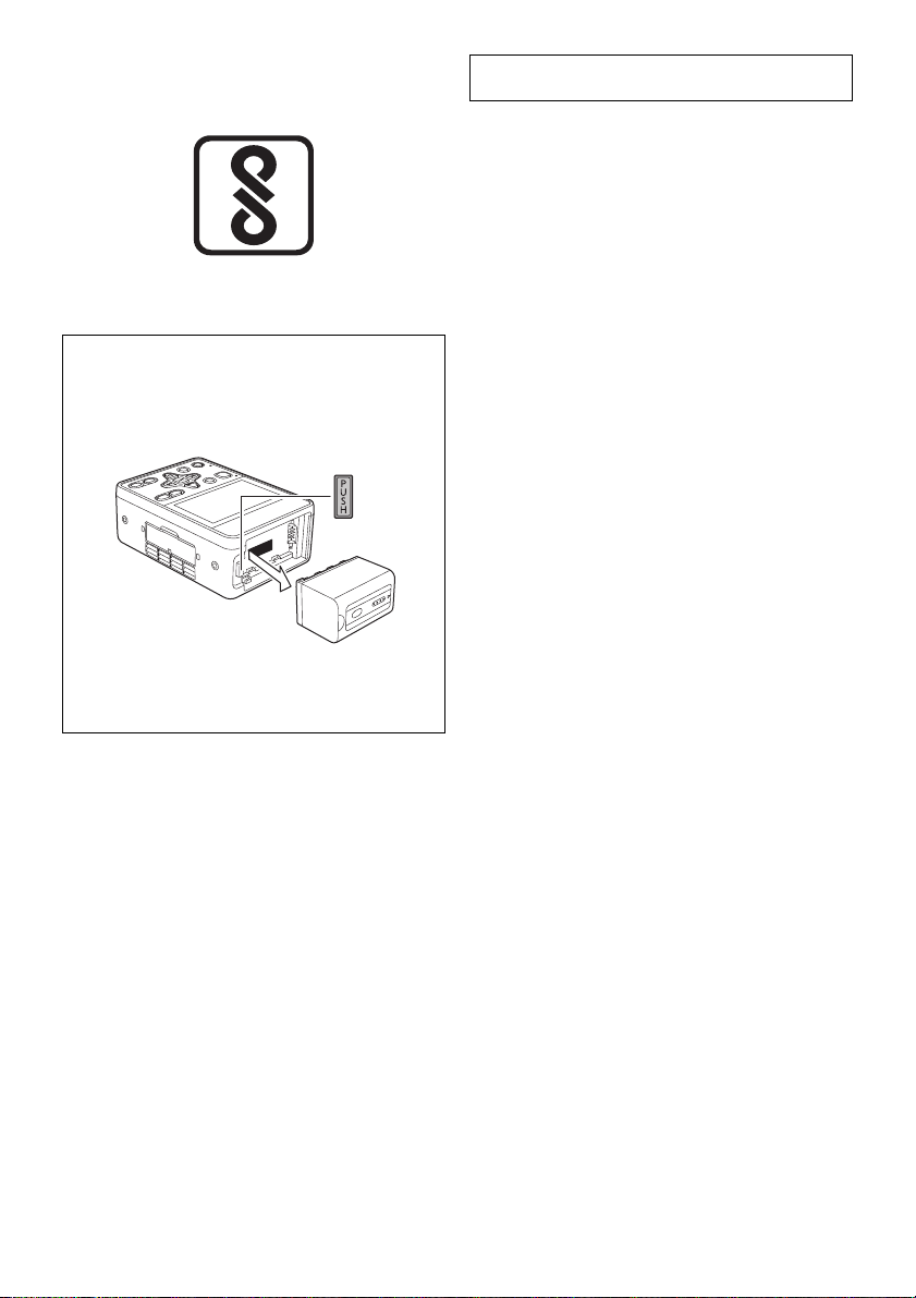
31 Battery release button [PUSH] (l 26)
32 Battery holder (l 26)
33 SD Card slot cover (l 29)
34 Access lamp (card 1) (l 29)
35 Card slot 1 (l 29)
36 Card slot 2 (l 29)
37 Access lamp (card 2) (l 29)
38 Setting legs
- 24 -
Page 25
Preparation
Power supply
Using the AC adaptor
The unit is in the standby condition when the AC adaptor is connected. The primary circuit is always “live” as long as
the AC adaptor is connected to an electrical outlet.
Important:
≥ Use the supplied AC adaptor. Do not use the AC adaptor of another device.
≥ Do not use the AC cable with any other equipment as it is designed only for this unit. Also, do not use the
AC cable from other equipment with this unit.
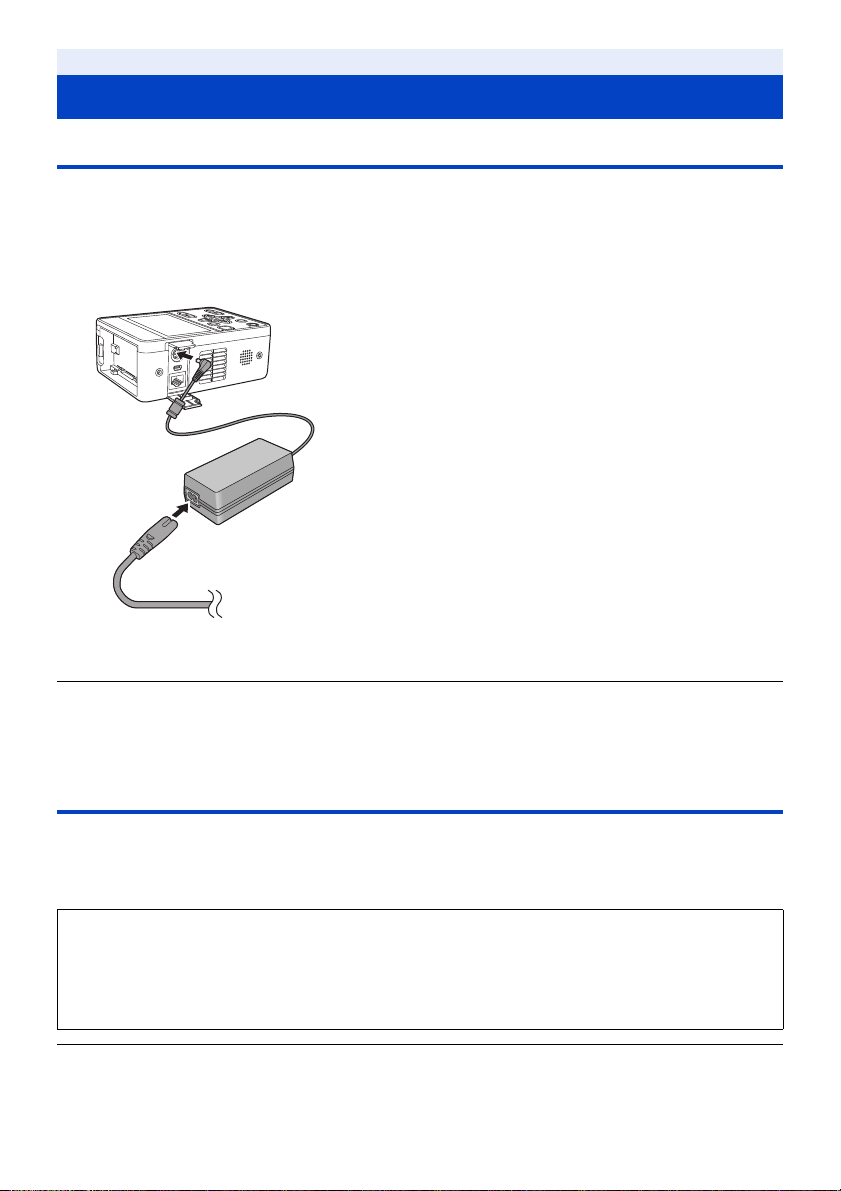
1 Connect the AC cable to the AC adaptor and the
AC outlet.
2 Connect the AC adaptor to the DC input terminal
[DC IN].
≥ When disconnecting the AC adaptor, be sure to press and hold
the power button to turn off the unit, and check that the status
indicator has gone out before removing it. (l 32)
≥ Insert the plugs as far as they will go.
≥ Even when you use the AC adaptor for recording images, keep the battery connected. This allows you to continue
the recording even if a power failure occurs or the AC adaptor is unplugged from the AC outlet by accident.
≥ This unit consumes a small amount of power even when turned off. When leaving the product unused for a long
time, disconnect the AC adaptor from the AC outlet for power saving.
Using the battery
∫ About batteries that you can use with this unit (as of April 2017)
The battery that can be used with this unit is VW-VBD58/AG-VBR59/AG-VBR89/AG-VBR118.
≥ The AG-VBR59/AG-VBR89/AG-VBR118 supports quick charging.
≥ It is recommended to charge with the AG-BRD50 battery charger that supports fast charging.
It has been found that counterfeit battery packs which look very similar to the genuine product are made
available to purchase in some markets. Some of these battery packs are not adequately protected with
internal protection to meet the requirements of appropriate safety standards. There is a possibility that
these battery packs may lead to fire or explosion. Please be advised that we are not liable for any accident
or failure occurring as a result of use of a counterfeit battery pack. To ensure that safe products are used
we would recommend that a genuine Panasonic battery pack is used.
≥ For information on how to charge the battery, refer to the Operating Instructions for the battery charger.
- 25 -
Page 26
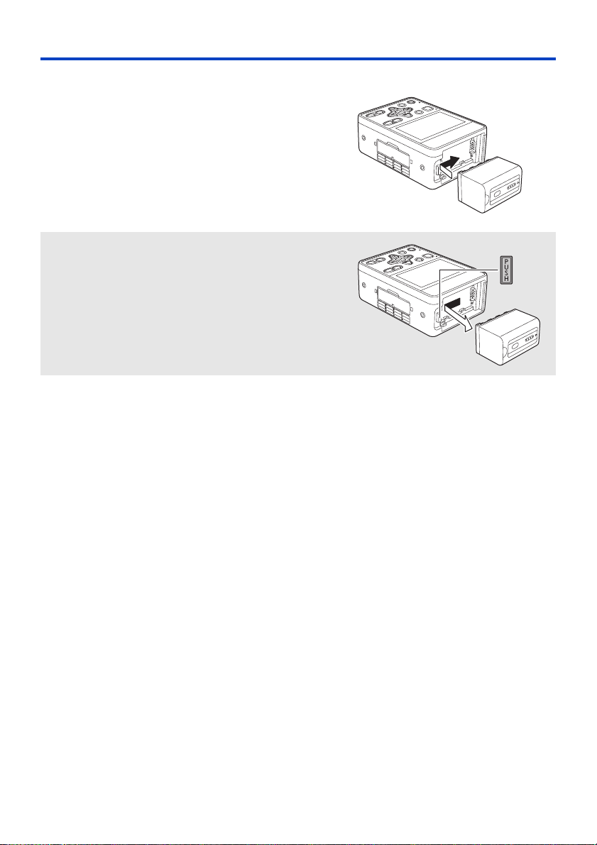
Inserting/removing the battery
Install the battery by inserting it in the direction
shown in the figure.
≥ Insert the battery until it clicks and locks.
Removing the battery
Turn off the unit by pressing and holding the power button until the
status indicator is turned off, and remove while holding with hand
so it will not fall.
While pressing the battery release button, remove the battery.
- 26 -
Page 27

Charging and recording time
Charging/Recording time
Battery model
number
AG-VBR59
(optional)
VW-VBD58
(optional)
AG-VBR89
(optional)
AG-VBR118
(optional)
≥ The charging time is the time when the battery charger AG-BRD50 is used.
≥ The times given apply when the ambient operating temperature is 25 oC (77 oF) and the relative operating humidity
is 60%. Charging time may be longer at other temperatures and humidity levels.
≥ The continuous recordable time given applies under the conditions below. The time becomes shorter under other
conditions.
j (CAM Mode)
Recording is performed with [REC FORMAT] set to [PH 1080/59.94i] or [PH 1080/50.00i] when the unit is
connected to the Camera Head with a Camera head option cable (AG-C20003G [3 m] (118-1/8 q)) and not
connected to an external device.
j (SDI Mode)
Recording is performed with [REC FORMAT] set to [PH 1080/59.94i] or [PH 1080/50.00i].
≥ “h” is an abbreviation for hour, “min” for minute and “s” for second.
≥ These times are approximations.
≥ The indicated charging time is for when the battery has been discharged completely. Charging time and
recordable time vary depending on the usage conditions such as high/low temperature.
≥ The batteries heat up after use or charging. This is not a malfunction.
≥ Use of the optional battery charger AG-B23 (DE-A88), which does not support fast charging, will result in a longer
charging time.
Voltage/Capacity
(minimum)
7.28 V/5900 mAh 3 h 20 min
7.2 V/5800 mAh 5 h 20 min
7.28 V/8850 mAh 4 h
7.28 V/11800 mAh 4 h 40 min
Charging
time
System Frequency
setting (l 212)
59.94 Hz 3 h 6 h 40 min
50.00 Hz 3 h 10 min 6 h 50 min
59.94 Hz 2 h 50 min 6 h 25 min
50.00 Hz 3 h 6 h 30 min
59.94 Hz 4 h 35 min 10 h 10 min
50.00 Hz 4 h 45 min 10 h 20 min
59.94 Hz 6 h 5 min 13 h 25 min
50.00 Hz 6 h 20 min 13 h 40 min
Continuously recordable time
CAM Mode SDI Mode
Battery capacity indication
≥ The display changes as the battery capacity reduces. #### If the battery
discharges, then will flash red.
≥ Depending on the menu setting, the battery capacity indication is not displayed (l 225)
[DISP SETUP] # [CARD & BATTERY]
- 27 -
Page 28

Preparation
Preparation of SD cards
The unit can record motion pictures or still pictures to an SD card.
Cards that you can use with this unit
≥ The cards that you can use are correct as of April 2017.
≥ We recommend that you use a Panasonic Memory Card.
Card type Capacity
SDHC Memory Card 4GB to 32GB
SDXC Memory Card 48 GB to 128 GB
≥ We do not guarantee the operation of SD cards other than the ones above.
≥ 4 GB or more Memory Cards that do not have the SDHC logo or 48 GB or more Memory Cards that do not have
the SDXC logo are not based on SD Memory Card Specifications.
≥ When the write-protect switch A on SD card is locked, no recording, deletion or editing will be
possible on the card.
≥ Keep the Memory Card out of reach of children to prevent swallowing.
64
∫ About the Speed Class ratings for recording motion pictures
≥ The required card differs depending on the setting of [PRIORITY MODE].
Use a card that meets the following ratings of the SD Speed Class.
Use of a non-compatible card may cause recording to stop suddenly.
≥ SD Speed Class is the speed standards regarding continuous writing. To check the class, see the labelled side, etc.
of the card.
PRIORITY MODE Speed Class ratings Label examples
REC/PB(4K) Class10 or more
REC/PB Class4 or more
- 28 -
Page 29
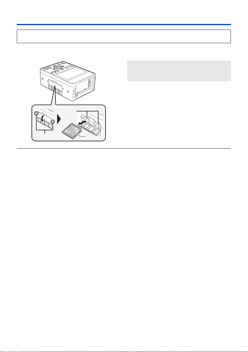
Inserting/removing an SD card
When using an SD card for the first time, it is necessary to format the SD card. (l 41) When the SD card is
formatted, all of the recorded data is deleted. Once the data is deleted, it cannot be restored.
Caution:
Check that the access lamp has gone off.
Access lamp A
≥ When this unit is accessing the SD card, the
access lamp lights up.
1 Open the SD card slot cover and insert
(remove) the SD card into (from) the card
slot B.
≥ One SD card can be inserted into each of the card slot
≥ Do not touch the terminals on the back of the SD card.
≥ Do not apply strong shocks, bend, or drop the SD card.
≥ Electrical noise, static electricity or the failure of this unit or the SD card may damage or erase the data stored on the
SD card.
≥ When the card access lamp is lit, do not:
j Remove the SD card
j Turn the unit off
j Insert and remove the USB Cable
j Expose the unit to vibrations or shock
Performing the above while the lamp is on may result in damage to data/SD card or this unit.
≥ Do not expose the terminals of the SD card to water, dirt or dust.
≥ Do not place SD cards in the following areas:
j In direct sunlight
j In very dusty or humid areas
j Near a heater
j Locations susceptible to significant difference in temperature (condensation can occur.)
j Where static electricity or electromagnetic waves occur
≥ To protect SD cards, return them to their cases when you are not using them.
≥ About disposing of or giving away the SD card. (l 12)
1 and the card slot 2.
≥ Face the label side C in the direction shown in the
illustration and press it straight in as far as it will go.
≥ Press the center of the SD card and then pull it straight
out.
2 Securely close the SD card slot cover.
- 29 -
Page 30
Preparation
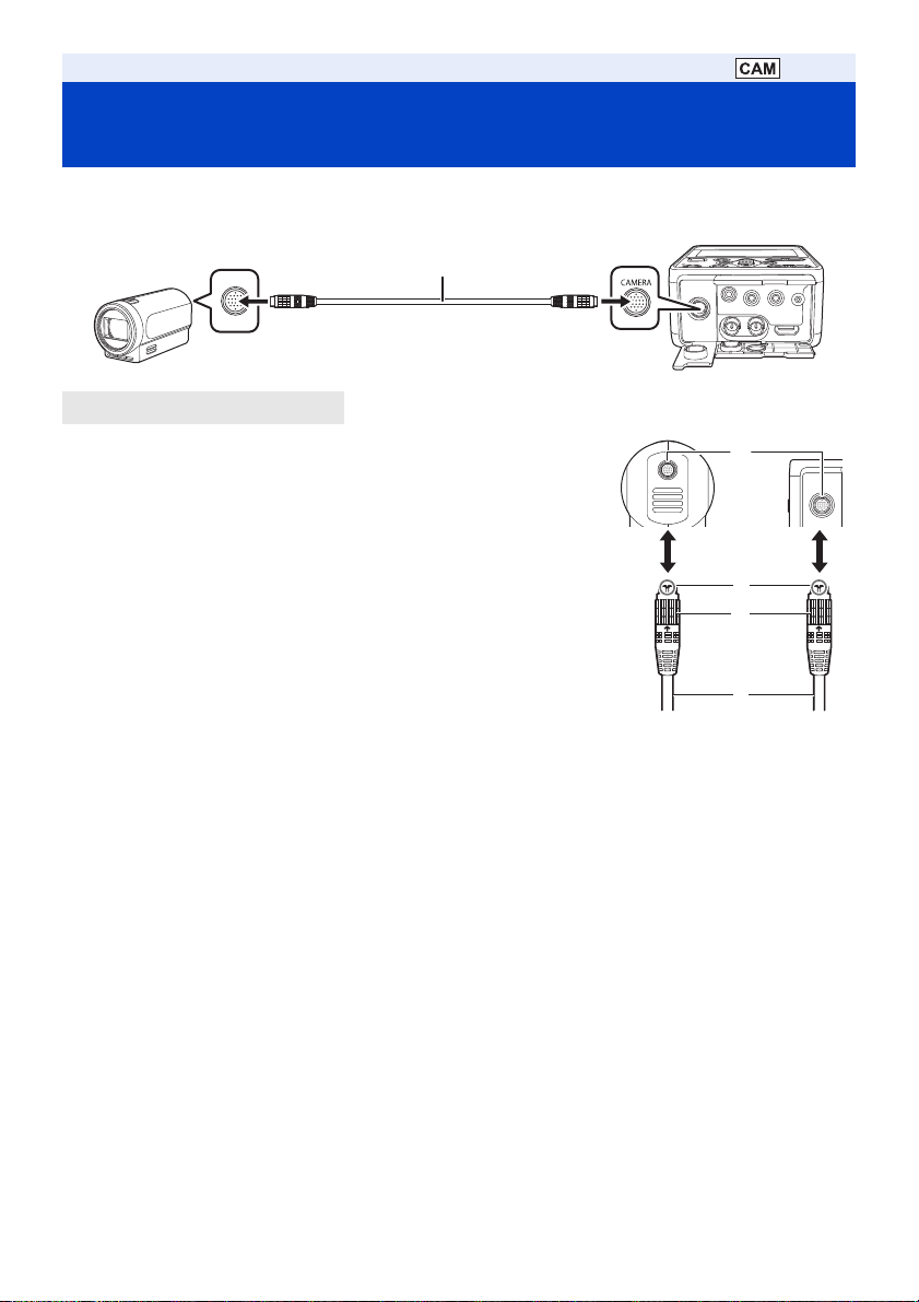
Connecting this unit to the Camera Head (CAM Mode)
∫ Attaching the Camera head option cable (optional)
Be sure to turn off the unit before attaching the Camera head option cable.
A Camera head option cable
1 Insert Camera head option cable D into this unit’s CAMERA
terminal and the Camera Head connecting terminal.
≥ Align notch A of the terminal of the Camera head option cable with guide B
of the connecting terminal to insert.
2 Turn the Camera head option cable terminal ring C
clockwise.
≥ Fix firmly so that there is no looseness.
≥ This unit will start up in the CAM Mode when it is turned on after connection.
The Camera Head is turned on and recording is possible.
∫ Removing the Camera head option cable
Be sure to turn off this unit before removing the Camera head option cable.
1 Loosen the ring on the terminal of the Camera head option cable by turning it
counterclockwise.
2 Hold the ring on the terminal of the Camera head option cable and pull it straight out.
- 30 -
Page 31

Preparation
Input SDI to this unit (SDI Mode)
A Camera recorder (SDI output device)
B SDI OUT terminal
C BNC cable (commercially-available)
Connect the SDI output device to this unit with a BNC cable.
≥ Use the 5C-FB compatible double shielded cable for the BNC cable (commercially available product) to connect to
the SDI IN terminal and the SDI OUT terminal.
≥ This unit will start up in the SDI Mode when it is turned on as follows.
j When the power button is pressed and held for 2 seconds or longer when the Camera Head is not connected
(l 32)
j When the power button is pressed and held for 2 seconds or longer while the USER1 button is pressed and held
∫ Functions that cannot be set in the SDI Mode
The following functions cannot be set on this unit in the SDI Mode. Set on the SDI output device side.
j Switching Recording Mode (l 44)
j Adjustment of picture quality (l 45)
j Zoom (l 47)
j Image stabilization (l 48)
j Focus (l 49)
j White balance (l 53)
j Iris (l 55)
j Gain (l 57)
j Shutter speed (l 59)
≥ There are other USER button functions and menus that cannot be used in the SDI Mode. For details, refer to the
following pages.
j Functions of the USER button (l 68)
j Using the SHIFT button (l 77)
j Menu structure (l 195)
IN
HD SDI
- 31 -
Page 32

Preparation
Turning the unit on/off
≥ The method for turning on the unit depends on the setting of [POWER UP OPTION]. (l 227)
Press power button B for 2 seconds or more to turn on the unit.
To turn off the unit
SET
A The status indicator lights on.
≥ Operation Mode icon ( / ) is displayed on the screen.
j (CAM Mode): Displayed when the unit is turned on while connected to the Camera Head.
j (SDI Mode): Displayed when the unit is turned on while not connected to the Camera Head. It is also
≥ This unit may automatically reboot when turned on in the following cases.
j When turned on for the first time after connecting this unit with the Camera Head
j When turned on after connecting this unit with another Camera Head
The setup of the [
≥ When in SDI Mode, to turn on the unit again after [ECONOMY (BATT)] or [ECONOMY (AC)] have worked, press the
power button for 2 seconds or longer to turn on the unit. (l 227)
≥ Connecting or removing the Camera Head with this unit turned on may cause this unit and the Camera Head to
malfunction. Be sure to turn off this unit before connecting/disconnecting the Camera Head to/from it.
≥ If the camera head is faulty, such as a fault or a cable disconnection, [System error. Please turn off.] is displayed on
the LCD monitor, recording is not possible.
≥ If you turn off the unit without pressing the power button by, for example, disconnecting the AC adaptor from the AC
outlet, the unit will not memorize the zoom and focus positions, iris and gain values, and shutter speed at that point
in time. To have the unit remember the last-used positions and values when it is turned on, follow either of the steps
below to have it memorize them.
j Turn off the unit by pressing the power button.
j Switch to Playback Mode.
displayed if the unit is turned on while pressing and holding the USER1 button after
connecting the Camera Head.
SCENE FILE] menu saved in the Camera Head is reflected to this unit after the reboot.
Press the power button for 2 seconds or more.
The status indicator goes off.
- 32 -
Page 33

Preparation
ヮユワヶ
Selecting a mode
Switching between the CAM Mode and the SDI Mode
Always turn off this unit and turn it on again when switching between the SDI Mode and the CAM Mode.
≥ Connect this unit and the Camera Head when switching to the CAM Mode. (l 30)
≥ To boot this unit in the SDI Mode with the Camera Head connected, turn on while pressing and holding the USER1
button.
Switching the priority mode
By switching [PRIORITY MODE], this unit can operate according to various applications.
The items that can be set vary depending on the device to be connected. (CAM Mode: l 30/SDI Mode: l 31)
Select the menu. (l 35)
: [RECORD SETUP] # [PRIORITY MODE] # desired setting
±: Recording is possible/s: Recording or distribution is not possible
[PRIORITY MODE]
setting
REC/PB(4K)
REC/PB
*1 Clips recorded on an SD card can be downloaded to a PC and transferred to an FTP server.
*2 On the Live screen of this unit, 4K image in the H.264 format cannot be displayed. To display 4K images, please
use a 4K image-compatible external device or external software.
*3 This unit is not compatible with clips recorded with AVCHD.
*1
*1
*2
IP(4K)
IP s
Record to SD card
± (MP4*3) s
± (AVCHD)
s
H.264 JPEG
IP streaming
Distribution of 1ch is
possible
Distribution of 2ch is
possible
Distribution of 1ch is
possible
≥ [IP(4K)] and [REC/PB(4K)] are not available in SDI Mode.
- 33 -
Page 34

Switching between Recording Mode and Playback Mode
ヴユヵ
ヮヰュユ
When [PRIORITY MODE] is set to [REC/PB] or [REC/PB(4K)], press the MODE button to switch between Recording
Mode and Playback Mode.
≥ If set to [IP], [IP(4K)], even if the MODE button is pressed, this unit will not enter Playback Mode.
Press the MODE button A to switch between Recording Mode and Playback Mode.
Recording Mode (l 42) The recording screen is displayed. You can
Playback Mode (l 84) The thumbnail screen for playback is displayed.
≥ When you turn on this unit, it starts up in Recording Mode.
record motion pictures.
You can play back clips and still pictures.
∫ Switching between Recording Mode and Standby Mode
When [PRIORITY MODE] is set to [IP] or [IP(4K)], press the MODE button to switch between Recording Mode and
Standby Mode.
≥ In Standby Mode, this unit appears as follows.
j The status indicator flashes slowly.
j Turn off the LCD monitor of this unit.
j This unit’s SDI output, HDMI output and IP distribution stops.
j In the CAM Mode, functions other than the Camera Head network function and the cooling fan stop.
- 34 -
Page 35

Preparation
ヴユヵ
ヮユワヶ
Using the menu screen
Menu setting by button operation
1 Press the MENU button .
2 Press the /// buttons to move the cursor to the menu, and press the SET button
to select.
3 Place the cursor on [EXIT] and press the SET button to finish the menu setting.
∫ About page switching
It is not possible to select the / / / icon with button operation.
If the cursor is on the top item, press the button, or if the cursor is on the bottom item, press the button to
switch the page.
∫ To adjust the numerical value by button operation
In the menu for setting the numerical value, after selecting the numerical display part, press the / / /
buttons to adjust.
ヮユワヶ
(For example, when adjusting the brightness with [LCD SET])
1 Place the cursor on the numerical display A and press the SET
button to select.
2 Press the / buttons to adjust the value.
≥ When the SET button is pressed, the adjusted value is set.
≥ There is also a menu to adjust by pressing the / buttons.
- 35 -
Page 36

Menu setting by touch screen operation
1 Press the MENU button .
ヮユワヶ
2 Touch the top menu A.
3 Touch the submenu B.
≥ Next (Previous) page can be displayed by touching
/.
4 Touch the desired item to enter the setting.
5 Touch [EXIT] to exit the menu setting.
How to use the touch screen
You can operate by directly touching the LCD monitor (touch screen) with your finger.
∫ Touch
Touch and release the touch screen to select icon or picture.
≥ Touch the center of the icon.
≥ Touching the touch screen will not operate while you are touching
another part of the touch screen.
∫ Slide while touching
Move your finger while pressing on the touch screen.
∫ About the operation icons
///:
Touch when changing a page or performing settings.
[RETURN]:
Returns you to the previous screen.
≥ Do not touch the LCD monitor with hard pointed tips, such as ball point pens.
- 36 -
Page 37

Preparation
ヮユワヶ
ヮユワヶ
Setting date and time
When this unit is turned on, the message [SET TIME ZONE AND DATE/TIME] may appear.
To make these settings, select [YES], and follow the instructions from Step 2-3 of the time zone setting procedure.
Time zone
Time difference from the Greenwich Mean Time can be set.
1 Select the menu.
: [OTHER FUNCTION] # [TIME ZONE]
2 Touch / and set the region to record.
3 Touch [ENTER] to complete the setting.
≥ If the [CLOCK SET] screen appears, perform [CLOCK SET].
≥ Touch the MENU button to close the menu screen.
≥ When the time zone setting is changed, the date/time setting of the unit also changes automatically.
Clock setting
1 Select the menu.
: [OTHER FUNCTION] # [CLOCK SET]
2 Touch the date or time to be set, then set the desired value
using / .
≥ The year can be set between 2000 and 2035.
3 Touch [ENTER] to complete the setting.
≥ Touch the MENU button to close the menu screen.
≥ The date and time function is driven by a built-in lithium battery.
≥ If the time display becomes [- -], the built-in lithium battery needs to be charged. To recharge the built-in lithium
battery, connect the AC adaptor or attach a charged battery to this unit. Leave the unit as it is for approx. 24 hours
and the battery will maintain the date and time for approx. 6 months. (The battery is still being recharged even if the
unit is off.)
≥ The way that time is displayed can be changed in the menu settings. (l 225)
[DISP SETUP] # [DATE/TIME] or [DATE FORMAT]
- 37 -
Page 38

∫ Time zone table
Time
difference
0:00 London, Casablanca r3:30 Te hr a n
s1:00 Azores r4:00 Dubai, Abu Dhabi
s2:00 Fernando de Noronha r4:30 Kabul
s3:00 Rio de Janeiro, Sao Paulo, Buenos Aires r5:00 Islamabad, Karachi, Male
s3:30
s4:00 Manaus, La Paz r5:45 Kathmandu
s4:30 Caracas r6:00 Dhaka
s5:00 Toronto, New York, Miami, Lima r6:30 Yangon
s6:00 Chicago, Houston, Mexico City r7:00 Bangkok, Jakarta
s7:00
s8:00 Vancouver, Seattle, Los Angeles r9:00 Seoul, Tokyo
s9:00 Alaska, Anchorage r9:30 Adelaide
s10:00 Hawaii, Honolulu, Tahiti r10:00 Guam, Sydney
s11:0 0 Midway Islands r11:00 Solomon Islands, New Caledonia
r1:00 Berlin, Paris, Rome, Madrid r12:00 Fiji, Auckland, Wellington
r2:00 Helsinki, Athens, Cairo, Johannesburg r12:45 Chatham Islands
r3:00 Moscow, Kuwait, Riyadh, Nairobi
Newfoundland
Denver, Phoenix
Region
Time
difference
r5:30
r8:00
Region
Delhi, Kolkata, Mumbai, Chennai,
Colombo
Beijing, Hong Kong, Kuala Lumpur,
Singapore
- 38 -
Page 39

Preparation
ヮユワヶ
ヮユワヶ
Adjusting the LCD monitor
≥ These settings will not affect the images actually recorded.
[POWER LCD]
This makes it easier to view the LCD monitor in bright places including outdoors.
Select the menu.
: [DISP SETUP] # [POWER LCD] # [+1] (Makes brighter)/[0] (Normal)/[-1] (Makes less bright)
[LCD SET]
It adjusts brightness and color density on the LCD monitor.
1 Select the menu.
: [DISP SETUP] # [LCD SET]
2 Touch the desired setting item.
[COLOR]: Color level of the LCD monitor
[BRIGHTNESS]: Brightness of the LCD monitor
[CONTRAST]: Contrast of the LCD monitor
3 Touch / to adjust settings.
≥ You can select a value between s16 and r16.
4 Touch [RETURN].
≥ Touch [EXIT] to exit the menu screen.
Reversing the display on the LCD monitor
The LCD monitor can be displayed reversed vertically and horizontally.
Press the USER button assigned as <LCD REVERSE>.
≥ For how to assign functions to the USER buttons, refer to page 66.
≥ The reversed display and normal display switches every time the button is pressed.
≥ The reversed display also reverses the horizontal and vertical directions of the / / / buttons, except
for the following functions.
j Zoom control with the / buttons
j Functions that operate when one of these buttons and the SHIFT button are pressed simultaneously (l 77)
≥ Reversed display can be switched by setting the menu.
[DISP SETUP] → [LCD REVERSE] → [ON] (reversed display)/[OFF] (normal display)
- 39 -
Page 40

Recording
ヮユワヶ
Before recording
≥ When recording, make sure your footing is stable and there is no danger of colliding with another person or object.
≥ When you are outdoors, record pictures with the sunlight behind you. If the subject is backlit, it will become dark in
the recording.
≥ For stable images, it is recommended to use a tripod whenever possible.
≥ Do not block the air inlet or exhaust opening of the cooling fan of this unit or the Camera Head with your hands, etc.
∫ To fix the Camera Head to a tripod
Attach the tripod to the tripod mounting hole of the Camera Head.
A Tripod mounting hole
≥ The depth of the screw hole in the tripod mounting hole is 6 mm (0.24 q). When attaching this unit to a tripod or the
like, do not tighten the screw with excessive force. Also, if screws other than 1/4-20 UNC type are used, the Camera
Head may be damaged.
≥ When fixing to something other than a tripod, pay attention to the following points.
j Use the tripod mounting hole to fix securely.
j Do not block the Camera Head inlet, exhaust opening or built-in microphone with fixing parts.
≥ If the Camera Head is held as shown below, a heavy load will be applied to the cable and the terminal, which may
cause damage. Also, be careful as the cable may come off and the Camera Head may fall or collide with the
surrounding walls and be damaged.
B Hold the cable only or fix C Hold the cable only and suspend this unit
∫ To record reversed vertically and horizontally
The recorded image can be reversed vertically and horizontally by setting [SCAN REVERSE] when the Camera Head
is connected. Lch/Rch of the built-in microphone will also switch.
≥ Use this function for ceiling mount (upside down) installation.
Select the menu.
: [SW SETUP] # [SCAN REVERSE] # [ON]
- 40 -
Page 41

Recording
ヮユワヶ
ヮユワヶ
ヮユワヶ
ヮユワヶ
Selecting a media to record
You can specify the card slot to which motion pictures are to be recorded.
Select the menu.
: [RECORD SETUP] # [MEDIA SELECT] # [SD CARD 1]/[SD CARD 2]
≥ You can also change the card slot used for motion picture recording by pressing the USER button to which <SLOT
SEL> is registered or touching the applicable USER button icon while recording is paused. (l 66)
≥ If [PRIORITY MODE] is [IP] or [IP(4K)], it cannot be set.
Formatting media
If you use the SD cards for the first time for recording with this unit, format the cards.
Please be aware that if a medium is formatted, then all the data recorded on the medium will be erased and cannot be
restored. Back up important data on a PC etc. (l 106)
≥ When using two SD cards, format both SD cards.
1 Select the menu.
: [CARD FUNCTION] # [FORMAT CARD]
2 Touch [SD CARD 1] or [SD CARD 2].
≥ When formatting is complete, touch [EXIT] to exit the message screen.
≥ Do not turn this unit off or remove the SD card, while formatting. Do not expose the unit to vibrations or shock.
Use this unit to format media.
Do not format an SD card using any other equipment such as a PC. Otherwise it may not be possible to use
the card on this unit.
System frequency Selection
Set the system frequency of this unit.
Select the menu.
(In Recording Mode)
: [RECORD SETUP] # [SYSTEM FREQ] # desired setting
(In Playback Mode)
: [OTHER FUNCTION] # [SYSTEM FREQ] # desired setting
[59.94Hz]: The system frequency for NTSC television broadcasting system regions
[50.00Hz]: The system frequency for PAL television broadcasting system regions
≥ After you have changed the system frequency, this unit will be restarted automatically.
≥ By default, the system frequency is set to the broadcasting system of the region where this product was purchased.
≥ AG-MDR25P: This function’s default setting is [59.94Hz].
AG-MDR25E: This function’s default setting is [50.00Hz].
≥ When recording [PRIORITY MODE] with [REC/PB], clips with different system frequencies cannot be recorded on
one SD card. Please prepare an SD card for each system frequency.
- 41 -
Page 42

Recording
ヴユヵ
ンユヤバ
ヱモヶヴユ
REC
TC 00:00:00TC 00:00:00.0000TC 00:00:00.00
29.97p29.97p
50M50M
R 1h20mR 1h20mR 1h20m
R 1h20mR 1h20mR 1h20m
RELAYRELAY
Record on SD card
1 Set [PRIORITY MODE] to [REC/PB] or [REC/
PB(4K)] to switch to Recording Mode. (l 33, 34)
2 Press REC/PAUSE button A to start recording.
≥ When recording starts, REC (red) appears on the screen and the
tally lamp lights up.
≥ Press again to stop recording.
∫ Screen indications in the Recording Mode
TC 00:00:00.00 Counter display (l 63)
/ (White) Card slot number
R1h20m
50M Bit rate (l 213)
29.97p Frame rate (l 213)
Approximate remaining recordable time
≥ When the remaining time is less than 1 minute, R 0h00m flashes red.
Card slot at the recording destination (l 41)
Recording format (l 213)
MP4 recording
≥ To change the recording method, change [PRIORITY MODE] or [REC FORMAT]. (l 33, 213)
≥ The images recorded between pressing the recording start/stop button to start recording and pressing it again to
pause recording become one clip.
≥ The clip is automatically split when the file size of the recorded clip exceeds any of the values below, or the
recording time exceeds the length below. (Recording will continue)
AVCHD clip Approx. 10 hours
MP4 clip (when using an SDHC Memory Card) Approx. 4 GB
MP4 clip (when using an SDXC Memory Card) Approx. 3 hours
* AVCHD files are automatically divided when their file size exceeds approx. 4 GB.
≥ When MP4 clips that were generated by automatic splitting are played back in succession, the changeover between
them may not be smooth.
≥ Recording stops momentarily when the continuous recording time reaches approx. 10 hours, and then it resumes
automatically after a few seconds.
Nothing will be recorded for a few seconds until the recording resumes.
- 42 -
*
Page 43

≥ (Maximum recordable scenes of a single SD card)
PRIORITY MODE REC/PB(4K) REC/PB
Recordable clips Approx. 89100 Approx. 3900
Different dates (l 89) Approx. 900 Approx. 900
≥ The maximum number of recordable clips and the maximum number of different dates will be smaller than the table
above when there are both MP4 clips and still pictures recorded on the SD card.
≥ Number of clips that can be recorded will be less than above in following case:
j If you change [REC FORMAT]
≥ Please refer to page 255 about approximate recordable time.
≥ The recording control to this unit from the camera recorder can be performed when a camera recorder compatible to
AUTO REC function is connected in SDI Mode. (l 82)
≥ Audio is not output from the built-in speaker during CAM Mode.
≥ It may take longer to stop recording when PRE-REC is used or [PRIORITY MODE] is set to [REC/PB(4K)].
≥ The recording is stopped when the screen display is [REC] (flashing in red), so recording cannot be started even
when the REC/PAUSE button is pressed. Press the REC/PAUSE button after the [REC] display is turned off.
∫ Relay recording
This is simple Relay Recording. It is possible to continuously record on the SD card in the other card slot even when
the available capacity of the SD card runs out during the recording.
1 Slot 1
2 Slot 2
3 Recording is started
4 Recording is paused
≥ Even after switching of the recording media, you can replace the SD card that ran out of space with a new one and
record the motion picture onto three or more SD cards. Since it may take a while for this unit to recognize a new SD
card, replace the SD card that ran out of space when the SD card currently being used as a destination still has
sufficient remaining recordable time.
≥ A message regarding the card remaining capacity is displayed after relay recording. Replace the SD card that has
no remaining capacity.
A Recording
B The card slot used for recording is switched
automatically.
C Replace the SD card with a recordable one.
- 43 -
Page 44

Recording
AUTO
F1: F2:
F3:
F2:
AUTO
F1:
Switch Recording Mode
There are four Recording Mode presets according to the recording situation on this unit. ([AUTO]/[F1:]/[F2:]/[F3:])
Touch the appropriate operation icon to switch between Auto Mode ([AUTO]) and Manual Mode ([F1:], [F2:], [F3:]).
AUTO
Touch , , or to switch between Auto Mode and
F1:
Manual Mode.
: The optimum setting adjustment is automatically
//*: Make detailed settings manually according to the
F2: F3:
* It is possible to save your favorite image settings to each scene number. Please switch the scene number according
to the recording situation. Refer to page 201 for the image settings that can be saved.
≥ If the screen is touched while the operation icons are displayed, or if there is no touch operation for a period of time,
the operation icons will disappear. To display again, touch the screen.
≥ The display duration of operation icons can be changed in [OPERATION ICONS DISPLAY]. (l 226)
≥ You can also switch between Auto Mode and Manual Mode by setting the menu.
[SCENE FILE]→[SELECT SCENE]
∫ About Auto Mode
In Auto Mode, the following menu items are set automatically. Their settings cannot be changed.
[SCENE FILE] → [DETAIL LEVEL] 0
[SCENE FILE] → [V DETAIL LEVEL] 0
[SCENE FILE] → [DETAIL CORING] 0
[SCENE FILE] → [SKIN TONE DTL] OFF
[SCENE FILE] → [CHROMA LEVEL] 0
[SCENE FILE] → [CHROMA PHASE] 0
[SCENE FILE] → [COLOR CORRECTION SETTING] All setup values are set to 0
[SCENE FILE] → [MASTER PED] 0
[SCENE FILE] → [GAMMA] HD NORM
[SCENE FILE] → [BLACK GAMMA] 0
[SCENE FILE] → [KNEE] AUTO
[SCENE FILE] → [DRS] OFF
[SCENE FILE] → [NR CONTROL] 0
[SW SETUP] → [IRIS MODE] AUTO
[SW SETUP] → [GAIN MODE] AUTO
[SW SETUP] → [SUPER GAIN] OFF
F3:
performed according to the recording conditions.
recording conditions and preferences.
Menu item Setting
∫ Controls that are disabled in Auto Mode
In Auto Mode, the following operation is invalid.
≥ pressing the USER button set for <SUPER GAIN>
- 44 -
Page 45

Recording
Adjusting the Picture Quality
You can set the picture quality of images to be recorded in the main menu # [SCENE FILE].
Detail function
This function thickens or weakens the outlines of images. It effectively softens or sharpens images, but in some cases,
the whole image may become rough due to emphasized noise and edges. To avoid such problems, it is necessary not
to add this effect on parts where emphasizing is not needed and keep the details of the parts.
∫ Menu item
[DETAIL LEVEL]: Adjusts the degree of overall outline correction in images. (l 202)
[V DETAIL LEVEL]: Adjusts the degree of vertical outline correction in images. (l 202)
[DETAIL CORING]: Adjusts the detail noise removal level. (l 202)
[SKIN TONE DTL]: Makes skin colors appear softer for a more attractive appearance. (l 203)
RB gain control function
When the White Balance mode is set to [AWB A] (Ach), [AWB B] (Bch) or [VAR], this function enhances or reduces the
intensity of red and blue.
≥ It does not work when the White Balance mode is set to [ATW], [P3200K], or [P5600K].
∫ Menu item
[WB R GAIN] (l 203)
[WB B GAIN] (l 203)
≥ When the Auto White Balance/Auto Black Balance is performed, the setup for [WB R GAIN] and [WB B GAIN] will
be set to 0. (l 54)
Chroma setting function
This function sets color saturation and phase. It applies effects on whole images. It cannot be set to individual color
hue.
∫ Menu item
[CHROMA LEVEL]: Adjusts the color density. (l 204)
[CHROMA PHASE]: Adjusts the color balance. (l 204)
- 45 -
Page 46

Color matrix setup function
This function sets color saturation and phase. It applies individual effect on 16 phases in an image.
∫ Menu item
[MATRIX]: Loads the preset color matrix data and compensates the saturation and phase
[COLOR CORRECTION
SETTING]:
accordingly. (l 204)
Allows you to set the saturation and phase of each of the 16 image axes. (l 205)
Black control function
This function sets the black level that is to be the reference of luminance.
∫ Menu item
[MASTER PED] (l 206)
Gamma function
This function optimizes the tone of images.
∫ Menu item
[GAMMA]: Sets the optimal tone and contrast of images for the scene to be recorded. (l 206)
[BLACK GAMMA]: Sets the gamma curve for dark areas. (l 206)
Knee function
This function sets the compression of video signals to prevent white saturation in images.
∫ Menu item
[KNEE]: Sets the compression level of highly bright image signals received by the image
sensor to minimize white saturation. (l 206)
DRS function
Set the DRS (Dynamic Range Stretcher) function to automatically suppress underexposure and overexposure.
∫ Menu item
[DRS] (l 207)
NR control function
Adjust the noise reduction effect and the afterimage level.
∫ Menu item
[NR CONTROL] (l 207)
- 46 -
Page 47

Recording
ヮユワヶ
Using the zoom
The unit can deliver a maximum optical zoom of 20k.
≥ You can check the zoom magnification on-screen, displayed as a value between Z00 and Z99. The value gets larger
as you zoom in, and smaller as you zoom out.
Press the / buttons to zoom.
: Close-up recording (zoom in)
: Wide-angle recording (zoom out)
∫ About the zoom speed
≥ Hold down the button to perform zoom operation at low speed and press and hold the button after pressing twice in
succession to zoom in at high speed.
≥ It is also possible to zoom in at low speed by pressing the USER buttons (except the USER1 button) that are set for
<ZOOM T> or <ZOOM W>. (l 66)
≥ If the Camera Head and the unit are close to each other, when your finger is released from the button during the
zoom operation, the operation sound may be recorded. When you release the button, please return it gently.
≥ If you switch to Playback Mode or turn off the unit with the power button, the unit memorizes the zoom and focus
positions, iris and gain values, and shutter speed.
≥ If you turn off the unit without pressing the power button by, for example, disconnecting the AC adaptor from the AC
outlet, the unit will not memorize the current zoom and focus positions, iris/gain value, and shutter speed at that
point in time.
≥ When the zoom magnification is at the maximum magnification, the minimum focusing distance is approximately
1.5 m (4.9 feet).
≥ When the zoom magnification is k1, the minimum focusing distance is approximately 3 cm (1.2 q).
≥ The sound of the zoom mechanism becomes louder than usual during fast zoom operation. This may cause the
sound to be recorded during recording.
≥ Depending on the subject, Auto Focus may not track it when Fast Zoom is in use.
Using the i.ZOOM
When [i.ZOOM] is set to [ON], you can zoom in while maintaining the beauty of high-definition picture quality up to a
magnification of approx. 30k.
The zoom magnification when [i.ZOOM] is set depends on the setup of [PRIORITY MODE].
≥ When set to [IP] or [REC/PB]: Approx. 30k
≥ When set to [IP(4K)] or [REC/PB(4K)]: Approx. 22k
Select the menu.
: [SW SETUP] # [i.ZOOM] # [ON]
≥ The zoom magnification display will change.
(Example)
j iZ00 to iZ99: magnification levels that fall in the optical zoom range
j Z99: i.ZOOM
≥ This item cannot be set during Freeze Frame. (l 70)
Utilizing the USER button
Digital Zoom can be used by registering <D.ZOOM> to a USER button. (l 69)
≥ Please refer to page 66 for details about setting the USER button.
- 47 -
Page 48

Recording
ヮユワヶ
ヮユワヶ
Image stabilization
Blurring of image can be decreased by the image stabilization.
Optical image stabilization (O.I.S.) or hybrid image stabilization (Hybrid O.I.S.) can be used.
Hybrid image stabilization is the image stabilization using both optical and electronic image stabilization.
1 Register <O.I.S.> to a USER button. (l 66)
2 Switch on/off the image stabilization by pressing the USER button assigned as <O.I.S.>, or
touching the USER button icon.
/ !# (OFF)
≥ You can also access this function by selecting menu items.
[SW SETUP] # [O.I.S.] # [ON]/[OFF]
≥ When [HYBRID O.I.S. MODE] is [ON], is displayed. When [OFF], is displayed.
∫ To switch the image stabilization mode
Select the menu.
: [SW SETUP] # [HYBRID O.I.S. MODE] # desired setting
[ON]: Use the image stabilization (hybrid O.I.S.: 5-axis correction) function.
[OFF]: Use the image stabilization (O.I.S.: 2-axis correction) function.
≥ The angle of view will change if you select [ON].
≥ It will be set to [OFF] in the following cases, and the setup cannot be changed.
j When [PRIORITY MODE] is set to [REC/PB(4K)] or [IP(4K)]
∫ Custom O.I.S. setup
The image stabilization effect can be switched depending on the recording style.
Select the menu.
: [SW SETUP] # [CUSTOM O.I.S. SETUP] # desired setting
[NORMAL]: The setup appropriate for general shaking such as handheld.
[STATIONARY]: The setup appropriate for shaking of the building when fixed to a ceiling or when a camera
≥ Stabilization may not be possible under strong shaking conditions.
≥ When using a tripod, we recommend that you set the Image Stabilizer to (setting canceled).
≥ Compared to O.I.S., Hybrid O.I.S. can produce stronger compensation.
Hybrid O.I.S. performs compensation (electronic) on movement detected in the video signal. As a result, depending
on the recording conditions, it may perform compensation without differentiating between movement of the subject
and movement of the unit.
≥ On/off of the image stabilization, and setup of [HYBRID O.I.S. MODE] or [CUSTOM O.I.S. SETUP] cannot be
changed in the following cases.
j During Freeze Frame (l 70)
j During REC check (l 72)
Use this setup for stronger stabilization.
platform is used.
Use this setup to suppress unwanted stabilization triggered by panning/tilting, etc.
- 48 -
Page 49

Recording
ヮユワヶ
Focus
Adjust manually when the unit does not focus automatically.
A Multi manual icon [FOCUS]
B Focus value
FOCUS
MF50
≥ Switch to Manual Mode. (l 44)
1 Perform menu setup for [FOCUS], and set to Manual Focus Mode.
: [SW SETUP] # [FOCUS] # [MANUAL]
≥ It will switch to MF from AF.
2 Confirm that the multi manual icon [ FOCUS] (yellow display: Function Selection Mode)
is displayed, and press the SET button.
≥ Touch the screen if the operation icon is displayed.
≥ The multi manual icon will change to white. (Function Execution Mode)
3 Adjust by pressing the / buttons.
≥ Press and hold either of these buttons to adjust continuously.
≥ Press the SET button when the adjustment is completed. The multi manual icon will change to yellow.
≥ The focus value can be set from MF00 (Focus distance
infinity). The larger the focus value gets, the further the position where focus is achieved.
* Focus distance refers to the minimum distance where a subject can be brought into focus.
≥ The step by which the focus value is adjusted each time either of the / buttons is pressed varies depending
on the zoom magnification and focus position. In some situations, the focus value may not change.
≥ To return to Auto Focus, set [FOCUS] to [AUTO].
≥ When the distance to the subject approaches within 1.5 m (4.9 feet) approx., the unit switches to the macro range
and or . (The unit may switch to the macro range even when the distance to the subject is 1.5 m (4.9 feet)
or more depending on the subject.)
≥ Depending on the zoom magnification, this unit may fail to switch to the macro range, or go to a non-displayed focus
value.
≥ When you perform a zoom operation in the macro range, this unit may go out of focus.
≥ Focus can be adjusted even during the Auto Focus Mode. Auto Focus will operate again after the adjustment.
≥ If you switch to Playback Mode or turn off the unit with the power button, the unit memorizes the zoom and focus
positions, iris and gain values, and shutter speed.
≥ If you turn off the unit without pressing the power button by, for example, disconnecting the AC adaptor from the AC
outlet, the unit will not memorize the current zoom and focus positions, iris/gain value, and shutter speed at that
point in time.
*
: approximately 3 cm (1.2 q)) to MF99 (Focus distance*:
Auto Focus
The unit focuses automatically.
≥ Auto Focus will not operate correctly in the following cases. Record pictures in the Manual Focus Mode.
j Recording distant and close-up objects at the same time
j Recording a subject behind dirty or dusty window
j Recording a subject that is surrounded by objects with glossy surfaces or by highly reflective objects
j Recording in dark location
j Recording fast moving subject
j Recording object with low contrast
- 49 -
Page 50

∫ To emphasize the outline of images
ヮユワヶ
ヮユワヶ
ヮユワヶ
ヮユワヶ
Setting [LCD DETAIL] to [ON] helps you achieve focus easier by emphasizing the outlines of an image displayed on
the LCD monitor.
You can also adjust the emphasis level or change the frequency.
≥ You can also enable or disable this function with the applicable USER button. (l 74)
≥ These settings will not affect the images actually recorded.
: [DISP SETUP] # [LCD DETAIL] # [ON]
Adjusting the level of [LCD DETAIL]
1 Select the menu.
: [DISP SETUP] # [LCD PEAK LEVEL]
2 Touch / to adjust settings.
≥ You can select a value between s3 and r3.
3 Touch [EXIT] to complete the setting.
Setting the peaking frequency of [LCD DETAIL]
Select the menu.
: [DISP SETUP] # [LCDPEAKFREQ.] # [HIGH] or [LOW]
≥ In the following cases, [LCD DETAIL] will be set to [OFF], and the setup cannot be changed.
j During Focus Assist (l 52)
∫ CUSTOM AF STABILITY setup
How easily Auto Focus starts focusing while the image is zoomed in can be adjusted.
≥ Switch to Auto Focus Mode. (l 49)
1 Select the menu.
: [SW SETUP] # [CUSTOM AF STABILITY]
2 Touch / to adjust settings.
≥ You can select a value between 1 and 3.
≥ Auto Focus will start focusing to respond to the movement of subjects less quickly when a larger value is selected.
3 Touch [EXIT] to complete the setting.
- 50 -
Page 51

Using the PUSH AUTO function
Auto High-Speed Focus
≥ Switch to Manual Focus Mode. (l 49)
Press the button while pressing and holding the SHIFT button.
≥ Auto Focus will be activated and the camera will perform high-speed focusing until the image is focused.
≥ The focus setting returns to Manual Focus Mode once the image is focused or a certain time has elapsed.
Set to Auto Focus temporarily
≥ Switch to Manual Focus Mode. (l 49)
Press and hold the button while pressing and holding the SHIFT button.
≥ After Auto Focus is activated and Auto High-Speed Focus is performed, the focus point automatically tracks the
focused subject at the center of the screen.
≥ Auto Focus will be canceled when the button is released, but the focus position set by Auto Focus will be
maintained.
≥ It is also possible to use the PUSH AUTO function with the USER button assigned as <PUSH AUTO>. (l 66)
≥ The PUSH AUTO function will not operate in the following cases.
j When Auto Focus is used
- 51 -
Page 52

Focus Assist
ヮユワヶ
ヮユワヶ
A color is displayed on the part that is focused when Focus Assist is used. (Peaking display)
≥ Switch to Manual Focus Mode. (l 49)
Press the button while pressing and holding the SHIFT
button.
≥ Press again to cancel.
A: Peaking
∫ To change the peaking settings
You can set the peaking color and strength.
(When changing the peaking color)
Select the menu.
: [DISP SETUP] # [PEAKING COLOR] # desired color
[Red]/[Blue]/[Yellow]/[White]
(When setting the peaking strength)
1 Select the menu.
: [DISP SETUP] # [PEAKING LEVEL] # desired setting
2 Touch / to adjust settings.
≥ You can select a value between s7 and r7.
3 Touch [EXIT] to complete the setting.
≥ Focus Assist can also be used by pressing the USER button assigned as <FA>. (l 66)
≥ Focus Assist is not possible in following cases:
j During Recording Check (l 72)
j During Freeze Frame (l 70)
j When color bars are displayed (l 74)
≥ Focus Assist is canceled in following cases:
j If you turn the unit off
j When you set this unit to Auto Focus
≥ The peaking display is not displayed on the image that is actually recorded.
≥ The peaking display is not displayed on the external monitor.
≥ Freeze Frame is not available when you use Focus Assist. (l 70)
≥ Peaking may not be displayed when you use Digital Zoom (l 69).
- 52 -
Page 53

Recording
ヮユワヶ
White Balance
Automatic White Balance function may not reproduce natural colors depending on the scenes or lighting conditions. If
so, you can adjust the White Balance manually.
A White Balance
Ach
WB
≥ Switch to Manual Mode. (l 44)
Perform menu setup for [WHITE BALANCE MODE], and switch the mode for White Balance.
: [SW SETUP] # [WHITE BALANCE MODE] # desired color
[ATW]/[AWB A]/[AWB B]/[P3200K]/[P5600K]/[VAR]
Item name Screen display Settings
ATW AT W It will automatically adjust in accordance with the recording condition.
AWB A Ac h
AWB B Bc h
P3200K P3200K Preset value for studio/indoor recording (halogen lamp, etc.)
P5600K P5600K Preset value for outdoors
VAR VAR
Setup to match the recording screen is possible. (l 54)
Setting can be finely adjusted in accordance to the recording conditions.
(l 54)
∫ To switch the mode for White Balance with button operation
1 Display the multi manual icon [ WB] (yellow display: Function Selection Mode).
≥ Switch by pressing the / buttons if it is not displayed.
≥ Touch the screen if the operation icon is displayed.
2 Press the SET button.
≥ The multi manual icon will change to white. (Function Execution Mode).
3 Press the / buttons to switch the White Balance mode.
≥ Press the SET button after the adjustment is completed. The multi manual icon will change to yellow.
B Multi manual icon [WB]
≥ By changing the [WB R GAIN] and [WB B GAIN] setup, the hue for [AWB A] (Ach), [AWB B] (Bch), and [VAR] can
be adjusted. (l 203)
- 53 -
Page 54

To set ATW Lock
You can set ATW Lock by registering <ATW LOCK> to a USER button.
≥ Please refer to page 66 for details about setting the USER button.
1 Set the White Balance mode to [ATW].
2 Press the USER button to which <ATW LOCK> is registered or touch the applicable USER
button icon.
≥ The screen display will change from [ATW] to [LOCK].
≥ To cancel ATW Lock, press the USER button or touch the USER button icon again. Canceling ATW Lock will return
the White Balance mode back to [ATW].
≥ This function is not available in the following cases:
j When the White Balance mode is set to something other than [ATW]
≥ It will be canceled when the unit is turned off.
To finely adjust the White Balance
Setting the White Balance mode to [VAR] allows you to set a White Balance value between 2000K and 15000K.
≥ Switch to Manual Mode. (l 44)
1 Set the White Balance mode to [VAR]. (l 53)
2 Press the SET button.
≥ The color temperature display will change to yellow.
3 Adjust the hue by pressing the / buttons.
≥ This can be set in the range of 2000K to 15000K.
4 Press the SET button to complete the setup.
≥ You can also access this setting by selecting menu items.
[SW SETUP] # [VAR] (l 210)
≥ The set value is not guaranteed to be an exact value. Use it only as a guide.
To set the White Balance in accordance to the recording scene
1 Fill the screen with a white subject or place a white piece of paper in front of the lens.
2 Set the White Balance mode to [AWB A] (Ach) or [AWB B] (Bch).
3 Perform the Auto White Balance by pressing or pressing and holding the button while
pressing and holding the SHIFT button.
≥ Only the Auto White Balance is performed when the button is pressed. [WB SET OK] is displayed and the
adjustment will complete.
≥ The Auto White Balance is performed after performing the Auto Black Balance when the button is pressed and
held. The screen is blacked out momentarily, then [WB SET OK] is displayed and the adjustment is completed.
≥ If the White Balance mode is set to anything other than [AWB A] (Ach) or [AWB B] (Bch), Auto Black Balance is
performed by pressing and holding the button while pressing and holding the SHIFT button. The screen is blacked
out momentarily, then [BB SET OK] is displayed and the adjustment is completed.
≥ When the Auto White Balance/Auto Black Balance cannot be performed, an error message “WB SET NG” or
“BB SET NG” is displayed on the screen. In such case, use other mode.
≥ The contents previously set are maintained in the [AWB A] (Ach) or [AWB B] (Bch). Perform the setting again when
the recording condition has changed.
≥ When the Auto White Balance/Auto Black Balance is performed, the setup for [WB R GAIN] and [WB B GAIN] will
be set to 0.
- 54 -
Page 55

Recording
IRIS
F4.0
ヮユワヶ
Iris/Gain adjustment
When recording a scene that is too dark (or bright) or a scene in a similar situation, manually adjust the iris and gain.
Iris adjustment
A Iris value
B Auto iris icon
C Multi manual icon [IRIS]
* It is displayed in Auto Iris Mode.
≥ Switch to Manual Mode. (l 44)
*
1 Perform menu setup for [IRIS MODE], and set to Manual Iris Mode.
: [SW SETUP] # [IRIS MODE] # [MANUAL]
≥ disappears.
2 Confirm that the multi manual icon [ IRIS] (yellow display: Function Selection Mode) is
displayed, and press the SET button.
≥ Touch the screen if the operation icon is displayed.
≥ The multi manual icon will change to white. (Function Execution Mode)
3 Adjust by pressing the / buttons.
≥ Press the SET button when the adjustment is completed. The multi manual icon will change to yellow.
Iris value:
CLOSE
!#
≥ Value closer to CLOSE darken the image.
≥ Value closer to OPEN brighten the image.
≥ To return to Auto Iris Mode, either switch to Auto Mode (l 44), or set [IRIS MODE] to [AUTO].
≥ This cannot be set for the following cases.
≥ Depending on the zoom magnification, there are iris values that are not displayed.
≥ In Auto Gain Mode or Auto Shutter Mode, the screen brightness may not change even if you adjust the iris. (l 57,
≥ If you switch to Playback Mode or turn off the unit with the power button, the unit memorizes the zoom and focus
≥ If you turn off the unit without pressing the power button by, for example, disconnecting the AC adaptor from the AC
(F11 to F1.9) !# OPEN
j During Freeze Frame (l 70)
j During Infrared Recording Mode (l 70)
59)
positions, iris and gain values, and shutter speed.
outlet, the unit will not memorize the current zoom and focus positions, iris/gain value, and shutter speed at that
point in time.
- 55 -
Page 56

To adjust the brightness during auto adjustment
ヮユワヶ
Brightness can be adjusted by setting [AE LEVEL], [BACKLIGHT COMPENS.]/<BACKLIGHT>, [SPOTLIGHT
COMPENS.]/<SPOTLIGHT> when the Auto Mode is set, or when one of [IRIS MODE], [GAIN MODE], or [SHUTTER
MODE] is set to [AUTO].
∫ Setting the [AE LEVEL]
≥ Set to Auto Mode (l 44) or set one of [IRIS MODE], [GAIN MODE] or [SHUTTER MODE] to [AUTO] (l 208,
209)
1 Select the menu.
: [SW SETUP] # [AE LEVEL]
2 Touch / to adjust settings.
≥ You can select a value between s10 and r10.
3 Touch [EXIT] to complete the setting.
≥ Depending on the recording conditions and the item that is set to [AUTO], even if you adjust the [AE LEVEL], the
brightness may not change.
∫ Setting the [BACKLIGHT COMPENS.]
Switches to automatic control to compensate the backlight.
This makes the image brighter to prevent darkening of a backlit subject.
≥ Register <BACKLIGHT> to a USER button. (l 66)
≥ Set to Auto Mode (l 44) or set one of [IRIS MODE], [GAIN MODE] or [SHUTTER MODE] to [AUTO] (l 208,
209)
Press the USER button assigned as <BACKLIGHT> or touch the USER button icon.
≥ To cancel, press the USER button again, or touch the USER button icon again.
≥ appears when it is set.
≥ It is also possible to set this item by following the menu path:
[SW SETUP] # [BACKLIGHT COMPENS.] # [ON]/[OFF]
≥ This function cannot be used if [IRIS MODE], [GAIN MODE], and [SHUTTER MODE] are all set to [MANUAL].
≥ This is canceled when turned off.
∫ Setting the [SPOTLIGHT COMPENS.]
Switches to automatic control for spotlight.
Very bright object is recorded clearly.
≥ Register <SPOTLIGHT> to a USER button. (l 66)
≥ Set to Auto Mode (l 44) or set one of [IRIS MODE], [GAIN MODE] or [SHUTTER MODE] to [AUTO] (l 208,
209)
Press the USER button assigned as <SPOTLIGHT> or touch the USER button icon.
≥ To cancel, press the USER button again, or touch the USER button icon again.
≥ appears when it is set.
≥ It is also possible to set this item by following the menu path:
[SW SETUP] # [SPOTLIGHT COMPENS.] # [ON]/[OFF]
≥ This function cannot be used if [IRIS MODE], [GAIN MODE], and [SHUTTER MODE] are all set to [MANUAL].
≥ This is canceled when turned off.
- 56 -
Page 57

Gain adjustment
GAIN
0dB
ヮユワヶ
A Gain value
≥ In Auto Gain Mode, “AGC” is displayed; in Manual
Gain Mode, the gain value is displayed in dB.
B Multi manual icon [GAIN]
≥ Switch to Manual Mode. (l 44)
1 Perform menu setup for [GAIN MODE], and set to Manual Gain Mode.
: [SW SETUP] # [GAIN MODE] # [MANUAL]
2 Confirm that the multi manual icon [ GAIN] (yellow display: Function Selection Mode) is
displayed, and press the SET button.
≥ Touch the screen if the operation icon is displayed.
≥ The multi manual icon will change to white. (Function Execution Mode)
3 Adjust by pressing the / buttons.
≥ Press the SET button when the adjustment is completed. The multi manual icon will change to yellow.
Gain value:
0dB to 30dB
≥ Value closer to 0dB darken the image.
≥ Value closer to 30dB brighten the image.
≥ To return to Auto Gain Mode, either switch to Auto Mode (l 44) or set [GAIN MODE] to [AUTO].
≥ The selected gain value is not maintained if any of the following operations is performed:
j Switching to Auto Gain Mode
≥ The gain value cannot be adjusted for the following cases.
j During Freeze Frame (l 70)
≥ If the gain value is increased, the noise on the screen increases.
≥ In Auto Iris Mode or Auto Shutter Mode, the screen brightness may not change even if you adjust the gain. (l 55,
59)
≥ If you switch to Playback Mode or turn off the unit with the power button, the unit memorizes the zoom and focus
positions, iris and gain values, and shutter speed.
≥ If you turn off the unit without pressing the power button by, for example, disconnecting the AC adaptor from the AC
outlet, the unit will not memorize the current zoom and focus positions, iris/gain value, and shutter speed at that
point in time.
- 57 -
Page 58

∫ Changing the maximum possible gain value for Auto Gain Mode
ヮユワヶ
ヮユワヶ
Select the menu.
: [SW SETUP] # [AGC LIMIT] # desired setting
[3 dB]/[6 dB]/[9 dB]/[12 dB]/[15 dB]/[18 dB]/[21 dB]/[24 dB]/[27 dB]/[30 dB]
Super Gain
Super Gain allows you to set the gain value to 33 dB or 36 dB.
≥ Switch to Manual Mode. (l 44)
1 Assign <SUPER GAIN> to the desired USER button. (l 66)
2 Press the USER button to which <SUPER GAIN> is registered or touch the applicable USER
button icon.
≥ To cancel Super gain, press the USER button or touch the USER button icon again.
≥ It is also possible to access this function by following the menu path:
[SW SETUP] # [SUPER GAIN] # [ON]/[OFF]
∫ To change the gain value of Super Gain
Select the menu.
: [SW SETUP] # [SUPER GAIN EFFECT] # desired setting
[33 dB]/[36 dB]
≥ Super Gain is not available in the following cases:
j In Auto Gain Mode
- 58 -
Page 59

Recording
SHUTTER
1/60A.SHTR
ヮユワヶ
Manual shutter speed
Adjust the shutter speed when recording fast-moving subjects.
A Shutter speed
B Auto Shutter display
≥ This is displayed in Auto Shutter Mode.
C Multi manual icon [SHUTTER]
≥ Switch to Manual Mode. (l 44)
1 Perform menu setup for [SHUTTER MODE] and set to Manual Shutter Mode.
: [SW SETUP] # [SHUTTER MODE] # [MANUAL]
2 Confirm that the multi manual icon [ SHUTTER] (yellow display: Function Selection Mode)
is displayed, and press the SET button.
≥ Touch the screen if the operation icon is displayed.
≥ The multi manual icon will change to white. (Function Execution Mode)
3 Adjust by pressing the / buttons.
≥ Press the SET button when the adjustment is completed. The multi manual icon will change to yellow.
Shutter speed:
The shutter speed varies depending on the frame rate in [REC FORMAT]. (l 213)
Frame rates Shutter speed
59.94p/59.94i 1/60.0*!#1/2!#1/4...!#1/30!#1/60!#1/100!#...1/8000
29.97p 1/60.0
50.00p/50.00i/25.00p 1/50.0
23.98p 1/48.0*!#1/2!#1/3...!#1/24!#1/48!#1/50!#...1/8000
* Synchro Scan values (l 60)
≥ The shutter speed closer to 1/8000 is faster.
*
!#1/2!#1/4...!#1/50!#1/60!#1/100!#...1/8000
*
!#1/2!#1/3...!#1/25!#1/50!#1/60!#...1/8000
∫ Shutter speed guide for fast moving subjects
Refer to the table below to reduce afterimages that appear when playback is paused.
Subject Shutter speed
Golf or tennis shot 1/500 to 1/2000
Roller coaster 1/500 to 1/1000
- 59 -
Page 60

≥ The shutter speed cannot be adjusted in the following cases:
j During Freeze Frame (l 70)
≥ You may see a band of light around an object that is shining very bright, or highly reflective.
≥ During normal playback, image movement may not look smooth.
≥ If you record an extremely bright object or record under indoor lighting, color and screen brightness may change or
a horizontal line may appear on the screen. In such cases, change settings as follows:
j Set this unit to Auto Shutter Mode.
j Adjust the shutter speed to 1/50, 1/60 or 1/100.
j Adjust the Synchro Scan setting
≥ The upper limit value and the lower limit value of the shutter speed can also be set by setting [AUTO SLOW
SHUTTER LIMIT], [AUTO SHUTTER LIMIT] during the Auto Shutter Mode. (l 209, 210)
≥ The upper limit value for shutter speed is limited during the Infrared Recording Mode.
Frame rates Upper limit value of the shutter speed
59.94p/59.94i/29.97p 1/60
23.98p 1/48
50.00p/50.00i/25.00p 1/50
≥ In Auto Iris Mode or Auto Gain Mode, the screen brightness may not change even if you adjust the shutter speed.
(l 55, 57)
≥ When the shutter speed setting is slow, this unit may not be able to keep up with changes in the image. In such a
case, set the iris, focus, and White Balance mode to manual settings.
≥ If you switch to Playback Mode or turn off the unit with the power button, the unit memorizes the zoom and focus
positions, iris and gain values, and shutter speed.
≥ If you turn off the unit without pressing the power button by, for example, disconnecting the AC adaptor from the AC
outlet, the unit will not memorize the current zoom and focus positions, iris/gain value, and shutter speed at that
point in time.
Making adjustments with Synchro Scan
If you press the SET button when the shutter speed is displayed as a decimal number, the Synchro Scan setting will
be displayed. You can fine-adjust the shutter speed by adjusting the Synchro Scan setting. This will minimize flickering
and horizontal bars in images.
1 Switch the shutter speed to decimal display (e.g., 1/60.0), and press the SET button.
≥ The display on the screen will switch from [ SHUTTER] to [ SYNCHRO], and the Synchro Scan setting will be
displayed.
2 Adjust by pressing the / buttons.
≥ To minimize flickering and horizontal bands, look at the screen while adjusting the shutter speed.
3 Confirm by pressing the SET button.
≥ The set shutter speed will also be applied to the [SYNCHRO SCAN] menu setting. (l 209)
Shutter speed range for the Synchro Scan setting
Depending on the size and frame rate in [REC FORMAT], the range of available shutter speeds varies. (l 213)
Frame rates Shutter speed
59.94p/59.94i 1/60.0 to 1/285.6
29.97p 1/30.0 to 1/206.5
23.98p 1/24.0 to 1/280.1
50.00p/50.00i 1/50.0 to 1/209.2
25.00p 1/25.0 to 1/224.3
- 60 -
Page 61

Recording
ヮユワヶ
Audio Input
This unit can record audio in 2 ch.
It is possible to switch to the built-in microphone of the camera head, microphone of the SDI output device, external
microphone, and connected audio device.
∫ About audio recording methods
The audio recording method varies depending on the [PRIORITY MODE] setting. (l 33)
PRIORITY MODE Audio recording method
REC/PB(4K) Linear PCM (LPCM)
REC/PB Dolby Audio
Switching Audio Input
Audio is recorded with the built-in microphone of the camera recorder during the CAM Mode.
Audio can be recorded by using the microphone of the SDI output device or connecting an external microphone/audio
device during the SDI Mode.
Perform menu setup, and switch the audio input.
: [AUDIO INPUT] # [AUDIO SELECT] # desired setting
(During CAM Mode)
[INTERNAL MIC]: Switches the audio input to the built-in microphone of the camera head.
[OFF]: Audio input is not used.
(During SDI Mode)
[OFF]: Audio input is not used.
[SDI]: Audio input is switched to the audio of the SDI input.
[LINE]: Audio input is switched to the audio device connected to the MIC/LINE IN terminal.
[MIC]: Audio input is switched to the external microphone connected to the MIC/LINE IN
[Plug-in Power Mic]: Audio input is switched to the plugin power compatible external microphone connected
terminal.
to the MIC/LINE IN terminal.
≥ The MIC/LINE IN terminal cannot be used during the CAM Mode.
≥ If you set [SDI MODE SEL] to [THROUGH] during SDI Mode, [AUDIO SELECT] cannot be set to [LINE], [MIC] or
[Plug-in Power Mic].
∫ Using an external microphone or audio equipment
Connect an external microphone or audio equipment to MIC/LINE IN terminals.
A MIC/LINE IN terminal
- 61 -
Page 62

Adjusting the audio input level
ヮユワヶ
MNL
MIC VOL
ヮユワヶ
Selecting an adjustment method
Adjustment method of the audio input level can be selected.
1 Perform menu setup for [AUDIO LEVEL].
: [AUDIO INPUT] # [AUDIO LEVEL] # desired setting
[AUTO]: Adjusts the level automatically.
[MANUAL]: Adjusts the level manually.
2 (If you have set to [MANUAL])
Confirm that the multi manual icon [ MIC VOL] or [ EXT. MIC/LINE VOL] (yellow display:
Function Selection Mode) is displayed, and press the SET button.
≥ Touch the screen if the operation icon is displayed.
≥ The multi manual icon will change to white. (Function Execution Mode)
3 Adjust by pressing the / buttons.
≥ Press the SET button when the adjustment is completed. The multi manual icon will change to yellow.
A Multi manual icon [MIC VOL]
B Audio level meter
≥ Adjust confirming the audio level meter.
≥ Audio level can also be adjusted by pressing the AUDIO MON/ADV j button or the AUDIO MON/ADV i button
while pressing and holding the SHIFT button. (l 77)
≥ [AUDIO LEVEL] setup cannot be changed when [AUDIO SELECT] is set to [OFF] or [SDI].
C -12 dB
D 0 dB
Using the ALC function
Distortion of sound can be decreased by setting ALC.
1 Set [AUDIO LEVEL] to [MANUAL].
2 Select the menu.
: [AUDIO INPUT] # [AUDIO ALC] # desired setting
[ON]: Enables ALC, allowing you to record audio with reduced noise.
[OFF]: Allows you to record natural-sounding audio.
≥ In the following cases, [AUDIO ALC] will be set to [ON], and the setup cannot be changed.
j When [AUDIO SELECT] is set to [OFF] or [SDI]
j When [AUDIO LEVEL] is set to [AUTO]
- 62 -
Page 63

Recording
Counter display
You can change a counter display that indicates how much time has elapsed during recording or playback.
Switch the counter display by pressing the USER button assigned as <COUNTER>, or touching
the USER button icon.
≥ Please refer to page 66 for details about setting the USER button.
≥ The display will be switched in the following order: TC # UB
Counter display Indications
TC (Time Code) TC 00:00:00:00 or TC 00:00:00.00
UB (User Information)
REC COUNTER
(Recording Counter) (l 65)
* This is displayed only when [PRIORITY MODE] is set to [REC/PB] or [IP]. (l 33)
≥ It is also possible to switch the counter display by the menu setup.
[DISP SETUP] # [COUNTER]
*
(l 65) UB 00 00 00 00
≥ Display will change depending on the setting of the [DF MODE]. (l 64)
(In Recording Mode)
0:00:00 or CLP 0:00:00
(In Playback Mode)
CLP 0:00:00
≥ The display format used in Recording Mode is determined by the
[REC COUNTER] setting.
≥ In Playback Mode, the counter is reset to [CLP 0:00:00] for every clip.
Setting the Time Code
Time code will display the recording time in hours, minutes, seconds, and frames.
TC 00:00:00:00 (hour: minute: second: frame [NDF])
TC 00:00:00.00 (hour: minute: second. frame [DF])
≥ The number of frames (frame count per second) varies depending on the frame rate in [REC FORMAT]. (l 213)
Frame rates Frame
59.94p/59.94i/29.97p 0 to 29
50.00p/50.00i/25.00p 0 to 24
23.98p 0 to 23
*
# Recording Counter # Off.
- 63 -
Page 64

[DF MODE]
ヮユワヶ
ヮユワヶ
ヮユワヶ
Select the compensation mode for the time code.
≥ Set [SYSTEM FREQ] to [59.94Hz]. (l 41)
Select the menu.
: [TC/UB SETUP] # [DF MODE] # desired setting
[DF]: Time code is compensated in accordance with the actual time. It is mainly used for
[NDF]: It will not compensate the time code. (There will be a difference from the actual time)
≥ This item will be set to [NDF] automatically in following cases:
j When the frame rate in [REC FORMAT] is 23.98p (l 213)
≥ This item will be automatically set to [NDF] and will not be displayed as a menu item when [SYSTEM FREQ] is set
to [50.00Hz]. (l 41)
broadcasting such as TV programs.
[TCG]
Sets the way the time code will move.
Select the menu.
: [TC/UB SETUP] # [TCG] # desired setting
[FREE RUN]*: It will constantly move.
[REC RUN]: It will move only when recording.
* If the frame rate in [REC FORMAT] or is set to 23.98p, a slight time error may occur when switching to Playback
Mode. (l 213)
≥ It is automatically set to [FREE RUN] in following cases:
j When PRE-REC is enabled (l 71, 215)
≥ The time code will reset when the built-in lithium battery is exhausted when it is set to [FREE RUN].
[TC PRESET]
You can set the initial time code.
1 Select the menu.
: [TC/UB SETUP] # [TC PRESET]
2 Touch the item to set and change with / .
≥ The display will be set to “00h00m00s00f” if you touch [Reset].
≥ “h” is an abbreviation for hour, “m” for minute, “s” for second and “f” for frame.
3 Touch [EXIT] to complete the setting.
≥ This unit will adjust the time code in accordance with the frame rate of the [REC FORMAT] (l 213). Therefore, it
may not be continuous from the previous final time code when the recording format is changed.
≥ Counting may not continue from the previous final time code when the Operation Mode is switched from SDI Mode
to CAM Mode.
≥ If the frame rate in [REC FORMAT] is set to 23.98p, set the number of frames to [00] or a multiple of 4. If you enter
a different value, time code will not be recorded correctly.
- 64 -
Page 65

Setting the User Information
ヮユワヶ
ヮユワヶ
Eight digit hexadecimal alphanumeric can be entered and displayed as a memo information such as dates, control
numbers, etc., into the User Information.
UB 00 00 00 00
≥ This is displayed only when [PRIORITY MODE] is set to [REC/PB] or [IP]. (l 33)
[UB PRESET]
You can set the User Information.
≥ Set [PRIORITY MODE] to [REC/PB] or [IP]. (l 33)
1 Select the menu.
: [TC/UB SETUP] # [UB PRESET]
2 Touch the item to set and change with / .
≥ You can use numbers from 0 to 9 and letters from A to F.
≥ It will be set to “00 00 00 00” when [Reset] is touched.
3 Touch [EXIT] to complete the setting.
≥ When [PRIORITY MODE] is set to [IP(4K)] or [REC/PB(4K)], the [UB PRESET] setting can be changed, but the
changed setting cannot be used.
Setting the Recording Counter
Recording Counter will display the recording time in seconds.
0:00:00 (hour : minute : second (When [REC COUNTER] is set to [TOTAL]))
CLP 0:00:00 (hour : minute : second (When [REC COUNTER] is set to [CLIP]))
[REC COUNTER]
Select the counting method during the recording.
Select the menu.
: [DISP SETUP] # [REC COUNTER] # desired setting
[TOTAL]: The count continues to increase until the Recording Counter is reset.
[CLIP]: Resets the Recording Counter at start of recording. Counts the time of each recording
To reset the Recording Counter for the Recording Mode
Recording counter will be set to “0:00:00” when the USER button assigned as <RESET> is pressed or the USER icon
is touched while displaying the counter.
≥ Please refer to page 66 for details about setting the USER button.
session.
- 65 -
Page 66

Using the TC data of the SDI output device
ヮユワヶ
ヮユワヶ
The values of the time code and the users bit to be recorded in the SDI Mode can be selected by setting
[SDI REGEN].
Select the menu.
: [TC/UB SETUP] # [SDI REGEN]
[ON]: Records the value of S-LTC area of the camera recorder connected to the SDI IN
[OFF]: Records the built-in time code and users bit.
≥ The following occurs if you select [ON].
j Setups for [TC PRESET] and [UB PRESET] will not be able to change.
j The built-in time code (free run) and users bit will be recorded if it is not possible to receive the TC data due to
mismatched format, no input data, etc.
Recording
terminal.
USER button
Each of the USER button can register one function from the 29 available functions.
≥ The USER buttons consist of the USER button (USER1) on this unit and 12 USER button icons displayed in the
LCD monitor (USER2 to 13).
Setting the USER button
1 Select the menu.
: [USER SW] # [USER1] to [USER13]
≥ It is not possible to register functions to [USER2] to [USER13] in Playback Mode.
2 Touch the item to register.
≥ For the functions of the USER button that can be registered, refer to page 68.
≥ Touch <INHIBIT> if not registering.
≥ Next (Previous) page can be displayed by touching / .
3 Touch [EXIT] to complete the setting.
≥ The tables below show the default settings.
USER1 button <LCD REVERSE> USER4 button <SPOTLIGHT>
USER2 button <DISP/MODE CHK> USER5 button <MENU>
USER3 button <FRZ FRAME>
≥ <LCD OFF> can only be assigned to [USER1].
≥ <ZOOM W> and <ZOOM T> can be assigned to any buttons from [USER2] to [USER13].
≥ Performing [ALL] in [INITIAL SET] restores these default settings. (l 229)
USER6 to 13 buttons
<INHIBIT>
- 66 -
Page 67

Using the USER button
ヴユヵ
ヶヴユンチヒ
ヮユワヶ
Either press the set USER1 button or touch the USER 2 to 13 USER button icons while the operation icons are
displayed.
(When you use the USER1 button) (When you use the USER2 to USER13 button)
[USER2]
[USER3]
[USER4]
[USER5]
[USER6]
[USER7]
≥ The USER button icon (USER2 to 13) assigned as <INHIBIT> is not displayed in the screen.
≥ To cancel, press the USER button or touch the USER button icon again.
For canceling or using of the following functions for the USER buttons, refer to each page.
j <REC CHECK> (l 72)
j <LAST CLIP DEL> (l 72)
j <ZEBRA> (l 73)
(When using USER2 to 13 buttons)
≥ If the screen is touched while the operation icons are displayed, or if there is no touch operation for a period of time,
the operation icons will disappear. To display again, touch the screen.
≥ The display duration of operation icons can be changed in [OPERATION ICONS DISPLAY]. (l 226)
j <SCENE FILE> (l 71)
j <REMOTE REC> (l 72)
j <D.ZOOM> (l 69)
[USER13]
[USER12]
[USER11]
[USER10]
[USER9]
[USER8]
∫ Switch display/not-display of the USER buttons
Display/not-display of the USER button icons in the LCD monitor can be switched.
Select the menu.
: [USER SW] # [USER BUTTON DISPLAY] # [ON] or [OFF]
∫ Check the setting of the USER buttons
To confirm the setup of the USER1 button, press and hold the USER button assigned as <DISP/MODE CHK>, or
touch and hold the USER button icon to display the Mode information display. (l 75)
- 67 -
Page 68

Functions of the USER button
∫ List of USER button functions
Item Icon Function
<INHIBIT> ― Invalid ±±
<ATW LOCK> [ATW.L] ATW Lock ±s
<BACKLIGHT> [B.Light] Backlight Compensation ±s
<SPOTLIGHT> [S.Light] Spotlight Compensation ±s
<D.ZOOM> [D.ZM] Digital Zoom ±s
<DRS> [DRS] DRS
<SUPER GAIN> [S.Gain] Super Gain
<FRZ FRAME> [FRZ] Freeze Frame ±s
<IR REC> [IR REC] Infrared Recording ±s
<SCENE FILE> [SCN FILE] Scene File ±s
<PRE-REC> [PRE-REC] PRE-REC ±±
<REC CHECK> [REC.C] Recording Check ±±
<LAST CLIP DEL> [LstDel] Deletion of the last clip ±±
<REMOTE REC> [Remo.Rec] REMOTE REC ±±
<O.I.S.> [O.I.S.] Image stabilization ±s
<ZEBRA> [ZEBRA] Zebra ±s
<BARS> [BARS] Color bar ±±
<COUNTER> [COUNT] Counter ±±
<RESET> [RESET] RESET ±±
<LCD DETAIL> [DETAIL] LCD detail ±±
<DISP/MODE CHK> [DISP/MODE] DISP/MODE CHK ±±
<LCD REVERSE> [LCD Rev.] LCD reverse ±±
<ZOOM W> [W] Zoom out ±s
<ZOOM T> [T] Zoom in ±s
<SLOT SEL> [SlotSel] Slot Selection ±±
<FA> [FA] Focus Assist ±s
<PUSH AUTO> [PushAuto] Push auto ±s
<WFM> [WFM] Waveform display ±±
<MENU> [MENU] Menu ±±
<LCD OFF> s Turn off LCD monitor ±±
“±”: Available; “s”: Not available
* Not available in Auto Mode
≥ If you press a USER button that cannot be used in SDI Mode, [INVALID] is displayed on the screen.
≥ The USER button function can also be set from the following menu item.
j [BACKLIGHT COMPENS.] (l 208)
j [SPOTLIGHT COMPENS.] (l 208)
j [D.ZOOM] (l 210)
j [DRS] (l 207)
j [SUPER GAIN] (l 208)
j [INFRARED REC] (l 211)
j [SCENE FILE] (l 221)
j [PRE-REC] (l 215)
*
*
j [O.I.S.] (l 211)
j [ZEBRA] (l 223)
j [COLOR BARS] (l 224)
j [COUNTER] (l 222)
j [LCD DETAIL] (l 226)
j [LCD REVERSE] (l 226)
j [FOCUS ASSIST] (l 222)
j [WFM] (l 223)
Mode that can be used
CAM Mode SDI Mode
±s
±s
- 68 -
Page 69

<ATW LOCK>
≥ Register <ATW LOCK> to a USER button. (l 66)
This sets the White Balance mode to [ATW LOCK]. (l 54)
<BACKLIGHT>
≥ Register <BACKLIGHT> to a USER button. (l 66)
≥ Set to Auto Mode (l 44) or set one of [IRIS MODE], [GAIN MODE] or [SHUTTER MODE] to [AUTO] (l 208,
209)
Switches to automatic control to compensate the backlight.
This makes the image brighter to prevent darkening of a backlit subject. (l 56)
<SPOTLIGHT>
≥ Register <SPOTLIGHT> to a USER button. (l 66)
≥ Set to Auto Mode (l 44) or set one of [IRIS MODE], [GAIN MODE] or [SHUTTER MODE] to [AUTO] (l 208,
209)
Switches to automatic control for spotlight.
Very bright object is recorded clearly. (l 56)
<D.ZOOM>
≥ Register <D.ZOOM> to a USER button. (l 66)
Uses the digital zoom.
∫ To change the zoom magnification of Digital Zoom
The zoom magnification of Digital Zoom varies depending on the [D.ZOOM RATIO] setting.
ヮユワヶ
: [SW SETUP] # [D.ZOOM RATIO] # desired setting
[k1.4] (1.4k)/[k2] (2k)/[k4] (4k)/[k6] (6k)/[k8] (8k)
≥ When using Digital Zoom, the larger you set the zoom magnification, the lower the picture quality becomes.
≥ Digital Zoom is not possible in following cases:
j During Freeze Frame (l 70)
≥ This function is canceled when the unit is turned off.
<DRS>
≥ Register <DRS> to a USER button. (l 66)
Switches the on/off of the DRS (Dynamic Range Stretcher) function.
It is possible to expand the dynamic range by compressing the video signal level of the highly illuminated area that
gets washed out with standard recording.
≥ If this item is switched on, the previous setup value of the [DRS] menu (one of [LOW]/[MID]/[HIGH]) will be set.
(l 207)
<SUPER GAIN>
≥ Register <SUPER GAIN> to a USER button. (l 66)
≥ Switch to Manual Mode. (l 44)
This changes the gain value to a [SUPER GAIN EFFECT] value. (l 58)
- 69 -
Page 70

<FRZ FRAME>
Freeze
≥ Register <FRZ FRAME> to a USER button. (l 66)
Freezes the image on the unit.
≥ will appear on the screen and flash.
≥ If you record a motion picture during Freeze Frame, the frozen image and sounds will be recorded.
≥ This function is not available in the following cases:
j When using Focus Assist (l 52)
j When color bars are displayed (l 74)
≥ Freeze Frame is canceled if you operate this unit in any of the following ways:
j Turning off the unit
j Pressing the MODE button
j Changing the [PRIORITY MODE] or [REC FORMAT] setting
<IR REC>
≥ Register <IR REC> to a USER button. (l 66)
This changes the Infrared Recording Mode setting.
≥ This unit operates as follows in Infrared Recording Mode:
j appears on the screen.
j The iris will be forced to OPEN and the upper limit value for shutter speed will be limited.
≥ It is recommended to use a tripod.
≥ It takes longer to focus with Auto Focus in dark locations.
≥ Do not use this function in a bright location. Doing so may cause malfunction.
≥ You can record a clear image by positioning the center area of the screen over the subject.
≥ Focus values may not be displayed correctly in Infrared Recording Mode. (l 49)
≥ The following menu items are not available in Infrared Recording Mode:
j [SKIN TONE DTL] (l 203)
j [WB R GAIN] (l 203)
j [WB B GAIN] (l 203)
j [CHROMA LEVEL] (l 204)
j [CHROMA PHASE] (l 204)
j [MATRIX] (l 204)
≥ The following functions are not available in Infrared Recording Mode:
j Change the White Balance mode (l 53)
j Iris adjustment (l 55)
j Synchro Scan (l 60)
≥ It is also possible to change the color in which images are recorded in [IR REC COLOR] (l 211)
≥ If [FOCUS] is set to [MANUAL], depending on the recording conditions, the subject may go out of focus when you
switch to Infrared Recording Mode. Adjust the focus as needed or set [FOCUS] to [AUTO].
≥ Night-time recording requires a commercially-available IR LED illuminator. We recommend using an IR LED
illuminator with a wavelength of approximately 850 nm.
j [COLOR CORRECTION SETTING] (l 205)
j [BACKLIGHT COMPENS.] (l 56, 208)
j [SPOTLIGHT COMPENS.] (l 56, 208)
j [VAR] (l 210)
j [SCENE FILE] (l 71, 221)
j ND filter (l 81)
j A
TW Lock (l 54)
j Super Gain (l 58)
- 70 -
Page 71

<SCENE FILE>
≥ Register <SCENE FILE> to a USER button. (l 66)
You can save the scene file settings to the SD card or load them from the SD card to this unit.
∫ Saving scene file settings
1 Press USER button or touch USER button icon in the recording screen.
2 Touc h [ SAVE ].
3 Touch the name of the scene file.
≥ All scene number settings ([AUTO], [F1:] to [F3:]) will be saved.
≥ Up to 8 files can be saved.
≥ If you have touched the name of the existing scene file, touch [YES] to overwrite it.
∫ Assigning saved scene files to scene numbers
1 Press USER button or touch USER button icon in the recording screen.
2 Touc h [ LOA D].
≥ When ([SELECT SCENE] is set to [AUTO])
Touch [YES] to load the settings of [AUTO].
3 Touch the name of the scene file you want to load.
4 Touch / to select the scene number to which you want to assign the scene file.
5 Touch [RETURN].
≥ When you touch [YES], Settings* of the scene number you have selected will be loaded and then assigned to the
corresponding scene number in [SELECT SCENE].
* The title of the scene number will also be loaded.
≥ If you select [ALL], settings of all scene numbers will be loaded.
≥ You can also access this function by selecting menu items.
[CARD FUNCTION] # [SCENE FILE] # [LOAD] or [SAVE]
<PRE-REC>
≥ Register <PRE-REC> to a USER button. (l 66)
This allows the recording of an image and audio to start before you press the recording REC/PAUSE button.
AVCHD clips will record from approximately 3 seconds before, and MP4 clips will record from approximately
4 seconds before.
≥ [P-] is displayed on the screen. After you start recording, the display changes to [P-REC].
≥ Aim the unit at the subject beforehand.
≥ This cannot be set when [PRIORITY MODE] is set to [IP] or [IP(4K)].
≥ AVCHD clips may not record from 3 seconds before, or MP4 clips may not record from 4 seconds before in the
following cases.
j Immediately after the maximum PRE-REC standby time has elapsed
j If the length of time from when PRE-REC is set to [ON] to when you start recording is too short
j If the length of time from when you display the recording screen by turning it off and on or pressing the MODE
button to when you start recording is too short since you set PRE-REC
j When the card slot to record the image was switched automatically by RELAY REC operating at the time the
recording was started (l 43)
* The maximum PRE-REC standby time is 3 hours. Once PRE-REC is activated, it is automatically deactivated and
then re-activated every 3 hours.
≥ Images displayed on the thumbnail in Playback Mode will differ from the motion pictures displayed at the start of
playback.
≥ PRE-REC is canceled when [AUTO REC INPUT] is set to anything other than [OFF]. (l 82)
*
- 71 -
Page 72

<REC CHECK>
ヮユワヶ
ヮユワヶ
ヮユワヶ
≥ Register <REC CHECK> to a USER button. (l 66)
Approximately 3 seconds at the last of the clip recorded last can be played back. It will return to the recording screen
once the playback is completed.
≥ The time code is not displayed during REC check.
≥ This does not operate during REC check even if the button is operated.
≥ Recording Check is not possible in following cases:
j When the unit is turned on/off
j When the MODE button is pressed
j When the SD card is inserted/removed
j When the setting of [REC FORMAT] is changed (l 213)
j PRE-REC is used (l 71, 215)
j During Freeze Frame (l 70)
<LAST CLIP DEL>
≥ Register <LAST CLIP DEL> to a USER button. (l 66)
The clip recorded last can be deleted.
Deleted clips cannot be restored.
1 Press USER button or touch USER button icon in the recording screen.
2 Touch [YES].
≥ It will return to recording screen without deleting by touching [NO].
≥ Deletion is not possible in the following cases.
j When the unit is turned on/off
j When the
j When the SD card is inserted/removed
j When the setting of [REC FORMAT] is changed (l 213)
MODE
button is pressed
<REMOTE REC>
≥ Register <REMOTE REC> to a USER button. (l 66)
This controls recording performed with an external device (recorder, etc.) connected to the unit.
≥ Set [SDI MODE SEL] to [NORMAL]. (l 95)
1 Select the appropriate option in the [OUTPUT SEL] menu.
: [OUTPUT SETUP] # [OUTPUT SEL] # [SDI]
2 Select the [SDI REMOTE REC] menu.
: [OUTPUT SETUP] # [SDI REMOTE REC] # [TYPE3]
3 Select the [SDI REMOTE REC LINK] menu.
: [OUTPUT SETUP] # [SDI REMOTE REC LINK] # [OFF]
4 Press USER button or touch USER button icon in the recording screen.
≥ This will display and send a signal to the external device instructing it to start recording.
≥ To stop recording to the external device, press the applicable USER button or touch the applicable USER button
icon again. This will display and send a signal to the external device instructing it to stop recording.
≥ It is not possible to control recording performed with an external device connected to the SDI OUT terminal in the
following cases:
j When [SDI MODE SEL] is set to [THROUGH]
- 72 -
Page 73

<O.I.S.>
≥ Register <O.I.S.> to a USER button. (l 66)
Switches the on/off of the image stabilization. (l 48)
<ZEBRA>
≥ Register <ZEBRA> to a USER button. (l 66)
Parts where white saturation (color saturation) is likely to occur (extremely brightly lit or shiny parts) are displayed with
diagonal lines (zebra pattern A).
Press USER button or touch USER button
icon in the recording screen.
It will switch between the zebra display every time the
button is pressed.
Zebra 1 # Zebra 2
* It is not displayed when the [ZEBRA DETECT 2] is set
to [OFF]. (l 224)
*
# setting canceled
(When Zebra 1 is set)
≥ This function is not available in the following cases:
j When [WFM] is set to [ON] (l 78, 223)
j During Freeze Frame (l 70)
≥ You can record an image with little white saturation if you manually adjust the shutter speed or brightness not to
display zebra pattern. (l 55, 59)
≥ The zebra pattern does not appear on the images actually recorded.
≥ It is also possible to adjust the level of the zebra pattern to be displayed. (l 224)
≥ It is also possible to change the [ZEBRA MODE] setting to change the display time for the zebra pattern display.
(l 223)
- 73 -
Page 74

<BARS>
≥ Register <BARS> to a USER button. (l 66)
The color bar convenient for picture quality adjustment of the external monitor can be displayed.
≥ Test tones can be output as audio signals from the headphone terminal or either of the external output terminals
while color bars are displayed.
It will not be output from the speaker of this unit.
≥ Different color bars are displayed depending on the [BARS TYPE] setting. (l 224)
≥ The frequency of a test tone that is output when color bars are displayed differs depending on the setting of the
following items:
j [SYSTEM FREQ] (l 41)
j Frame rate in [REC FORMAT] (l 213)
System Frequency
setting
59.94Hz All frame rates 1 kHz
50.00Hz 50.00p/50.00i/25.00p 997 Hz
≥ The test tone volume differs depending on the [TEST TONE] setting. (l 221)
≥ This function is canceled when the unit is turned off.
≥ You can record color bars as motion pictures.
≥ If you press the USER button while recording color bars as a motion picture, you can stop displaying the color bars.
To display them again, stop the recording and press the USER button.
≥ To output the color bar from the SDI OUT terminal, set [SDI MODE SEL] to [NORMAL].
≥ This item cannot be set during Freeze Frame. (l 70)
≥ Color bars can be displayed and recorded during SDI Mode even when there is no SDI input.
≥ If you display color bars while an error message about SDI input is displayed on the unit's screen, built-in color bars
will appear. (l 96)
≥ While built-in color bars are displayed, input information (TC/UB, etc.) will be provided by the unit.
Test tones can be output as audio signals.
≥ If you cancel the color bar display and stop recording, built-in color bars will disappear and the unit will switch to SDI
Mode.
≥ When an SDI signal is input to the unit while built-in color bars are displayed, genlock will be applied (the unit will
stop and then restart recording if this occurs during recording). However, the color bars will remain displayed. The
SDI input screen will appear after the color bar display is canceled.
≥ To output color bars to the SDI OUT terminal, set [SDI MODE SEL] to [NORMAL]. (l 95)
Frame rates
Tes t to ne
frequency
<COUNTER>
≥ Register <COUNTER> to a USER button. (l 66)
The counter display can be switched. (l 63)
<RESET>
≥ Register <RESET> to a USER button. (l 66)
The display of the recording time counter can be reset. (l 65)
<LCD DETAIL>
≥ Register <LCD DETAIL> to a USER button. (l 66)
The outline of the LCD monitor image is enhanced, making it easier to focus. (l 50)
≥ These settings will not affect the images actually recorded.
- 74 -
Page 75

<DISP/MODE CHK>
≥ Register <DISP/MODE CHK> to a USER button. (l 66)
The screen display can be switched, and the information screen can be displayed.
∫ Switching screen display
Press USER button or touch USER button icon in the recording screen.
Simplified display!#Normal display
≥ The screen display other than the counter display, time stamp, zebra display, and safety zone are erased in the
simplified display. (l 232)
∫ Displaying mode information
The Mode information display is displayed when the USER button is pressed and held in the recording screen. The
display switches in the following order every time the USER button is pressed.
Mode information display1 # Mode information display2 # Mode information display3 #
Mode information display4 # Normal display
Mode information display1: ≥ The following items are displayed.
Mode information display2: ≥ Displays the title given to each scene number of a scene file.
Mode information display3:
Mode information display4:
≥ Regardless of the [OPERATION ICONS DISPLAY] setting (l 226), the USER button icons are displayed for about
5 seconds while the Mode information display is shown.
j [USER1]: The function assigned to the USER1 button
j [IMAGE INPUT]: Type of the input device
j [PRIORITY MODE]: Setup content of [PRIORITY MODE]
j [AWB A]: Setup status of the White Balance mode [AWB A] (Ach)
j [AWB B]: Setup status of the White Balance mode [AWB B] (Bch)
j [MIC]: Setup content of [AUDIO SELECT]
≥ The function for the button pressed simultaneously with the SHIFT button is
displayed. For details of the function, refer to page 77.
- 75 -
Page 76

<LCD REVERSE>
≥ Register <LCD REVERSE> to a USER button. (l 66)
The LCD monitor can be displayed reversed vertically and horizontally. (l 39)
<ZOOM W>/<ZOOM T>
≥ Assign <ZOOM W> or <ZOOM T> to one of the USER buttons. (l 66)
Performs the zoom operation. (l 47)
<SLOT SEL>
≥ Register <SLOT SEL> to a USER button. (l 66)
You can change the card slot used for motion picture recording or the playback media.
≥ You can change the setting in the following situations:
j While recording is paused in Recording Mode
j While a thumbnail screen is displayed in Playback Mode (l 84)
j While the list by date is selected (l 89)
<FA>
≥ Register <FA> to a USER button. (l 66)
Sets the Focus Assist function. (l 52)
<PUSH AUTO>
≥ Register <PUSH AUTO> to a USER button. (l 66)
PUSH AUTO function can be used. (l 51)
<WFM>
≥ Register <WFM> to a USER button. (l 66)
The waveform display (WFM) can be switched. (l 78)
<MENU>
≥ Register <MENU> to a USER button. (l 66)
The menu can be displayed.
<LCD OFF>
≥ Register <LCD OFF> to a USER1 button. (l 66)
On/off of the LCD monitor can be switched.
- 76 -
Page 77

Recording
Useful functions
Using the SHIFT button
Useful recording and shooting functions can be used by pressing designated buttons while pressing and holding the
SHIFT button.
≥ Operation is not possible when the menu screen is displayed, except for the operation of turning on/off the LCD
monitor.
Perform the operation after closing the menu screen.
Buttons pressed at the same
time as the SHIFT button
AUDIO MON/ADV j button Reduces the input level of audio (l 62) ±±
AUDIO MON/ADV i button Increases the input level of audio (l 62) ±±
SET button (press and hold) Lock the button operations or cancel the setting ±±
Display the focus assist (l 52) ±s
Display the wave form (l 78) ±±
Using the PUSH AUTO function (l 51) ±s
(short press) Perform Auto White Balance (l 54) ±s
(press and hold)
USER1 button Switching on/off of the LCD monitor ±±
Perform both the Auto Black Balance/Auto
White Balance (l 54)
Function
Usable modes
CAM Mode SDI Mode
±s
Lock or clear button operations
The operation buttons can be disabled temporarily to prevent accidental operation.
Press and hold the SET button for 2 seconds or longer while pressing and holding the SHIFT
button.
≥ All the button operations become disabled.
≥ This is canceled by pressing and holding again for 2 seconds or longer.
≥ The lock setup is canceled when the unit is turned off.
≥ (yellow) is displayed in the LCD monitor while the operations are locked.
≥ The following operations are enabled even while the operations are locked.
j Recording and zoom operation with the wired remote control (optional) connected to the CAM REMOTE terminal.
j Operation from the Web screen of the remote camera controller, PC, or mobile terminal connected via network.
- 77 -
Page 78

Displaying waveform
ヮユワヶ
ヮユワヶ
The waveform display (WFM) can be switched.
Press the button while pressing and holding the SHIFT button in the recording screen.
≥ When [WFM TYPE] is set to [WAVE] or [VECTOR], each press of the button enables/disables WFM.
≥ When [WFM TYPE] is set to [WAVE/VECTOR], each press of the button switches the setting.
WAVE (wave display) # VECTOR (vector display) # Off
≥ WFM can also be switched by performing the menu setup for [WFM] or pressing the USER button assigned as
<WFM>. (l 66, 223)
≥ WFM is not displayed on the external monitor.
≥ While WFM is displayed, information displayed on the unit's LCD monitor screen and the external output device's
monitor screen will be hidden. To display the information again, perform one of the following operations to turn off
the WFM function.
j Press the button while pressing and holding the SHIFT button.
j Set the [WFM] menu to [OFF] (l 223).
j Press the USER1 button assigned as <WFM>.
≥ This function is not available in the following cases:
j When using Focus Assist (l 52)
j During Freeze Frame (l 70)
j When color bars are displayed. (l 74)
≥ [WFM] will be canceled in the following cases:
j If you turn the unit off
j If you press the MODE button
∫ To change the type of WFM
Select the menu.
: [DISP SETUP] # [WFM TYPE] # desired setting
[WAVE]: Displays waveforms as waves.
[VECTOR]: Displays waveforms as vectors.
[WAVE/VECTOR]: Switches the setting each time the applicable USER button is pressed.
≥ This function is not available in the following cases:
j When using Focus Assist (l 52)
j During Freeze Frame (l 70)
j When color bars are displayed (l 74)
∫ To change the display position of WFM
Select the menu.
: [DISP SETUP] # [WFM POSITION] # desired setting
[TOP/LEFT]/[TOP/RIGHT]/[BOTTOM/LEFT]/[BOTTOM/RIGHT]
≥ You can also change the waveform position to the upper left, upper right, bottom left or bottom right by performing
one of the following operations while a waveform is displayed:
j Press the / buttons
j Sliding the waveform while touching it.
- 78 -
Page 79

Switching on/off of the LCD monitor
FOCUS
Press the USER1 button while pressing and holding the SHIFT button.
≥ The LCD monitor is turned off. It is turned on by pressing the same button again.
≥ The setup is canceled when the unit is turned off.
≥ Buttons can be operated even while the LCD monitor is turned off.
≥ The LCD monitor can also be switched on/off by pressing the USER1 button assigned as <LCD OFF>. (l 66)
Using the multi manual function
The multi manual function allow you to select various functions and adjust various settings by operating the SET
button and the / buttons.
You can also switch between the functions and adjust their settings.
A Multi manual icon [FOCUS]
(When the recording screen is displayed)
Multi manual icon Function
ICONS Allows you to display/select operation icons on
the recording screen.
FOCUS Adjusting the focus value (l 49) ±s
WB Changing the White Balance mode, adjusting
VAR (l 53, 54)
AE LEVEL Adjusting AE level (l 56) ±s
SHUTTER Adjusts the shutter speed. (l 59) ±s
IRIS Adjusts the iris value. (l 55) ±s
GAIN Adjusts the gain value. (l 57) ±s
ND FILTER Switching the ND filter (l 81) ±s
MIC VOL Adjusting the audio for built-in microphone
input (l 62)
EXT. MIC/LINE VOL Adjusting the audio for external microphone
input (l 62)
VOL Headphone Volume Adjustment (l 82) ±±
Usable modes
CAM Mode SDI Mode
±±
±s
±s
s±
- 79 -
Page 80

To switch the function set in the recording screen
1 Set so the function to be used can be selected.
≥ If the desired function cannot be selected, use the settings below.
Functions Settings
FOCUS s
AE LEVEL Set [SELECT SCENE] to [AUTO] or set [IRIS MODE], [GAIN MODE] or
SHUTTER Set [SHUTTER MODE] to [MANUAL]
IRIS Set [SELECT SCENE] to a setting other than [AUTO] and set [IRIS MODE] to
GAIN Set [SELECT SCENE] to a setting other than [AUTO] and set [GAIN MODE] to
MIC VOL Set [AUDIO SELECT] to [INTERNAL MIC] and set [AUDIO LEVEL] to
EXT. MIC/LINE VOL Set [AUDIO SELECT] to [MIC], [LINE] or [Plug-in Power Mic] and set
VOL Connect headphones to this unit.
[SHUTTER MODE] to [AUTO]
[MANUAL].
[MANUAL].
[MANUAL]
[AUDIO LEVEL] to [MANUAL]
2 Switch the multi manual icon (yellow display: Function Selection Mode) by pressing the /
buttons in the recording screen.
3 Press the SET button.
≥ The multi manual icon for the selected function will change to white. (Function Execution Mode)
The operation icon can be selected when [ ICONS] is selected. (l 44)
≥ Adjustment of the selected function is possible by pressing the / buttons.
- 80 -
Page 81

ND filter
ND1/64
ND FILTER
ND1/16
The built-in optical ND filter (light intensity adjustment filter) can be switched.
≥ Use this when recording in sunny outdoor when the subject is too bright and the screen becomes washed out.
A Recommended ND filter setting
B ND filter setting
C Multi manual icon [ND FILTER]
1 Switch to multi manual icon [ ND FILTER] (yellow display: Function Selection Mode) by
pressing the / buttons in the recording screen.
2 Press the SET button.
≥ The multi manual icon will change to white. (Function Execution Mode)
3 Press the / buttons to switch the ND filter.
[ND1/64]: Reduces the amount of light to 1/64.
[ND1/16]: Reduces the amount of light to 1/16.
[ND1/4]: Reduces the amount of light to 1/4.
[CLEAR]: Does not use the ND filter.
4 Press the SET button to complete the setup.
≥ If the selected setting [ND1/64], [ND1/16] or [ND1/4] does not match an ND filter setting recommended by this unit,
the recommended setting will be displayed on the screen, blink for approximately 5 seconds and disappear.
≥ A recommend ND filter setting may not be displayed correctly in scenes that are too dark.
≥ The brightness may change drastically when the ND filter is changed.
- 81 -
Page 82

Headphone Volume Adjustment
VOL 12
ヮユワヶ
ヮユワヶ
Adjust the volume of the headphone while recording.
1 Connect the headphone to the headphone output terminal.
2 Press the / buttons to adjust the volume.
≥ Actual volume to be recorded does not change.
3 Press the SET button to complete the setup.
A [VOL]
AUTO REC function
Recording control of this unit from the SDI output device or recording control of the external device (such as recorder)
from this unit can be performed with the AUTO REC signal.
AUTO REC input
This unit can automatically start/stop recording following the AUTO REC signal input from the camera recorder
connected to the SDI IN terminal.
≥ For information about supported devices, refer to the support desk section of the website below.
http://pro-av.panasonic.net/
Select the menu.
: [RECORD SETUP] # [AUTO REC INPUT] # desired setting
[OFF]: Does not start/stop recording automatically.
[TYPE1]: Starts/stops recording automatically following the TYPE1 information added to HD-SDI.
[TYPE2]: Starts/stops recording automatically following the TYPE2 information added to HD-SDI.
[TYPE3]: Starts/stops recording automatically following the TYPE3 information added to HD-SDI.
≥ The input and recording may not match when the interval between start/stop times is small (1 second or less), or
when the input signal is disrupted.
≥ To set to anything other than [OFF], always turn on this unit and connect to a camera recorder in the recording
pause status.
AUTO REC output
Recording control of the external device (such as recorder) connected to the SDI OUT terminal can be performed by
outputting the AUTO REC signal.
∫ Set the AUTO REC output of this unit
Set [SDI REMOTE REC] to switch the setup of AUTO REC signal output from this unit.
Select the menu.
: [OUTPUT SETUP] # [SDI REMOTE REC] # desired setting
[TYPE3]: TYPE3 AUTO REC signal can be output.
[OFF]: AUTO REC signal is not output.
- 82 -
Page 83

∫ Switching the output method of AUTO REC
ヮユワヶ
Recording control of this unit and external device can be performed with the REC/PAUSE button by setting [SDI
REMOTE REC LINK] to [ON].
Select the menu.
: [OUTPUT SETUP] # [SDI REMOTE REC LINK] # desired setting
[ON]: Performs the recording control of this unit and the external device with the REC/PAUSE button.
[OFF]: Recording control of the external device can be performed with the USER button function
≥ Setups of the [SDI REMOTE REC] and [SDI REMOTE REC LINK] are set to [OFF] when [SDI MODE SEL] is set to
[THROUGH] during the SDI Mode.
≥ If [TCG] is set to [REC RUN], the time code value may stay the same for a while at the beginning of a clip being
recorded with an external device.
<REMOTE REC>. (l 72)
- 83 -
Page 84

Playback
1111
11
101010
121212
131313
141414
151515
161616
171717
PH PH PH
PH PH PH
PH PH PH
181818
4K
PS
PH
HA
HE
PM
Clip/Still picture playback
1 Set this unit to playback mode. (l 34)
2 Touch the play mode select icon A.
3 Select the card slot C you wish to play back.
Card display
The selected card slot is displayed in
yellow.
4 (When setting to clip Playback Mode)
Touch the desired recording mode D and recording format E
for playback.
≥ To play clips recorded with [PRIORITY MODE] set to [REC/PB(4K)] in
Recording Mode, touch Recording Mode [MP4].
To playback recorded clips set to [REC/PB], touch Recording Mode [AVCHD].
≥ When there is a recorded clip in Recording Mode, the text color is displayed in green.
≥ The available recording format options differ depending on [SYSTEM FREQ] (l 41) or the recording mode option
you have touched.
≥ Next (Previous) page can be displayed by touching / .
≥ Touch [ENTER].
≥ A recording mode icon B will be displayed on the thumbnail display. ( / )
(If you have touched the recording mode option [MP4])
≥ When you touch recording format, the icon is displayed in the thumbnail.
≥ If you touch the recording format option [ALL], all clips of the same recording mode in the selected media are
displayed.
For clips with different system frequencies, is displayed in the thumbnail. You can play them back by changing
the [SYSTEM FREQ] setting.
(If you have touched the recording mode option [AVCHD])
≥ After you have touched a recording format option, one of the following icons will be displayed on each thumbnail.
j : Clip recorded with: [PS 1080/59.94p]/[PS 1080/50.00p]
j : Clip recorded with: [PH 1080/59.94i]/[PH 1080/23.98p]/[PH 720/59.94p]/[PH 1080/50.00i]/[PH 720/50.00p]/
[PH 1080/59.94i FROM 720p]/[PH 1080/50.00i FROM 720p]
j : Clip recorded with: [HA 1080/59.94i]/[HA 1080/50.00i]/[HA 1080/59.94i FROM 720p]/
[HA 1080/50.00i FROM 720p]
j : Clip recorded with: [HE 1080/59.94i]/[HE 1080/50.00i]/[HE 1080/59.94i FROM 720p]/
[HE 1080/50.00i FROM 720p]
j : Clip recorded with: [PM 720/59.94p]/[PM 720/50.00p]
(To set this unit to Still Picture Playback Mode)
Touch the still picture (JPEG) F.
- 84 -
Page 85

5 Touch the clip or the still picture to be played back.
101010 1111
11
131313
141414
151515
161616
171717
181818
PH PH PH
PH PH PH
PH PH PH
121212
TC 00:02:30.00
≥ Next (Previous) page can be displayed by touching / .
≥ You can change the playback media by pressing the USER button to which
<SLOT SEL> is registered. (l 66)
6 Select the playback operation by touching the operation icon.
TC 00:02:30.00
TC 00:02:30.00
G Operation icon
≥ If you touch the screen while an operation icon is being displayed or do not
touch the icon for a certain period, it will disappear. To display again, touch
the screen.
≥ The display duration of operation icons can be changed in [OPERATI ON
ICONS DISPLAY]. (l 226)
Clip playback Still picture playback
1/;: Playback/Pause
6: Fast rewind playback
5: Fast forward playback
*1, 2
*1, 2
∫: Stops the playback and shows the
thumbnails.
1/;: Slide show (playback of the still pictures in
numerical order) start/pause.
2;: Plays back the previous picture.
;1: Plays back the next picture.
∫: Stops the playback and shows the
thumbnails.
≥ Playback is also possible by pressing the / / / buttons.
j : Play/stop clip, start/pause slide show
j : Fast rewind
j : Fast forward
* 1, 2
, play the previous still picture
* 1, 2
, play the next still picture
j : Stop and return to thumbnail display
*1 If you touch twice or push the button twice, the fast rewind/fast forward speed will become faster. (Screen display
will change to / .)
*2 When pressed during clip playback
∫ Change the thumbnail display
The thumbnail display will switch in the following order when the AUDIO MON/ADV ibutton or the AUDIO MON/
ADV j button is pressed during thumbnail display.
(AUDIO MON/ADV i) (AUDIO MON/ADV j)
20 clips () 9 clips () 1 clip () Clip information display
* Detailed clip information is displayed when playing back clips. Following information is displayed.
START TC, START UB, and DURATION are displayed only for AVCHD clips.
j START TC
j START UB
j DATE
j TIME ZONE
≥ If you press the MODE button to switch between Recording Mode and Playback Mode, the thumbnails of 9 clips will
be displayed.
≥ By displaying in 1 clip, recording date and time are displayed when playing back clips, and recording date and file
number when playing back still pictures.
*
j DURATION
j REC MODE
j FORMAT
- 85 -
Page 86

∫ Speaker/Headphone volume adjustment
During clip playback, the speaker/headphone volume can be adjusted with the AUDIO MON/ADV i button and the
AUDIO MON/ADV j button.
Press the AUDIO MON/ADV i button or the AUDIO MON/ADV j button while playing back a
clip.
AUDIO MON/ADV i button:
Increases the volume
AUDIO MON/ADV j button:
Decreases the volume
A [VOL]
≥ If the unit is switched to Playback Mode, the status of the unit displayed on the web screen of the PC/mobile
terminal connected to the unit via a network will be switched to standby mode. (l 144)
≥ Audio is not output for any playback methods (fast forward, frame-by-frame playback, etc.) other than normal clip
playback.
≥ If you set recording format to [ALL] and play back a clip, the screen may turn dark momentarily when it switches to
another clip.
≥ If you record an MP4 clip for a long period of time, the clip will be automatically split up. When the resulting clips are
played back in succession, the changeover between them may not be smooth.
VOL 12
モヶュリヰチヮヰワバモュヷ
Motion picture compatibility
≥ This unit is based on AVCHD Progressive/AVCHD.
≥ Even if the devices used have compatible standards, when playback of video recorded using another device is
performed using this device, or when video recorded using this device is played back in another device,
playback may not proceed normally, or may not be possible. (Please check compatibility in the instruction
manual of your device.)
≥ Motion pictures recorded with devices other than this unit are not supported by this unit.
Still picture compatibility
≥ This unit is compliant with the unified standard DCF (Design rule for Camera File system) established by JEITA
(Japan Electronics and Information Technology Industries Association).
≥ The file format of still pictures supported by this unit is JPEG. (Not all JPEG formatted files will be played back.)
≥ This unit may degrade or not play back still pictures recorded or created on other products and other products
may degrade or not play back still pictures recorded on this unit.
≥ Depending on the playback device, still pictures may be played back with picture sizes different from the ones
with which they were recorded.
- 86 -
Page 87

Motion picture playback using operation icon
For details on the basic playback operations, refer to page 84.
During Playback During Pause
Direct playback bar
Playback operation Button operation procedure Touch operation procedure
Skip playback
(to the start of a clip)
Slow-motion Playback
Frame-by-frame
Playback
Direct playback ―
Press the / buttons while
paused
Press and hold the AUDIO MON/
ADV ibutton while paused (the
AUDIO MON/ADV j button is reverse
slow-motion playback)
It will perform slow-motion playback with
continuous frame feed while the button is
pressed.
≥ It will return to normal playback when the
button is pressed.
≥ For slow rewind playback, the intervals between frames and the display time per frame
vary depending on the type of the clip.
Press the AUDIO MON/ADV ibutton
while paused (the AUDIO MON/ADV j
button is reverse frame-by-frame
playback)
≥ It will return to normal playback when the
button is pressed.
≥ For reverse Frame-by-frame Playback, the intervals between frames vary depending
on the type of the clip.
Touch the LCD monitor and slide from
right to left (from left to right) during
playback.
With the playback paused, continue
touching .
( is for slow rewind playback.)
Slow-motion Playback is performed
continuously while the display is touched
and held.
≥ Normal playback is restored when you
touch .
With the playback paused, touch .
(Tou ch to adva nce t he fram es on e at
a time in the reverse direction.)
≥ Normal playback is restored when you
touch .
Touch the direct playback bar or slide it
while touching.
≥ The playback pauses temporarily and
skips to the position touched or slid to
while touching.
≥ (When you touch the bar or slide it while
touching during playback)
Playback will start by releasing your
touching or sliding finger.
≥ Clips that are large in file size may cause this unit to respond slower to operations performed by the user or cause
certain operations performed by this unit to become slower.
- 87 -
Page 88

Playback
M
8.3
2.1
M
M
0.9
TC 00:02:30.00TC 00:02:30.00TC 00:02:30.00
M
8.3
R3000R3000R3000
ヮユワヶ
Useful functions
Creating still picture from clip
You can save a frame of a recorded motion picture as a still picture. The picture size with which a still picture will be
recorded differs depending on the picture size of [REC FORMAT] with which the clip was recorded.
Recording format Aspect ratio Picture size
[REC FORMAT] setting with a size of 4K (3840k2160)
[PS 1080/59.94p]/[PS 1080/50.00p]/
[PH 1080/59.94i]/[PH 1080/23.98p]/[PH 1080/50.00i]/
[PH 1080/59.94i FROM 720p]/[PH 1080/50.00i FROM 720p]/
[HA 1080/59.94i]/[HA 1080/50.00i]/
[HA 1080/59.94i FROM 720p]/[HA 1080/50.00i FROM 720p]/
[HE 1080/59.94i]/[HE 1080/50.00i]/
[HE 1080/59.94i FROM 720p]/[HE 1080/50.00i FROM 720p]
[PH 720/59.94i]/[PM 720/59.94p]/[PH 720/50.00p]/
[PM 720/50.00p]
16:9
While playing back a motion picture, touch the at the scene
you want to save it as a still picture.
≥ When still pictures are being recorded, the remaining recordable number of
still pictures and the still picture indication ( ) are displayed.
≥ It is convenient to use Pause, Slow-motion Playback and Frame-by-frame
Playback.
≥ Date the clip was recorded will be registered as date of the still picture.
∫ About the screen indications while recording still pictures
3840k2160
1920k1080
1280k720
/
(White)
M
8.3
R3000 Remaining number of still pictures
(Red) Still picture indication (l 233)
≥ Maximum number of recordable pictures that can be displayed is 9999. If the number of recordable pictures
exceeds 9999, R 9999+ is displayed. The number will not change when the picture is taken until the number of
recordable pictures is 9999 or less.
≥ The 16:9 still pictures recorded using this unit may be cropped at the edges when printed. So, be sure to check
before printing in the store or on your printer.
≥ Please refer to page 256 about approximate number of recordable pictures.
Card slot selected for still picture
recording (l 230)
Size of still pictures
Repeat Playback
Playback of the first clip starts after playback of the last clip finishes.
Select the menu.
: [PLAYBACK SETUP] # [REPEAT PLAY] # [ON]
The indication appears on the full screen views.
≥ All the clips in the thumbnail list that you display will be played back repeatedly.
≥ Repeat Playback cannot be used for the slide show playback of the still pictures. (l 85)
- 88 -
Page 89

Resuming the previous playback
ヮユワヶ
1111
11
101010
121212
131313
141414
151515
161616
171717
PH PH PH
PH PH PH
PH PH PH
181818
PS
PH
HAHEPM
If playback of a clip was stopped halfway, the playback can be resumed from where it was stopped.
Select the menu.
: [PLAYBACK SETUP] # [RESUME PLAY] # [ON]
If playback of a motion picture is stopped, appears on the thumbnail view of the stopped scene.
≥ The memorized resume position is canceled if one of the following operations is performed ([RESUME PLAY] will
not be set to [OFF]):
j If you turn the unit off
j If you press the MODE button
j Changing the recording mode and recording format for playback in Playback Mode
Playing back scenes or still pictures by date
The clips or still pictures recorded on the same day can be played back in succession.
1 Touch the date select icon.
A Date select icon
2 Touch the playback date.
≥ The clips or still pictures recorded on the date selected are displayed as thumbnails.
3 Touch the first clip or still picture to be played back.
≥ Dates cannot be selected while the thumbnail screen for the recording format [ALL] of the recording mode [MP4] is
displayed.
≥ If you press the MODE button to switch between Recording Mode and Playback Mode, the thumbnails of all clips
will be displayed.
≥ In cases such as those described below, clips and still pictures are grouped separately on the date list, and –1, –2…
may be added after the date:
j When the number of clips exceeds 99
j When the number of still pictures exceeds 999
j When you change the [REC FORMAT] setting (l 213)
j When you set [PRIORITY MODE] to [REC/PB(4K)] and change the system frequency (l 41)
j When [CLIP NUMBER RESET] is performed (l 228)
≥ Clips recorded with the following [REC FORMAT] settings are grouped separately on the date list. A recording
format icon will be displayed next to the date.
Recording format Icon to be displayed
[REC FORMAT] setting with a size of 4K (3840k2160)
[PS 1080/59.94p]/[PS 1080/50.00p]
[PH 1080/59.94i]/[PH 1080/23.98p]/[PH 720/59.94p]/[PH 1080/50.00i]/
[PH 720/50.00p]/[PH 1080/59.94i FROM 720p]/[PH 1080/50.00i FROM 720p]
[HA 1080/59.94i]/[HA 1080/50.00i]/
[HA 1080/59.94i FROM 720p]/[HA 1080/50.00i FROM 720p]
[HE 1080/59.94i]/[HE 1080/50.00i]/
[HE 1080/59.94i FROM 720p]/[HE 1080/50.00i FROM 720p]
[PM 720/59.94p]/[PM 720/50.00p]
4K
≥ is displayed after the date in the list by date for the still pictures created from the clip. (l 88)
- 89 -
Page 90

Editing
TC 00:02:30.00
ヮユワヶ
Deleting scenes/still pictures
Deleted clips/still pictures cannot be restored, so perform appropriate confirmation of the contents before
proceeding with deletion.
≥ Press the MODE button to switch this unit to the Playback Mode. (l 34)
∫ To delete the clip or still picture being played back
TC 00:02:30.00
Touch while clips or still pictures to be deleted are being
played back.
∫ To delete clips or still pictures from the thumbnail display
≥ Switch to the thumbnail display of the clips or still pictures to delete. (l 84)
1 Select the menu.
: [OPERATION] # [DELETE] # desired setting
[ALL]:
All the clips or still pictures displayed as thumbnails can be deleted.
(When playing back clips or still pictures by date, all clips or still pictures of the selected date will be deleted.)
[MULTI]:
Multiple clips or still pictures can be selected and deleted.
[SINGLE]:
Single clip or still picture can be selected and deleted.
≥ Protected clips/still pictures cannot be deleted.
2 (When [MULTI] is selected in Step 1)
Touch the clip/still picture to be deleted.
≥ When touched, the clip/still picture is selected and the indication appears on the thumbnail. Touch the clip/still
picture again to cancel the operation.
≥ Up to 99 clips can be selected to be deleted.
(When [SINGLE] is selected in Step 1)
Touch the clip/still picture to be deleted.
3 (When [MULTI] is selected in Step 1)
Touch [Delete].
≥ To continuously delete other clips/still pictures, repeat Steps 2-3.
TC 00:02:30.00
- 90 -
Page 91

When you stop deleting halfway:
ヮユワヶ
Touch [CANCEL] or press MENU button while deleting.
≥ The clips or still pictures that have already been deleted when the deletion is canceled cannot be restored.
To complete editing:
Touch [Return] or press MENU button.
≥ The following clips/still pictures cannot be deleted:
j Clips/still pictures that cannot be played back (the thumbnails are displayed as )
≥ In case of [ALL], the deletion may take time if there are many clips or still pictures.
≥ If you delete clips recorded on other products or still pictures conforming to DCF standard with this unit, all the data
related to the clips/still pictures may be deleted.
≥ When still pictures recorded on an SD card by other products are deleted, a still picture (other than JPEG) that
cannot be played back on this unit, may be erased.
Protecting clips/still pictures
Clips/still pictures can be protected so that they are not deleted by mistake.
(Even if you protect some clips/still pictures, formatting the SD card will delete them.)
≥ Press the MODE button to switch this unit to the Playback Mode. (l 34)
1 Select the menu.
: [OPERATION] # [PROTECT]
2 Touch the clip/still picture to be protected.
≥ When touched, the clip/still picture is selected and the indication appears on the thumbnail. Touch the clip/still
picture again to cancel the operation.
≥ Touch [Return] to complete the settings.
- 91 -
Page 92

Editing
Copying between SD cards
Clips or still pictures recorded with this unit can be copied between the SD cards inserted in this unit.
≥ Copying is not possible if the type of the source SD card (SDHC Memory Card/SDXC Memory Card) is different
from that of the target SD card.
∫ Check the used space of the copy destination
It is possible to check the used space of the SD Card by [CARD STATUS]. (l 222)
≥ By displaying in 1 clip, recording date and time can be checked when playing back clips, and recording date and file
number when playing back still pictures.
≥ Depending on the media condition, some remaining capacity of the SD Card may not be used.
Copying
1 Press the MODE button to switch this unit to the Playback Mode.
≥ Use a sufficiently charged battery or the AC adaptor.
2 Select the menu.
ヮユワヶ
: [OPERATION] # [COPY]
[]:Copies from card 1 to card 2
[]:Copies from card 2 to card 1
3 Touch desired items following the screen display.
≥ It will return to the previous step by touching [Return].
≥ (When [SELECT CLIPS] is selected)
When touched, the clip is selected and the indication appears on the thumbnail. Touch the clip again to cancel
the operation.
≥ (When [SELECT DATE] is selected)
When touched, the date is selected and surrounded by red. Touch the date again to cancel the operation.
≥ Up to 99 clips or 99 dates can be set in succession.
4 Touch [EXIT] when the copy complete message is displayed.
≥ The thumbnail view of the copy destination is indicated.
When you stop copying halfway
Touch [CANCEL] while copying.
If you will delete the clips or still pictures after copying is complete, be sure to play back the clips or still
pictures to check that they have been copied correctly before deleting.
≥ The copying may take long time when there are many clips.
≥ If some clips or still pictures have already been recorded to the copy destination, then the same date may be
assigned or images may not display by date when the list by date is selected.
≥ Clips that have been recorded on another device may not be copied. Data recorded on a PC cannot be copied.
≥ The settings for the copied clips and still pictures will be cleared if the protected clips or still pictures are copied.
≥ The order in which the clips or still pictures were copied cannot be changed.
- 92 -
Page 93

Linking to external devices
Connecting Headphones, a Wired Remote Control or an External Monitor
Headphones
You can connect headphones (commercially-available) to the headphone output terminal (3.5 mm (0.14 q) diameter
stereo mini jack).
A Headphone output terminal
≥ Sound is not output from the speaker when headphones are connected.
Wired Remote Control
You can connect a wired remote control (commercially-available) to either of the CAM REMOTE terminals
(FOCUS IRIS or ZOOM S/S).
≥ Connecting a wired remote control to the FOCUS IRIS terminal (3.5 mm (0.14 q) diameter mini jack) allows you to
remotely control the focus and iris.
≥ Connecting a wired remote control to the ZOOM S/S terminal (2.5 mm (0.1 q) diameter super-mini jack) allows you
to remotely control the zoom and start/stop recording.
B FOCUS IRIS terminal
C ZOOM S/S terminal
≥ Do not connect any device other than a wired remote control to the CAM REMOTE terminals. Doing so may change
the image brightness or cause the image to be out of focus.
(When a wired remote control is connected to the FOCUS IRIS terminal)
≥ The wired remote control takes priority for iris (aperture), and adjustment with this unit is not possible.
- 93 -
Page 94

External monitor
OUT
OUT
HD SDI
ヮユワヶ
You can connect this unit to an external monitor as shown in the figure below.
A HDMI Cable (commercially-available)
B BNC cable (commercially-available)
C External monitor
≥ More detailed 4K video can be enjoyed by connecting this unit to a 4K video compatible external monitor with a
HDMI cable, and playing back MP4 clip. For the external monitor not compatible to 4K video, playback with lower
output resolution is possible by setting [RESOLUTION].
When connecting with an HDMI cable using an HDMI-to-DVI converter, etc., be sure to connect the HDMI
cable to the connector of this unit last.
Connecting the HDMI cable to the connector of this unit first may result in malfunction.
≥ The video signal of the SDI output may stop temporarily when the HDMI cable is disconnected and connected or the
connected monitor is replaced, for example.
≥ This unit is not compatible with the VIERA Link.
≥ Use a commercially-available High Speed HDMI cable. If possible, we recommend using a cable with a length of
3 m (9.84 feet) or less.
≥ Use a commercially-available, double-shielded BNC cable equivalent to 5C-FB.
≥ If you connect this unit to the external monitor when this unit is set to Recording Mode, a squealing sound may be
output.
∫ To watch images on an external monitor (4:3) or when both sides of the images do
not appear on the screen
Change the menu setting to display the images correctly. (Check the external monitor setting.)
1 Set [OUTPUT SEL] to [HDMI]
: [OUTPUT SETUP] # [OUTPUT SEL] # [HDMI]
2 Set [RESOLUTION] to [DOWN CONV.]
ヮユワヶ
: [OUTPUT SETUP] # [RESOLUTION] # [DOWN CONV.]
3 Perform menu setup for [DOWN CONV.]
ヮユワヶ
: [OUTPUT SETUP] # [DOWN CONV.] # desired setting
[SIDE CROP]: Outputs images so that they are fit to the height of the external monitor screen.
[LETTERBOX]: Outputs images so that they are fit to the width of the external monitor screen.
[SQUEEZE]: Outputs an image by compressing it in the horizontal direction to fit it in the screen.
≥ Down-conversion is not possible when outputting to SDI OUT terminal.
- 94 -
Page 95

Example of images with a [16:9] aspect ratio on an external monitor (4:3):
ヮユワヶ
[DOWN CONV.] setting
[LETTERBOX] [SQUEEZE]
≥ When [DOWN CONV.] is set to [SIDE CROP], the sides of an image will be cut off, causing some icons on the
external monitor to be hidden from the external monitor screen.
∫ To display the on-screen information on the external monitor
When the menu setting is changed, the information displayed on the screen (operation icon and Counter display etc.)
can be displayed/not displayed on the external monitor.
: [OUTPUT SETUP] # [CHAR OUTPUT] # [ON] or [OFF]
≥ This item is set to [OFF] in the following situations when this unit is in Recording Mode:
j During remote recording (l 72, 220)
Switching the output setup of the SDI Mode
Set [SDI MODE SEL] to switch the output method of the SDI OUT terminal.
Select the menu.
ヮユワヶ
: [OUTPUT SETUP] # [SDI MODE SEL] # desired setting
(During CAM Mode)
[THROUGH]: The Camera Head image can be output with less time lag with this setting than with
[NORMAL]: Menus and characters can be output to the Camera Head image as superimposed text.
(During SDI Mode)
[THROUGH]: SDI input signals can be output without time lag or signal degradation.
[NORMAL]: SDI input signals can be converted before being output to suit output formats
[NORMAL].
It is not possible to output menus, characters, and TC/UB information and control
recording performed with an external device.
It is possible to output TC/UB information and control recording performed with an
external device.
It is not possible to output menus and characters.
The input signal determines whether or not TC/UB information can be output and
recording performed with an external device can be controlled.
It is possible to output and superimpose menus and characters and control recording
performed with an external device.
It is not possible to output TC/UB information.
≥ Set to [THROUGH] when recording or editing is required in the external device connected to the SDI OUT terminal.
≥ Even when [THROUGH] is set, depending on the unit's recording or IP streaming settings, data input from the
SDI IN terminal may not be output to the SDI OUT terminal.
- 95 -
Page 96

About SDI input signal format
SDI IN 1080/59.94i
SDI input signal format A is displayed in the screen of this unit during SDI
Mode. It may not be possible to set [REC FORMAT] depending on the signal
format.
≥ For setup of [REC FORMAT], refer to page 213.
≥ Confirm that this unit and the SDI output device is correctly connected and
the setup of the signal format for the SDI output device is correct when one
of the following messages is displayed.
j [INVALID SDI INPUT FORMAT. PLEASE CHANGE RECORD FORMAT.]
j [INVALID SDI INPUT FORMAT. PLEASE CHANGE IP FORMAT.]
j [UNDELIVERABLE FORMAT.]
j [INVALID SDI INPUT.]
∫ SDI signal format that can be input
SDI output of the
SDI output device
3G-SDI 1920k1080/59.94p/50.00p
HD-SDI 1920k1080/59.94i/50.00i/29.97PsF/23.98PsF/25.00PsF/1280k720/59.94p/50.00p
Signal format
∫ SDI signal format that is compatible to the recording format of this unit
Recording format Signal format
PS 1080/59.94p 1920k1080/59.94p
PS 1080/50.00p 1920k1080/50.00p
PH 1080/59.94i, HA 1080/59.94i, HE 1080/59.94i 1920k1080/59.94i, 1920k1080/29.97PsF
PH 1080/23.98p 1920k1080/23.98PsF
PH 1080/50.00i, HA 1080/50.00i, HE 1080/50.00i 1920k1080/50.00i, 1920k1080/25.00PsF
PH 1080/59.94i FROM 720p,
HA 1080/59.94i FROM 720p,
HE 1080/59.94i FROM 720p
PH 720/59.94p, PM 720/59.94p
PH 1080/50.00i FROM 720p,
HA 1080/50.00i FROM 720p,
HE 1080/50.00i FROM 720p
PH 720/50.00p, PM 720/50.00p
≥ Do not input an irregular signal or a signal with continuous disruption.
This may cause the device to restart or operate erratically.
≥ Start recording after confirming that an image signal is input.
Recording cannot be started if there is no image signal.
≥ Do not stop the signal being output to the external device or disconnect the cable during recording.
This may cause the clip to split up or prevent the recording from resuming.
1280k720/59.94p
1280k720/50.00p
- 96 -
Page 97

Setting the external output resolution
ヮユワヶ
ヮユワヶ
Change the setting for outputting images to an external monitor or other external device (recorder, etc.).
1 Select the [OUTPUT SEL] menu.
: [OUTPUT SETUP] # [OUTPUT SEL] # desired setting
[SDI+HDMI]: Set this when outputting to both the SDI OUT terminal and the HDMI OUT terminal.
[SDI]: Set this when outputting to the SDI OUT terminal.
[HDMI]: Set this when outputting to the HDMI OUT terminal.
2 Select the [RESOLUTION] menu.
: [OUTPUT SETUP] # [RESOLUTION] # desired setting
(In Recording Mode)
[1080p]/[1080i]/[720p]/[DOWN CONV.]
(In Playback Mode)
[SYSTEM]/[1080p]/[1080i]/[DOWN CONV.]
≥ (In case of Playback Mode)
[SYSTEM] automatically sets the output resolution according to the setting in [REC FORMAT].
If the images are not output on the external device when the setting is [SYSTEM], switch to the method [1080p],
[1080i], or [DOWN CONV.] which enables the images to be displayed on your external device. (Please read the
operating instructions for the external device.)
≥ [DOWN CONV.] outputs images in standard picture quality.
≥ The setup of [RESOLUTION] is reflected only to the external output of the HDMI OUT terminal when
[SDI MODE SEL] is set to [THROUGH].
≥ Images may not be displayed on the external device for several seconds in some cases, such as when changing
between clips.
≥ It may not be possible to change the setup of [RESOLUTION] depending on the combination of the recording format
type and [OUTPUT SEL].
≥ If the setup value of [RESOLUTION] is an item that cannot be set when [OUTPUT SEL] or [SDI MODE SEL] is
changed, [RESOLUTION] will automatically switch to the setup value matching the input signal.
(During CAM Mode)
j When the recording format is set to anything other than 720/59.94p or 720/50.00p:
1080/59.94i or 1080/50.00i
j When the recording format is set to 720/59.94p or 720/50.00p:
720/59.94p or 720/50.00p
(During SDI Mode)
j It will switch to 1080/59.94p or 1080/50.00p, 1080/59.94i or 1080/50.00i, or 720/59.94p or 720/50.00p in
accordance with the input signal.
- 97 -
Page 98

About external output resolutions
The external output resolution varies depending on the [RESOLUTION] setting and connected terminal.
≥ Resolution of the external output will change depending on the number of pixels and frame rate of [REC FORMAT]
when [RESOLUTION] is set to [SYSTEM] during the Playback Mode.
≥ For information about the number of pixels/frame rate during IP streaming using the web screen, refer to page 122.
∫ During CAM Mode
≥ When [SYSTEM FREQ] is set to [59.94Hz] and [SDI MODE SEL] is set to [THROUGH]
Setup of the [OUTPUT SEL]
HDMI OUT
terminal
1080/29.97p
480/59.94p 480/59.94p
1080/23.98p
480/59.94p 480/59.94p
―
480/59.94p 480/59.94p
―
480/59.94p 480/59.94p
1080/23.98p
480/59.94p 480/59.94p
―
480/59.94p 480/59.94p
SDI OUT terminal
1080/59.94i
1080/59.94i
1080/59.94i
1080/59.94i
1080/59.94i
720/59.94p
HDMI OUT
terminal
1080/29.97p
1080/23.98p
―
―
1080/23.98p
―
Recording format
4K 2160/29.97p
4K 2160/23.98p
PS 1080/59.94p
PH, HA, HE
1080/59.94i
PH 1080/23.98p
PH, PM
720/59.94p
[RESOLUTION]
setting
1080p
1080i 1080/59.94i 1080/59.94i
720p ――
DOWN
CONV.
1080p
1080i 1080/59.94i 1080/59.94i
720p ――
DOWN
CONV.
1080p
1080i 1080/59.94i 1080/59.94i
720p ――
DOWN
CONV.
1080p
1080i 1080/59.94i 1080/59.94i
720p ――
DOWN
CONV.
1080p
1080i 1080/59.94i 1080/59.94i
720p ――
DOWN
CONV.
1080p
1080i
720p 720/59.94p 720/59.94p
DOWN
CONV.
SDI + HDMI (simultaneous output) SDI HDMI
SDI OUT terminal
1080/59.94i
1080/59.94i
1080/59.94i
1080/59.94i
1080/59.94i
720/59.94p
- 98 -
Page 99

≥ When [SYSTEM FREQ] is set to [50.00Hz] and [SDI MODE SEL] is set to [THROUGH]
Setup of the [OUTPUT SEL]
HDMI OUT
terminal
1080/25.00p
576/50.00p 576/50.00p
―
576/50.00p 576/50.00p
―
576/50.00p 576/50.00p
―
576/50.00p 576/50.00p
SDI OUT terminal
1080/50.00i
1080/50.00i
1080/50.00i
720/50.00p
Recording format
4K 2160/25.00p
PS 1080/50.00p
PH, HA, HE
1080/50.00i
PH, PM
720/50.00p
[RESOLUTION]
setting
1080p
1080i 1080/50.00i 1080/50.00i
720p ――
DOWN
CONV.
1080p
1080i 1080/50.00i 1080/50.00i
720p ――
DOWN
CONV.
1080p
1080i 1080/50.00i 1080/50.00i
720p ――
DOWN
CONV.
1080p
1080i
720p 720/50.00p 720/50.00p
DOWN
CONV.
SDI + HDMI (simultaneous output) SDI HDMI
SDI OUT terminal
1080/50.00i
1080/50.00i
1080/50.00i
720/50.00p
HDMI OUT
terminal
1080/25.00p
―
―
―
- 99 -
Page 100

≥ When [SYSTEM FREQ] is set to [59.94Hz] and [SDI MODE SEL] is set to [NORMAL]
*1 Setup of the external output will change depending on the [29.97p/23.98p OUTPUT] setup.
Setup of the [OUTPUT SEL]
Recording format
[RESOLUTION]
setting
SDI + HDMI (simultaneous output) SDI HDMI
SDI OUT terminal
HDMI OUT
terminal
SDI OUT terminal
1080p ― ― 1080/29.97p
1080/29.97PsF
1080/59.94i
*1
4K 2160/29.97p
1080i 1080/59.94i
720p ――
DOWN
CONV.
― ― 480/59.94p
1080p ― ― 1080/23.98p
1080/23.98PsF
1080/59.94i
*1
4K 2160/23.98p
1080i 1080/59.94i
720p ――
DOWN
CONV.
― ― 480/59.94p
1080p ――
1080i 1080/59.94i 1080/59.94i
PS 1080/59.94p
720p ――
DOWN
CONV.
― ― 480/59.94p
1080p ――
PH, HA, HE
1080/59.94i
1080i 1080/59.94i 1080/59.94i
720p ――
DOWN
CONV.
― ― 480/59.94p
1080p ― ― 1080/23.98p
1080/23.98PsF
1080/59.94i
*1
PH 1080/23.98p
1080i 1080/59.94i
720p ――
DOWN
CONV.
― ― 480/59.94p
1080p ――
PH, PM
720/59.94p
1080i ――
720p 720/59.94p 720/59.94p
DOWN
CONV.
― ― 480/59.94p
HDMI OUT
terminal
1080/59.94i
1080/59.94i
1080/59.94i
- 100 -
 Loading...