

Before attempting to connect, operate or adjust this product, please read these instructions completely.
AG- P
F0301T2051
@
Printed in Japan
VQT9277-2
P
Digital Video Camera Recorder
NTSC
2
This camera recorder is designed to be used exclusively with the standard size of DV tapes. Do not use DVCPRO tapes or other
sizes of tapes.
indicates safety information.
CAUTION
RISK OF ELECTRIC SHOCK
DO NOT OPEN
CAUTION: TO REDUCE THE RISK OF ELECTRIC SHOCK,
DO NOT REMOVE COVER (OR BACK).
NO USER SERVICEABLE PARTS INSIDE.
REFER TO SERVICING TO QUALIFIED SERVICE PERSONNEL.
The lightning flash with arrowhead symbol,
within an equilateral triangle, is intended to
alert the user to the presence of uninsulated
“dangerous voltage” within the product’s
enclosure that may be of sufficient magnitude
to constitute a risk of electric shock to
persons.
The exclamation point within an equilateral
triangle is intended to alert the user to the
presence of important operating and
maintenance (service) instructions in the
literature accompanying the appliance.
WARNING:
TO REDUCE THE RISK OF FIRE OR SHOCK
HAZARD, DO NOT EXPOSE THIS
EQUIPMENT TO RAIN OR MOISTURE.
CAUTION:
TO REDUCE THE RISK OF FIRE OR SHOCK
HAZARD AND ANNOYING INTERFERENCE,
USE THE RECOMMENDED ACCESSORIES
ONLY.
CAUTION:
TO REDUCE THE RISK OF FIRE OR SHOCK
HAZARD, REFER CHANGE OF SWITCH
SETTING INSIDE THE UNIT TO QUALIFIED
SERVICE PERSONNEL.
FCC Note:
This device complies with Part 15 of the FCC Rules.
To assure continued compliance follow the attached
installation instructions and do not make any
unauthorized modifications.
This equipment has been tested and found to comply
with the limits for a class A digital device, pursuant to
Part 15 of the FCC Rules. These limits are designed
to provide reasonable protection against harmful
interference when the equipment is operated in a
commercial environment. This equipment generates,
uses, and can radiate radio frequency energy and, if
not installed and used in accordance with the
instruction manual, may cause harmful interference to
radio communications. Operation of this equipment in
a residential area is likely to cause harmful
interference in which case the user will be required to
correct the interference at his own expense.
Replace battery with part No. CR2032 only.
Use of another battery may present a risk of fire or
explosion.
Caution—Battery may explode if mistreated.
Do not recharge, disassemble or dispose of in fire.
ATTENTION:
The product you have purchased is powered by a
nickel cadmium battery which is recyclable. At the
end of it’s useful life, under various state and local
laws, it is illegal to dispose of this battery into your
municipal waste stream.
Please call 1-800-8-BATTERY for information on how
to recycle this battery.
Ni-Cd
RBRC
RBRC

3
Contents
Introduction.......................................................4
Features.............................................................4
Features of the camera unit....................................4
Features of the VTR unit.........................................4
System configuration.......................................5
Parts and their functions..................................6
Preparation......................................................10
Using the AU-BP402 or AJ-BP490
battery pack made by Panasonic..........................10
Using a battery pack made by Anton Bauer..........11
Using the NP-1B battery pack made by Sony.......11
Using an AC power supply
(with the AJ-B75 AC adapter) ...............................12
Attaching the lens..................................................12
Mounting the unit on a tripod.................................13
Detaching the unit from the tripod attachment......13
Attaching the viewfinder and microphone.............13
Attaching the shoulder belt (optional accessory) ..13
Setting the camera ID ...........................................14
Setting the date and time......................................14
Lens adjustments and checks.......................15
Flange back adjustment........................................15
White shading check.............................................15
White shading adjustment.....................................15
Viewfinder displays ........................................16
Viewfinder lamp displays.......................................16
Viewfinder screen status displays.........................16
Selecting the viewfinder screen display................19
White balance and black balance adjustment
....20
Automatic white balance adjustment.....................20
Automatic black balance adjustment.....................20
Electronic shutter settings.............................21
Shutter modes.......................................................21
Setting the shutter mode and speed.....................21
Setting the synchro scanning mode......................21
Time data settings ..........................................22
Setting the user’s bit..............................................22
Setting the time code ............................................22
Scene files.......................................................23
Scene file function.................................................23
Scene file setting method......................................23
Editing scene filenames (Example: USER files) ...23
Returning a scene filename to its default..............24
How to use file select............................................24
List of scene file settings.......................................25
List of file settings..................................................25
Normal recording............................................26
Recording methods...............................................26
Scene-to-scene continuity.....................................26
Audio recording..............................................27
Selecting the audio input signals...........................27
Adjusting the audio recording level.......................27
Monitoring the sound during recording..................27
Playback (checking what has been recorded)
....28
Rec review ............................................................28
Other functions...............................................28
Still-picture playback.............................................28
INTERVAL REC (intermittent recording) function
.......28
Variable speed (FF/REW) playback......................28
INDEX SEARCH mode.........................................28
Using the unit with external components.....29
Connection to a video component
with a DV connector..............................................29
Connection to a PC capable of non-linear editing
.......29
Menu operations.............................................30
Menu display enable/disable.................................30
Displaying sub-menus and deciding on settings...30
Setting menu configuration...........................31
Menu contents.................................................32
SCENE menu (main menu)...................................32
MAIN menu 1 of 2 (main menu)............................33
MAIN menu 2 of 2 (main menu)............................35
Warning system..............................................38
Emergency eject .............................................39
Maintenance....................................................40
Condensation........................................................40
Replacing the backup battery................................40
Cleaning the heads...............................................40
Cleaning inside the viewfinder ..............................40
Phenomena inherent to CCD cameras.................40
Error codes......................................................40
Specifications .................................................41

Features
4
Introduction
This is the first DV format integrated camera VTR that supports
standard cassettes. It combines the digital camera technology
fostered by broadcast equipment with the dependability of the
DVCPRO mechanism. It has a compact size, light weight and lowpower consumption, and it is capable of recording for many hours.
Both its camera unit and VTR unit incorporate digital signal
processing to achieve even greater improvements in picture quality
and stability.
Features of the camera unit
≥1/2 type IT 3-CCD configuration
The camera’s high resolution of about 800 lines and its minimum
subject brightness of 0.5 lux make easy work of shooting under
low lighting conditions, and they achieve bright camera images
with a high sensitivity.
≥Digital processing incorporated
Full-blown digital processing circuitry fostered by broadcasting
applications is featured to ensure a high performance,
sophisticated functions and a high level of dependability.
≥Replacement lens system
The bayonet system is employed to enable 1/2 lenses made by
Fujinon or Canon to be mounted for use.
≥CC/ND filter with a 4-leaf configuration
adopted as a standard accessory
This configuration enables the optimum filter for the subject
brightness and color temperature to be selected.
≥Shooting support functions
Scene file dial
This makes it easy to select six scene file settings to suit the
prevailing shooting conditions.
ATW (auto tracking white) function
The auto tracking white function comes in handy when
shooting successive scenes with different light sources.
Quick focus function
This automatically controls the iris and shutter to provide
support for ensuring easy focusing.
Full auto function
This is useful for emergency shooting when, for instance,
there is not enough time to perform the camera settings.
Auto iris mode selection function
This enables three auto iris settings to be selected. The
settings can easily be switched to match the shooting
conditions.
Menu jog dial system
A jog dial button enabling easy menu settings is provided on
the front panel of the camera.
Features of the VTR unit
≥DV format
The VTR unit compresses the images using a component digital
recording system that incorporates the latest compression
technology. For recording the sound, the unit uses noncompression PCM recording which achieves an excellent signalto-noise ratio, frequency band, waveform characteristics and
reproducibility of the finely detailed parts. Both picture quality
and sound quality are taken to new heights by this format.
≥Standard tape drive
The DVCPRO mechanism with its proven track recorded in
broadcasting applications has been put to use to ensure the
same high level of dependability while at the same time enabling
long recordings lasting up to a maximum of 270 minutes.
≥High system capabilities
The unit comes with DV connectors as a standard accessory.
These enable hookup with other DV components and DV nonlinear devices.
The battery packs made by Anton Bauer and battery systems
made by other companies are all supported.
≥Other features
Frame-to-frame continuity
Simply by pressing the VTR START button or VTR button on
the lens, the continuity from one frame to the next is assured
with a precision of 0 to +1 frame or less.
Rec review function
This automatically rewinds the tape for the last 2 to 10
seconds recorded and plays back the recording. This
enables what was recorded to be monitored without delay.
Built-in time code generator/reader
This enables the time code information to be recorded on the
dedicated sub-code track and played back.
Time stamp function
This superimposes the date and time onto the camera’s
images and records them.
Interval rec function
This function enables simply interval shooting. It is
particularly effective for shooting programs on nature or art.
5
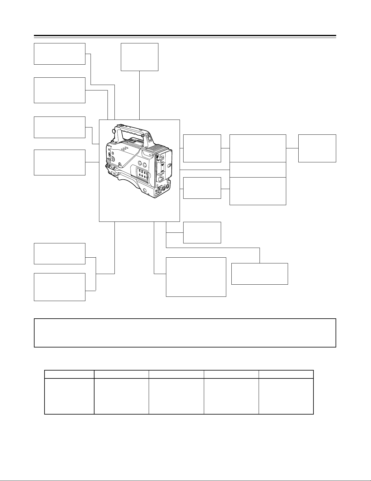
System configuration
Mic kit:
AJ-MC700
Wireless mic
receiver:
WX-RJ700
Mic holder:
AJ-MH700
Lens (bayonet type):
FUJINON/CANON
Rain cover:
SHAN-RC700
Soft carrying case:
AJ-SC900
Battery case:
AU-M402H
Battery
case/holder
AC adapter:
AJ-B75
Cassette tapes:
AY-DV124MQ
AY-DV124PQ
AY-DV186MQ
AY-DV186PQ
AY-DV276MQ
Cleaning tape:
AY-DVCL
Battery
chargers:
AG-B425
AJ-B450
Panasonic batteries:
AU-BP402
AJ-BP490
Anton Bauer batteries
Sony batteries:
BP-90
BP-L60/L90
NP-1B
1/5˝ viewfinder:
AJ-VF10
AJ-VF15
Digital Video Camera Recorder
AG-DVC200
<Note> Checking the lens shading compensation
This unit comes with a function which provides shading compensation for the lens. Check that the compensation is optimum for the type
of lens used. For further details, refer to “Lens adjustments and checks” (page 15).
Lens classification
Lens type
A B
S18 k 6.7BERM4
S18 k 6.7BRM4
S19 k 6.5BERM4
S19 k 6.5BRM4
YH18 k 6.7IRS
YH12 k 4.8IRS
YH18 k 6.7KRS
YH14 k 7.3KRS
YH12 k 4.8KRS
S14 k 7.5BRM4
S17 k 6.6BRM4
C
S14 k 7.3BRM
(For AG-DVC200D)
USER
Lens other than A, B or C
Lens shading compensation data selection
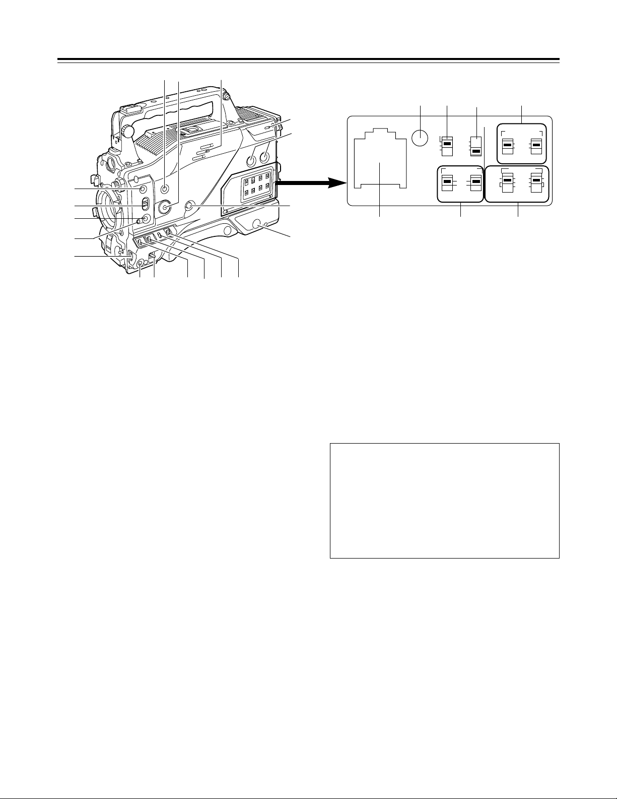
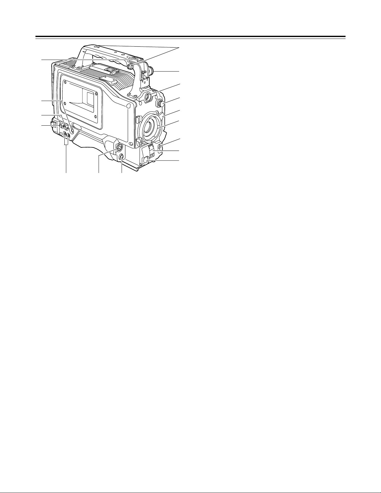
Parts and their functions
1
POWER switch
This switch turns the power ON and OFF.
4
OUTPUT/AUTO KNEE selector switch
This switch selects the video signals which are to be output from
the camera unit to the VTR unit, viewfinder and/or video
monitor.
CAM, AUTO KNEE ON:
The images shot by the camera are output. The AUTO
KNEE circuit operates.
CAM, AUTO KNEE OFF:
The images shot by the camera are output. The MANUAL
KNEE circuit operates.
BARS:
Color bar signals are output. The AUTO KNEE circuit does
not operate.
1B
<:
@
;
9
A
?
=
>
8
6
7
5432
3
GAIN selector switch
When the camera screen is dark, turn this switch to a position
which will increase the gain and brighten the screen.
The gain for each item can be selected on-screen. For further
details, refer to the table for <SW MODE> in the section on the
setting menu screens (page 33).
L: The switch is normally set to this position. The gain at this
position was set to 0 dB at the factory prior to shipment.
M:The gain of the camera’s video amplifier is increased. The
gain at this position was set to 9 dB at the factory prior to
shipment.
H:The gain of the camera’s video amplifier is increased even
more. The gain at this position was set to 18 dB at the
factory prior to shipment.
2
VTR STBY/SAVE (tape protection) switch
This switches the power supply mode when the VTR is set to
the rec pause mode in which recording is temporarily
suspended.
STBY:In this mode, recording starts immediately by pressing
the VTR START button.
SAVE:This is the tape protection mode. The tape drum is
stopped in the half-loading status. Less power is
consumed at this position than at the STBY position so
that the battery will supply power to the unit for a longer
period of time.
Compared with the STBY position, more time is taken to
start recording after the VTR START button is pressed.
When the switch is set to the SAVE position, the VTR
SAVE lamp inside the viewfinder lights up.
<Note>
When the PAUSE TIMER time has elapsed in the STBY mode,
the unit is automatically set to the SAVE mode. For further
details, refer to the table for <VTR OPTION> in the section on
the sub-menu screens (page 34).
AUTO KNEE function
When shooting with the level set to people or scenes against a
high-brightness background, the background will be whitened
out, and the buildings and scene in the background will be
blurred. If the AUTO KNEE function is activated at times like
this, the background will be reproduced clearly. This function
is effective for shooting in the following situations:
≥When shooting people in the shade under a clear sky
≥When simultaneously shooting people in a car or indoors
and the outside scenery through a window
≥When shooting scenes with a strong contrast
6
RESET
COUNTER AUDIO SELECT
AUDIO IN
AUTO
MIC
FRONT
REAR
MIC
LINE
MAN
TCG
TC
UB
ON
OFF
CH1 CH1 CH2
CH1
CH2
CH2
F-RUN
SET
R-RUN
MIC POWER
G
DC E F
HI
5
WHITE BAL (white balance memory
selector) switch
A or B:When the AUTO W/B (white/black) BAL switch on the
front panel is operated to adjust the automatic white
balance, the adjusted value is automatically stored in A
or B.
PRST: The color temperature is set to 3200K in the preset
mode. The AUTO W/B BAL switch does not work at this
position.
<Reference>
The automatic tracking white balance mode (ATW) can be set to
A, B or PRST. For further details, refer to the table for <SW
MODE> in the section on the sub-menu screens (page 33).

7
Parts and their functions
B
MENU button
This is used to switch the menu ON and OFF.
A
JOG dial button
This is used to select the menu items and perform settings when
the MENU button B is at the ON position. When the synchro
scanning mode has been selected for the shutter speed, the
shutter speed can be easily adjusted more finely.
?
FULL AUTO button
This is pressed when there is no time to check the camera unit’s
settings. The lens iris and white balance will be automatically
adjusted.
@
FULL AUTO lamp
This lights up when FULL AUTO shooting is being performed.
>
AUTO IRIS MODE selector switch
This is used to select the position that matches the shooting
conditions when shooting by automatically adjusting the lens
iris.
BACK.L : When making a back-lit subject brighter for shooting
STD :For normal shooting
SPOT.L : For shooting a spot-lit subject
=
QUICK FOCUS button
This supports the focusing of the subject. When it is pressed,
the lens iris is opened for about 10 seconds. It makes the depth
of field shallower and facilitates focusing.
<
MODE CHECK button
This enables the setting modes of the camera’s control switches
to be checked in the viewfinder.
;
SCENE FILE dial
This enables the camera settings that match the shooting
conditions to be selected. For further details, refer to “How to
use file select” (page 24).
:
SPEAKER
The sound can be monitored through this speaker.
When an earphone is connected to the PHONE jack, the sound
of the speaker will be automatically cut off.
What can be monitored is the mixed sound of CH1 and CH2.
7
MONITOR (volume) control
This is used to adjust the volume of the monitor speaker or
earphone.
8
AUDIO LEVEL CH1, CH2 (audio channel 1,
2 recording level) controls
These are used to adjust the CH1 and CH2 recording levels
while monitoring the level meter inside the viewfinder.
9
POWER/WARNING lamp
This lamp lights up green when the power is turned on, and it
flashes in green during interval recording. When a warning is
given, it lights up red or flashes in red to alert the user. For
further details, refer to “Warning system” (page 38).
6
BREAKER switch
If an excessively high current flows inside the unit due to some
problem or other, the circuit breaker is tripped and the power is
automatically turned off to protect the unit.
Push this button in after conducting an inspection or repairs
inside the unit. If there are no problems, the power will come
back on.
D
COUNTER selector switch
This is used to switch the counter display.
COUNTER: A relative numerical value is displayed by the
counter. However, when the tape recording
includes discontinuous parts, the counter reading
may also lack continuity.
TC : The time code is displayed.
UB :The user’s bit is displayed.
E
TCG selector switch
This sets the time code operation mode to FREE RUN, REC
RUN or SET. For further details, refer to “Setting the time data”
(page 22).
F
AUDIO SELECT CH1, CH2 (audio channel 1,
2 auto/manual level adjustment selector)
switches
8
Parts and their functions
4
1
2
3
=
@
5
6
>
789
:
?
;
<
4
AUTO W/B (white/black) BAL switch
AWB:The white balance is automatically adjusted. When the
AWB memory selector switch on the side panel is set to A
or B and then the AUTO W/B BAL switch is operated, the
adjustment value is recorded in the memory. Bear in
mind that the switch does not work when it is set to the
ATW or PRST position.
ABB: The black balance is automatically adjusted.
1
CC/ND filter selector knob
This is used to select the filter to match the subject brightness.
1 :3200K
2 :5600K+1/8ND
3 :5600K
4 :5600K+1/64ND
5
SHUTTER switch
This is the ON/OFF selector switch of the electronic shutter.
OFF: The electronic shutter does not operate.
ON : The electronic shutter operates.
SEL: This is used when the electronic shutter speed is to be
changed. The switch is a non-locking type. The shutter
speed changes each time it is operated. For further
details, refer to “Electronic shutter settings” (page 21).
6
VTR START/STOP button
This starts or stops the video recording.
3
Lens mount (bayonet type)
The lens is attached to this mount.
7
LENS jack (12-pin)
The connecting cord of the lens is connected to this jack. For
further details on the lenses that can be used, refer to the
operating instructions of the lenses concerned.
8
MIC IN (mic input) jack (XLR, 3-pin)
The accessory microphone is connected to this jack. The power
for the microphone is supplied from this jack.
2
Lens lever
This lever is tightened to secure the lens after the lens has been
attached to the lens mount.
:
GENLOCK IN connector (BNC)
Supply the sync signal (black burst signal) to this connector
when gen-locking the camera pictures (CAM OUT jack) of the
unit.
9
AUDIO OUT jacks (pin jacks)
An audio component is connected to these jacks. The sound for
channel 1 and channel 2 is output separately.
>
Viewfinder stopper screw
This screw is used to secure the viewfinder.
?
Light shoe
The video light or other such device is attached here.
@
Shoulder belt fittings
The shoulder belt (optional accessory) is attached here.
<
S-VIDEO OUT jack (Y/C jack)
When pictures are to be recorded with a backup VTR connected
to the S-VIDEO OUT jack, bear in mind that the unit’s playback
pictures will be recorded onto the backup VTR if any operation
(such as REC CHECK) that performs VTR playback is
executed.
;
CAM OUT jack
This is the dedicated output jack for the camera’s pictures.
=
Viewfinder connector
The viewfinder plug is connected to this connector.
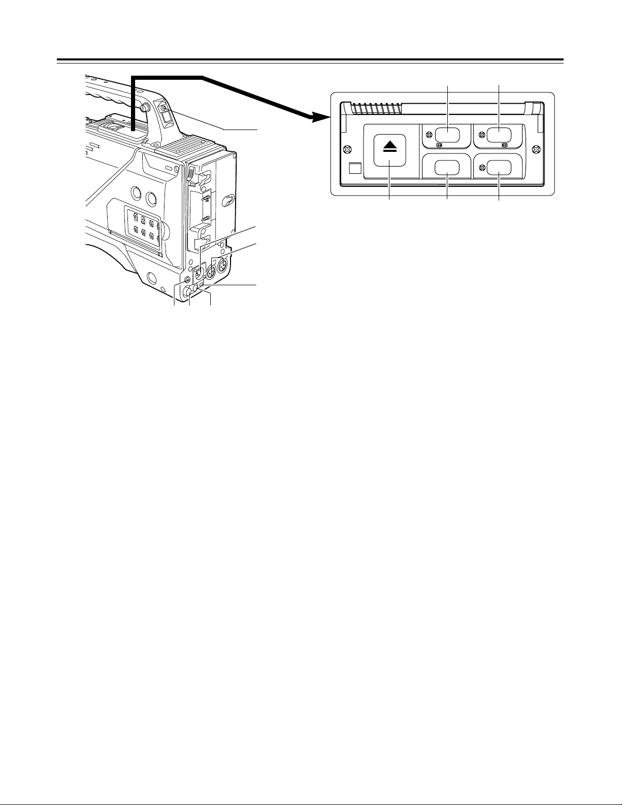
9
Parts and their functions
2
External DC input socket
This is the input socket of the external power supply (DC power
supply). When an AC adapter is connected here, power is
automatically supplied from the external source.
3
AUDIO IN CH1, CH2 (audio input channel 1,
2) jacks (XLR, 3-pin)
An external microphone or line input signals are connected to
these jacks.
5
DC OUT (DC power supply) output socket
This normally serves as the DC 12 V output socket. A current of
approximately 1 A can be taken out.
When the HDD adapter scheduled to be developed in the future
is connected here, it will be possible to supply a 7 V voltage.
6
VIDEO OUT jack (BNC)
This is the composite video jack for a monitor.
<Note>
When pictures are to be recorded with a backup VTR connected
to the VIDEO OUT jack, bear in mind that the unit’s playback
pictures will be recorded onto the backup VTR if any operation
(such as REC CHECK) that performs VTR playback is
executed. Use the exclusive camera output jack for backup
recording.
7
PHONES (earphones) jack (mini jack)
The earphones (stereo) for monitoring sound are plugged in
here. When the earphones are connected, no sound will be
output from the speaker.
1
TALLY lamp
This lights up when the unit is set to the recording mode. It
flashes when it is being transferred to the recording mode.
4
DV I/F connector (complying with IEEE
1394 standard)
A digital video component or computer equipped with a DV
connector is connected to this connector using a DV cable
(optional accessory). For further details, refer to “Using the unit
with external components” (page 29).
1
2
3
4
67
5
9
8
:;
8
REW (rewind)/FF (fast forward) buttons/
lamps
≥When one of these buttons is pressed in the stop mode, the
high-speed playback (rewind or fast forward) mode is
established, and the corresponding lamp lights.
≥When one of these button is pressed in the playback mode,
the 4a speed playback (rewind or fast forward) mode is
established, and when the same button is pressed again, the
8a speed playback (rewind or fast forward) mode is
established.
Each time the button is then pressed, the mode is switched
between 4a speed playback and 8a speed playback.
≥When one of these buttons is pressed in the STILL or REC
PAUSE mode, the 1a speed playback (rewind or fast forward)
is established while the button is held down. When the button
is released, the unit returns to the previous mode (STILL or
REC PAUSE).
The variable speed playback mode is released by pressing the
STOP button, PLAY/PAUSE button or EJECT button.
9
STOP button
The tape stops traveling when this button is pressed. However,
the button cannot be operated during recording. To stop
recording, first set the unit to the REC/PAUSE mode, and then
press the STOP button.
:
PLAY/PAUSE button/lamp
Playback commences when this button is pressed, and the lamp
lights. When it is pressed again, the STILL mode is established,
and the lamp flashes.
When it is pressed once more, the playback mode is restored.
;
EJECT button
When this button is pressed, the cassette holder rises, and the
cassette tape can be inserted or removed. This button cannot
be operated while the unit is recording, in which case first set
the unit to the REC/PAUSE mode, and then press the EJECT
button.
8
6
/
REW FF
EJECT
STOP PLAY/PAUSE
ª
5
/
1/;
11
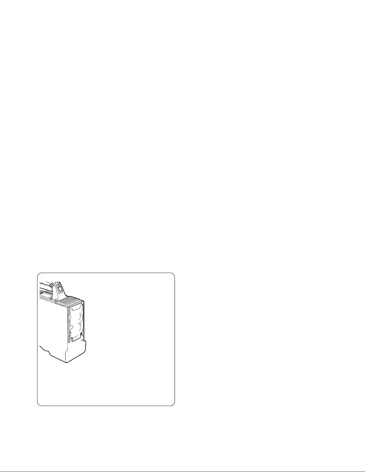
Preparation
Using a battery pack made by Anton Bauer
1
Attach the battery pack made by Anton
Bauer.
2
Insert the battery pack and slide it in the
direction of the arrow.
Power output connector for lighting
Battery pack made by Anton Bauer
Before use, charge the battery pack using the exclusive battery
charger made by Anton Bauer.
For the charging time and other details, refer to the operating
instructions of the battery charger used.
Lighting control switch
<Reference>
A battery holder made by Anton Bauer is equipped with a power
output connector for the lighting and a lighting control switch to
enable a light to be easily attached. For details on the lighting
systems available, contact Anton Bauer.
3
Set the battery type.
Select the battery type using <BATTERY> on the sub-menu
screen.
Example: Select “NiCd13” if the TRIMPAC13 is to be used;
select “NiCd14” if the TRIMPAC14 is to be used.
(See page 34)
3
Set the battery type.
Select the battery type using <BATTERY> on the sub-menu
screen.
Select “NiCd12” if the NP-1B is to be used. (See page 34)
<Reference>
To remove the battery pack, slide it in the opposite direction to the
one in which it was attached while keeping the release lever on the
battery holder pulled down all the way.
Release lever
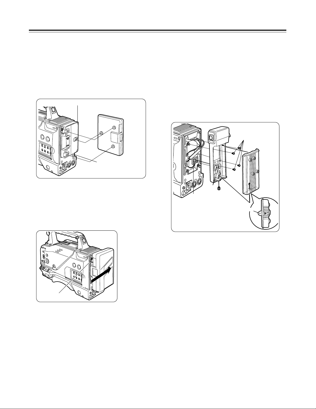
2
Using the NP-1B battery pack made by Sony
Before use, charge the battery pack using the exclusive battery
charger made by Sony.
For the charging time and other details, refer to the operating
instructions of the battery charger used.
Refer to step 1 on page 10.
1
Remove the battery holder.
2
Attach the battery made by Sony to the
unit.
Screw provided
with mounting
connector for
NP-1B
Mounting
connector for
NP-1B
Cover
2
1
3
4
5
Battery case
Hole
First, remove the battery holder cover.
1 Attach the mounting connector for the NP-1B.
2 Use the mounting screws to mount the battery case.
3 Tighten the screw for the power supply contact.
4 Insert the top of the cover in the direction of the arrow.
5 Align the hole in the bottom of the cover (metal part) with the
hole in the bottom of the battery case, and attach using the
screw provided with mounting connector for NP-1B.
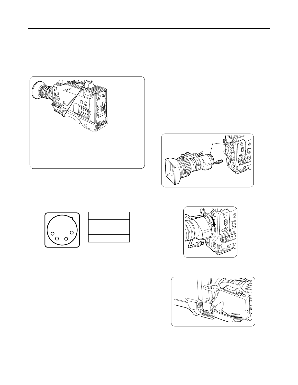
12
Attaching the lens
1
Raise the lens lever, and remove the
mount cap.
4
Push the cable into the cable clamp, and
connect it to the LENS jack.
Mark
3
Pull down the lens lever to secure the
lens.
LENS jack
<Notes>
≥For details on how to handle the lens, refer to the operating
instructions of the lens.
≥While the lens is removed, attach the mount cap to protect the
unit.
Preparation
Using an AC power supply (with the AJ-B75 AC adapter)
1
Connect the unit’s external DC input
socket with the DC OUT socket on the AJB75 AC adapter.
2
Turn on the AC adapter’s power.
5
Proceed with the flange back adjustment
for the lens.
3
Set the unit’s POWER switch to ON.
When an AC adapter other than the AJ-B75 is to be used,
check the pin signals of the external DC input socket.
<Notes>
≥When both a battery pack and an AC adapter have been
connected, the power supplied from the AC adapter takes priority.
It is also possible to attach/remove a battery while the AC adapter
is being used.
≥When an AC adapter is to be used, the unit’s POWER switch must
be set to ON only after the AC adapter’s power has been turned
on. If the power is switched on in the reverse sequence, the AC
adapter’s output voltage will rise slowly, possibly causing the unit
to malfunction.
Pin No Signal
1 GND
2, 3 –
4 +12 V
1
2
3
4
External DC input socket
13
Preparation
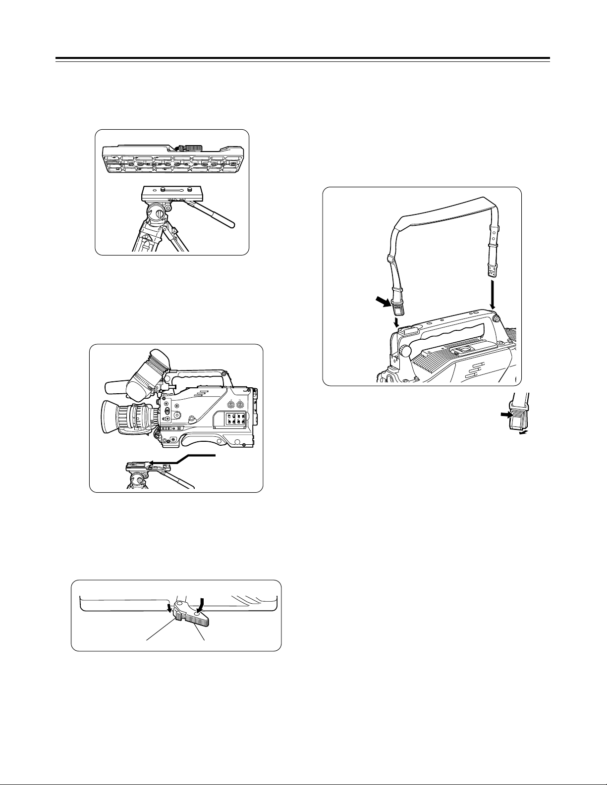
Tripod attachment
Mounting the unit on a tripod
1
Mount the tripod attachment on the tripod.
Use the tripod attachment to mount the unit on a tripod.
For details on the attachment and adjustments of the viewfinder and
microphone, refer to the operating instructions of the viewfinder.
<Note>
Take account of the center of gravity of the unit and that of the
tripod attachment when selecting the attachment hole. Check that
the diameter of the hole selected matches the diameter of the tripod
head screw.
2
Mount the unit on the tripod attachment.
Slide the unit along the groove toward the front until it clicks into
place.
Tripod head
Tripod attachment
Detaching the unit from the tripod attachment
Red lever
While pushing down the red lever, move the black lever in the
direction of the arrow and slide the unit toward the back to remove
it.
<Note>
If the pin of the tripod attachment fails to return to its original
position after the unit has been detached, again move the black
lever in the direction of the arrow while pushing down the red lever,
and return the pin to its original position. Bear in mind that the unit
cannot be attached if the pin remains in the center.
Black lever
Attaching the shoulder belt (optional accessory)
Attaching the viewfinder and microphone
Shoulder belt
The tab opens
when it is
pressed.
<Note>
Check that the shoulder belt is attached securely.
To disengage the shoulder belt,
open the tabs of the attachment
parts, and disengage.
The tab opens
when it is
pressed.

14
Preparation
Setting the camera ID
The camera ID is set on the <CAMERA ID> screen. Up to 12
alphanumerics, symbols and spaces can be used.
<Note>
The camera ID does not appear while the setting menu is displayed
even when color bar signals are output.
<Note>
The camera ID input above will be recorded at the same time as the
color bar signals.
1
Proceed with the sub-menu operation
(page 30), and open the <CAMERA ID>
screen.
4
Keep turning the JOG dial button until the
character to be set appears.
6
Turn the JOG dial button to move the
arrow (cursor) to the next position (on the
right), and repeat steps 3, 4 and 5 to enter
the remaining characters.
5
Press the JOG dial button to enter the
character.
7
Press the MENU button to end the menu
operation.
#3
< CAMERA ID >
CAMERA ID:ID
ID:
¢¢¢¢¢¢¢¢¢¢¢¢
2
Turn the JOG dial button to move the
arrow (cursor) to the ID item.
3
When the JOG dial button is pressed, the
arrow (cursor) flashes to signal that the
input mode has been established.
3
< CAMERA ID >
CAMERA ID:ID
v
#
ID:
¢¢¢¢¢¢¢¢¢¢¢¢
When the button is turned, the character display is switched in
the following sequence:
Space: ∏
7
Letters of the alphabet: A through Z
7
Numbers: 0 through 9
7
Symbols: ', >, <, /, -
The setting menu is cleared, and the unit’s current status is
displayed.
To change the ; back to >, press the JOG dial button when
the ; is above the colon (:).
Setting the date and time
1
Proceed with the sub-menu operation
(page 37) to open the <TIME/DATE> screen.
#3
< TIME/DATE >
YEAR :01
MONTH :01
DAY :01
HOUR :00
MINUTE :00
TIME/DATE SET:READY
2
Turn the JOG dial button to select the item
to be changed, and press the JOG dial
button.
3
< TIME/DATE >
YEAR :01
MONTH :01
DAY :01
HOUR :00
#
MINUTE :00
TIME/DATE SET:READY
4
When the setting is completed, turn the
JOG dial button to select TIME/DATE SET,
and press the button.
3
< TIME/DATE >
YEAR :01
MONTH :01
DAY :01
HOUR :00
MINUTE :00
#
TIME/DATE SET:OK
3
Turn the JOG dial button to change the
setting, and then press the button to enter it.
The READY display changes from ACTIVE to OK, and the
clock function starts operating.
The setting menu is cleared, and the unit’s current status is
displayed.
5
Press the MENU button to end the menu
operation.
<Note>
≥The seconds cannot be set. The time always starts from zero
seconds.
≥At normal temperature with the power off, the clock will have an
accuracy of ±30 seconds/month. When accurate time is
necessary, check the time with the power on and reset to the
correct time.
 Loading...