

Page 1
www.pace.com
Page 2

Page 3
Manufactured under license from Dolby Laboratories.
Dolby and the double-D symbol are trademarks of Dolby Laboratories.
This product incorporates copyright protection technology that is protected by
U.S. patents and other intellectual property rights. Use of this copyright protection
technology must be authorized by Macrovision, and is intended for home and
other limited pay-per-view uses only unless otherwise authorized by Macrovision.
Reverse engineering or disassembly is prohibited.
HDMI, the HDMI Logo and High-Definition Multimedia Interface are trademarks
or registered trademarks of HDMI Licensing LLC.
Other trademarks listed herein are the proper ty of their respective owners.
© 2008 Pace plc.
All rights reserved.
Pace and are trademarks and/or registered trademarks of Pace plc
This manual describes some on-screen displays such as menus.
These may change in the future, if the set-top’s software is
updated over the cable. However, the way that you use the
menus will remain similar to the way described in this manual.
CONTENTS
SAFETY INFORMATION .............................................................................................2
REAR PANEL ...................................................................................................................8
CONNECTING THE EQUIPMENT ........................................................................ 10
Connecting your TV to the AC power supply ................................................ 14
Connecting the power cord to your set-top .................................................14
Connecting equipment to the wall AC outlets ...............................................14
OPERATING YOUR SET-TOP ................................................................................... 15
Turning your set-top on and off .........................................................................15
Using your remote control ................................................................................. 16
Lightning storms .................................................................................................... 16
Using the front-panel buttons ............................................................................ 17
Using your set-top’s DVR functions ..................................................................18
Using an external hard disk ................................................................................ 19
Using RF Bypass ..................................................................................................... 20
MAKING USER SETTINGS ....................................................................................... 21
About User Settings ............................................................................................. 21
About the TV Aspect Ratio ................................................................................. 22
About TV Display Capability (resolution settings) ......................................... 23
Setting Auto Pillarbox ...........................................................................................26
Making Closed Captions Settings ...................................................................... 28
Setting Front Panel Brightness ........................................................................... 29
Setting Hard Disk Sleep Mode ........................................................................... 30
Changing HDMI Settings .....................................................................................31
Removing the User Settings menus .................................................................. 31
Restoring the factory default settings ..............................................................32
USING ZOOM ............................................................................................................. 34
USING THE SETUP MENUS ..................................................................................... 35
SOLVING PROBLEMS ................................................................................................ 36
TERMS AND CONDITIONS FOR USE OF SOFTWARE (“TERMS”) ...........40
1
Page 4
SAFETY INFORMATION
RISK OF ELECTRIC SHOCK
DO NOT OPEN
CAUTION
RISQUE DE CH OC ELECTRIQUE
NE PAS OUVRIR
ATTENTION
This digital set-top has been manufactured and tested with your
safety in mind. However, improper use can result in potential
electric shock or fire hazards. To avoid defeating the safeguards that
have been built into your set-top, please observe the precautions
discussed in this document.
Warnings on your set-top
The lightning flash with arrowhead symbol, within a
triangle, is intended to alert you to the presence of
uninsulated “dangerous” voltages within your set-top’s
enclosure that may be of sufficient magnitude to
constitute a risk of electric shock to persons.
The exclamation point within a triangle is intended to
alert you to the presence of important instructions in
the literature accompanying your set-top.
Other warnings
To reduce the risk of electric shock, do not remove the cover of
your set-top. There are no user-serviceable parts inside it.
Do not perform any servicing unless you are qualified to do so.
Refer all servicing to qualified ser vice personnel. Servicing the set-
2
top yourself will invalidate the warranty.
To reduce the risk of fire or electric shock, do not expose this settop to rain or moisture.
On the rear panel of your set-top there is a tamper-evident label
that states ‘Warranty void if broken or removed’.
To avoid possible damage to the internal hard disk, do not pick up
or move your set-top while it is connected to the wall AC outlet. If
you want to move your set-top, first stop any recording, then turn off
your set-top and wait 60 seconds before disconnecting it. You should
handle your set-top carefully, as any damage you cause to the internal
hard disk (or any other component) will invalidate your warranty.
Installation
The installation of your set-top should be carried out by a qualified
installer and should conform to local codes.
Note to the installer
This reminder is provided to call the attention of the cable-TV-system
installer to Section 820 of the National Electrical Code (USA), which
provides guidelines for proper grounding and, in particular, specifies that
the cable ground shall be connected to the grounding system of the
building, as close to the point of cable entry as is practical.
Service address:
Pace Americas Inc.
3701 FAU Boulevard, Suite 200, Boca Raton
Florida 33431 U.S.A.
Page 5

IMPORTANT SAFETY INSTRUCTIONS
Before you install or use the apparatus, you must read
and understand these Important Safety Instructions.
At all times when using the apparatus you must follow
these Important Safety Instructions to reduce the risk of
fire, electrical shock and injury to persons.
1. Read these instructions.
2. Keep these instructions.
3. Heed all warnings.
4. Follow all instructions.
5. Do not use this apparatus near water.
6. Clean only with dry cloth.
7. Do not block any ventilation openings. Install in accordance
with the manufacturer’s instructions.
8. Do not install near any heat sources such as radiators, heat
registers, stoves, or other apparatus (including amplifiers) that
produce heat.
9. Do not defeat the safety purpose of the polarized or groundingtype plug. A polarized plug has two blades with one wider than
the other. A grounding type plug has two blades and a third
grounding prong. The wide blade or the third prong are provided
for your safety. If the provided plug does not fit into the outlet,
consult an electrician for replacement of the obsolete outlet.
10. Protect the power cord from being walked on or pinched
particularly at plugs, convenience receptacles, and the point
where they exit from the apparatus.
11. Only use attachments/accessories specified by the
manufacturer.
12. Use only with the cart, stand, tripod, bracket, or table
specified by the manufacturer, or sold with the apparatus.
When a cart is used, use caution when moving the cart/
apparatus combination to avoid injury from tip-over.
13. Unplug this apparatus during lightning storms or when
unused for long periods of time.
14. Refer all servicing to qualified service personnel. Servicing is
required when the apparatus has been damaged in any way,
such as power-supply cord or plug is damaged, liquid has been
spilled or objects have fallen into the apparatus, the apparatus
has been exposed to rain or moisture, does not operate
normally, or has been dropped.
3
Page 6

SAFETY INFORMATION (cont.)
1 inch
1 inch1 inch
In addition to the Important Safety Instructions, please read the
Safety Information below.
Power sources
The model number, serial number and electrical rating of this settop are on a label on its base.
You must operate your set-top only from the type of power
source indicated on the marking label. If you are not sure of the
type of power supply to your home, consult your dealer or local
power company. If you move your set-top between locations at
different temperatures, allow it to reach room temperature before
you apply power to it.
Water and moisture
Do not expose your set-top to dripping or splashing and ensure
that no objects filled with liquids, such as vases, are placed on your
set-top. See also item 5 in the Important Safety Instructions.
Lightning
For added protection for your set-top during a lightning storm,
or when it is left unattended and unused for long periods of time,
disconnect the cable system from your set-top. See also item 13 in
the Important Safety Instructions.
Placement and mounting
Do not place your set-top on an unstable or uneven surface.
Your set-top may fall, causing serious injury to a child or adult and
serious damage to your set-top. If you mount your set-top, for
4
example to a wall or ceiling, follow the manufacturer’s instructions
and use a mounting accessory recommended by the manufacturer.
See also item 12 in the Important Safety Instructions.
Ventilation
Slots and openings in the casing of your set-top are provided for
ventilation, to ensure reliable operation of your set-top and to
protect it from overheating.
• Neverblocktheventilation
openings by placing your
set-top on a bed, sofa, rug or
other similar surface.
• Nevercovertheventilation
openings with items such as
newspapers, table-cloths or
curtains.
• Donotplaceyourset-top
in a built-in installation such
as a bookcase or rack unless
proper ventilation is provided
or you have adhered to the
manufacturer’s instructions.
• Itisrecommendedthatyoumaintainaminimumdistanceof
1 inch around your set-top for sufficient ventilation.
See also item 7 in the Important Safety Instructions.
Page 7

SAFETY INFORMATION (cont.)
Entry of objects and liquids
Never push objects of any kind into your set-top through openings
as they may touch dangerous voltage points or short-out par ts that
could result in fire or electric shock. Never spill liquid of any kind
on your set-top.
Transporting
Move the combination of set-top and cart with care. Quick stops,
excessive force and uneven surfaces may cause the combination
of set-top and cart to overturn. See also item 12 in the Important
Safety Instructions.
Risk of fire or scorching
Never place naked flame sources, such as lighted candles, on or
adjacent to your set-top.
Ambient temperature
The operating temperature range of your set-top is 32-104°F. If the
ambient temperature around your set-top falls outside this range,
you must correct this in order for your set-top to work correctly
and safely. For example, if the temperature is too high, switch on
the air conditioning.
Overloading
Do not overload wall outlets, extension cords or other power
outlets as this can result in a risk of fire or electric shock.
Replacement parts
When replacement parts are required, be sure that the
service technician has used replacement parts specified by the
manufacturer or that have the same characteristics as the original
part. Unauthorized substitutions may result in fire, electric shock or
other hazards. See also item 14 in the Important Safety Instructions.
Safety check
Upon completion of any servicing or repairs to your set-top, ask
the service technician to perform safety checks to determine that
your set-top is in its proper operating condition. See also item 14
in the Important Safety Instructions.
SAVE THIS INFORMATION FOR FUTURE REFERENCE
5
Page 8

SAFETY INFORMATION (cont.)
Safety aspects of connections
Full details of the rear panel are on page 8.
Connecting
Do not connect your set-top (or any other equipment such as a TV
or VCR) to the power supply until you have properly connected all
the other cables.
Your set-top operates with a 120 V AC, 60 Hz power supply.
Do not connect your set-top to any supply other than this.
This set-top is equipped with a two-wire power cord, with a
polarized plug at one end. The other end of the cord is fitted with a
polarized connector, which is shaped such that it can be fitted only
one way into the power input jack of your set-top. Connect this
end first, before inserting the polarized plug into the wall socketoutlet.
Disconnecting
Disconnect your set-top from the power supply before you
disconnect any other equipment from its rear panel.
The only way to disconnect your set-top from the power supply
is to remove the power cord from the wall socket-outlet. Your
set-top must therefore be installed near to the wall socket-outlet,
which should be easily accessible.
The POWER OUTLET plug is designed only for connection to the AC
power cord for a TV. The maximum power it can supply is 500 watts.
Do not connect any equipment that uses more than 500 watts, or
any non-TV equipment such as a toaster or hair dryer.
The CABLE IN connector is designed for
connection to a cable network only.
You must not connect any other equipment,
such as a VCR, to this input.
POWER INPUT
The model number, serial
number and electrical
rating of this set-top are
on a label on its base.
6
Page 9
SAFETY INFORMATION (cont.)
Epilepsy and on-screen images
Certain people are susceptible to epileptic seizures or losing
consciousness when faced with certain types of flashing lights in
our daily environment.
These people are exposed to the risk of seizures if they watch
certain television images or if they view certain images while they
are browsing the Web. These phenomena may appear even when
the subject has no previous history of this problem or has never
suffered an epileptic seizure.
If you, or a member of your family, has already suffered symptoms
linked to epilepsy (seizure or loss of consciousness) in the presence
of stimulation by light, please consult your doctor before using this
product.
If you or any person using the equipment experiences dizziness,
involuntary movements or convulsion, please immediately stop
viewing and consult a doctor.
When you are browsing the Web or playing a Web-based game,
take the following precautions.
• Usetheequipmentinawell-litroom,andturndownthe
brightness of your television screen.
• Sitatareasonabledistancefromyourtelevisionscreen.
• Takeabreakfortenminuteseveryhour.
You should avoid using the Web if you are tired or have lost some sleep.
Regulatory information
CAUTION: Do not attempt to modify your set-top without
written authorization from the manufacturer. Unauthorized
modification could void your authority to operate your set-top.
NOTE
Your set-top has been tested and found to comply with the limits for
a Class B digital device, pursuant to Part 15 of the FCC Rules. These
limits are designed to provide reasonable protection against harmful
interference in a residential installation. Your set-top generates, uses
and can radiate radio-frequency energy and, if not installed and used
in accordance with the instructions, may cause harmful interference to
radio communications.
However, there is no guarantee that interference will not occur in a
particular installation. If your set-top does cause harmful interference
to radio or television reception, which can be determined by turning
your set-top off and on, you are encouraged to try to correct the
interference by one or more of the following measures.
•Reorientorrelocatethereceivingantenna.
•Increasetheseparationbetweenyourset-topandthereceiver.
•Connectyourset-toptoanoutletonacircuitdifferentfromthatto
which the receiver is connected.
•Consultyourdealeroranexperiencedradio/TVtechnicianforhelp.
7
Page 10
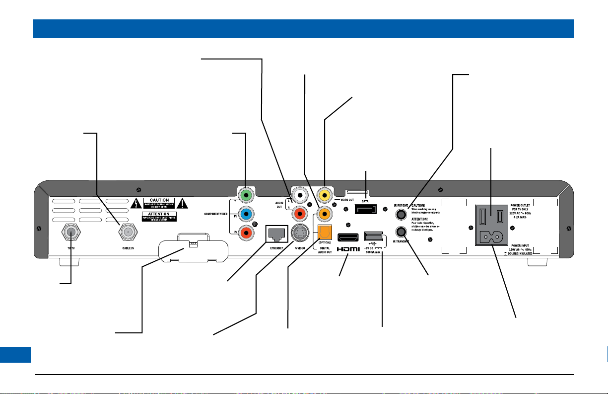
REAR PANEL
CABLE IN
From cable
service-provider
TO TV
RF output to the
TV or VCR
TV PASS MODULE
Connector for a TV pass®
module (for installers’ use only)
8
AUDIO OUT
Audio outputs
(stereo, L and R)
COMPONENT VIDEO
Component video output for
analog HDTV
ETHERNET
To connect to
optional PC
S-VIDEO
S-video output
DIGITAL AUDIO OUT
Electrical S/PDIF audio output
TM
HDMI
Video and audio
output for digital
HDTV
OPTICAL AUDIO OUT
Optical S/PDIF audio output
VIDEO OUT
Composite video output
SATA
For connection to an
optional external
hard disk
Universal Serial Bus
(USB) port
To connect USB devices
IR RECEIVE
Infra-red input from
a remote “eye”
POWER OUTLET
(500 W max.)
IR TRANSMIT
Infra-red output to control
a VCR (future use)
POWER INPUT
(Make this
connection
last of all)
Page 11
REAR PANEL (cont.)
CABLE IN Connect the cable service here.
TO TV ConnecttotheRF/antennainputonyourTVor
VCR (optional).
VIDEO OUT Connect to the composite video input on your
VCR (or a standard TV).
AUDIO OUT Connect to the L and R audio inputs on your
stereo TV, stereo VCR or optional stereo amplifier.
®
TV PASS MODULE Connect a TV pass
COMPONENT
VIDEO
If your HDTV does not have an HDMI
below), connect your HDTV here.
module, if required.
TM
(see
S-VIDEO Connect to the S-video input (if present) on your
VCR or TV.
IR RECEIVE Connect to an optional remote “eye”.
IR TRANSMIT Connect to an optional VCR controller (future use).
USB
(Universal Serial
Connect to compatible optional equipment that
supports a USB 2.0 interface.
Bus)
TM
HDMI
(High Definition
Multimedia
Interface)
If your HDTV has an HDMITM, connect it here
for a digitalaudio/videoconnection(insteadof
using the AUDIO and 3 analog COMPONENT
VIDEO connectors).
ETHERNET Connect to an optional PC network.
SATA Connect to an optional external hard disk
(if enabled by your cable service-provider).
DIGITAL AUDIO
OUT
Connect to the electrical digital audio input on
optional digital audio equipment, such as an audio
decoder or home theater receiver.
OPTICAL AUDIO
OUT
Connect to the optical digital audio input on
optional digital audio equipment.
POWER OUTLET Connect your TV’s power cord here to provide
AC power to your TV.
POWER INPUT Connect your set-top’s power cord here.
9
Page 12
CONNECTING THE EQUIPMENT
In order for you to view programs broadcast in high-definition, your set-top must be
connected to a suitable HDTV or computer monitor. Your set-top is also compatible
with standard-definition TVs and VCRs.
Your equipment should have been connected up by your installer. However, if you
need to disconnect and re-connect your equipment, please read pages 10 to 14.
On pages 12 and 13 there are two typical connection set-ups for an HDTV, VCR,
DVD player and home theater receiver.
These set-ups make efficient use of the connectors on your set-top. However,
depending on your other equipment and the connectors on it, the person who
installed your system may have chosen to connect things up differently.
Both set-ups allow stereo recording and play-back of video tapes. You hear stereo
sound from the home theater’s loudspeakers.
Although the RF cables (shown by dashed lines in the diagrams) are not absolutely
necessary, we recommend that you connect them as a back-up and so that you can
use the RF Bypass. If you use the RF cables, you must tune your TV (and VCR) to
your set-top’s VHF output channel (3 or 4: consult your cable service-provider to find
which channel it is for your location). Consult the manuals supplied with your TV and
VCR for information on how to tune.
You can take advantage of the digital audio output from your set-top by connecting
a suitable cable between your home theater receiver and the (OPTICAL) DIGITAL
AUDIO OUT jack (as shown in the diagrams) or the DIGITAL AUDIO OUT jack.
10
WARNINGS
Do not connect your set-top (or any other
equipment such as a TV or VCR) to the AC power
supply until you have properly connected all the
other cables.
Disconnect your set-top from the AC power
supply before you disconnect any other
equipment from its rear panel.
The only way to disconnect your set-top from
the AC power supply is to remove the AC power
cord (or switch the wall socket-outlet switch, if
present, to its OFF position). Your set-top must
therefore be installed near to the AC power
socket-outlet, which should be easily accessible.
The power outlet is designed only for connection
to the AC power cord for a TV. The maximum
power it can supply is 500 watts. Do not connect
any equipment that uses more than 500 watts, or
any non-TV equipment such as a toaster or hair
dryer.
The cable input is designed for connection to a
cable network only. You must not connect any
other equipment, such as a VCR, to this input.
Any cable connected to DIGITAL AUDIO OUT
must be 75 ohm coaxial, not regular audio cable.
Page 13
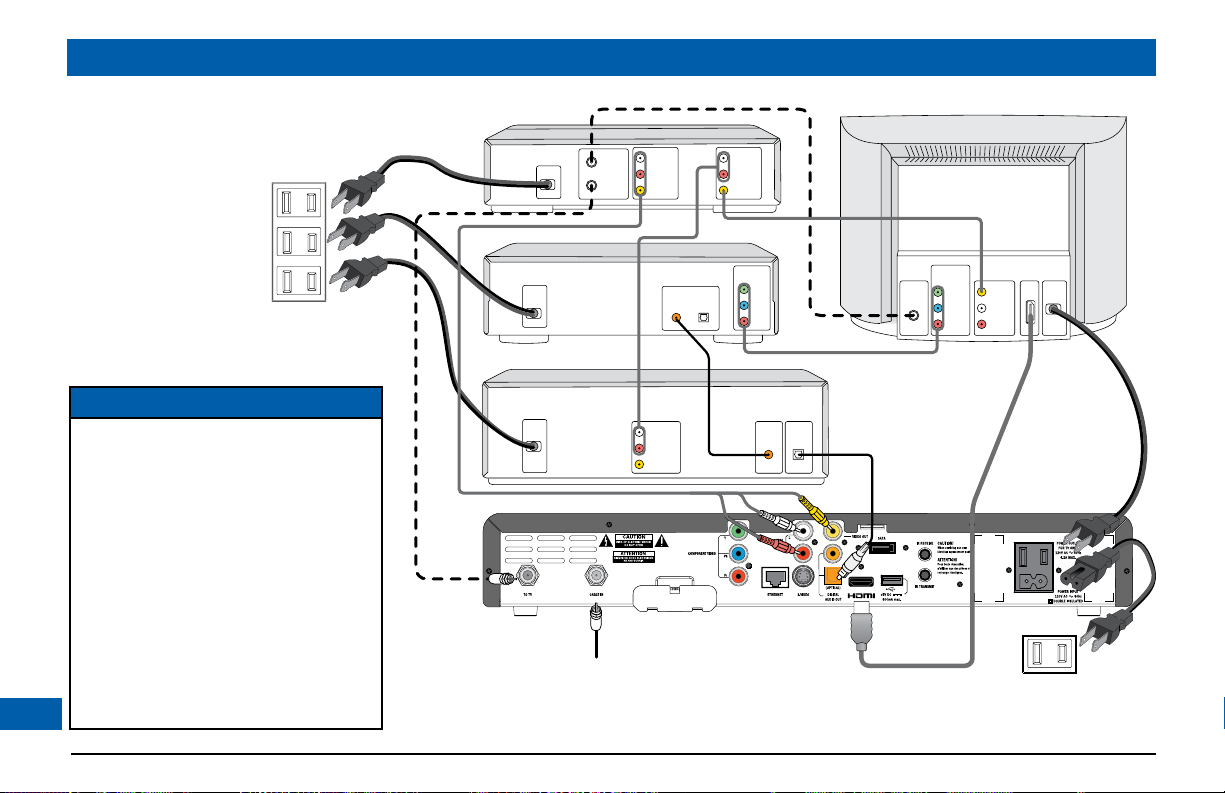
CONNECTING THE EQUIPMENT (cont.)
Set-up A - Home theater system with HDTV
(HDMI
Set-up A (see page 12) uses an HDMITM (high definition multimedia interface) connector to connect
to the HDTV. This displays the highest quality picture on the HDTV and also means there will be no
picture degradation on any copy-protected programs (provided the link remains secure – see right)
Variation
S-video provides a better TV picture than composite video, therefore, if your TV and VCR have
S-video connectors, replace the composite video connection with an S-video connection to your
VCR, then connect directly via an S-video connection from your VCR to your TV (or loop through
your home theater receiver if you prefer).
TM
connection)
Set-up B - Home theater system with HDTV
(Component video / YPbPr connection)
Set-up B (see page 13) uses a component video connection to connect to the HDTV. This displays a
high definition picture on your TV.
NOTES
How you set up your equipment may depend on your home theater receiver. For example, the optical
and digital audio inputs may be associated with particular video inputs. Please see your home theater user
information for further details.
NOTE
Copy protection via an
TM
HDMI
The HDMITM link between your
set-top and your HDTV should
be a secure link. When your
set-top is attached via an HDMI
cable to an HDCP-compliant
(High-bandwidth Digital Content
Protection) HDTV, the HDTV
and set-top negotiate a secure
link, which allows your set-top
to transmit full resolution video
(picture) to your HDTV.
Not all HDTVs support HDCP. If
your set-top is connected to an
HDTV that does not support it,
the following may be displayed:
Your HDTV does not support HDCP.
Please use the YPbPr component
connection to watch TV.
The HDMI
disabled, so no picture is transmitted
from this connector. In that case use
the component video connectors to
connect up (see Set-up B).
secure link
TM
output is then
TM
11
Page 14
CONNECTING THE EQUIPMENT (cont.)
ANTENNA/
RF IN
TV / RF
OUT
ANTENNA/
RF IN
LEFT
AUDIO IN
RIGHT
AUDIO IN
VIDEO IN
LEFT
AUDIO IN
RIGHT
AUDIO IN
VIDEO IN
POWER
LEFT
AUDIO OUT
RIGHT
AUDIO OUT
VIDEO OUT
CABLE INPUT
HDTV
VCR
DV D
LEFT
AUDIO IN
VCR IN
RIGHT
AUDIO IN
VIDEO IN
PB/CB
PR/CR
Y
COMPONENT
VIDEO OUT
HOME THEATER RECEIVER
OPTICAL
AUDIO IN
COAXIAL
AUDIO IN
DIGITAL AUDIO OUT
DIGITAL AUDIO IN
OPTICAL COAXIAL
PB/CB IN
PR/CR IN
Y IN
COMPONENT
VIDEO IN
POWER
POWER
POWER
HDMI
WA LL AC OUTLET
WA LL AC OUTLETS
Set-up A
12
NOTE
This diagram shows a video path from
the set-top to a VCR to allow recording
to the VCR. It shows a video path from
the VCR to the TV to allow playback of
videos. Video signals fed through a VCR
may be affected by copyright protection
systems, which can cause picture
distortion on your TV.
Do not therefore use a path through a
VCR to watch your set-top programs.
Use the HDMITM path or an alternate
direct video path from your set-top to
your TV. Remember to select the correct
input on your TV.
Page 15

ANTENNA/
RF IN
TV / RF
OUT
ANTENNA/
RF IN
LEFT
AUDIO IN
RIGHT
AUDIO IN
VIDEO IN
LEFT
AUDIO IN
RIGHT
AUDIO IN
VIDEO IN
POWER
LEFT
AUDIO OUT
RIGHT
AUDIO OUT
VIDEO OUT
CABLE INPUT
HDTV
VCR
DV D
LEFT
AUDIO IN
VCR IN
RIGHT
AUDIO IN
VIDEO IN
HOME THEATER RECEIVER
OPTICAL
AUDIO IN
COAXIAL
AUDIO IN
DIGITAL AUDIO OUT
DIGITAL AUDIO IN
OPTICAL COAXIAL
POWER
POWER
POWER
WA LL AC OUTLET
WA LL AC OUTLETS
PB/CB IN
PR/CR IN
Y IN
COMPONENT
VIDEO IN
S-VIDEO OUT
S-VIDEO
IN
Set-up B
CONNECTING THE EQUIPMENT (cont.)
NOTE
This diagram shows a video path from
the set-top to a VCR to allow recording
to the VCR. It shows a video path from
the VCR to the TV to allow playback of
videos. Video signals fed through a VCR
may be affected by copyright protection
systems, which can cause picture
distortion on your TV.
Do not therefore use a path through a
VCR to watch your set-top programs.
Use the component video path or an
alternate direct video path from your
set-top to your TV. Remember to select
the correct input on your TV.
13
Page 16

CONNECTING THE EQUIPMENT (cont.)
WARNINGS
Do not connect your set-top (or any other equipment such as a TV or VCR) to the AC power supply until
you have properly connected all the other cables.
Do not defeat the safety purpose of the polarized plugs on power cords. A polarized plug has two blades
with one wider than the other. This plug fits into the outlet in only one way; match the wide blade of the
plug to the wide slot of the outlet.
Connecting your TV to the AC power supply
If your TV has a rating of less than 500 W, connect the power cord from your TV into the connector
labeled “POWER OUTLET” on the rear panel of your set-top. This saves a wall outlet (although, if
your TV is rated 500 W or more, you must connect it to a wall outlet).
Connecting the power cord to your set-top
Before you connect your set-top to a wall outlet, connect the polarized socket on the power cord
into the plug labeled “POWER INPUT” on your set-top’s rear panel.
Connecting equipment to the wall AC outlets
Connect the polarized plugs on the power cords from your set-top, VCR and any other equipment
into wall AC outlets. If these outlets have switches, switch them to ON.
14
Page 17

OPERATING YOUR SET-TOP
Turning your set-top on and off
After you have connected your set-top to the wall AC outlet (and switched this outlet ON, if it has a
switch), the light around the POWER button on your set-top’s front panel should be red.
Wait for a few seconds, then press the button labeled POWER on the front panel of your set-top
to turn it on. The light around the POWER button goes green, to show that your set-top is on.
If the light around the POWER button is neither red nor green, there is a problem.
To turn your set-top on or off at any time, press the POWER button on its front panel or the
POWER button on your remote control (first making sure your remote control is set to control
your set-top).
Never turn off your set-top by simply disconnecting it from the power supply. If you need to
disconnect your set-top, first stop any recording. Then turn off your set-top by pressing the POWER
button on its front panel or on your remote control, so that the light around the POWER button
goes red. Then wait 60 seconds before disconnecting your set-top at the wall AC outlet.
Power Saving: To save power and money, and to reduce greenhouse gas emissions,
please turn off your set-top, using the POWER button, when it is not in use.
NOTES
IMPORTANT: Unless there is a lightning storm or you will be away from your home for a long time, do
not unplug your set-top at the wall AC outlet (or do not switch it off there, if the outlet has a switch).
Your set-top cannot be updated with new features, through the cable, if it is disconnected from the AC
power supply.
Depending on your set-top’s settings, if you switch your set-top off, any TV that is attached to your settop’s POWER OUTLET may also turn off. For more details, see page 35.
To turn on your set-top, press
the POWER button.
The light around the
button changes from
red to green.
Front panel display, showing
the time (see page 35)
15
Page 18

OPERATING YOUR SET-TOP (cont.)
Using your remote control
Your cable TV service-provider determines the digital channels, services and screen information that
you see on your TV when you use your set-top and its remote control.
Consult the information supplied by your cable service-provider for details on how to make the
most of the digital cable services. Also read the operating instructions that are supplied with your
remote control.
Lightning storms
Disconnect your set-top’s power cord during lightning storms. A lightning storm may affect your settop, if it is on during the storm. It may appear that it has stopped working, but you can easily restore
its operation as follows.
Unplug your set-top’s power cord at the wall AC outlet. Then plug this power cord in again at the
wall AC outlet (and, if there is a switch by this outlet, switch it to its ON position).
16
Page 19
OPERATING YOUR SET-TOP (cont.)
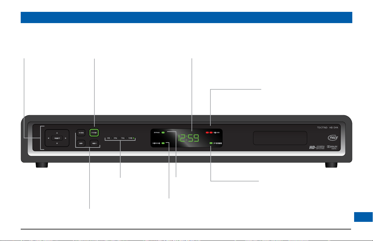
Using the front-panel buttons
You can use the buttons on the front panel to operate your set-top, if, for example, there is a problem with your remote control.
L, R, U and D
To move left/right/
up/down in an onscreen menu/guide
SELECT button
To select items in
menus/guides
GUIDE
To display an on-screen guide
INFO
To display on-screen information
MENU
To display on-screen menus
POWER button
To turn your set-top on/off
POWER light (around button)
Lights green when your set-top is
on; red when your set-top is off;
not lighted when your set-top is
disconnected from the power supply
Resolution lights
Relevant one lights up
to show the resolution
of the picture
(for live program or
play-back program)
MESSAGE light
Lights when there is an unread message
and when you make User Settings
front-panel display
Appears when your set-top is turned on
Shows the program channel number or the time
Also displays HDTV settings (see page 21)
BYPASS light
Lights when RF Bypass is on
RECORD lights
Light red to show whether one or two
programs are being recorded
IR RECEIVE light
Lights when your set-top
is receiving a signal from
your remote control
17
Page 20

OPERATING YOUR SET-TOP (cont.)
Using your set-top’s DVR functions
Your set-top has an internal hard disk that you can use to record and play back television programs,
giving you much more control of your viewing experience. For example, you can pause live television
and resume viewing from the point at which you left off. You can record many more hours than you
can by using a VCR or DVD recorder. There are red lights on your set-top’s front panel to show
when recording is taking place. With your set-top you can:
• pauseliveTV;
• instantlyreplayliveTV;
• fast-forwarduptothepointofliveTV;
• watchasceneinslowmotion;
• rewindthroughaprogramyouhavebeenwatching;
• recordhighdenitiondigitalpictures(aswellastheregularstandarddenition);
• recordoneprogramwhilewatchinganother;
• recordtwoprogramswhilewatchingapreviouslyrecordedprogram;
• scheduleyourset-toptorecordaprogramorawholeseries;
• fullymanageyourstoredrecordings;
• backupyourdigitalrecordingstoaVCRorDVDrecorder;
• retainfullcontroloveranyparentalviewingrestrictionsyouhavesetup.
Youcontrolyourset-top’sDVRfunctionsusingyourremotecontrol;consulttheinformationsupplied
by your cable service-provider for more details. Also read the operating instructions that are supplied
with your remote control.
18
NOTES
The exact functionality of the
DVR (digital video recorder)
in your set-top depends on
your on-screen program guide.
For more details, consult the
information supplied by your
cable service-provider.
Do not confuse recording to the
hard disk with recording to a
separate VCR or DVD recorder,
as mentioned on page 20.
The DVR functions will not
work if your set-top becomes
overheated. The internal hard
disk will be temporarily disabled.
Refer to the set-top’s ventilation
requirements on page 4.
Page 21

OPERATING YOUR SET-TOP (cont.)
Formatting the Hard
drive. Please
wait...
Do you want to format the
external hard drive?
YES
NO
Using an external hard disk
Your cable service-provider may enable a feature that allows an external hard disk to work with your
set-top. If this is the case, most major brands of serial ATA hard disk, connected to the SATA por t, are
supported. You should not connect an external hard disk to the USB port.
If you do use an external hard disk, it gives extra recording capacity, but you cannot choose which
disk (internal or external) your set-top will record to. It will automatically choose the one with more
empty space. The recordings on the external hard disk are uniquely linked to the set-top on which
they were made, so you cannot play them back or delete them with a different set-top.
Connecting an external hard disk
1. First stop any recording you are making to your set-top’s internal hard disk.
2. Turn off your set-top with the POWER button and then wait 60 seconds before disconnecting
it from the wall AC socket. (You must not “hot plug” an external hard disk).
3. Connect the external hard disk, using an appropriate cable, to the SATA connector on your settop.
4. Apply power to the external hard disk.
5. Reconnect your set-top to the wall AC socket and turn it on with the POWER button.
If the external disk needs formatting, your set-top will inform you by means of a pop-up dialog box on
your TV screen (see right).
6. Use the arrow and SELECT buttons to select YES, and the formatting will begin.
19
Page 22
OPERATING YOUR SET-TOP (cont.)
Using RF Bypass
You can use RF Bypass to watch the regular (analog) channels that are included in the cable service.
Itmakesthesechannels“bypass”yourset-topandpassdirectlytoyourTVand/orVCR.
To use RF Bypass:
• Yourset-topmustbeinstalledwiththecorrectconnectionsfromtherearpaneltoyourTVor
VCR(seethenote,right);and
• TheRFBypassfeaturemustbeon(youmayneedtosetitto“On”intheSetupmenu;seepage35).
A BYPASS light on your set-top’s front panel lights up green if RF Bypass is on. Your remote control
may have a button that allows you to turn Bypass on and off.
For you to start using RF Bypass, your set-top must be turned on. However, if the RF Bypass feature
has been set to “On”, RF Bypass will work even if you turn your set-top off.
When RF Bypass is on: you can use your TV’s remote control to tune to any of the available regular
(analog) channels and watch that channel on your TV (the path is the RF cable). You can, at the same
time, use your set-top’s composite video and L & R audio outputs to record on your VCR the digital
channel that your set-top is tuned to. (This channel number is shown on your set-top’s front panel.*)
This means that, when the Bypass is on, you can watch a regular (analog) channel on your TV and, at
the same time, record a digital channel on your VCR. (If you are recording to the hard disk, you can
record two different programs to it, while watching an analog channel on the bypass.)
When RF Bypass is off: you see on your TV the channel that your set-top is tuned to. This is the same
channel that your VCR receives. So, when RF Bypass is off, you can record on your VCR only the
program that you are watching on your TV (but you can still record a different one to the hard disk).
NOTE
If you are not sure whether your
set-top has been set up to allow
RF Bypass, check your installation.
If there is a cable (RF cable)
going from the TO TV connector
on your set-top’s rear panel to
your TV (or to your VCR and
TV, as shown by the dashed line
on pages 12 and 13) then RF
Bypass is correctly set up. Your
TV and VCR also need to have
been tuned to your set-top’s VHF
output channel (3 or 4, depending
on your location).
NOTE
* If the “Front LED Display” (see
page 35) is set to “Current Time”,
you will not see the channel
number. To see the number of
the channel your set-top is tuned
to, you should set “Front LED
Display” to “Current Channel”.
20
Page 23

MAKING USER SETTINGS
PACE USER SETTINGS
TV Aspect Ratio
TV Display Capability
Auto Pillarbox
Closed Captions
Front Panel Brightness
Hard Disk Sleep Mode
HDMI Settings
Restore Defaults
Select[OK] Exit[POWER]
About User Settings
Your installer should have made the correct settings to make sure your set-top is compatible with
your HDTV or TV. However you may wish to change some settings, for example if you purchase a
new HDTV. You can make the following settings and you can also reset them to the factory defaults.
• TVAspectRatio(thescreen’swidth-to-heightratio,orshape)
• TVDisplayCapability(screenresolution)
• AutoPillarbox
• ClosedCaptions
• FrontPanelBrightness
• HardDiskSleepMode(forenergysaving)
• HDMISettings
You use the buttons on the front panel of your set-top to make the settings and you can see them on
the front-panel display. You can also look at on-screen menus, but please note that, until your set-top
has been set up to match the display capability of your TV, these menus may not be visible.
Putting your set-top into “user settings mode”
1. Make sure that your set-top is turned on (POWER light is green).
2. Press the POWER button on your set-top, then, within 1 second, press the MENU button.
“ASPt” (or another of the 8 “words” shown right) should then appear on the front-panel display. If it
does not appear, press the MENU button again. You may also see the PACE USER SETTINGS menu,
shown right, on your TV screen.
3. When you have finished making changes (see pages 22 to 31), press the POWER button to
remove the PACE USER SETTINGS menu and return to normal viewing.
POWER button.
MENU button front-panel display
21
Page 24
TV Aspect Ratio
4:3
>16:9
SELECT
SELECT
SELECT
SELECT
MAKING USER SETTINGS (cont.)
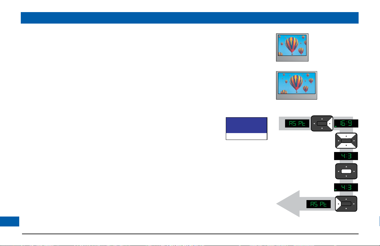
About the TV Aspect Ratio
The TV that you have connected to your set-top has an aspect ratio (width-to-height ratio) of 4:3
(basic/standard)or16:9(widescreen).YoumustsettheappropriateTVAspectRatio(4:3or16:9)on
your set-top, so that it is compatible with your TV.
Setting the TV Aspect Ratio
If you have not done so, put your set-top into “user settings mode”, as described on page 21.
Press the U or D button until the front panel shows “ASPt”.
The flow diagram on the far right shows how you use the arrow and SELECT buttons on your
set-top’s front panel to change the display and make the settings. See also the instructions below.
1. To change the TV Aspect Ratio, press the R button.
ThecurrentTVAspectRatiosetting(“4:3”or“16:9”)appearsonthefront
panel. Whenever the current setting is displayed, the MESSAGE light will be
lighted. You may also see the menu, shown right, on your TV screen. In the
menu, the current setting has > in front of it.
2. Press the U or D button until the TV Aspect Ratio you want appears on
the front panel.
3. Press the SELECT button to confirm your choice and change to that TV
Aspect Ratio.
4. Press the L button. The front panel will display “ASPt” again.
5. To continue making the settings, see the next section.
22
4:3 standard TV,
EDTV or HDTV
16:9 HDTV
Page 25
MAKING USER SETTINGS (cont.)
About TV Display Capability (resolution settings)
• Your set-top can transmit pictures to your TV in a range of resolutions (also called “Display
Capabilities” - see below for the settings available). Generally, higher screen resolutions give better
quality pictures. However, the quality will always depend on how the program was originally
transmitted.
• Different TVs display different screen resolutions. For example, standard TVs display “480i”, EDTVs
(Enhanced Definition TVs) display “480p” and most HDTVs display “1080i” or “720p”. Many
HDTVs will display at more than one resolution. For more information, see the information
supplied with your HDTV.
You must make the appropriate TV Display Capability setting(s) on your set-top, so that it is
compatible with your TV. See the next page for full instructions.
In order to display the best picture every time, you should select every resolution that your TV is
capable of displaying. This should ensure that programs are displayed with the minimum distortion.
There are green lights on your set-top’s front panel to show you the resolution of the picture for the
program your set-top is currently handling (a live program or one you are playing back).
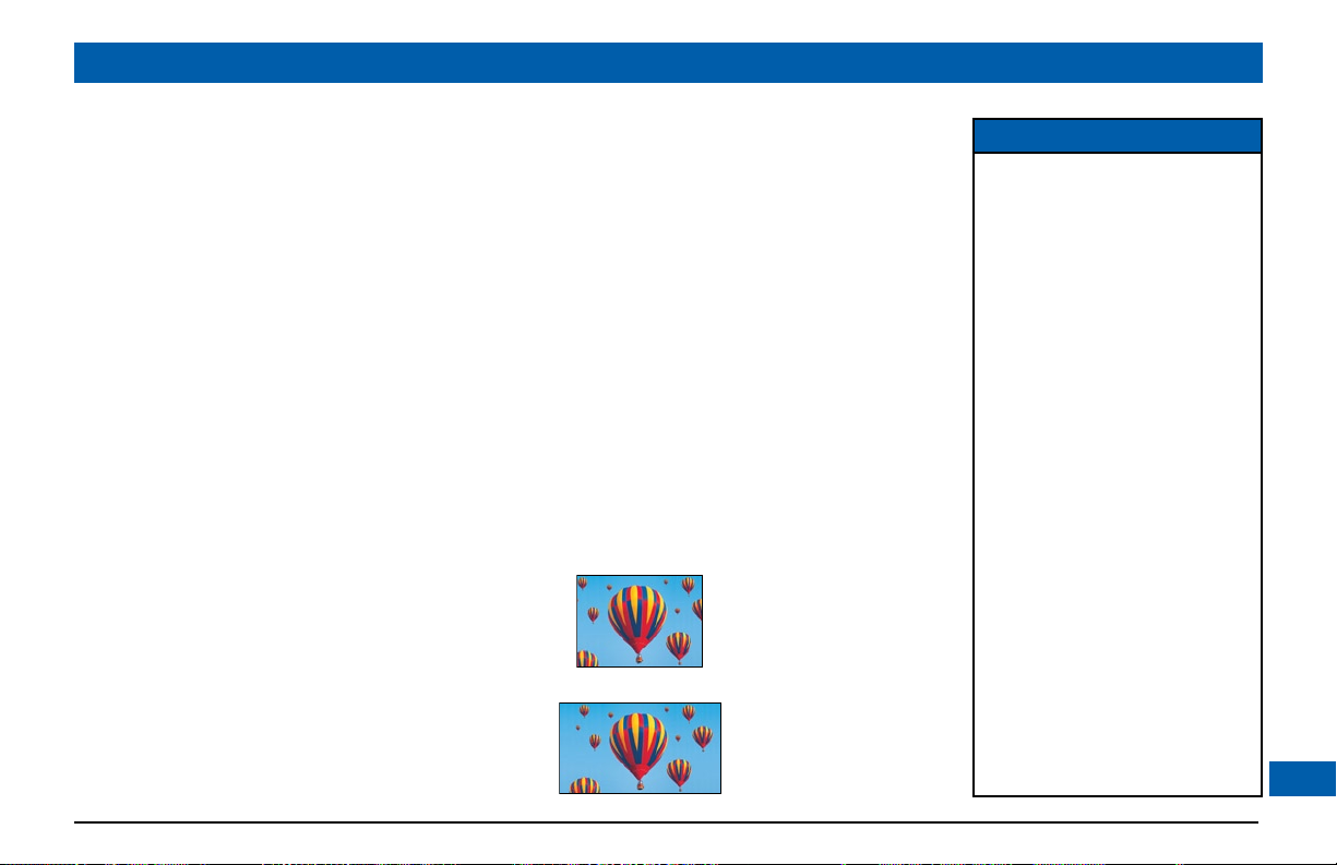
TV Display Capability settings
• 480i is standard definition NTSC and is
transmitted in a 4:3 aspect ratio (see right)
• 480p is enhanced digital TV and can be
transmittedineithera4:3or16:9aspectratio
• 720p and 1080i are HDTV and are
transmittedina16:9aspectratio(seeright)
480i transmission:
The aspect ratio is 4:3
1080i transmission:
The aspect ratio is 16:9
NOTE
When your HDTV is connected
to your set-top via an HDMITM,
your set-top gets information
from your HDTV about the
HDTV’s display capability. Your settop uses this information to adjust
its TV Display Capability settings.
Your set-top also records your
HDTV’s ID (identification), so that
only one HDTV is supported at any
one time. When your HDTV has
updated your set-top’s TV Display
Capability settings, you may change
them if you wish. Your changes will
then be stored with the ID.
You can restore your set-top’s
TV Display Capability settings to
their factory values, as described
on page 32. You can also restore
your set-top to the settings that
your HDTV has passed to your
set-top. To do this you must first
restore the factory settings while
your set-top is disconnected from
your HDTV, then reconnect your
HDTV via an HDMI
TM
cable.
23
Page 26
TV Display Capability
1080i : YES
720p : NO
480p : YES
480i : YES
MAKING USER SETTINGS (cont.)
Changing the TV Display Capability
If you have not done so already, put your set-top into “user settings mode”, as described on page 21.
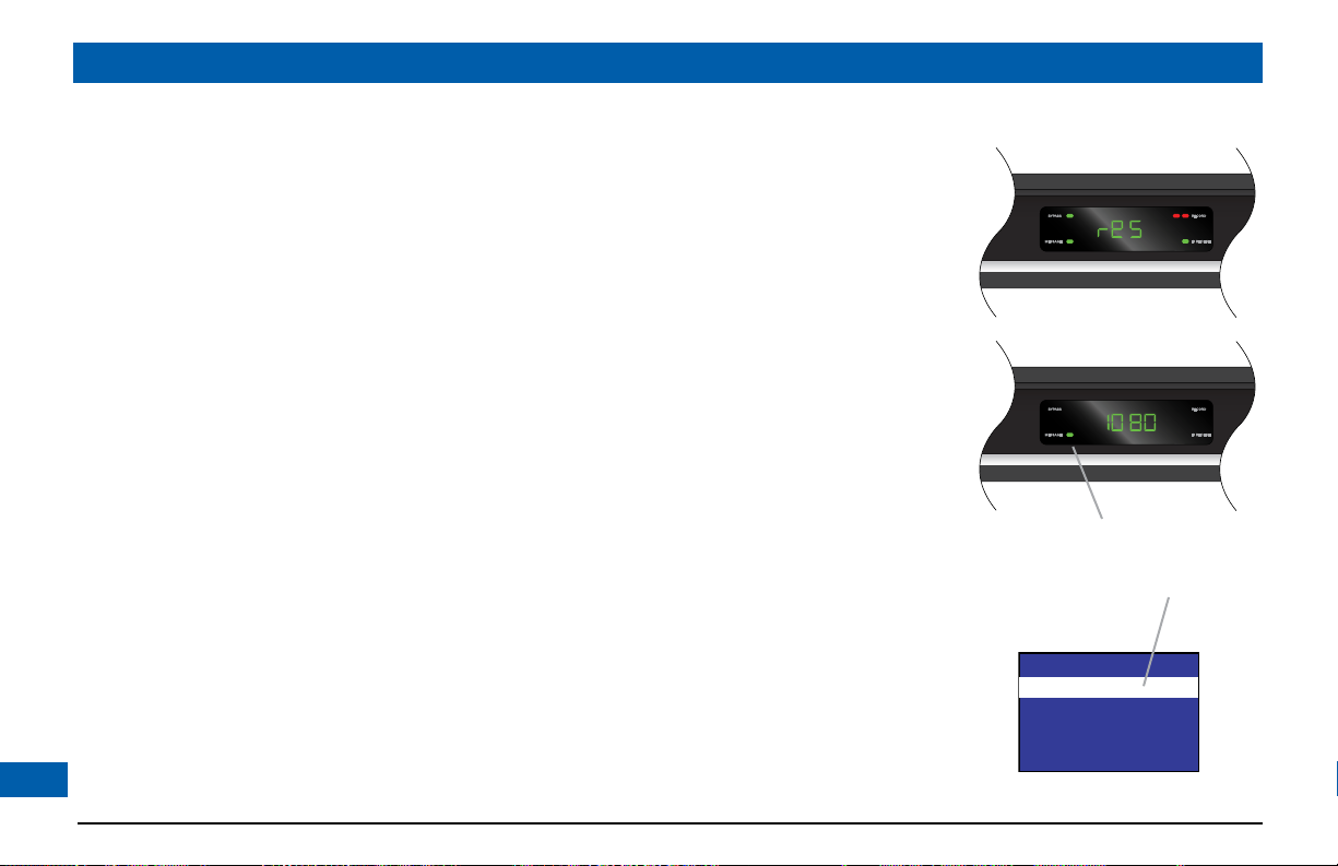
Press the U or D button until the front panel shows “reS” (short for “resolution”).
The flow diagram on page 25 shows how you use the arrow and SELECT buttons on your set-top’s
front panel to change the display and make the settings. See also the instructions below. The available
resolutions are: 1080i, 720p, 480p and 480i. (See pages 23 and 25 for more information about these.)
1. To change the TV Display Capability, press the R button when you see “reS” on the front
panel, as shown right.
The front panel shows the TV display capability that was last selected, so it could show 480i, 480P,
720P or 1080i (this final setting is displayed as 1080). You will probably also see the TV Display
Capability menu, shown right, on your TV screen. If you cannot see this menu, you should be able
to do so by the time you have finished making these Display Capability settings.
2. If you can see the menu, proceed as follows:
Press the U or D button to highlight each resolution in turn and, for each one, press the
SELECT button if you wish to change the setting (the setting changes between “YES” and
“NO” each time you press SELECT). If, at any stage in this process, the menu disappears from the
screen, immediately press SELECT to restore the menu.
3 If you press the R button when you see “reS” on the front panel, but the menu does not appear
on your TV screen, proceed as follows:
Press U or D until “1080” is displayed on the front panel, then press SELECT.
If the menu then appears, check and change the settings as described in Step 2 above.
If the menu does not appear at this stage, press SELECT again, then press U or D until “720P” is
24
displayed on the front panel, and then press SELECT. If the menu then appears, check and change
the settings as described in Step 2 above. Repeat this process until you have tried all the resolutions.
If the displayed resolution is
currently set, the MESSAGE light
will be lighted and YES will be in
the menu
Page 27

MAKING USER SETTINGS (cont.)
SELECT
SELECT
SELECT
SELECT
TV Display Capability
1080i : YES
720p : NO
480p : YES
480i : YES
TV Display Capability
1080i : NO
720p : NO
480p : YES
480i : YES
4. When you are satisfied that all the TV resolutions are correct, press the L button. The front panel
shows “reS” again. To continue making the settings, see page 26.
This diagram shows an example only. Please make
sure that, for each resolution, you select the correct
setting (yes or no) that applies to your TV.
The on-screen
menu shows the
selected setting.
Further information about the TV Display Capability
The TV Display Capability settings relate to equipment that is connected to the HDMITM and
COMPONENT VIDEO OUT connectors because the settings control the output at those
connectors. If equipment is connected via an HDMITM cable, that equipment may also pass
information back to your set-top, which may affect what settings are available.
Generally, the TV Display Capability settings do not affect equipment connected to the VIDEO OUT
and S-VIDEO jacks, because the output at these jacks will always be the standard definition 480i.
25
Page 28
4:3 transmission 16:9 TV with no automatic
detection of 4:3,
Auto-pillarbox switched off
16:9 TV with no automatic
detection of 4:3,
Auto-pillarbox switched on
MAKING USER SETTINGS (cont.)
Auto Pillarbox
YES
>NO
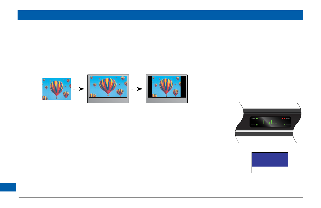
Setting Auto Pillarbox
IfyourTVisa16:9TVthatdoesnotautomaticallydetect4:3transmissions(andthereforedoes
not add black bars to the sides of the picture), then 4:3 transmissions may display “stretched” to fit
the16:9screen.Ifyoudonotwantthiseffect,youcansetyourset-toptoaddblackbarstothe4:3
picture,sothatitistransmittedtoyourTVata16:9aspectratio.Seetheexamplebelow.
Changing the Auto Pillarbox setting
If you have not done so already, put your set-top into “user settings mode”, as described on page 21.
1. Press the U or D button until the front panel shows “PiLL”, as shown right.
2. Press the R button.
The current Auto Pillarbox setting (“YeS” = switched on, or “no” = switched off) is displayed on
26
the front panel. If you can see the on-screen menus, the menu shown right appears.
> shows current setting, as does
a lighted MESSAGE light
Page 29
MAKING USER SETTINGS (cont.)
4:3 transmission 16:9 TV with no automatic
detection of 4:3,
Auto-pillarbox switched off
16:9 TV with no automatic
detection of 4:3,
Auto-pillarbox switched on
Use 'Zoom' to increase the picture size.
(Note: the picture may lose some
definition due to the expansion)
3. If you want to change the setting, press U or D. Press the SELECT button to confirm the
choice and change to the new setting.
4. Press the L button. The front panel shows “PiLL” again.
To continue making the settings, see the next section.
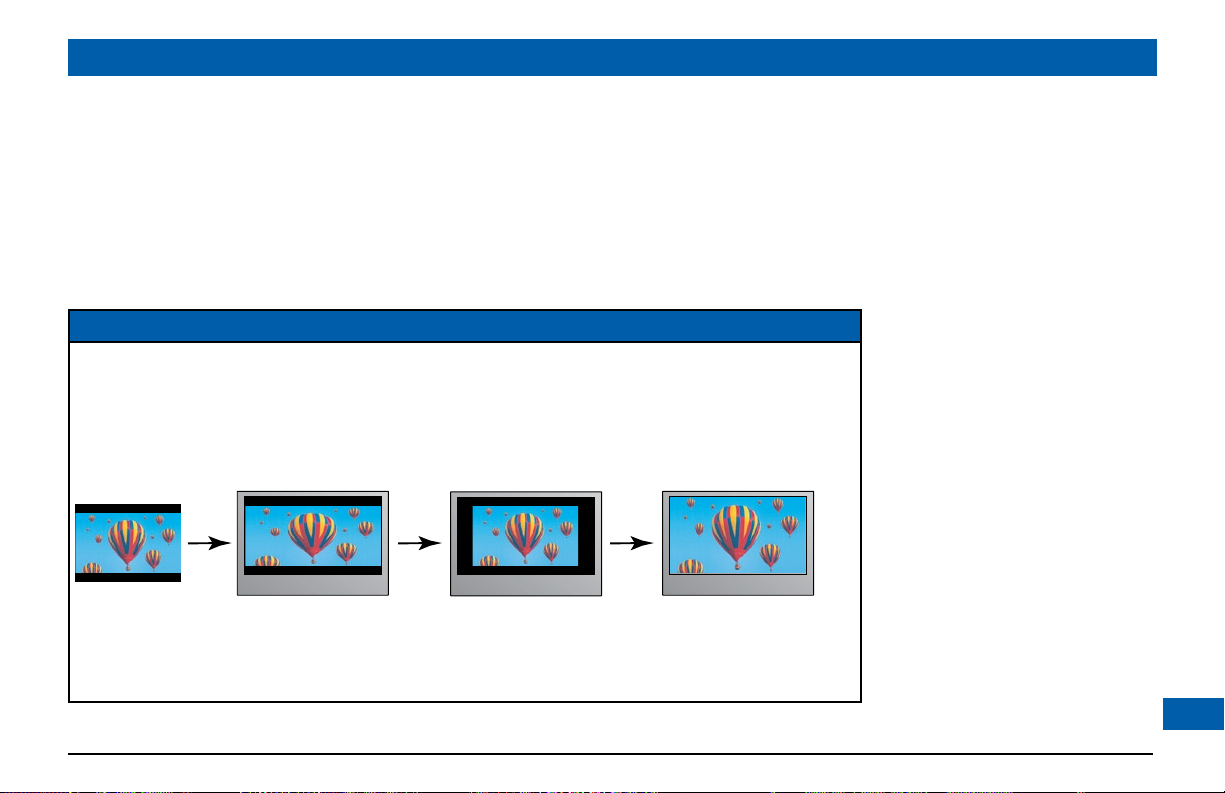
NOTE
16:9 picture in a 4:3 transmission
Sometimes 4:3 transmissions may contain a 16:9 picture, with black borders at the top and bottom. On a
16:9 TV this may display with black borders all the way around the picture. To remove these borders, you
can use the “Zoom function” button on your remote control (could be labeled Zoom or Aspect).
See the example below. For more information about using “Zoom”, see page 34.
27
Page 30
Closed Captions
CC : OFF
Configure Captions
MAKING USER SETTINGS (cont.)
Configure Captions
Size : Small
Font : Style 1
Character Color : White
Character Shading : Auto
Background Color : Black
Background Shading : Auto
Std Def CC : Auto
Hi Def CC : Service 1
Reset to Defaults
Closed Caption Example
Making Closed Caption Settings
Closed captioning is a means of displaying alerts and subtitles on your TV screen, superimposed on
whatever you are watching. You can turn closed captions on or off, as required, and you can also
change the closed captions’ appearance.
Turning closed captions on or off
If you have not done so already, put your set-top into “user settings mode”, as described on page 21.
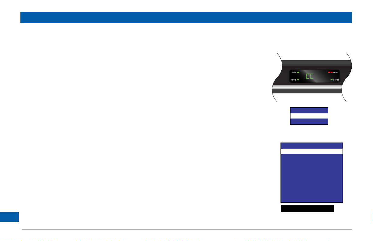
1. To change the Closed Captions setting, press the D button until the front panel shows “CC”, as
shown right.
2. Press the R button. The current Closed Captions setting, either “on” (switched on) or “oFF”
(switched off) is displayed on the front panel. If you can see the menus, the Closed Captions
menu appears, see right.
3. If you want to change the setting, press the SELECT button - the setting changes.
4. Press the L button. The front panel shows “CC” again.
To continue making the settings, see the next section.
Changing the closed captions’ appearance
If you want to change the closed captions’ appearance, we recommend you use the on-screen
menus, rather than the front-panel display. You can see the effect of your settings by looking at the
example below the menu.
1. In the Closed Captions menu (see above), press the D button to highlight “Configure Captions”,
28
then press SELECT. The Configure Captions menu, shown right, appears.
Page 31

MAKING USER SETTINGS (cont.)
Front Panel Brightness
Standby Level : Std
Viewing TV Level : High
2. Use the U and D arrows to highlight each option in turn. Use the SELECT button to choose
the setting you want (the setting changes each time you press SELECT).
3 If you wish to reset all the Closed Caption settings to their default values (mainly Auto), press the
D button to highlight “Reset to Defaults” in the menu, then press SELECT.
4. When you have made all the changes you want to make, press L twice to re-display the PACE
USER SETTINGS menu.
Setting Front Panel Brightness
You can use the Front Panel Brightness menu to set the brightness level of the front-panel display
when your set-top is being used (“Viewing TV” level) and when it is switched off (“Standby” level).
1. If you have not done so already, put your set-top into “user settings mode”, as described on page
21. Then press the U or D button until the front panel shows “brit”, as shown right.
2. Press the R button. The Front Panel Brightness menu, shown right, appears.
3. Press the U or D button to highlight “Standby Level” or “Viewing TV Level” as required.
4. Use the SELECT button to choose the setting you want (the setting changes each time you
press SELECT): “Low”, “Std” (Standard) or “High”. Look at the dimming and brightening of the
front-panel display while you are making the settings, to see the effect of your selections.
5. When you have made all the changes you want to make, press L to re-display the PACE USER
SETTINGS menu.
29
Page 32

MAKING USER SETTINGS (cont.)
Standby Sleep Mode
>YES
NO
Setting Hard Disk Sleep Mode
If your set-top is in Hard Disk (Hdd) Sleep Mode, the internal hard disk (and any attached external
hard disk) will receive no power when you switch off your set-top (that is, when the front-panel
POWER light is red and the set-top is in standby). This is an energy-saving feature.
If you have set up your set-top to make recordings, the set-top and hard disk will switch on to allow
those recordings to be made, even if this “Standby Sleep Mode” feature is on (set to “YeS”). However.
it will take a little more time to do so, compared with having Standby Sleep Mode off (set to “no”).
1. If you have not done so already, put your set-top into “user settings mode”, as described on page
21. Then press the U or D button until the front panel shows “Hdd”, as shown right.
2. Press the R button.
The current Standby Sleep Mode setting (“YeS” = switched on, or “no” = switched off) is
displayed on the front panel. If you can see the on-screen menus, the menu shown right appears.
3. If you want to change the setting, press U or D. Press the SELECT button to confirm the
choice and change to the new setting.
4. Press the L button. The front panel shows “Hdd” again.
5. When you have made all the changes you want to make in the Standby Sleep Mode menu, press
the L button to re-display the PACE USER SETTINGS menu.
> shows current setting, as does
a lighted MESSAGE light
30
Page 33

MAKING USER SETTINGS (cont.)
HDMI Settings
Audio Output Mode : Auto
Disable Auto Detect : NO
Changing HDMI Settings
You can use the HDMI Settings menu to choose an Audio Output Mode, and to enable or disable
automatic detection of a newly connected HDTV (when using an HDMI
1. If you have not done so already, put your set-top into “user settings mode”, as described on page
21. Then press the U or D button until the front panel shows “hdni”, as shown right.
2. Press the R button. The HDMI Settings menu, shown right, appears.
3. Press the U or D button to highlight “Audio Output Mode” or “Disable Auto Detect” as
required.
4. Use the SELECT button to choose the setting you want (the setting changes each time you
press SELECT):
Audio Output Mode has three possible settings:
“Auto” (provides the audio format best suited to the connected equipment)
“LPCn” (provides PCM audio only)
“PASS” (maintains the original incoming-audio format)
Disable Auto Detect is either “YeS” or “no”.
5. When you have made all the changes you want to make, press L to re-display the PACE USER
SETTINGS menu.
TM
cable).
Removing the User Settings menus
When you have finished making all the user settings you wish to make, press the POWER button
to remove the PACE USER SETTINGS menu and return to normal viewing.
31
Page 34

MAKING USER SETTINGS (cont.)
Restoring the factory default settings
If you wish, you can restore the user settings to their factory defaults. All the changes you have made
will be lost and the settings will revert to those that were programmed in the factory. The factory
settings are:
PACE USER SETTINGS menu item Options Factory default setting
TV Aspect Ratio – 16:9
TV Display Capability 1080i
720p
480p
480i
Auto Pillarbox – No
Closed Captions – Off
Configure Captions Various All Auto except Hi Def CC,
Front Panel Brightness Standby Level
Viewing TV Level
Hard Disk Sleep Mode (Standby Sleep Mode) - Yes
HDMI Settings Audio Output Mode
Disable Auto Detect
Yes
No
Yes
Yes
which is Service 1
Std
High
Auto
No
To restore the factor y default settings, follow the instructions on page 33.
32
Page 35
MAKING USER SETTINGS (cont.)
SELECT
SELECT
SELECT
If you have not done so, put your set-top into “user settings mode”, as described on page 21.
The flow diagram on the right shows how you use the arrow, SELECT and POWER buttons on
your set-top’s front panel to change the display and make the settings. See also the instructions below.
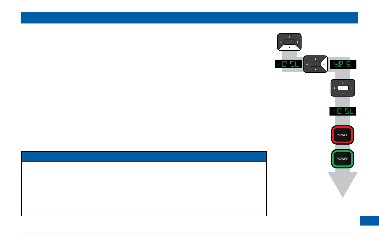
1. Press the D button until the front panel shows “reSt” (short for “restore factory settings”), as
shown right.
2. Press the R button. “YeS” appears on your set-top’s front panel. (If you no longer wish to restore
the factory settings, press the L button.)
You may also see this message on your TV screen: “Restore Default. Press OK to confirm”
3. To confirm and restore the factory settings, press the SELECT button.
The factory settings are restored, and the PACE USER SETTINGS menu reappears.
4. If you want to continue changing the settings, see the sections from page 21 onwards. If you have
finished changing the settings, press the POWER button. Your set-top will switch on with the
restored settings.
NOTES
If your set-top and HDTV are connected via a standard HDMITM cable, your HDTV may pass information
about the required settings back to your set-top (see page 23). If you wish to restore your set-top’s
settings to those created by your HDTV, you should disconnect your set-top from your HDTV before
you restore the factory default settings. When you reconnect your HDTV to your set-top via the HDMITM
cable, your HDTV will pass back the information again.
Always turn off your set-top, wait 60 seconds, then disconnect your set-top from the wall AC
outlet before you connect or disconnect any other equipment to or from its rear panel.
33
Page 36
USING ZOOM
Using “Zoom” to change the picture
Making the appropriate TV Aspect Ratio and TV Display Capability settings (see pages 21 through
27) should ensure that the picture on your TV screen is not distorted (stretched or squashed) and
that it fills as much of the screen as possible.
However, even if you have selected the correct settings, there will be times when a program appears
with black borders either at the top and bottom or at the sides of the picture (or sometimes even all
the way round the picture). This happens because the aspect ratio (shape) of the transmitted program
does not match the aspect ratio of your HDTV, or because the transmitted programme includes
black borders as part of the transmission (see right).
Your remote control should have a “zoom function” button (could be labeled Zoom or Aspect),
which you can use to change the TV picture until it appears as you want it to.
1. Press the “zoom function” button once to change the display.
2. Press it again to change the display again. Continue to press it in this way until the picture appears
as you want it to.
Note: The effect that this button has on transmissions depends on the transmission itself. On some
transmissions it may have no effect at all.
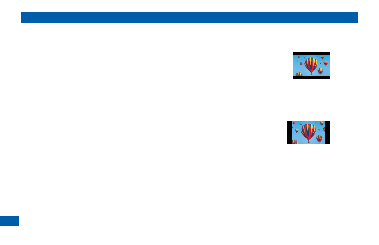
A 4:3 transmission, with
a 16:9 picture. Dark bars
are added at the top and
bottom of the transmission
A 16:9 transmission,
with a 4:3 picture in it.
Dark bars are added
at the sides of the
transmission
34
Page 37

USING THE SETUP MENUS
In addition to the user settings described on pages 21 through 33, setup menus may be available in your on-screen guide. These should be
described in the information provided by your service-provider. There may also be on-screen information to explain these menus.
However, certain settings may affect how your set-top and TV work. See the table below for information about typical menu items and
settings (they depend on which on-screen guide is running on your set-top, so may vary from those given below).
Item Options Settings Notes
Cable Box
Setup
Audio Default Audio
Screen position This allows you to adjust how the picture displays on your TV screen.
Other items and options may be available on these screens. The menus may be subject to change in the future, as your set-top advances with new technology.
Front LED
Display
AC Outlet Switched,
RF Bypass Off, On This must be “On” before you can use RF Bypass.
Configuration Allows you to view the configuration of your set-top.
Track
Optimal
Stereo
Audio
Output
Current Time,
Current Channel
Unswitched
Channel Default,
English, various
other languages
TV Speakers,
Stereo, Advanced
If setting is “Current Time”, the time is displayed on the front panel when your set-top is
switched on. If setting is “Current Channel”, the program channel number is displayed.
If setting is “Switched”, the AC outlet on your set-top’s rear panel is on when your set-top
is on, and off when your set-top is off, so any TV that is therefore receiving its power from
this AC outlet will switch off when your set-top is turned off. If setting is “Unswitched”,
the AC outlet is always on, so any TV that is receiving its power from this AC outlet will
continue to receive power whether your set-top is switched on or off.
For information about RF Bypass, see page 20.
Sets the language track that your set-top first attempts to use when tuning to a channel.
“Channel Default” means your set-top will use the default audio track for the program.
Selecting a language means it will use the corresponding language track, if available.
Selecting this option enables your set-top to regulate the volume to minimize sudden
changes in volume, for example during a commercial break.
If you select “Advanced”, further settings are displayed, allowing you to set the Compression
(to None, Light or Heavy) and the Stereo Output (to Mono, Stereo or Matrix Stereo).
35
Page 38

SOLVING PROBLEMS
If the installed system does not seem to be working properly, first make sure that all the cables are securely connected, then carry out the
following checks, in the order shown.
Check Suggested solution Further checks, if there is still a problem
Is anything lighted on
your set-top’s front
panel?
YES
NO
Power may not be reaching your set-top.
Make sure that the power cord is properly
R
plugged in. If there is a switch by the wall AC
power outlet, switch it to ON.
Check that the wall AC power outlet is working (for
example by plugging in a lamp).
D
Does your remote
control operate your
set-top?
YES
D
Please see the next page
NO
Your set-top may not be turned on.
Check if the light around the POWER
R
button on the front panel is green. If it is red,
press the POWER button on the front panel
to turn on your set-top.
Check that nothing is blocking the path from your remote
control to the front panel.
Check that your remote control is currently set to
operate your set-top (consult the instructions supplied
with your remote control).
If your remote control will still not operate your set-top,
replace the batteries in your remote control.
If there is still a problem, try to operate your set-top
by using its front-panel buttons. If this works, then your
remote control may be faulty.
36
Page 39

SOLVING PROBLEMS (cont.)
Check Suggested solution Further checks, if there is still a problem
Can you see a picture on
your TV screen?
YES
D
Please see the next page
NO
Your TV and other equipment may not be
turned on. Check that they are plugged into
R
AC power outlets and turned on.
Note: If you have connected your TV to the
POWER OUTLET (AC outlet) on your settop, when you turn off your set-top, your TV
may turn off automatically, if the “AC Outlet”
is set to “Switched” (see page 35). You may
wish to keep this feature, or you may wish to
set “AC Outlet” to “Unswitched”.
Make sure the Bypass feature is turned OFF (the BYPASS
light on the front panel is not lighted).
Check that you have selected the appropriate AV input on
your TV: HDMI
video or S-video (depending on how your system is
connected up).
If you are using a component video (YPbPr) connection,
make sure the set-top’s TV Display Capability settings are
appropriate for your TV (see page 24).
If the video path between your set-top and your TV loops
through other equipment (such as a VCR), you may need
to turn off this equipment for the loopthrough to work.
If you are using the HDMI
connection goes directly from your set-top to your TV. If
your set-top detects that the link is not secure, your settop will not transmit a picture (see page 11). If you expect
the link to be secure, try disconnecting and reconnecting
the HDMITM cable.
TM
, component video (YPbPr), composite
TM
connection, make sure the
37
Page 40

SOLVING PROBLEMS (cont.)
Check Suggested solution Further checks, if there is still a problem
Is the picture distorted
or too small?
NO
D
Can you display menus
and guides on the
screen?
YES
D
Is there any sound?
YES
YES
NO
NO
Check that the TV Aspect Ratio and TV
Display Capability, as set on your set-top,
R
are appropriate for your TV (see pages 21
through 25). Change them if necessary.
If your TV is connected to the VIDEO OUT
or S-VIDEO jacks, then you will see menus
R
and guides only if the screen resolution 480i
is set to “Yes” and 480p, 720p and 1080i
are set to “No”.
Check that the audio cables are securely and
correctly connected.
R
If your TV is a 16:9 TV, you can use Auto Pillarbox to add
black borders to 4:3 transmissions, so that the picture is
not stretched (see page 26).
If the TV Aspect Ratio and TV Display Capability settings
are correct, try using Zoom to improve the picture (see
page 34) or consult the instructions that came with your
TV and try adjusting your TV’s display.
Use the front panel to check the user settings (see page
21) and change the TV Display Capability resolution
settings if necessary (see page 23).
Check that you have not muted the sound on your settop and/or TV. Adjust the volume control on your set-top
and/or TV. If you are using a home theater receiver, check
it is set up correctly.
D
Can you hear stereo
sound?
YES
D
Please see the next page
38
NO
First check that the program is likely to have
stereo sound (an old movie, for example, may
R
not be in stereo).
Check the on-screen Setup Menu, Audio
settings (see page 35). The Stereo Output
may be set to “Mono”. Change it to “Stereo”.
If your TV is mono, you will hear stereo sound only if
you have a stereo audio amplifier and speakers or home
theater connected to your stereo VCR or set-top.
Page 41

SOLVING PROBLEMS (cont.)
Check Suggested solution Further checks, if appropriate
Can you see and hear a
DVD that you are trying
to play?
YES
NO
Check that all the audio and video cables are
securely and correctly connected, including
R
any to a home theater receiver that you may
be using to enhance the sound.
D
Is the picture low quality,
or “fuzzy”, when you
are expecting to see an
HDTV-quality picture?
NO
D
Can you see only regular
(analog) channels but not
any digital channels?
NO
YES
YES
Some programmes may include “copy
protection” which means, if your set-top is
R
connected to your HDTV via the component
video jacks, the picture is downgraded to
standard TV quality. To prevent this from
happening, use an HDMITM (high definition
multimedia interface) connection instead.
The Bypass feature may be turned on (check
if the BYPASS light on your set-top’s front
R
panel is lighted). If Bypass is on, turn it off
(using the Setup menu, if there is one, or the
appropriate button on your remote control).
D
Are the DVR functions
working?
NO
The internal hard disk may be temporarily
R
disabled because the set-top has overheated.
Make sure the set-top is not overheating
(refer to the set-top’s ventilation
requirements on page 4).
39
Page 42

TERMS AND CONDITIONS FOR USE OF SOFTWARE (“TERMS”)
THE PRODUCT TO WHICH THESE TERMS RELATE (THE “PRODUCT”)
INCORPORATES SOFTWARE WHICH IS OWNED BY PACE plc (“PACE”) OR
ITS THIRD PARTY LICENSORS (THE “SOFTWARE”). BEFORE USING THE
PRODUCT PLEASE READ THESE TERMS. IF YOU DO NOT AGREE TO THESE
TERMS YOU MAY NOT USE THE PRODUCT AND SHOULD IMMEDIATELY
RETURN THE PRODUCT TO YOUR SUPPLIER. THESE TERMS ALSO APPLY TO
ANY MODIFICATIONS, UPDATES OR SUPPLEMENTS TO THE SOFTWARE
PROVIDED TO YOU. FOR PURPOSES OF THESE TERMS, “YOU” MEANS YOU,
THE END USER, AND YOUR PRODUCT SUPPLIER, UNLESS THE CONTEXT
REQUIRES OTHERWISE.
A. License Grant and Conditions
1. Pace, or your supplier, if applicable, grants you a non-exclusive, non-
transferable, limited license to use the Software solely as integrated with,
incorporated into, or provided for use in connection with the Product.
2. Pace reserves all rights not expressly granted to you under these Terms.
3. You may not transfer any of your limited rights in the Software without the
prior written consent of Pace, and if consent is provided then the Software
shall only be transferred in conjunction with the transfer of the Product
AND ONLY IF the transferee has read and agreed to accept these Terms.
4. You must ensure that the copyright, trademark and other protective notices
contained in the Software are maintained and not altered or removed.
5. The Software is protected by copyright and other laws and international
copyright and other treaties.
6. The Software provided hereunder is licensed (not sold). Pace is NOT
transferring title or any ownership rights in the Software to you.
7. All title and intellectual property rights in and to the Software and all
40
modifications, updates, enhancements and derivative works of the Software
are owned exclusively by Pace or its licensors and you agree to execute any
document reasonably requested by Pace to evidence such ownership rights.
8. Certain third party software used in connection with the Product may
be made directly available to you by operating system or other third
party providers. Use of such Software is also subject to the terms of any
applicable agreement between you and such third party.
B. License Restrictions
Except as expressly permitted herein or by statute you may not:
1. use the Software in conjunction with any other hardware or equipment
otherthantheProduct;
2. copyormodifyalloranyportionoftheSoftware;
3. incorporate all (or any portion of) the Software into other programs
developedorusedby(oronbehalfof)you;
4. reverse engineer, decompile, decrypt or disassemble the Software (or any
portionoftheSoftware);or
5. export, transfer or re-export the Software in violation of any applicable law.
C. Open Source Software
Certain components of the Software are subject to either :
(i) theGNUGeneralPublicLicence(“GPL”);
(ii) theGNULesserGeneralPublicLicence(“LGPL”);or
(iii) OpenSSL license.
The foregoing are not subject to the restrictions in Section B. In compliance with
the GPL and LGPL Pace makes the source code of the Linux software, libraries and
associated utilities it uses, together with its modifications (if any), available to the public
in source code form at: http://www.pace.com/opensource/request.
You are free to use, modify and distribute the Linux software and any modifications
Page 43

TERMS AND CONDITIONS FOR USE OF SOFTWARE (“TERMS”) (cont.)
as long as you comply with the terms of the GPL or LGPL referred to above. The
License terms applicable to (i) to (iii) above are available to you, as explained in the
section below entitled Open Source Licenses.
The Software also contains the following:
(iv) SHA library Copyright © 2000-2001, Aaron D. Gifford All rights reserved.
(v) Expat XML Parsing Librar y
Copyright©1998,1999,2000ThaiOpenSourceSoftwareCentreLtdand
Clark Cooper.
Copyright © 2001, 2002, 2003 Expat maintainers.
(vi) Expat++ This component of the Software is subject to the Mozilla Public
License Version 1.0.
(vii) Base64 Algorithm Copyright © 2001 Bob Trower, Trantor Standard
Systems Inc.
Certain additional license terms applicable to (iv) to (vi) above are available to you,
as explained in the section below entitled Open Source Licenses.
D. Termination
These Terms are effective until terminated. You may terminate these Terms by returning
the Product to your supplier. These Terms will terminate automatically without notice if
you fail to comply with these Terms or any other written agreement between you and
Pace. Upon termination you must return the Product to your supplier.
E. Disclaimer
1. EXCEPT AS SET FORTH IN ANY WRITTEN AGREEMENT BETWEEN
YOU AND PACE (OR YOUR SUPPLIER), THE SOFTWARE IS (TO THE
EXTENT PERMITTED BY LAW) SUPPLIED “AS IS” AND PACE AND
ITS LICENSORS EXPRESSLY EXCLUDE ALL WARRANTIES, EXPRESS
OR IMPLIED, INCLUDING (BUT NOT LIMITED TO) WARRANTIES OF
MERCHANTABILITY, SATISFACTORY QUALITY, FITNESS FOR PURPOSE
AND NON-INFRINGEMENT.
2. EXCEPT AS SET FORTH IN ANY WRITTEN AGREEMENT BETWEEN
YOU AND PACE, IN NO CIRCUMSTANCE WILL PACE BE LIABLE FOR
ANY DIRECT, INDIRECT, CONSEQUENTIAL, SPECIAL, PUNITIVE OR
INCIDENTAL DAMAGE (INCLUDING LOSS OF PROFITS, BUSINESS
INTERRUPTION, LOSS OF DATA OR THE COST OF PROCUREMENT
OF SUBSTITUTE GOODS, TECHNOLOGY OR SERVICES) ARISING
OUT OF THE USE OR THE INABILITY TO USE THE SOFTWARE.
F. General
These Terms are governed by the laws of the State of New York and you may only
bring claims exclusively in New York courts and Pace shall be entitled to bring a claim in
the courts of any jurisdiction. Any failure by Pace to enforce any of its rights hereunder
or applicable law shall not constitute a waiver of such rights. Pace’s licensors and
suppliers shall be third par ty beneficiaries of this License Agreement, as applicable.
YOUR USE OF THE PRODUCT CONSTITUTES YOUR ACKNOWLEDGEMENT
THAT YOU HAVE READ THESE TERMS AND AGREE TO BE BOUND HEREBY.
Open Source Licenses
The software contained in this product may be covered by certain components
consisting of free software or open source software. A list of these components
and a copy of the relevant copyright notices and license term notices that are
required by such licenses are available at this web page:
http://www.pace.com/opensource/license
This list may change from time to time and may depend on the model of product
or the version of software you have received. If you are unable to access this
web page and wish to have a copy of this list, please contact the Open Source
Administrator at: 3701 FAU Boulevard, Suite 200, Boca Raton, Florida 33431
USA. To the extent the terms of these open source or free software licenses
prohibit any of the restrictions in any end user license included with the product,
such restrictions will not apply to the applicable open source or free software
component.
41
Page 44

www.pace.com
Pace and are trademarks and/or registered trademarks of Pace plc.
502-3415800
 Loading...