

Page 1
SX-80SX-80
SX-80
SX-80SX-80
SX-80 Sodr-X-Tractor Handpiece
Operation & Maintenance InstructionsOperation & Maintenance Instructions
Operation & Maintenance Instructions
Operation & Maintenance InstructionsOperation & Maintenance Instructions
Page 2

SX-80SX-80
SX-80
SX-80SX-80
PACE Incorporated retains the right to make changes to specifications contained
herein at any time, without notice.
Contact your local authorized PACE Distributor or PACE Incorporated to obtain the
latest specifications.
The following are registered trademarks and/or servicemarks of PACE Incorporated,
Laurel Maryland U.S.A. and may only be used to identify genuine PACE products or
services:
ARM-EVAC, FLO-D-SODR, MINI-WAVE, PACE, SENSATEMP, SNAP-VAC,
SODRTEK, SODR-X-TRACTOR, THERMOFLO, THERMOJET,
THERMOTWEEZ, TOOLNET, VISIFILTER
For any questions regarding this Operation & Maintenance Manual, contact your
local authorized PACE distributor or contact PACE directly at the appropriate address
listed below.
PACE USA 9893 Brewers Court
Laurel, Maryland 20723-1990
Tel.: (301)490-9860
(888)535-7223 (PACE)
Fax: (301)498-3252
PACE EUROPE Sherbourne House, Sherbourne Drive
Tilbrook, Milton Keynes,
MK7 8HX
United Kingdom
Tel.: (44)1908 277666 Fax: (44)1908 277777
or
www.paceworldwide.com
2000 PACE Incorporated, Laurel MD. All rights reserved. Printed in the U.S.A.
2
Page 3

SX-80SX-80
SX-80
SX-80SX-80
SX-80
Sodr-X-Tractor Handpiece
Part Number 6010-0106
Manual Number 5050-0492
Rev. C
The following instructions detail the basic operational guidelines for using the
SX-80 Sodr-X-Tractor handpiece.
Introduction
The SX-80 Sodr-X-Tractor handpiece provides thermally enhanced through-hole
desoldering on extra heavy multilayer assemblies at safer, lower temperatures, even
during continuous use. It features a large, easy to replace solder trap. The SX-80
also provides safe removal of TQFP (Thin Quad FlatPack) and TSOP (Thin Small
Outline Package) surface mount components and continuous removal of old solder
from surface mount lands. Its slim-line, pencil grip design and finger actuated
vacuum switch facilitates ease of use and manipulation in tight places. The SX-80 is
a member of the PACE SensaTemp family of advanced handpieces.
CAUTION
Always return heated handpieces to the appropriate Tip & Tool Stand when not in
use. Failure to do so may cause burns to the operator, equipment or work surfaces
and may be a potential ignition source if combustible materials are nearby. Always
use this handpiece in a well ventilated area to avoid inhalation of fumes created by
solder flux.
NOTE
Always use your SX-80 Sodr-X-Tractor with a clean VisiFilter (See page 6) element.
Otherwise a deterioration in performance or damage to the unit may occur.
Select and enter your desired true operating temperature on your PACE power source.
To save tip life and reduce the possibility of damage, PACE recommends using the
lowest possible tip temperature that will provide rapid yet controllable melt of the
entire solder joint to be extracted. Begin with an operating temperature in the range
of 316°C (600°F) and adjust as necessary.
3
Page 4
SX-80SX-80
SX-80
SX-80SX-80
Handpiece Setup
Handpiece Connection
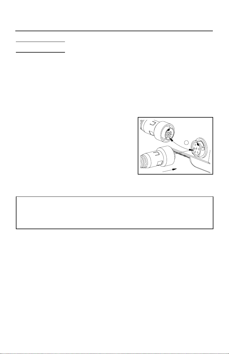
Connect the handpiece connector plug into one of the Power Receptacles on your
PACE power source in the following manner.
1. Align guide on connector with slot on power
receptacle.
2. Insert connector into power receptacle.
3. Turn the connector housing clockwise to
lock in place.
Air Hose Connection
NOTE
Insure that only one air handpiece is connected to either the Vacuum Port or
Controllable PRESSURE Port at one time. Attachment to both ports
simultaneously will cause a deterioration of performance.
To set up your SX-80 air hose connection, perform the following steps:
1. Air Hose To Handpiece Connection
a) Attach one end of a 137cm (54 inch) length of air hose to the metal
tube in the back of the handpiece.
b) If you have a PACE system incorporating only one handpiece, attach
the air hose to the SX-80 power cable using the supplied Hose Clamps
(P/N 1321-0085-01). Space them evenly along the length of the power
cable starting at a point 6 inches from the ends of the handpiece.
c) If you have a PACE system incorporating 2 or more air handpieces
(e.g., SX-80, DTP-80, TJ-70, TP-65), you may wish to leave the air hose
assembly unattached to allow a quick change to any air handpiece
being used.
4
Page 5

SX-80SX-80
SX-80
SX-80SX-80
2. Prepare a VisiFilter (P/N 1309-0028) in the following manner:
a) Connect a 1 inch (2.5cm) length of clear
pvc air hose to the FLOW OUT side of
the VisiFilter; push and turn the hose
onto the VisiFilter nipple to seat.
b) Insert the ribbed end of a male quick
connect hose mount fitting (P/N 1259-
0087) into the free end of the 1 inch
(2.5cm) length of air hose connected to
the FLOW OUT side of the VisiFilter.
c) Connect the free end of the 137cm (54
inch) length of air hose to the FLOW
IN side of the VisiFilter.
d) Insert the end of the quick connect
hose mount fitting (on VisiFilter FLOW
OUT side) into the power source
Vacuum Port.
3. When using air pressure, and/or utilizing multiple air handpieces, PACE
recommends the use of the following set up procedure which utilizes
additional quick connect hose mount fittings. An assortment of quick
connect air fittings are supplied with each additional air handpiece.
a) Disconnect the 137cm (54 inch) length of air hose from the FLOW IN
side of the VisiFilter assembly. Insert the ribbed end of a male quick
connect hose mount fitting (P/N 1259-0087) into the free end of this air
hose.
b) Connect the free end of a 1 inch (2.5cm) length of air hose with an
installed female quick connect hose mount fitting (P/N 1259-0086) to
the FLOW IN side of the VisiFilter Assembly.
c) The 137cm (54 inch) length of air hose can now be easily moved
between the VisiFilter Assembly and the Controllable Pressure Port.
The VisiFilter assembly remains connected to the Vacuum Port.
4. Additional fittings may also be added to the hose connection at the rear of
each air handpiece to ease changing of handpieces.
NOTE
When removing any air hose, turn and pull. Do not attempt to pull hose directly off.
Damage to or breakage of fitting or VisiFilter may occur. Use your SX-80 Sodr-XTractor with a clean VisiFilter element. Otherwise a deterioration in performance or
damage to the unit may occur.
5
Page 6

SX-80SX-80
SX-80
SX-80SX-80
Tip Selection
SX-80 Sodr-X-Tractor Tips come in three basic types:
1. Endura Desoldering Tips - These tips are tinnable and provide enhanced
thermal performance for thru-hole desoldering on high mass boards.
2. Endura Pik-Tips - Provides safe removal of TQFP (Thin Quad FlatPack)
and TSOP (Thin Small Outline Package) surface mount components.
3. Endura Flo-D-Sodr Tips - These tips provide rapid, continuous extraction
of old or excess solder from SMT lands.
Size selection of tips is important. For thru-hole desoldering, select a tip with an I.D.
just large enough to allow the lead to freely pass inside. The tip O.D. should not
exceed the diameter of the land to minimize risk of damage to the board substrate.
When removing TQFPs or TSOPs, the Pik-Tip should be sized so that the tip blades
make proper contact with all the lead/land connections simultaneously.
NOTE
The SX-80 Sodr-X-Tractor will only use the new Endura line of desoldering tips.
Tip Installation
For maximum productivity and proper fit, install tips into your SX-80 Sodr-X-Tractor
when the heater is hot and the Flux/Sodr trap and door are installed.
CAUTION
Hold the handpiece with the heater pointed at an
angle up to prevent injury to personnel.
1. Insert the Tip fully into heater bore using
supplied Tip Tool.
2. Gently tighten the Heater Set Screw.
3. Recheck the Heater Set Screw periodically to insure that it remains snug.
NOTE
Periodically, clean the heater bore with a properly sized wire brush (3/16" O.D.) to
insure optimum heat transfer and proper tip grounding.
6
Page 7

SX-80SX-80
SX-80
SX-80SX-80
Temperature Setting
To save tip life and reduce the possibility of damage to the PCB, PACE recommends
using the lowest possible tip temperature that will provide rapid yet controllable melt
of the entire solder joint. Begin with an operating temperature of 316°C (600°F) and
adjust as necessary. Tip temperatures in excess of 399°C (750°F) may cause damage.
For safest removal, some components on extra heavy assemblies may require
preheating or auxiliary heating.
Tip Cleaning
During heavy, continuous desoldering, on boards with flux residues or other
contamination, the tip may occasionally become clogged with such material. If
this should occur, clean the tip with the Tip Cleaning Kit (PACE part number
6993-0200) by inserting the wire tool into the tip end.
Special Applications
If you require assistance in the use of this handpiece or with a special application,
contact PACE Technical Support at:
Telephone: 1(888)535-7223 (toll-free)
Fax: (301)604 - 8782
7
Page 8

SX-80SX-80
SX-80
SX-80SX-80
Replacing the Disposable Flux/Sodr Trap
As the Sodr-X-Tractor is used, solder and flux build-up will begin to impede the
airflow and decrease system performance. The SX-80 utilizes a disposable chamber
which makes maintenance of the SX-80 a quick and simple process. Regular
replacement of the Sodr-Flux Trap will keep the Sodr-X-Tractor operating at peak
performance. To replace the Sodr-Flux Trap follow the procedures outlined below.
1) While holding the Sodr-X-Tractor with the tip facing away from you and the
handpiece in an downward
position, remove the door
assembly from the handpiece.
This action is accomplished by
pulling the plunger lock
approximately ¼” and turning it
approximately ten (10) degrees to
the right or left. The door
assembly can now be removed by
simply gripping the door near the
ear shaped protrusions and lifting
straight up.
2) Replace the disposable chamber by holding the door assembly in the palm of
your hand with the filter assembly facing up. With your free hand use a fresh
solder chamber with the arrows facing away to push the spent chamber out of
the door assembly and into a waste receptacle. The fresh chamber is now in
position and ready for reassembly.
CAUTION
The handpiece will not function properly if the chamber is inserted incorrectly. The
directional arrows on the solder chamber must be pointed at the heater.
3) Complete the process by lowering the door into the handle assembly. Insure that
the door is properly situated with the ears seated in their respective detents.
Now return the plunger assembly to its locked position by simply twisting the
plunger lock mechanism so that it returns to the channels in the handle assembly.
4) Insure that the door assembly is securely in place by attempting to lift the door
from the handle assembly. It should now be held firmly in place.
5) Check all air hose fittings. Actuate the vacuum and insure that proper vacuum is
present at the tip.
6) Return the handpiece to the cubby or resume work as required.
8
Page 9

SX-80SX-80
SX-80
SX-80SX-80
Heater Replacement
NOTE
Confirm that the heater assembly of your handpiece is defective by referring to the
Corrective Maintenance section of the manual.
9
Page 10

SX-80SX-80
SX-80
SX-80SX-80
Corrective Maintenance
Your SX-80 requires no special maintenance other than being kept clean. The heater
bore and the heater assembly set screw which secures the tip must be kept free of
oxidation and debris in order to maintain the proper tip-to-ground resistance.
Refer to the Handpiece Connector Plug pin out illustration and the table below for
information on troubleshooting most handpiece problems. Disconnect the
handpiece from the Power Source and perform the "Heater Assembly Checkout
Procedures" with the handpiece (and heater) at room temperature. Use a meter to
check resistance across the Handpiece Connector Plug pins as outlined in the
"Checkout Procedure" column.
Handpiece Connector Plug
Symptom Checkout Procedure Cause Solution
No heat Check resistance - Pin 2 to Pin 5.
Handpiece
overheating
Fuse blows
when unit is
turned on
No Ground
on Tip
Resistance should be 8.2 to
9.5 ohms. If not - -
Check resistance - Pin 3 to Pin 6.
If circuit reads open - -
Check resistance - Pin 3 to Pin 6.
Resistance should be 110 ohms. If
circuit reads less than 105 ohms - -
Check resistance - Pin 2 to Pin 5.
Resistance should be 8.2 to
9.5 ohms. If not - -
Check resistance - Pin 4 to a NEW
Tip. Resistance should be less than
2 ohms. If not - -
Open Heater Replace Heater
Open Sensor Replace Heater
Shorted Sensor Replace Heater
Shorted Heater
Replace Heater
Assembly
Oxidation buildup
in Heater Bore
Defective Heater Replace Heater
Clean Heater Bore
using appropriate
wire brush
Heater Assembly Checkout Procedures
10
Page 11

Replacement Parts
SX-80SX-80
SX-80
SX-80SX-80
3
6
9
10
9
11
1
8
9
7
12
4
2
SX-80 Exploded Diagram
Ref # Description Part #
1 Flux/Sodr Trap 1309-0054-P100
1309-0054-P1000
2 Handle Assembly 6010-0115-P1
3 Door Assembly 1119-0141-P1
4 Heater Assembly 6010-0107-P1
5 Plunger Shaft 1261-0154-P1
6 Plunger Lock 1500-0063-P1
7 Front Seal 1213-0087-P1
8 Rear Seal 1213-0086-P1
5
9 “C” Clips 1348-0387-P1
10 Spring (Long Side) 1221-0136-P1
11 Spring (Short Side) 1221-0137-P1
12 Door Lock 1119-0142-P1
Heater Assembly Replacement Part Numbers
11
 Loading...