

Page 1

SX-70
SODR-X-TRACTOR HANDPIECE
HEATER ASSEMBLY
PACE P/N 6010-0080
REPLACEMENT INSTRUCTIONS
MANUAL NUMBER 5050-0279
REV. F
Ensure that the heater assembly of your handpiece is defective by referring to the
Corrective Maintenance section of the SX-70 manual. T o replace the SX-70 Heater,
ensure that the heater is at room temperature & perform the following procedure using
the illustration as a guide.
1. Remove and set aside any installed tip from the handpiece.
2. Disconnect the SX-70 handpiece from the power receptacle of the power source.
3. Remove the end cap assembly & solder collection chamber from handpiece.
(continued on next page)
For any questions regarding this Operation & Maintenance Manual, contact your
local authorized PACE distributor or contact PACE directly at the appropriate
address listed below.
P ACE Inc. 9893 Brewers Court, Laurel, Maryland 20723-1990
Tel. (888) 535-7223 (toll-free), (301) 490-9860
FAX 301 483 7030
P ACE Eur ope Ltd. Sherbourne House Sherbourne Drive Tilbrook
Milton Keynes United Kingdom MK7 8HX
Tel. (44) 01908 277 666 FAX (44) 01908 277 777
1
Page 2
4. Remove the two (2) C Clips located at the rear of the handpiece.
5. Remove the two (2) Handpiece Mounting Screws which secure the top
and bottom halves of the handpiece together.
6. Remove the three (3) Heater Assembly Screws. Allow the Heater to
hang loose. DO NOT pull the Heater from the handpiece at this time.
7. Remove the two (2) Heat Dissipater Screws which attach the Heat
Dissipater to the Handpiece (Bottom). Refer to the illustration. DO
NOT remove the third screw attaching the Heat Dissipater to the
Handpiece (Top).
8. Remove the Handpiece (Bottom).
9. Remove the two (2) PCB Assembly Screws. Set the PCB Cover aside.
Discard Solder Shield (if present).
10. Disconnect the five (5) Heater leads plugged into the Cord and Switch
Assembly. Remove the Heater from the handpiece.
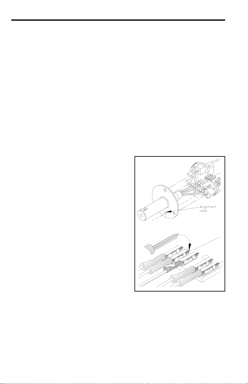
11. Insert the wire leads of the replacement
Heater assembly through the Heat
Dissipater. Align Heater assembly with
the Alignment Hole (on heater flange)
directly over the Heat Dissipater Screw.
12. Using needle nose pliers, carefully plug
the five (5) color coded wire leads of the
replacement Heater assembly into the
receptacles of the PCB Assembly.
Ensure that the leads are inserted as
shown with the flat surface of the metal
pins down against the PCB. Plug the T a n
leads into the jacks along either edge of
the pcb (#1 and #5; see PCB Cover
markings on illustration). Plug the bare
metal lead into the center jack (#3). Plug
the two (2) Blue leads into the two (2)
remaining jacks (#2 and #4).
13. Place the replacement Solder Shield on the bottom of the PCB Cover,
aligning the holes in the Solder Shield with the 2 holes on the cover . Press
the hole at the rear (small end) of the Solder Shield over the shoulder (with
hole) at the rear of the PCB Cover. This will hold the Solder Shield in
position on the cover.
14. Place the PCB Cover (with attached Solder Shield) back over the PCB
Assembly. Attach to the handpiece using the two (2) screws removed in
step #9.
2
Page 3

15. Reassemble the handpiece in the following order.
a) Replace the Handpiece (Bottom) removed in step #8.
b) Replace the two (2) Heat Dissipater Screws removed in step #7.
c) Replace the three (3) Heater assembly Screws removed in step # 6.
d) Replace the two (2) Handpiece Mounting Screws removed in step #5.
e) Replace the two (2) C Clips removed in step #4.
f) Replace the solder collection chamber and the end cap assembly
removed in step #3. Replace the tip.
16. Connect the handpiece to the power source. NOTE - A small amount of
smoke will be emitted for a short period of time when the heater is
initially powered up.
HEATER CONNECTIONS
Heater
Leads
Tan Lead
Tan Lead
Blue Lead
Blue Lead
Bare Lead
To
To
To
To
To
PCB
Jack #
1
5
2
4
3
3
Page 4

PACE Incorporated retains the right to make changes to specifications contained
herein at any time, without notice.
Contact your local authorized PACE Distributor or P ACE Incorporated to obtain the
latest specifications.
The following are registered trademarks and/or servicemarks of PACE Incorporated,
Laurel Maryland U.S.A. and may only be used to identify genuine P ACE products or
services:
Arm-Evac, Cir-Kit, ConducTweez, CRAFT, Flo-D-Sodr, Heat Wave,
HotSpot, LapFlo, MBT, Micro Portable, MicroChine, MiniChine,
Mini-Wave, PACE, Pacenter, Pik-Tip, PETS, Prep-Set, ResisTweez,
SensaTemp, Snap-Vac, Sodr-Pen, Sodr-X-Tractor, ST, StripTweez,
Thermo-Drive, ThermoFlo, ThermoJet, ThermoPart, ThermoPik,
ThermoTweez.
The following are trademarks and/or servicemarks of PACE Incorporated, Laurel
Maryland U.S.A. and may only be used to identify genuine P ACE products or
services:
Sodrtek, T oolnet.
Since 1958, PACE Incorporated has provided advanced
technology training in all aspects of hand soldering,
rework and repair.
© 1999 PACE Incorporated, Laurel MD. All rights reserved. Printed in the U.S.A.
4
 Loading...