

Page 1
ST 85 Systems
Operation & Maintenance Manual
Page 2

PACE Incorporated retains the right to make changes to specifications contained
herein at any time, without notice.
Contact your local authorized PACE Distributor or PACE Incorporated to
obtain the latest specifications.
The following are registered trademarks and/or servicemarks of PACE
Incorporated, Laurel Maryland U.S.A. and may only be used to identify
genuine PACE products or services:
Arm-Evac, Flo-D-Sodr , Mini-Wave, P ACE, SensaTemp, Snap-V ac, Sodrtek,
Sodr-X-T ractor, ThermoFlo, ThermoJet, ThermoTweez, T oolnet, Visifilter .
For any questions regarding this Operation & Maintenance Manual, contact your
local authorized P ACE distributor or contact PACE directly at the appropriate address
listed below.
P ACE USA 9893 Brewers Court
Laurel, Maryland 20723-1990
Tel.: (301) 490-9860
(888) 535-7223 (PACE)
Fax (301) 498-3252
PACE EUROPE Sherbourne House, Sherbourne Drive
Tilbrook, Milton Keynes
MK7 8HX
United Kingdom
Tel.: (44)1908 277666
Fax: (44)1908 277777
or
www.paceworldwide.com
© 2000 P ACE Incorporated, Laurel MD. All rights reserved. Printed in the U.S.A.
i
Page 3

MANUAL NUMBER 5050-0455
REV. C
SYSTEM QUICK START
The ST 85 system is very easy to operate and can be quickly
set up for use in standard desoldering/soldering operations.
T o begin operation of your new system quickly , perform
the "Set-Up" and "Quick Start - Basic Operation"
procedures detailed on pages 13-19 of this manual. A
shaded title bar on each of these pages highlight their location.
1
Page 4

Table of Contents
TITLE PAGE
General Information ................................................................................................. 4
Introduction ................................................................................................. 4
Specifications ............................................................................................... 4
Parts Identification ....................................................................................... 5
Safety ...................................................................................................................... 6
Safety Guidelines, English Language ........................................................... 6
Safety Guidelines, French Language ............................................................ 7
Safety Guidelines, German Language ........................................................... 8
Safety Guidelines, Italian Language ............................................................. 9
Safety Guidelines, Portuguese Language ....................................................10
Safety Guidelines, Spanish Language .........................................................11
Safety Guidelines, Swedish Language .........................................................12
Set-Up ....................................................................................................................13
Stacking.......................................................................................................13
Tip & Tool Stand ......................................................................................... 13
Air Supply Connection................................................................................ 14
Handpiece Vacuum/Pressure .......................................................................15
Handpiece Connection ................................................................................17
System Power Up ........................................................................................ 17
Heater Burn In ............................................................................................. 17
Quick Start - Basic Operation .................................................................................19
Introduction ................................................................................................ 19
Quick Start Procedure ..................................................................................19
Operation ...............................................................................................................20
Definitions...................................................................................................20
Password .....................................................................................................21
Auto Tip Temperature Compensation ......................................................... 21
LED Display - Normal Operation .................................................................22
LED Display - Temperature Adjust Mode....................................................23
Temperature Setback ...................................................................................24
Activation ..............................................................................................24
Operation ...............................................................................................24
Exiting Temperature Setback ..................................................................25
Auto Off Safety System...............................................................................25
Operation ...............................................................................................25
Exiting Auto Off ..................................................................................... 25
Quick Tour ...................................................................................................26
Factory Settings ..........................................................................................28
LED Display Accuracy ................................................................................28
2
Page 5

Table of Contents
TITLE PAGE
Set-Up Mode.......................................................................................................... 29
Introduction ................................................................................................ 29
Entering Set-Up Mode................................................................................. 29
Operation.....................................................................................................30
Password................................................................................................30
Temperature Scale ..................................................................................30
Temperature Limits .................................................................................31
Offset Constant ......................................................................................32
Temperature Setback ..............................................................................32
Auto Off................................................................................................. 33
Temperature Display Impedance ............................................................ 33
Exiting Set-Up Mode ..............................................................................33
Corrective Maintenance .........................................................................................34
LED Display Message Codes ......................................................................34
Power Source............................................................................................... 35
Handpieces..................................................................................................36
Packing List/Spare Parts......................................................................................... 37
Packing List ................................................................................................. 37
Spare Parts...................................................................................................37
Limited Warranty Registration Form.......................................................................38
TABLE PAGE
Table 1 Factory Settings ..................................................................................28
Table 2 LED Display Message Codes ..............................................................34
Table 3 Power Source Corrective Maintenance................................................35
Table 4 Heater Assembly Checkout Procedures ..............................................36
Table 5 Packing List .........................................................................................37
Table 6 Spare Parts ..........................................................................................37
3
Page 6

General Information
Introduction
Thank you for purchasing the PACE model ST 85 Digital Desoldering/Soldering System.
This manual will provide you with the information necessary to properly set up, operate
and maintain the ST 85 system.
The ST 85 systems are available in either the 115 VAC, or 230 VAC version which
incorporates a highly responsive SensaTemp (closed loop) control system providing up
to 80 Watts of total power to a single output channel. The 230 VAC version system
bears the CE Conformity Marking which assures the user that it conforms to all the
requirements of council directive EMC 89/336/EEC. The systems package the power
source with a selection of accessories and functional aids.
The 115 VAC version system conforms to all the requirements of FCC Emission Control
Standard, Title 47, Subpart B, Class A. This system has been tested and found to
comply with the limits for a Class A digital device, pursuant to part 15 of FCC rules.
These limits are designed to provide reasonable protection against harmful interference
when the equipment is operated in a commercial environment. This equipment
generates, uses, and can radiate radio frequency energy and, if not installed and used in
accordance with this manual, may cause harmful interference to radio communications.
Operation of this equipment in a residential area is likely to cause interference in which
case the user will be required to correct the interference at his own expense.
Specifications
System Power Source Power Requirements
ST 85 - Operates on 97-127 VAC, 50/60Hz, 90 Watts maximum
at 115 VAC, 60Hz
ST 85E - Operates on 197-253 VAC 50/60Hz, 80 Watts maximum
at 230 VAC, 50Hz
Shop Air Input Requirements:
Pressure - 5.48 Bar (80 p.s.i.) recommended
6.17 Bar (90 p.s.i.) maximum
Air Flow - 45.3 SLPM (1.6 SCFM) minimum
Temperature Specifications
Handpieces
Tip Temperature Range: 204 to 482°C (400 to 900°F) nominal.
Temperature Stability: ±1.1°C (±2°F) at idle from set tip temp.
NOTE - Actual minimum and maximum Operating Tip Temperatures may vary depending
on Handpiece, Tip Selection and application.
4
Page 7
General Information
EOS/ESD Specifications
The specifications shown below apply except on "Soft Ground Systems" which have
a 1 meg ohm current limiting resistance and a label placed on the power source front
panel referring to EN 100015-1.
Tip-To-Ground Resistance: Less than 2 ohms.
AC Leakage: Less than 2 millivolts RMS from 50Hz to 10MHz.
Transient Level: Less than 500mV peak, out to 100MHz.
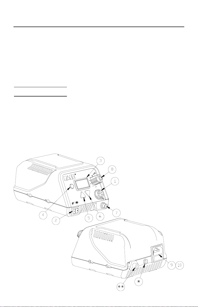
Parts Identification
• Power Receptacle
‚ Power Switch
ƒ LED Display
„ Program Key
… Scroll Up Key
†Scroll Down Key
‡Vacuum Port
ˆControllable Pressure Port
‰ AC Power Receptacle/Fuse Holder
Š Fuse
SS Air Fitting
S Earth Ground Re ceptacle
(230 VAC sytems only)
5
Page 8

Safety
Safety Guidelines - English Language
The following are safety precautions which personnel must understand and follow
when using or servicing PACE products.
1. POTENTIAL SHOCK HAZARD - Repair procedures on PACE
products should be performed by Qualified Service Personnel only.
Line voltage parts may be exposed when the equipment is disassembled.
Service personnel must avoid contact with these parts when
troubleshooting the product.
2. To prevent personnel injury, adhere to safety guidelines in accordance
with OSHA and other applicable safety standards.
3. SensaTemp handpiece heaters and installed tips are hot when the
handpiece is powered on. DO NOT touch either the heater or the tip.
Severe burns may result.
4. PACE Tip & Tool Stands and handpiece cubbies are designed
specifically for use with the associated handpiece and houses it in a
manner which protects the user from accidental burns. Always store the
handpiece in its holder. Be sure to place the handpiece in its holder after
use and allow to cool before storing.
5. Always use PACE systems in a well ventilated area. A fume extraction
system such as those available from PACE are highly recommended to
help protect personnel from solder flux fumes.
6. Exercise proper precautions when using chemicals (e.g., solder paste).
Refer to the Material Safety Data Sheet (MSDS) supplied with each
chemical and adhere to all safety precautions recommended by the
manufacturer.
6
Page 9

Sécurité
Directives de Sécurité, Française Langue
Les précautions suivantes, sont celles que le personnel doit comprendre et suivre
lorsqu'il utilise, effectue la maintenance ou se sert d'un produit PACE.
1. Danger potentiel de choc èlectrique - Les procédures de réparation sur
les produits PACE doivent être effectuées seulement par du personnel
qualifié. Des parties de l'équipement désassemblées peuvent être sous
tension. Le personnel de maintenance doit éviter tout contact avec ces
parties en réparant le produit.
2. Pour prévenir tout préjudice, le personnel adhère au guide de sécurité en
accord avec OSHA (équivalent à des normes françaises de sécurité) et
d'autres standards de sécurité applicable.
3. La mise sous tension des outils SensaTemp comporte des éléments
chauffants (buse). Ces derniers, gardent la chaleur même après la mise
hors tension pendant un certain temps. Ne pas toucher les parties
chaudes aux extrémités des outils. Des brûlures sévères peuvent en
résulter.
4. Les outils PACE et leurs pannes ainsi que le support sont dessinés de
manière spécifique afin de protéger l'utilisateur/opérateur de brûlures
accidentelles. Reposer toujours les outils après chaque utilisation dans
leurs étuis/supports afin de permettre leur refroidissement.
5. Utiliser toujours les stations Pace dans unlieu bien ventilé. Des
extracteurs de fumée Pace sont hautement recommandés pour protéger
votre personnel des vapeurs de soudure/flux.
6. Prenez les mesures nécessaires quand vous utilisez des produits (ex:
solder paste) chimiques. Reportez-vous au document (fiche technique/
sécurité) du fabricant fourni avec chaque produit. Respectez toutes les
procédures de sécurité recommandées par le constructeur.
7
Page 10

Sicherheit
Sicherheit Korrekturlinien, Deutsche Sprache
Die nachfolgenden Sicherheitsvorschriften sollten vom Bedien- un Servicepersonal
verstanden und befolgt werden.
1. Entladung spannungsfuehrender Teile - Reparaturen an PACE Produkten
sollten nur von qualifizierten Personal durchgefuehrt werden.
Spannungsfuehrende Teile koennen sich bei gezogenen Netzstecker
entladen. Servicepersonal muss den Kontakt dieser Teile vermeiden.
2. Um moegliche Gefahren fuer Personen auszuschliessen, muessen alle
Sicherheitsvorschriften in Uebereinstimmung mit OSHA und anderen
anwendbaren Sicherheitsstandards eingehalten werden.
3. Angeschlossene SensaTemp Heizelemente von Handwerkzeugen und
installierte Loetspitzen sind heiss wenn das System eingeschaltet ist oder
erst vor kurzer Zeit ausgeschaltet wurde. Heizelement und Loetspitze
nicht beruehren. Verbrennungsgefahr.
4. PACE Tip & Tool und andere Handwerkzeugablagen sind so konstruiert,
dass ein versehentliches Beruehren des dazugehoerendes
Handwerkzeuges vermieden wird. Bewahren Sie das Handwerkzeug nach
Gebrauch stets in der Ablage auf. Bevor das Handwerkzeug an einem
anderen Ort gelagert werden muss, lassen Sie es in der Werkzeugablage
vollstaendig abkuehlen.
5. Benutze PACE Systeme nur in gut beluefteten Raeumen. Ein
Loetrauchabsaugsystem, wie es z.B. von PACE erhaeltlich ist, hilft
Bedienpersonen von den Gefahren von Loetrauch zu schuetzen.
6. Wenn Chemikalien (z.B.: Lotpaste) verwendet werden, muessen alle die in
den Sicherheitsdatenblaettern des Herstellers ausgewiesenen
Sicherheitsvorschriften eingehalten werden.
8
Page 11

Sicurezza
Misure di Sicurezza, Italiana Lingua
Le seguenti instruzioni sono misure di sicurezza che il personale deve comprendere e
seguire quando utilizza o ripara I prodotti PACE.
1. EVENTUALI RISCHI DI SHOCK ELETTRICO- Si consiglia di far
eseguire le operazioni di riparazione dei prodotti PACE, da un servizio di
personale qualificato. Quando la stazione non é assemblata le parti
sottoposte alla tensione di linea potrebbero essere scoperte. Il personale
deve evitare il contatto con queste parti durante manutenzione del
prodotto.
2. Per evitare eventuali pericoli al personale, attenersi alle norme di sicurezza
previste dalla guida, in conformitá all’OSHA e agli altri Standard di Sicurezza
applicabili.
3. Le resistenze PACE Sensatemp e le punte installate sono calde quando la
stazione é accesa e per un periodo successivo allo spegnimento. Non
toccare la resistenza e la punta. Puó comportare gravi ustioni.
4. I supporti PACE sono specificamente costruiti insieme alla corrispondente
impugnatura e progettati per un uso che protegge gli utenti da ustioni
accidentali. Mettere sempre l’impugnatura nel propio supporto dopo
l’utilizzo e lasciarla raffredare prima di riporla.
5. Utilizzare sempre I stazioni PACE in una zona be aerata per proteggere il
personale dai fumi. É fortemente raccomandato un sistema di aspirazione
(dei fumi) come quello disposta dalla PACE.
6. Usare precauzioni quando si utilizzano sotanze chimiche (es. Pasta di
stagno). Fare riferimento al Material Safety Data Sheet (MSDS) fornita con
ogni sostanza chimica e seguire tutte le misure di sicurezza raccomandate
dal fabbricante.
9
Page 12

Segurança
Guidelines de Segurança, Portuguese Lingua
Segeum-se precauções de segurança que os operadores devem compreender e seguir
ao utilizar ou reparar produtos PACE.
1. Perigo de choque eléctrico - Os procedimentos de reparação em
produtos PACE, devem ser apenas efectuados por pessoal qualificado.
Linhas de alimentação podem ficar expostas ao desmontar o
equipamento. Pessoal de reparação deve evitar o contacto com essas
partes ao reparar o produto.
2. Para evitar danos pessoais, siga as normas de segurança OSHA ou outras
normas aplicáveis.
3. Resistencias de aquecimento dos ferros e as pontas instaladas estão
quentesquando o ferro está alimentado, e mesmo durante algum tempo
após ser desligado. NUNCA TOCAR nem na resistencia de
aquecimento nem na ponta. Pode resultar em queimaduras severas.
4. Os suportes para pontas e ferros da PACE, foram concebidos para uso
especifico, e para proteger o operador de queimaduras acidentais.
Coloque sempre os ferros nos respectivos suportes. Tenha a certeza de
colocar sempre o ferro no respectivo suporte após cada utilização e deixeo arrefecer antes de o guardar.
5. Utilize sempre os sistemas da PACE em locais bem ventilados. Um Sistema de
extracção de fumos, como os Sistemas disponiveis na PACE, são altamente
recomendados para a protecção dos utilizadores contra os fumos produzidos pela
solda e fluxo.
6. Tenha precauções apropriadas ao utilizar produtos quimicos (ex. pasta de soldar).
Lêr sempre atentamente os normas de segurança fornecidas com cada produto
químico e siga sempre todas as precauções de segurança recomendadas pelo
fabricante.
10
Page 13

Seguridad
Guias de Consulta de Seguridad, Espãnol Lenguaje
Lo siguiente es precauciones de seguridad que el personal debe entender y debe
seguir al usar o reparar productos de PACE.
1. RIESGO de SHOCK POTENCIAL - Los procedimientos de la Reparación en
productos de PACE sólo deben ser realizados por Personal de Servicio
Calificado. Pueden exponerse partes de voltaje de línea cuando el equipo se
desmonta. El personal de servicio debe evitar contacto con estas partes al
arreglar el producto.
2. Para prevenir lesión del personal, adhiera a las reglas de seguridad de
acuerdo con OSHA y otras normas de seguridad aplicables.
3. Las herramientas SensaTemp tienen sus calentadores y las puntas
instaladas calientes cuando la herramienta esta encendida y por un
periodo de tiempo después de apagar el equipo. No toque el calentador o
la punta. Las quemaduras severas pueden resultar.
4. El Soporte de punta y Herramienta PACE se diseñan específicamente para
el uso con las herramientas asociadas y las almacena de una manera que
protege al usuario de las quemaduras accidentales. Siempre guarde la
herramienta en su soporte. Esté seguro de poner la herramienta en su
soporte después del uso y permita que la herramienta enfríe antes de
guardar.
5. Siempre use sistemas de PACE en una área bien ventilada. Un sistema de
extraccíon de humo como esos disponibles de PACE se recomiendan para
ayudar a protejer al personal contra los humos de flujo de soldadura.
6. Ejercicie las precauciones apropiadas al usar químicos (ej., pasta de la soldadura).
Refiérase a la Hoja de Datos de Seguridad de Material (MSDS) proporcionadó con
cada químico y adhiere a todas las precauciones de seguridad recomendadas por
el fabricante.
11
Page 14

Säkerhetsföreskrifter
Säkerhetsföreskrifter, Svenska
Följande säkerhetsföreskrifter måste förstås och följas av personal som använder
eller utför service på PACE produkter.
1. RISK FÖR STRÖMSTÖT - Service / Reparation av PACE produkter
får endast utföras av aktoriserad service personal. Strömförande delar
kan kommas åt när produkten är isärplockad. Iaktag aksamhet när
felsökning görs för att undvika strömstötar.
2. För att undvika personskada rekommenderas att OSHA eller andra
liknande arbetssäkerhets standarder följs.
3. SensaTemp verktygselement och installerade spetsar är heta när
strömmen är påslagen och en tid efter att strömmen slagits av. RÖR EJ
element eller spets. Risk för brännskador!
4. PACE Spets och Verktygshållare är speciellt utformade för att passa
PACE respektive verktyg så att risken för brännskador kan undvikas. När
verktyget ej används bör det alltid förvaras i sin hållare.
5. Tillse att ventilationen är god där PACE System används. Ett
lödröksutsug system som t.ex. PACE tillhandahåller rekommenderas för
att skydda användaren för giftig lödrök.
6. Tillse att gällande säkerhetsföreskrifter följs vid användning av
kemikalier, t.ex. lodpasta.Se säkerhetsdatabladen som medföljer
kemikalierna och följ de rekommenderade säkerhetsföreskrifterna från
respektive tillverkare.
12
Page 15
Set-Up
Set-up
Set up the ST 85 system using the following steps and associated drawings.
1. Store the shipping container(s) in a
convenient location. Reuse of these
containers will prevent damage if you store
or ship the system.
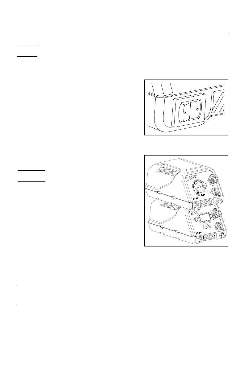
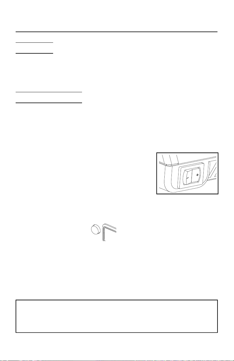
2. Place the Power Switch in the “OFF” or “0”
position.
Stacking
ST 25, 45, 65 & 85 systems can be stacked one on
top of the other (up to 3 units high). Ensure that
the power sources are positioned as shown with
the recessed area in the bottom of the top power
source placed over the raised portion on top of the
bottom power source.
13
Page 16
Set-Up
Tip & Tool Stand
If you have purchased a system with a handpiece, set up the Tip & Tool Stand in the
following manner. If you have purchased another SensaTemp handpiece, use the
instructions enclosed with the handpiece and associated Tip & Tool Stand.
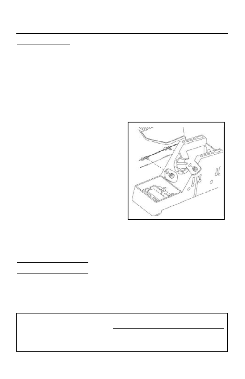
1. To attach the stand to the power source, use the following procedure.
a) Insert the 2 Mounting Screws
(head first) into the 2 power
source mounting slots shown.
Slide the screws toward rear of
power source.
b) Place the Tip & Tool Stand
beside the power source.
Insert ends of the 2 Mounting
Screws into the 2 Tip & Tool
Stand mounting holes shown.
c) Install a Thumb Nut onto the
end of each Mounting Screw.
Tighten Thumb Nuts to secure
the stand in position.
2. Place the handpiece into its Tip &
Tool Stand.
Air Supply Connection
The ST 85 system utilizes an integral air venturi system to provide air pressure and
vacuum for any connected PACE SensaTemp air handpiece. Your in-house air supply
(regulated to 5.48 Bar (80 P.S.I.); see "Specifications") must be connected to the
system power source.
CAUTION
The system must be connected to a clean, dry, and filtered air supply regulated
to 5.48 Bar (80 P.S.I.); see "Specifications". Connection to a contaminated air
supply or one with pressure in excess of 6.16 Bar (90 p.s.i. may cause damage
to the power source.
14
Page 17
Set-Up
1. Attach a length of Small, Flexible Air Hose (not supplied) to the Air Hose Fitting on
the rear of the PACE power source using the following procedure.
PACE does not recommend the attachment of quick connect air hose
fittings to the power source. The weight of the standard large air hose
lines will affect the stability of the system and would require a larger
bench space.
a) 230 VAC Systems only: A metric adapter fitting (PACE part number
1259-0081) is included for use with 230 VAC systems.
NOTE
DO NOT overtighten connections. Damage to
the system could occur if excessive torque is
applied to the Air Hose Fitting, metric adapter
or Connector.
b) Install the Connector (with Small,
Flexible Air Hose) onto the Air
Hose Fitting (or metric adapter)
finger tight. Using an appropriate
wrench, tighten the Connector an
additional 1/4 turn. DO NOT
overtighten.
2. Connect the free end of the small,
flexible air line to your air supply
using the appropriate fittings.
Handpiece Vacuum/Pressure
To set up your Sodr-X-Tractor air hose connection, perform the following steps:
1.Air Hose To Handpiece Connection
a) Attach one end of a 137cm (54 inch) length of air hose to the metal tube in the
back of the handpiece.
b) If you have a PACE system incorporating only one handpiece, attach the air
hose to the power cable using the supplied Hose Clamps. Space them evenly
along the length of the power cable starting at a point 6 inches from the ends
of the handpiece.
c) If you have a PACE system incorporating 2 or more air handpieces, you may
wish to leave the air hose assembly unattached to allow a quick change to
any air handpiece being used.
15
Page 18
Set-Up
2. Prepare a VisiFilter in the following manner:
a) Connect a 1 inch (2.5cm) length of clear pvc air
hose to the FLOW OUT side of the VisiFilter;
push and turn the hose onto the VisiFilter
nipple to seat.
b) Insert the ribbed end of a male quick connect
hose mount fitting (P/N 1259-0087) into the
free end of the 1 inch (2.5cm) length of air hose
connected to the FLOW OUT side of the
VisiFilter.
c) Connect the free end of the 137cm (54 inch)
length of air hose to the FLOW IN side of the
VisiFilter.
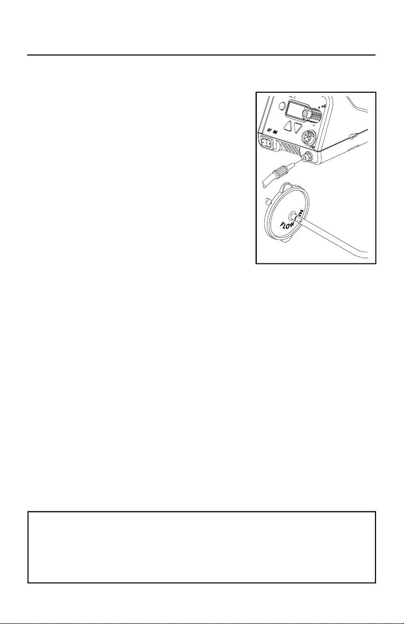
d) Insert the end of the quick connect hose
mount fitting (on VisiFilter FLOW OUT
side) into the power source Vacuum Port.
3. When using air pressure, and/or utilizing multiple air handpieces,
PACE recommends the use of the following set up procedure which
utilizes additional quick connect hose mount fittings. An assortment
of quick connect air fittings are supplied with each additional air
handpiece.
a) Disconnect the 137cm (54 inch) length of air hose from the FLOW
IN side of the VisiFilter assembly. Insert the ribbed end of a male
quick connect hose mount fitting (P/N 1259-0087) into the free
end of this air hose.
b) Connect the free end of a 1 inch (2.5cm) length of air hose with
an installed female quick connect hose mount fitting (P/N 1259-
0086) to the FLOW IN side of the VisiFilter Assembly.
c) The 137cm (54 inch) length of air hose can now be easily moved
between the VisiFilter Assembly and the Controllable Pressure Port.
The VisiFilter assembly remains connected to the Vacuum Port.
4. Additional fittings may also be added to the hose connection at the
rear of each air handpiece to ease changing of handpieces.
NOTE
When removing any air hose, turn and pull. Do not attempt to pull hose directly off.
Damage to or breakage of fitting or VisiFilter may occur. Use your Sodr-X-Tractor with
a clean VisiFilter element. Otherwise a deterioration in performance or damage to the unit
may occur.
16
Page 19
Set-Up
Handpiece Connection
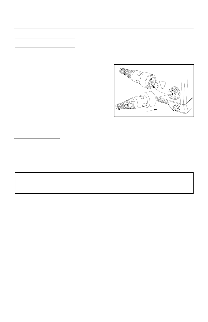
Connect the handpiece connector plug into the Power Receptacle in the following
manner.
1. Align guide on connector with slot on
power receptacle.
2. Insert connector into power receptacle.
3. Turn the connector housing clockwise
to lock in place.
System Power Up
1. Insert the female end of the power cord into the AC Power Receptacle at
the rear panel of the power source.
2. Plug the prong end (male end) of the power cord into a 3 wire grounded
AC supply receptacle. The system is now ready for operation.
CAUTION
To ensure operator safety, the AC supply receptacle must be checked for proper
grounding before initial operation.
3. Read this manual and all other included manuals thoroughly before
operating the system.
17
Page 20
Set-Up
Heater Burn In
To ensure optimum performance and long life, new TJ-70 handpieces must undergo a
burn in procedure. A Red tag is attached to each handpiece and with replacement
heater assemblies which describes the proper procedure. The ST 85 system
however, has a Burn In feature which, when activated will burn in the TJ-70 heater in
a similar manner as is described on the tag. Use this feature when setting up a new
ST 85 system or when replacing a TJ-70 handpiece heater assembly.
NOTE
Ensure that the system is placed in a well-ventilated area. Smoke will be emitted from
the heater assembly during the burn in cycle.
Use the following instructions to perform the Heater Burn In procedure.
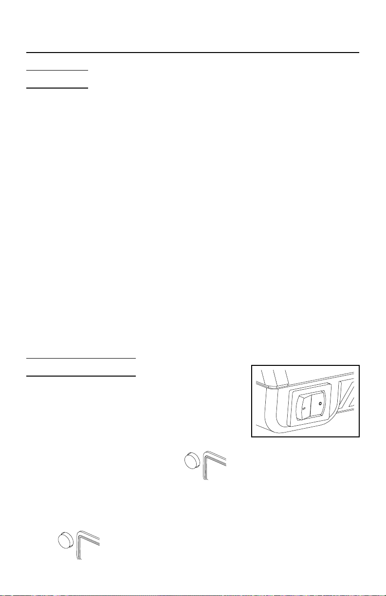
1. Place the Power Switch in the “OFF” (0) position.
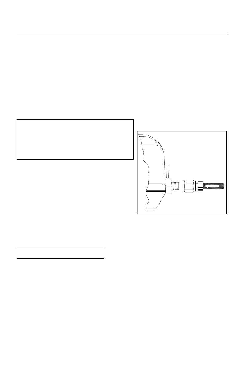
2. Ensure that the handpiece is connected to the system power source.
Some handpieces heater assemblies are shipped with
a plastic cap installed on the end of the heater
assembly. If this cap is present, remove the cap and
discard. The cap is used for shipping purposes only.
3. Press and hold the Program ( ) and
Scroll Up (▲) keys together.
4. Place Power Switch in “ON” (I) position.
5. Release the Program ( ) and Scroll Up
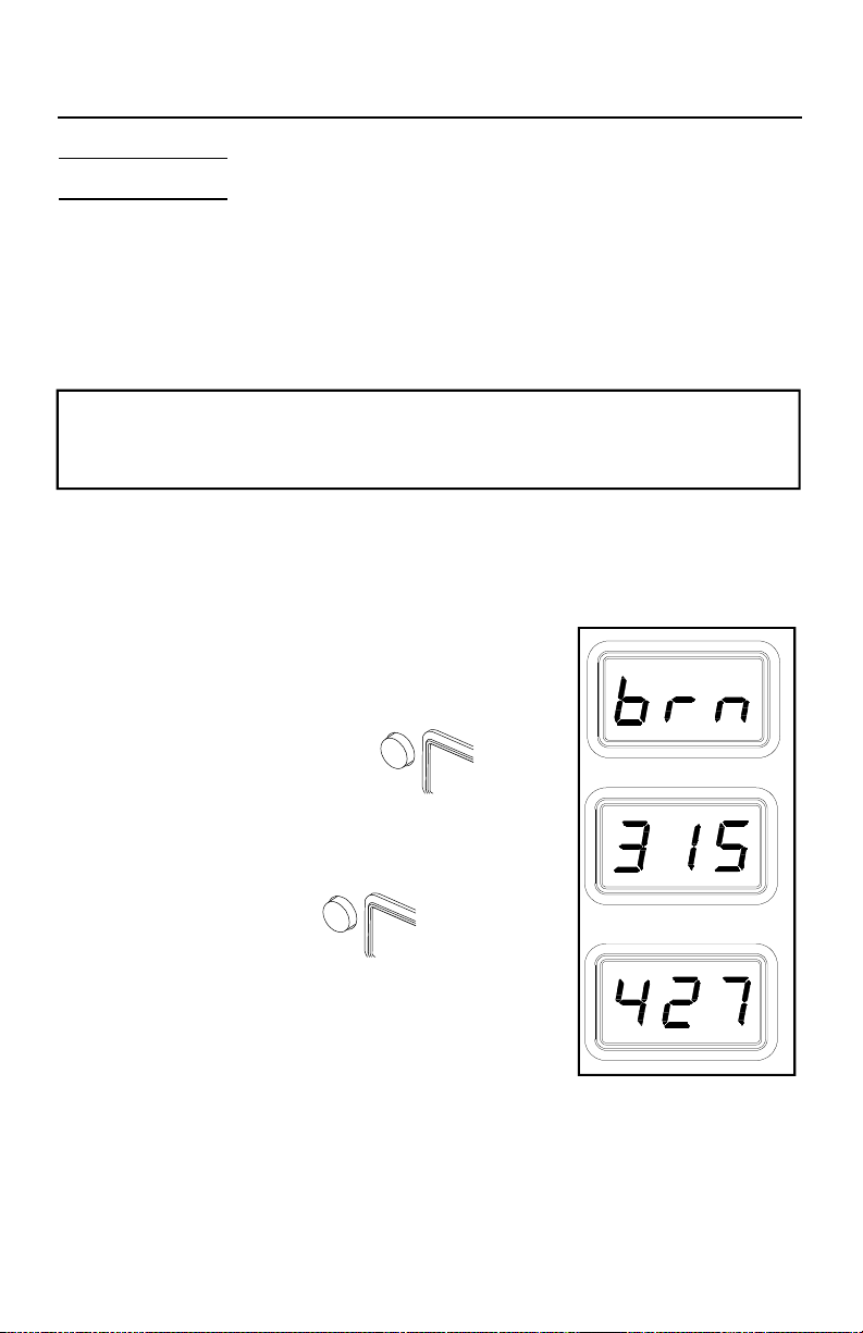
(▲) keys. The Display will read “brn”.
6. Press the Scroll Up (▲) Key to enter the Burn In
Mode. The handpiece heater will begin to heat up
with the temperature displayed (in °C or °F). The
heater temperature will stabilize at 315°C (or 600 °F) and remain at that
temperature for 10 minutes.
7. At the conclusion of the 10 minute period, the heater temperature will
increase to 427°C (or 800°F) and remain at that temperature for 15 minutes.
18
Page 21

Set-Up
8.At the conclusion of the 15 minute time period, power is removed from the
heater. The Display will read “End”. Press and release the Scroll Up Key
(▲) to exit Heater Burn In and return the to normal operation.
NOTE
The microprocessor circuitry within the unit monitors the system to ensure proper
results. If any abnormalities are encountered, the Burn In cycle will be interrupted and
an error message displayed. If this situation should occur, turn the system off and
perform the procedure again. If the cycle is interrupted a second time, refer to Table
IV and check for handpiece malfunction. If a second handpiece is available, perform
the procedure using that handpiece.
19
Page 22
Quick Start - Basic Operation
Introduction
The ST 85 system is very easy to operate. As received from the factory, the system
can be quickly set up for use in standard desoldering/soldering operations. Simply
perform the following Quick Start Procedure to begin system operation.
Quick Start Procedure
1. Ensure that the Set-Up procedure has been performed; including the
Heater Burn In procedure. Check for the following:
a) Handpiece connections (connector plug and air hose) to the power
source.
b) Proper tip installed in handpiece.
c) Power cord connection between house AC
supply receptacle and the power source.
d) House air supply connection to power supply.
2. Turn the Power Switch “On” (“I”).
3. Press the Scroll Up (▲) Key to enter the Temperature Adjust Mode.
4. Press the Scroll Up (▲) Key to increase the desired Tip Temperature.
Press the Scroll Down (▼) Key to decrease the desired Tip Temperature.
5. Press the Program Key ( ). The system will now return to
normal operation.
6. Observe the Digital Readout as the temperature stabilizes at the desired
Set Tip Temperature.
7. If you have a Sodr-X-Tractor or other PACE air handpiece connected to
your system, press and hold the Vacuum Switch to check for proper
operation. You will hear a clicking noise as the air is turned on in the
system. An audible sound of air movement will be present. Release the
Vacuum Switch.
NOTE
Read the “Operation” and “Set-Up Mode” sections of this manual to utilize the full
capabilities of the system. This is especially important when using large soldering
tips or other SensaTemp handpieces.
20
Page 23

Operation
IMPORTANT
PACE recommends that you not read the “Set-Up Mode” section until after you feel
comfortable with system operation. Please read the following “Operation" section
thoroughly before changing the system settings.
Definitions
Please read and become familiar with the definitions of each of the following terms
which are used repeatedly in the following operational procedures.
AUTO OFF - Safety feature which turns power off (10-90 minutes, settable in 10
minute increments) after the system has entered Temperature Setback.
NORMAL OPERATION - Normal operating mode of the system in which the
Operating Tip Temperature is displayed.
OPERATING TIP TEMPERATURE - The true tip temperature at which the handpiece
tip operates at any given time.
SET TIP TEMPERATURE - The operator selected idle tip temperature entered into
the system memory.
SET-UP MODE - Mode of operation in which the operator can quickly and easily
adjust the system parameters (e.g., temperature limits, password, setback time).
TEMPERATURE ADJUST MODE - Mode of operation in which the operator can
quickly and easily adjust the Set Tip Temperature.
TEMPERATURE DISPLA Y IMPEDANCE (TDI) MODE - Stabilizes the tip
temperature shown on the LED Display by ignoring minor temperature fluctuations.
Displayed changes in temperature are delayed (impeded) for two seconds when a
load is applied to the tip. Two seconds after the load is removed, the displayed
temperature will begin rising to set temperature. Particularly useful in a production
environment for monitoring of set temperatures, since under most production
circumstances the temperature will not deviate.
TEMPERATURE SETBACK - System feature which, when enabled, will
independently set back the Set Tip Temperature to 177°C (350°F) after a user selected
period of handpiece inactivity (10 to 90 minutes, settable in 10 minute increments).
This feature is enabled (or disabled) in the Set-Up Mode.
TIP OFFSET CONSTANT - Specific value for a given handpiece/tip combination
upon which the system automatically calculates the correct Tip Temperature Offset at
any entered Set Tip Temperature. This value is the temperature loss (Tip Temperature
Offset) at 371°C (700°F) and is set in the Set-Up Mode. A value of 0-115°C (0-240°F)
may be entered in the Set-Up Mode.
21
Page 24

Operation
TIP TEMPERATURE OFFSET - Difference in value between the temperature
measured by the temperature sensor (at the heater) and the true temperature of the tip
at a given Set Tip Temperature.
NOTE
As with any system, Set and Operating Tip Temperatures are only exactly equal when
the handpiece is idling (unloaded at equilibrium). During use, (i.e., under load) the
Operating Tip Temperature will usually be lower.
Password
The Password feature of the ST 85 system, when activated, will prevent
unauthorized alteration of stored system temperature parameters and feature settings
(refer to Table I, “Factory Settings”). If a Password has been installed, the LED
Display will display an instruction to enter the Password (a 5 key sequence of the
keys on the system front panel) when a setting change is attempted.
Once the correct Password has been entered, the operator can proceed to make the
desired setting changes. To reactivate the Password protection, simply turn the
system Power Switch off and then back on. The system is now in normal operation.
Refer to the “Set-Up Mode” section of this manual for instructions on entering,
changing or removing a Password.
Auto Tip Temperature Compensation
Differences between the temperature settings and true tip temperatures are negligible
when using Thru-Hole, single point desoldering tips. With any heating system
however, True Tip Temperatures can differ greatly from temperature settings when
using larger SMT soldering tips. This difference is called Tip Temperature Offset.
The ST 85 Auto Tip Temperature Compensation feature lets you set and display true
tip temperatures regardless of size and type of tip or handpiece. PACE recommends
the use of the Tip & Temperature Selection System booklet (PACE P/N 5050-
0251) as a guide to accurately set and maintain a true tip temperature for any size
and type of SMT tip. The booklet contains a listing of PACE tip information
including the Tip Offset Constant (for each tip) which must be stored in system
memory to ensure tip temperature accuracy. Refer to the “Set-Up Mode” section
of this manual for instructions on using this feature.
22
Page 25
Operation
The ST 85 system is very easy to adjust and operate. The following instructions
detail system features and operation of the system. Also included is a "Quick Tour"
of system operation.
Information regarding changing of system options (e.g., T emperature Setback time,
Auto Off) is contained in the "Set-Up Mode" portion of this manual.
LED Display, Normal Operation
The LED Display provides a 3 digit display of temperature information. The LED
Display will show:
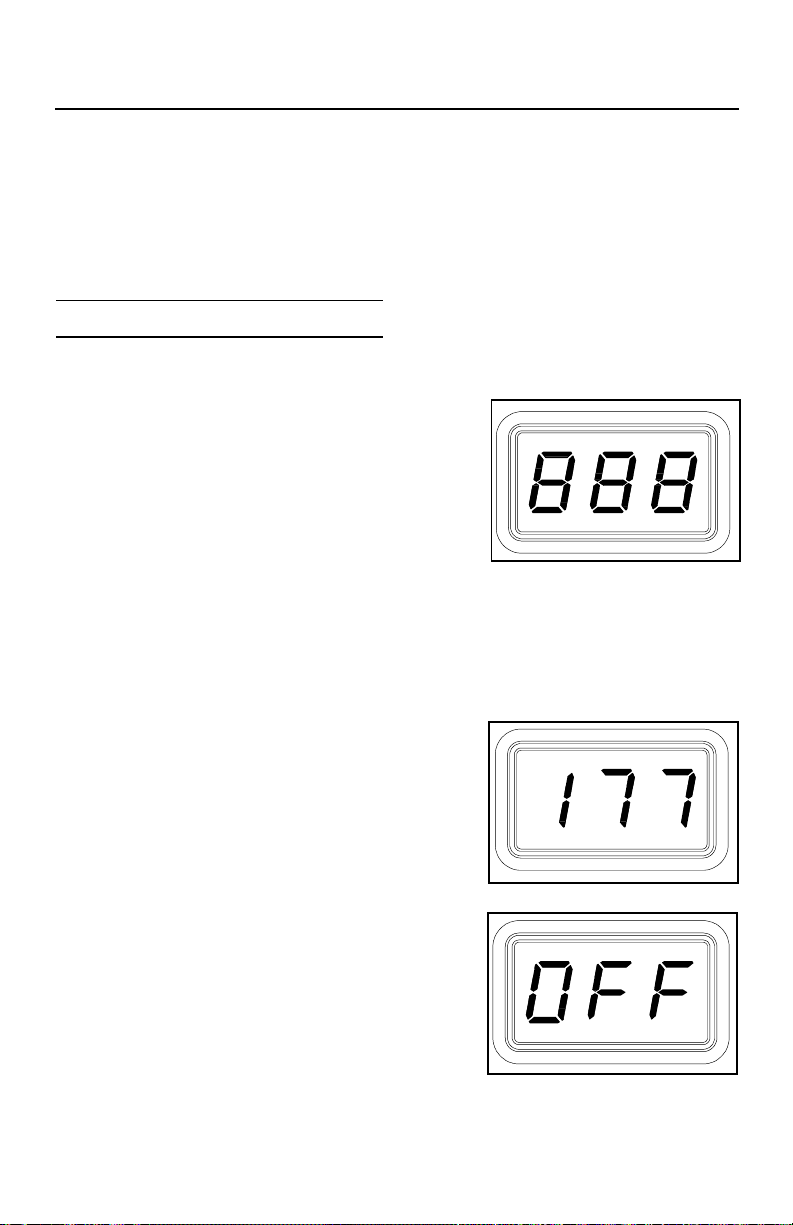
1 . A display of "888" on initial power up to
ensure that all LEDs on the display are
working.
2 . A display of the the software version of the installed microprocessor (e.g.,
"1-1") for 2 seconds on initial power up after the "888" is displayed.
3. Actual tip temperature of the connected handpiece during normal operation.
4 The tip temperature displayed will flash when the system is in Temperature
Setback.
5 . The displayed temperature will decrease and
stabilize at 177°C (350°F) when the system is
in T emperature Setback.
6 . "OFF" when the Set Tip Temperature has
been set to Off (below minimum set tip
temperature). Refer to the "Set-Up Mode"
portion of this manual.
7 . "OFF" plus the LED Display will be flashing
when the unit has entered Auto Off. Refer to
the "Set-Up Mode" portion of this manual.
23
Page 26

Operation
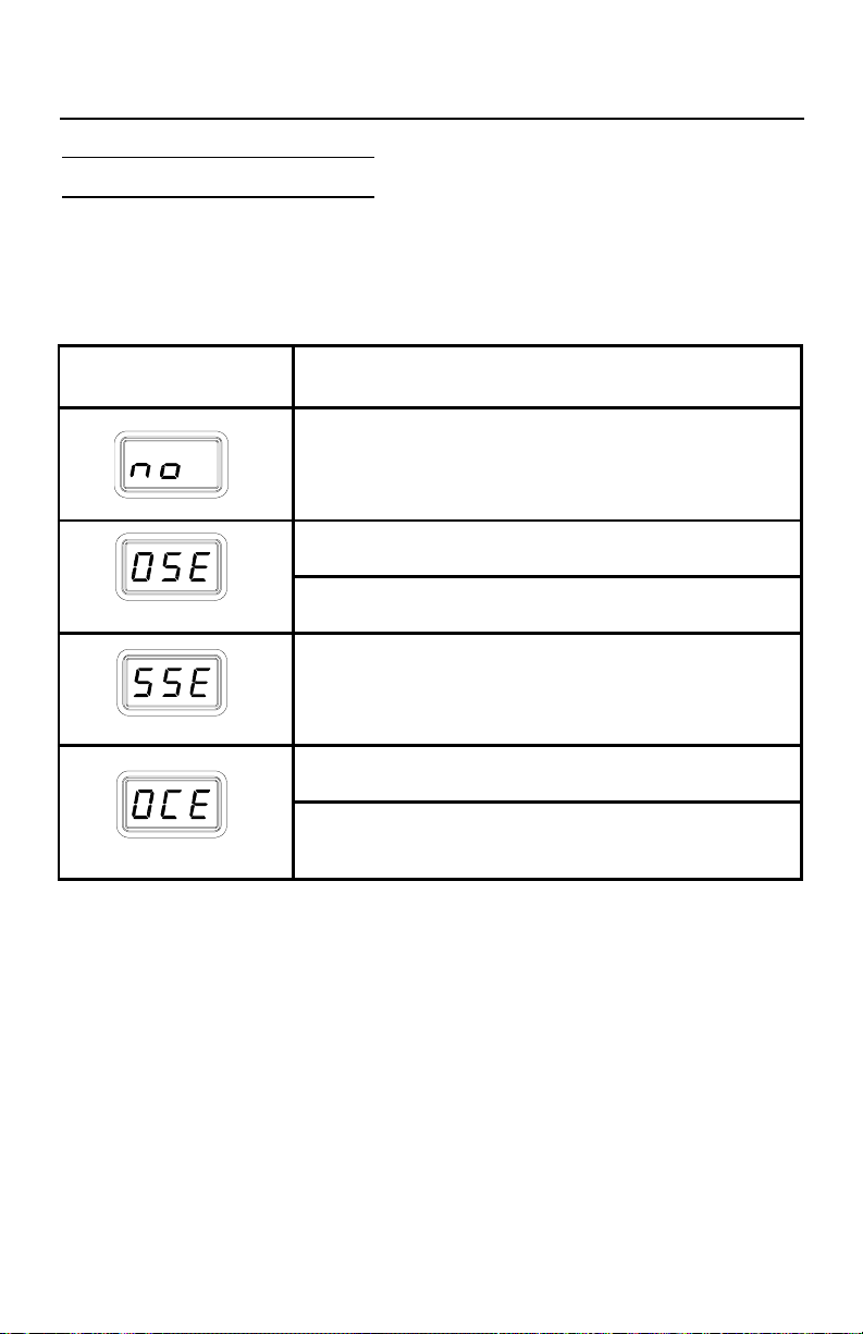
8 Error messages ("OSE", "SSE" or "OCE") if a
system fault is detected. Refer to the
"Corrective Maintenance" portion of this
manual.
LED Display, Temperature Adjust Mode
The LED Display will show the following when adjusting the desired Set Tip
T emperature.
1 . The Set T ip Temperature.
2 . "HiL" (High Temperature Limit) when
adjusting the set tip temperature and the
maximum allowable temperature is exceeded.
Refer to the "Set-Up Mode" portion of this
manual.
3 . "OFF" (Low Temperature Limit) when
adjusting the set tip temperature and the
minimum allowable temperature is exceeded.
Refer to the "Set-Up Mode" portion of this
manual.
4 . "EP0" will be displayed if a Set Tip
T emperature adjustment is attempted and a
Password has been stored in system memory.
As the 5 key Password is entered, the zero will
increase by one as each key entry is made.
Upon entry of the fifth password key, the
display will change to the Set Tip Temperature
if the entered Password matches the stored
Password.
5. "no" will be displayed if the entered password
does not match the stored Password.
24
Page 27

Operation
Temperature Setback
T o preserve tip life and save ener gy, the ST 85 system can be programmed to
automatically set back its Tip T emperature to 177°C (350°F) after a selected period of
handpiece inactivity (adjustable 10-90 minutes in Set-Up Mode). As received from
the factory, this feature is enabled. Refer to the “Set-Up Mode” section of this
manual to disable or adjust the time-out period of this feature. The operator can also
force the system into Temperature Setback.
Activation
There are two ways in which the system will activate the T emperature Setback feature.
1. Automatic Activation - The system memory can be programmed so that
the system will automatically activate T emperature Setback after a
selected period (10-90 minutes) of handpiece inactivity. See the “Set-Up
Mode” section for details on programming this feature.
2. Manual Activation - The operator can manually force the system to place
the system in T emperature Setback by performing the following
procedure.
a) Press and hold the Scroll Down (t) Key .
b) Press the Scroll Up (s) Key.
c) Release both keys.
Operation
T emperature Setback is indicated by the following.
1 . The LED display will be flashing.
2 . The Operating Temperature will stabilize at 177°C (350°F).
25
Page 28

Operation
Exiting Temperature Setback
Listed below are 3 different ways to exit T emperature Setback.
1 . Press and release either Scroll Key (s or t). This is the preferred
method.
2. Wipe the hot handpiece tip on a wet sponge to lower the tip temperature.
3 . Method “1” is preferred but you can turn the Power Switch “OFF” ("0")
and then back “ON” ("I").
Set Tip Temperature and Tip Offset Constant values will be simultaneously restored.
Observe the LED Display as the Operating Tip Temperature stabilizes at the Set Tip
T emperature. For optimum performance, do not attempt to use the attached
handpiece until the Set Tip Temperature is achieved.
Auto Off Safety System
When enabled, the Auto Off safety system of the ST 85 system removes power 10-90
minutes (enabled/disabled and adjustable in Set-Up Mode) after entering Temperature
Setback.
Operation
When the system has entered Temperature SetBack, an Auto Off timer within the
system circuitry will start running (if Auto Off is turned on in Set-Up Mode):
1. If any key is pressed during the selected time out period, the Auto Off
timer is reset. The system will return to normal operation.
2 . At the end of the time out period, the system will enter Auto Off. Power is
removed, the LED Display will show “OFF ” and the display will be
flashing.
Exiting Auto Off
Auto Off can be exited; returning to normal operation by:
1 . Pressing and releasing a Key (either of the 3 keys).
OR
2 . By turning the Power Switch OFF (“0”) and then back ON (“I”).
26
Page 29

Operation
Quick Tour
1. Ensure that the Set-Up procedure has been performed; including the
Heater Burn In procedure. Check for the following:
a) Handpiece connection to the power source.
b) Proper tip installed in handpiece.
c) Power cord connection between house AC supply receptacle and the
power source.
2 . Turn the Power Switch “On” (“I”).
3 . Press the Scroll Up (s) Key. The Set Temperature is now displayed. If no
other Key is pressed within 5 seconds, the system will revert to normal
operation. Allow time for the system to change back.
4 . Press the Scroll Up (s) Key . The Set Temperature is now displayed;
immediately perform step 5.
5 . Adjust the Set Temperature in the following manner:
a) Press and release the Scroll Up (s) Key to increase Tip Temperature in
increments. Press and release the Scroll Down (t) Key to decrease
Tip Temperature. Observe the display as the Set Temperature
increases in increments of 1°.
NOTE
If a Password has been previously programmed into the system, "EP0" will be appear
on the LED Display at this point. When this message appears, the operator must enter
the correct 5 key Password before adjusting the temperature. Refer to "Password"
in the "Operation" portion of this manual.
b) Adjust the temperature by pressing and holding Scroll Up (s) Key.
Observe the display as the Set Temperature increases first in
increments of 1° and then in increments of 10°. Release the key.
c) Using the Scroll Keys, adjust the temperature to any standard
operating temperature used by your company.
NOTE
The Set T emperature can only be within the set temperature limits. If a limit (upper or
lower) is reached, the lower limit would display “OFF”; the upper limit would not allow
the Set T emperature to exceed that limit. Temperature limits can be adjusted in the SetUp Mode.
27
Page 30

Operation
6 . Press the Program Key ( ). The system will now return to
normal operation.
7 . Observe the Digital Readout as the temperature stabilizes at the desired
Set Tip T emperature
8 . Manually force the system into Temperature Setback in the following
manner:
a) Press and hold the Scroll Down (t) Key and the Scroll Up (s) Key.
b) Release both keys.
9 . The system is now in Temperature Setback. Observe the flashing of the
LED Display and the decreasing of the tip temperature. Allow time for the
temperature to stabilize at 177°C (350°F).
NOTE
If Auto Off has been enabled (turned on in Set-Up Mode), the system will enter Auto Off
(temperature Off and LED Display flashing "Off") after the preset time of handpiece
inactivity . Auto Of f can be exited by pressing any key.
10. Manually force the system out of Temperature Setback in either of the
following manners:
a) Press and release a Key (either of the 3 keys). This is the preferred
method.
b) Wipe the hot handpiece tip on a wet sponge to lower the tip
temperature.
c) Turn the Power Switch Off ("0") and then back on ("I").
11. The system is now in normal operation. Observe the LED Display as the
tip temperature increases to the Set T emperature. Allow time for the
temperature to stabilize at the Set T emperature.
NOTE
Read the “Operation” and “Set-Up Mode” sections of this manual to utilize the full
capabilities of the system. This is especially important when using large soldering
tips or other SensaTemp handpieces.
12. If you have a Sodr-X-Tractor or other PACE air handpiece connected to
your system, press and hold the Vacuum Switch. Y ou will hear a clicking
noise as the air is turned on in the system. An audible sound of air
movement will be present. Release the V acuum Switch.
28
Page 31

Operation
FACTORY SETTINGS
The ST 85 system comes equipped with a number of features which may be adjusted,
enabled or disabled as desired by the user. Listed below are the features and factory
settings of each. To change and/or learn about any of these features, refer to the
applicable part of the “Set-Up Mode” portion of this manual.
FEATURE
Password None Entered
Default Temperature Scale (°C/°F)
"HI" (upper) Temperature Limit 482°C (900°F)
"LO" (lower) Temperature Limit 204°C (400°F)
Set Temperature "OFF"
Tip Offset Constant "0"
Temperature Setback Enabled
Setback Time 30 Minutes
Auto Off Enabled
Time To Auto Off 30 Minutes
FACTORY
SETTING
°F for 115V
Systems
°C for 230V
Systems
Table 1. Factory Settings
LED Display Accuracy
No adjustments are necessary to maintain the accuracy of the system.
29
Page 32
Set-Up Mode
Introduction
The menu driven LED Display of the ST 85 system in the Set-Up Mode allows you to
easily customize your system. No calibration adjustments are necessary to maintain
the accuracy of the system.
In Set-Up Mode, you can:
1 . Enter , remove or change a Password.
2 . Set the Default Temperature scale to °F or °C as desired.
3 . Change the Upper and Lower T emperature limits.
4 . Enter a Temperature Offset Constant (Auto Tip T emperature
Compensation).
5 . Enable or disable the Temperature Setback feature and adjust the time-
out period (if enabled).
6 . Enable or disable the Auto Off feature and adjust the time-out period (if
enabled).
7 . Enable or disable the A verage Temperature feature.
The following instructions should be performed to familiarize the operator with the
system.
Entering Set-Up Mode
1 . Place Power Switch in the “OFF” (“0”) position.
2 . Press and hold the Program Key ( )
3 . Place Power Switch in the "ON" (“1”) position. Release the Program Key
( ).
30
Page 33
Set-Up Mode
Operation
Password
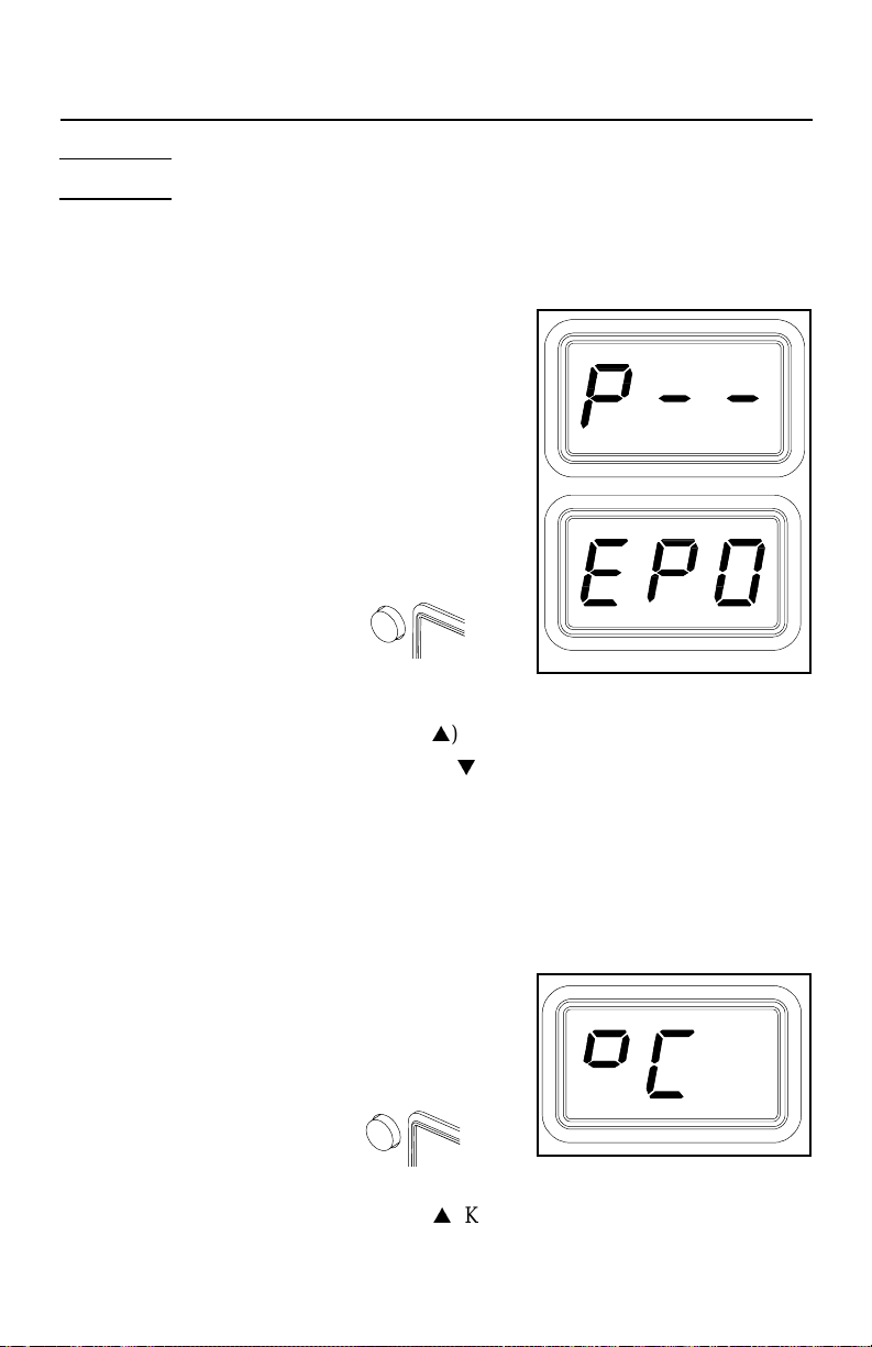
4 . The LED Display will display the version of the microprocessor and
change to read “P--” or "EP0".
5. If the display reads "EP0", a Password has
been stored in system memory. Enter the 5 key
sequence Password. If the Password entered
is incorrect, "no" appears on the display and
the system then returns to normal operation.
If this occurs, repeat steps 1 through 5 and
enter the correct Password.
6. The LED Display reads "P_ _". Choose one
of the following options:
a) Press the Program Key ( ) to
keep the currently stored Password
(including no Password).
b) Press and release the Scroll Up (s) Key to enter a new Password.
c) Press and release the Scroll Down (t) Key if you wish to remove a
stored password or do not wish to store a Password.
7 . If the LED Display now reads "EP0", select and enter a 5 key password
sequence. Make a note of the entered Password. As the Password is
entered, the last digit of the display will count up with each key entry .
After the fifth key entry, proceed to step 8.
Temperature Scale
8 . The LED Display now shows the stored
default T emperature Scale (°C or °F
temperature shown on LED Display). Choose
one of the following:
a) Press the Program Key ( ) to
keep the stored default T emperature Scale.
b) Press and release the Scroll Up (s) Key to change the default
T emperature Scale. Press and release the Program Key .
31
Page 34
Temperature Limits
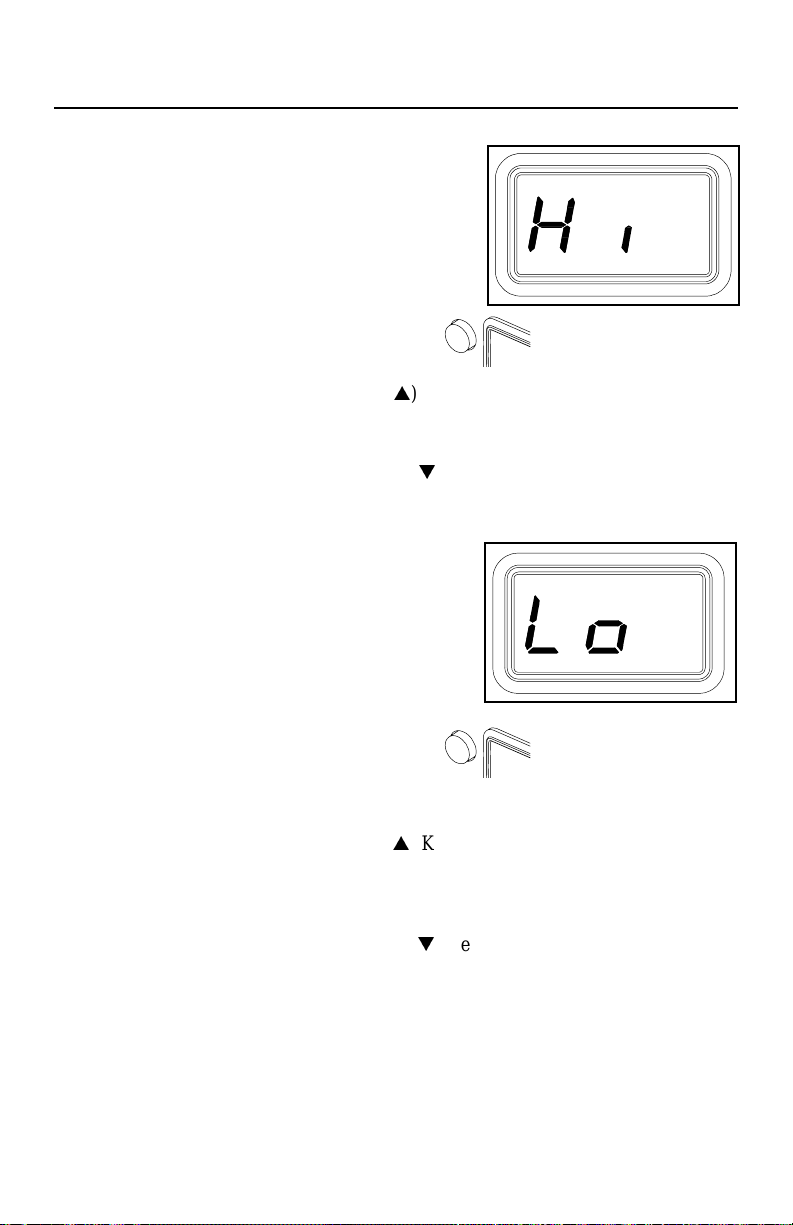
9 . The LED Display now shows the stored
default High ("Hi") T emperature Limit with the
display alternating to show "Hi" and the
stored limit. Choose one of the following:
a) Press and release the Program Key ( ) to keep the
stored High T emperature Limit.
b) Press and release the Scroll Up (s) Key to increase the stored High
T emperature Limit (up to 482°C, 900°F). Press and release the Program
Key to proceed to the next step.
b) Press and release the Scroll Down (t) Key to decrease the stored
High T emperature Limit. Press and release the Program Key to proceed
to the next step.
10. The LED Display now shows the stored
default Low ("Lo") T emperature Limit with the
display alternating to show "Lo" and the
stored limit. Choose one of the following:
Set-Up Mode
a) Press and release the Program Key ( )
to keep the stored Low T emperature Limit (204°C, 400°F).
b) Press and release the Scroll Up (s) Key to increase the stored Low
T emperature Limit. Press and release the Program Key to proceed to
the next step.
c) Press and release the Scroll Down (t) Key to decrease the stored Low
T emperature Limit. Press and release the Program Key to proceed to
the next step.
32
Page 35
Set-Up Mode
Offset Constant
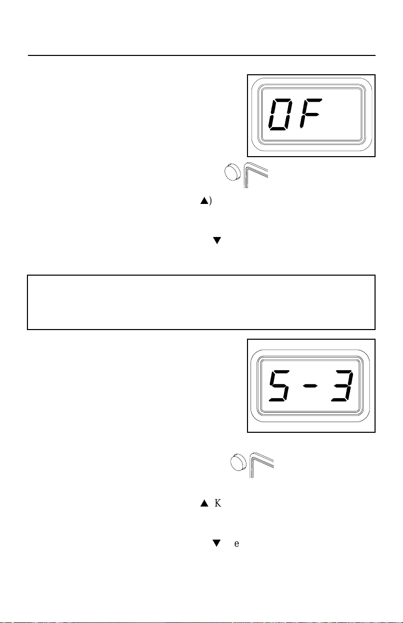
11. The LED Display now shows the stored
Offset Constant with the display alternating
to show "OF" and the stored Offset Constant.
Choose one of the following:
a) Press and release the Program Key ( ) to keep the
currently stored Offset Constant.
b) Press and release the Scroll Up (s) Key to increase the stored Offset
Constant. An Offset Constant of 0-133°C (0-240°F) can be stored.
Press and release the Program Key to proceed to the next step.
c) Press and release the Scroll Down (t) Key to decrease the stored
Offset Constant. Press and release the Program Key to proceed to the
next step.
NOTE
If the attached handpiece is disconnected when the system is powered up, any stored
Offset Constant is reset to zero. The Offset Constant must be entered again in the SetUp Mode.
Temperature Setback
12. The LED Display now shows the stored
T emperature Setback time as "S-X" (x=0 thru
9). Time is shown as tens of minutes (e.g., "S3" equals 30 minutes). A display of "S- 0"
indicates that Setback is disabled. Choose
one of the following:
a) Press and release the Program Key ( ) to keep the
currently stored T emperature Setback time.
b) Press and release the Scroll Up (s) Key to enable and/or increase the
stored T emperature Setback time. Press and release the Program Key
to proceed to the next step.
c) Press and release the Scroll Down (t) Key to decrease or disable the
stored T emperature Setback time. Press and release the Program Key
to proceed to the next step.
33
Page 36
Auto Off
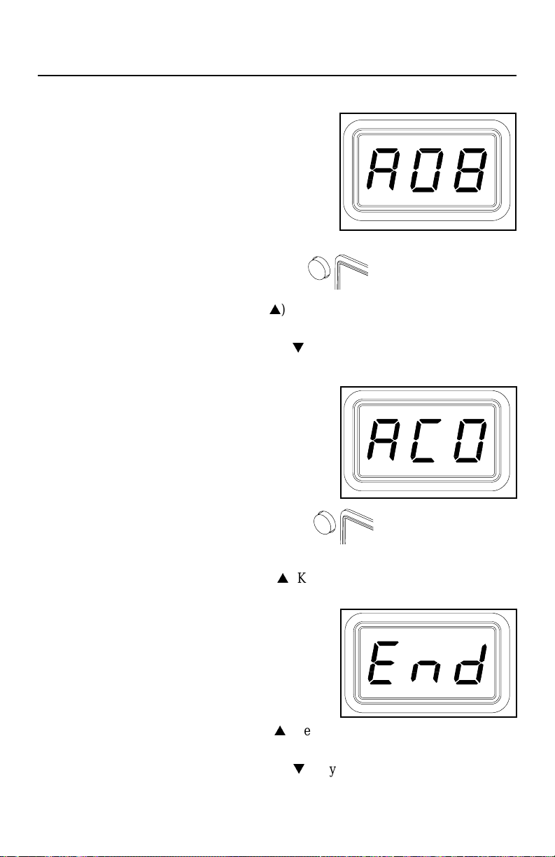
13. The LED Display now shows the stored Auto
Off time as "AOx" (x=0 thru 9). Time is shown
as tens of minutes (e.g., "AO3" equals 30
minutes). A display of "AO0" indicates that
Auto Off is disabled. Choose one of the
following:
a) Press and release the Program Key ( ) to keep the
currently stored Auto Off time.
b) Press and release the Scroll Up (s) Key to enable and/or increase the
Auto Off. Press and release the Program Key to proceed to the next step.
c) Press and release the Scroll Down (t) Key to decrease or disable the
stored Auto Off time. Press and release the Program Key to proceed to
the next step.
Temperature Display Impedance
14 . The LED Display now shows the T emperature
Display Impedance mode as Enabled or
Disabled ("AC0" = Disabled and "AC1" =
Enabled). Choose one of the following:
Set-Up Mode
a) Press and release the Program Key ( ) to keep the
currently stored setting (Disabled or Enabled).
b) Press and release the Scroll Up (s) Key to change the stored setting
(Disabled or Enabled). Press and release the Program Key to proceed
to the next step.
Exiting Set-Up Mode
15. The LED Display now reads "End". The SetUp Mode procedure is now complete.
Choose one of the following steps:
a) Press and release the Scroll Up (s) Key to exit Set-Up Mode and
return to normal operation.
b) Press and release the Scroll Down (t) Key to return to the start of the
Set-Up Mode procedure. Go back to step 4.
34
Page 37
Corrective Maintenance
LED Display Message Codes
Listed below are message codes which may be shown on the LED Display if a mistake
is made by the operator (e.g., wrong Password entry) or if the system has
malfunctioned.
LED Display
Message
The LED Display is flashing.
The LED Display is flashing.
The LED Display is flashing.
Description
The incorrect Password has been entered. The displayed
message will time out after 6 seconds and revert to normal
operation. Enter the correct Password.
No handpiece i s co nnected to the Power Receptacle.
C onne ct handpi ec e.
The handpiece heater assembly sensor is open. Refer to
Table 4 to check handpiece.
The handpiece heater assembly sensor is shorted. Refer to
Table 4 to check handpiece.
The handpiece heater assembly may be defective. Refer to
Table 4 to check handpiece.
Po wer s o urce malfuncti o n. C a ll the PACETechnica l Support
for assistance.
Tel. 1-888-535-7223 (toll-free), FAX 1-301-483-7030.
Table 2. LED Display Message Codes
35
Page 38

Corrective Maintenance
Power Source
Most malfunctions are simple and easy to correct. Refer to T able 3.
Symptom Probable Cause Solution
No power to system. Blown Fuse Check handpiece using Table 2. Replace the
No heat on
handpiece.
Defective Heater See Table 2.
fuse (located in the AC Receptacle/Fuse
Holder) with one of same value (see Table 4,
Spare Parts).
No vacuum or air
pressure at
handpiece.
House air supply
not connected.
Kinks in handpiece
Check house air supply connection to power
source.
Remove kinks or replace air hose.
Table 3. Power Source Corrective Maintenance
36
Page 39

Corrective Maintenance
Handpieces
The following “Heater Assembly Checkout Procedures” (Table 4) is applicable to
all PACE SensaTemp handpieces used with the ST 85 system except for the TT65 and DTP-80 handpieces. Refer to the applicable manuals for troubleshooting
procedures pertinent to that handpiece.
Perform the procedures with the handpiece heater at room temperature. If the heater
is warm, resistance readings will be different from those shown. Disconnect the
handpiece from the power source. Use a meter to check resistance across the
handpiece connector plug pins as outlined in the “Checkout Procedure” column.
Symptom Checkout Procedure Cause Solution
Handpiece
does not heat.
Handpiece
overheating.
Fuse blows
when unit is
turned on.
No Ground on
Tip.
Check resistance - Pin 2 to
Pin 5. Refer to "Heater
Specifications" column.
If resistance is high - -
Check resistance - Pin 3 to
P in 6. If circuit reads open -
Check resistance - Pin 3 to
Pin 6. Resistanc e should be
110 ohms. If resistance is
less than 105 ohms - -
Check resistance - Pin 2 to
Pin 5. Refer to "Heater
Specifications" column. If
resistance is low - -
Check resistance - Pin 4 to
a NEW Tip. Resistance
should be less than 2 ohms.
I f not - -
Open Heater Replace Heater
Open Sens or Replace Heater
Shorted
Sensor
Shorted
Heater
Oxidation in
Heater Bore.
Defective
Heater
Assembly.
Assembly.
Replace Heater
Assembly.
Replace Heater
Assembly & Fuse.
Clean Heater Bore
using appropriate
wire br ush.
Replace Heater
Assembly.
Heater Specifications
PS-80 = 8 - 1 0 ohms
PS-80 = 8 - 1 0 ohms
PS-80 = 8 - 1 0 ohmsPS-80 = 8 - 1 0 ohms
SX-80 = 8 - 1 0 ohms
SX-80 = 8 - 1 0 ohms
SX-80 = 8 - 1 0 ohmsSX-80 = 8 - 1 0 ohms
SX-70 = 8 - 1 0 ohms
SX-70 = 8 - 1 0 ohms
SX-70 = 8 - 1 0 ohmsSX-70 = 8 - 1 0 ohms
TP-65 = 9 - 11 ohms
TP-65 = 9 - 11 ohms
TP-65 = 9 - 11 ohmsTP-65 = 9 - 11 ohms
TJ-70 = 6 - 8 ohms
TJ-70 = 6 - 8 ohms
TJ-70 = 6 - 8 ohmsTJ-70 = 6 - 8 ohms
Table 4. Heater Assembly Checkout Procedures
Connector
Plug Pinouts
37
Page 40

Packing List/Spare Parts
Packing List
This is a packing list of the items shipped with the system and is current at the time of
publication of this manual.
PACKING LIST
Item#Description Part Number
1ST 85 System Power Source - - - - - 1111
2 SX-80 Handpiece, (48 Watts) 6010–0106 0 0 1 1
3 Power Supply Cord, 115 VAC 1332-0094 1 0 1 0
4 Power Supply Cord, 230 VAC 1332-0093 0 1 0 1
5 Tip & Tool Stand Kit 6019-0060-P1 0 0 1 1
6 SX-80 Access o ry Ki t - - - - - 0 0 1 1
7Tip Tool 1100–02061111
8 Air Fitting Adaptor 1259-0081 0 1 0 1
9Operation & Maintenance Manual5050-04551111
Quantity Supplied
ST 85
Systems
ST 85 ST 85E ST 85 ST 85E
ST 85-SX80
Systems
Table 5. Packing List
Spare Parts
Item # Description Part Number
1Fuse,
SX-80 Heater Asse mbly
2
Replac ement PCB Ass embly
3
Tip & Temperature Selection System Booklet.
4
1.0 Amp Time Lag (ST 85) 1159-0246
0.5 Amp Time Lag ( ST 85E) 1159-0213
6010-0107-P1
6020-0127-P1
5050-0251
Table 6. Spare Parts
38
Page 41

d
Warranty
LIMITED WA RR A N TY
PACE warrants that this equipment w ill be free of defects in materials and workm anship for a
period of one (1) year from th e date of receipt by the first user.
T his warranty does not cover repair or replacement required as a result of misuse, mishandling or improper
storage. Failure to perform recommended routine maintenance, alterations or repairs made other than i n
accordance with PAC E’s directions, or removal or alteration of identification plates in an y way will void this
warranty. This warranty is available only to the first user, but the exclusions and limitations therein apply to all
persons and entities.
T his warranty does not apply to consumable items, such as tips, filter elements, hoses, collection chambers
etc., ex cept that heaters are normally warranted for a period of six (6) months from the date of receipt by the
first user.
PACE MAKES NO OTHER WARRANTY , EXPRESSED OR IMPLIED, AND MAKES NO
WARRANTY OF MERCHANTABILITY OR FITNESS FOR A PARTICULAR PURPOSE.
PACE will, at its option, repair or replace any defective equipment or parts at its facility or other location
approved by it at no charge to the user, or provide parts without charge for instal lation by the user in the fiel
at user’s expense and risk. User will be responsible for all costs of shipping equipment to PACE or other
warranty location for warranty service.
EXCEPT FOR THE REMEDY ABOVE DESCRIBED, UNLESS OTHERWISE REQUIRED BY
APPLICABLE LAW, PACE WILL HAVE NO OTHER OBLIGATION WITH REGARD TO ANY
BREACH OF WARRANTY OR OTHER CLAIM WITH RESPECT TO THE EQUIPMENT, OR
LIABILITY FOR ANY DIRECT, INDIRECT, CONSEQUENTIAL, OR INCIDENTAL LOSS OR
DAMAGE CAUSED BY OR OCCURRING IN CONNECTION WITH ANY OF THE EQUIPMENT.
To obtain warranty service, contact the appropriate PACE company listed below
PACE Inc. 9893 Brew ers Court, Laurel, Maryland 20723-1990
Tel. (888) 535-7223 (toll-free) Warranty Service FAX 301 483 7030
PACE Europe Ltd. Sherbourne House Sherbourne Drive Tilbrook Milton Keyn es
United Kingdom MK7 8HX
Tel. (44) 01908 277 666 Warranty Service FAX (44) 01908 277 777
Do NOT return defective equipment or parts to PACE withou t obtaining prior authorization.
Any warranty or other claim w ith respect to the equipment must be made in writing and delivered to PACE
(or local authorized PACE Distribu tor outside the U.S.) within a reasonable time of the expiration date of this
warranty. Sufficient evidence of purchase and date of receipt must al so be in cluded, otherwise user’s rights
under this warranty shall be deemed waived.
39
 Loading...