

Page 1

ST 70
7008-0293-01
ST 70E
7008-0293-02
ST 75
7008-0294-01
ST 75E
7008-0294-02
ST 115
7008-0295-01
ST 115E
7008-0295-02
Operation and Maintenance Manual for
IntelliHeat™ Power Sources
P/N 5050-00556 REV. 03/22/2013
This manual applies to:
Model Part Number
ST 30 7008-0290-01
ST 30E 7008-0290-02
ST 50 7008-0291-01
ST 50E 7008-0291-02
ST 65 7008-0292-01
ST 65E 7008-0292-02
www.ekt2 .com
Page 2

General Information
Domestic Models
ST 30
Operates on 97-127 VAC,
50/60Hz, 80 Watts maximum at
115 VAC, 60Hz
Operates on 197-253 VAC
50/60Hz, 80 Watts maximum at
230 VAC, 50Hz
ST 50
ST 65
ST 70
ST 75
ST 115
Introduction
The systems featured in this guide are available in either 115 VAC or 230 VAC versions. All of these
models incorporate Intelliheat™ technology. Intelliheat™ is the combination of THC (Tip Heater
Cartridge) and SensaTemp handpieces into one system. The system recognizes either handpiece
individually and automatically adjusts the menu driving controls for each handpiece. The 230 VAC
version system bears the CE Conformity Marking, which assures the user that it conforms to EMC
89/336/EEC. All models featured in this manual are lead free compatible and comply with RoHS and
WEEE directives.
Specifications
Power Source Requirements
Export Models
ST 30E
ST 50E
ST 65E
ST 70E
ST 75E
ST 115E
Shop Air Input Requirements (ST 65 Only)
Pressure- 5.48 Bar (80p.si.) recommended
Airflow- 45.3 SLPM (1.6SCFM) minimum
Temperature Specifications (All Models)
Tip Heater Cartridge Handpiece Tip Temperature Range: 205 to 455°C (400 to 850°F) nominal.
SensaTemp Handpieces Tip Temperature Range: 37 to 482°C (100 to 900°F) nominal.
Digital Readout Resolution: ±5° (°C or °F)
Tip Temperature Stability: ±1.1°C (2°F) at Idle from Set Tip Temperature.
Temperature Accuracy: Meets or exceeds ANSI JSTD 001
VACUUM AND AIR (ST 65 ST 75 & ST 115) Measurements at front panel AUTO SNAP-VAC and
CONTROLLABLE PRESSURE Port.
Vacuum Rise Time: 150 ms average.
Vacuum: 20 in. Hg. (Nominal)
Pressure: (18 P.S.I.) (Nominal MAXIMUM setting)
Air Flow: 8 SLPM MAXIMUM
EOS/ESD Specifications (All Models)
Tip-To-Ground Resistance: Less than 2 ohms.
AC Leakage: Less than 2 Millivolts RMS from 50Hz to 100MHz.
Transient Level: Less than 500mV peak, out to 100MHz.
www.ekt2 .com
Page 3

Power Supply Features
ST 30
ST 50
FRONT
BACK
ST 65
www.ekt2 .com
Page 4

ST 75
ST 70
ST 115
www.ekt2 .com
Page 5
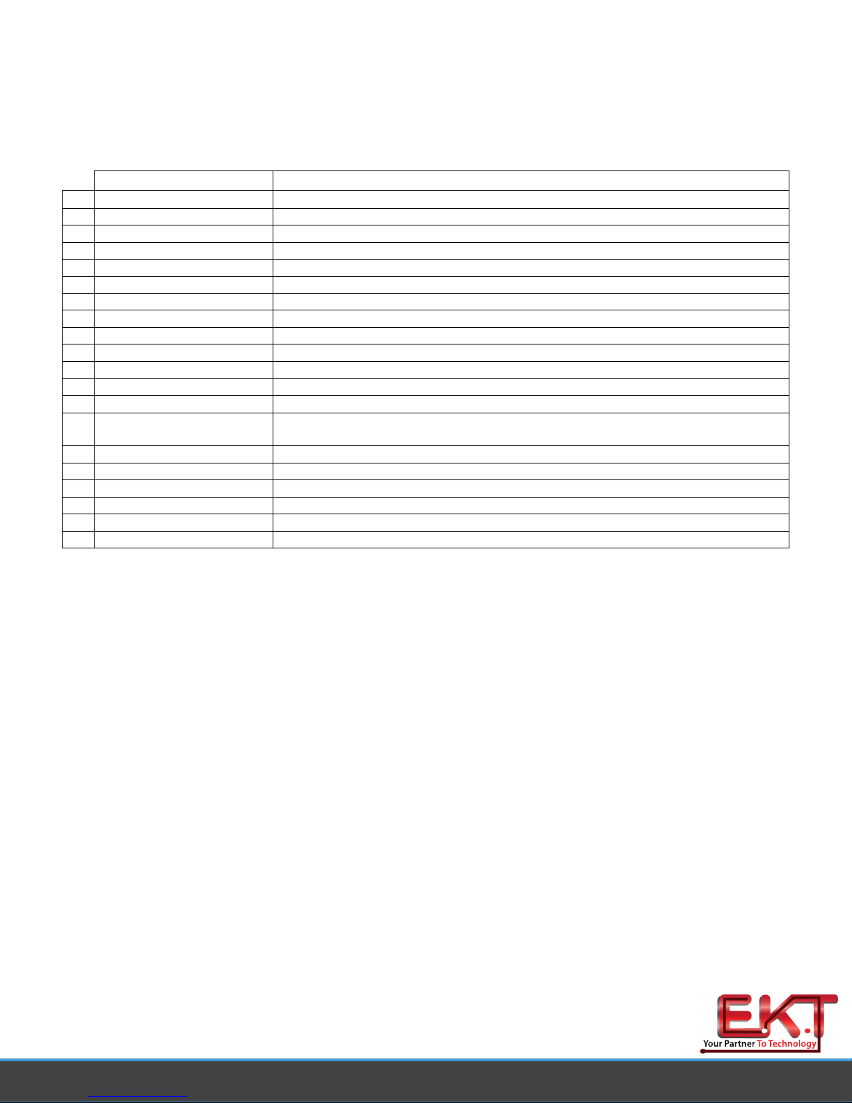
Feature Description
A Analog control knob Regulates tip temperature on ST 30, ST 65, & ST 75 power supplies.
B THC fine control For fine adjustment of true tip temperature (Tip heater Cartridge handpieces only).
C Power switch On /off control of power supply.
D Analog control LED Indicates status of power supply.
E Power Receptacle Front panel connection of handpiece.
F Program button For access and confirmation of program menu functions.
G Up arrow button Increase set temperature and scroll through program menu functions.
H Down arrow button Decrease set temperature and scroll through program menu functions.
I Digital control LED Indicates status of power supply.
J Digital display Displays temperature setting and menu functions.
K Vacuum inlet Vacuum connection for SX-90, TP-65, & TP-100 Handpieces.
L Pressure control valve / port Pressure / airflow connection and control for TJ-85 handpiece.
M Power module LED Indicates status of power supply.
Allows user to increase or decrease performance level using individual power
N Power module jack
O Ground jack For ground system to static safe work area.
P ISB connection Connection for Instant Set Back cubby.
Q Power inlet with fuse Connection for IEC power cord and fuse replacement.
R Auto off switch Activates auto off feature
S Shop air connection Connection for regulated air supply (ST 65 power supply only)
T Foot pedal connection Optional control for pressure / vacuum handpiece activation. (Required for TJ-85)
modules.
Made in U.S.A
www.ekt2 .com
 Loading...