

Page 1

Operation and Maintenance Manual for the
SODRTEK
ST 600 Digital Paste Dispensing System
P/N 5050-0538
®
Page 2

TITLE PAGE
General Information
Introduction...........................................................................................................3
Specifications .......................................................................................................3
Parts Identification................................................................................................4
Safety.............................................................................................................................5
Safety Guidelines.................................................................................................5
System Set-Up...............................................................................................................6
Hose Barrel Connection ..........................................................................................6
Material Loading......................................................................................................6
System Power Up ..........................................................................................................6
Operation........................................................................................................................7
Adjustment of Dispensing Modes.........................................................................8
Helpful Hints for Proper Dispensing...............................................................................9
Tip Selection .................................................................................................................10
Corrective Maintenance................................................................................................10
Packing List...................................................................................................................11
Spare Parts and Accessories........................................................................................12
Service ..........................................................................................................................13
“SODRTEK by PACE” LIMITED WARRANTY STATEMENT.......................................14
Contact Information.......................................................................................................15
©2004 PACE Inc., Annapolis Junction, Maryland Page 2 of 15
All Rights Reserved
Page 3

General Information
Introduction
Thank you for purchasing the PACE SODRTEK
®
model ST 600 Digital Paste Dispensing System.
This manual will provide you with the information necessary to properly set up, operate and maintain
your new system. This ST 600 is a microprocessor controlled, automatic liquid dispensing system.
The pressure is fully adjustable for each individual application and the dispensing cycle time allows
for precise dispensing of liquids such as glues, greases, and solde r paste s.
The ST 600 system is available in either 115 VAC or 230 VAC versions. The 230 VAC version
system bears the CE Conformity Marking, which assures the user that it conforms to EMC
89/336/EEC.
The 115 VAC version systems conform to FCC Emission Control Standard, Title 47, Subpart B, Class
A. This standard is designed to provide reasonable protection against harmful interference when the
equipment is operated in a commercial environment.
Specifications
System Power Source Power Requirements
ST 600 Operates on 97-127 VAC, 50/60Hz, 90 Watts maximum at 115 VAC,
60Hz
ST 600E Operates on 197-253 VAC 50/60Hz, 80 Watts maximum at 230 VAC,
50Hz
Dispensing Time 0.01-99.99Seconds Adjustable
Timing Intervals 0.1-9.9Seconds Adjustable
Repeat Tolerance ±0.05%
Size 23.8 cm x 15.0 cm x 6.0 cm (9.37” x 5.9” x 2.36”)
Weight 1.7Kg (3.75 Lbs)
Internal Voltage 24V DC
Air Input 35-100 PSI (0.25-0.7MPa)
Air Output 1-100 PSI (0.01-0.7Mpa)
©2004 PACE Inc., Annapolis Junction, Maryland Page 3 of 15
All Rights Reserved
Page 4
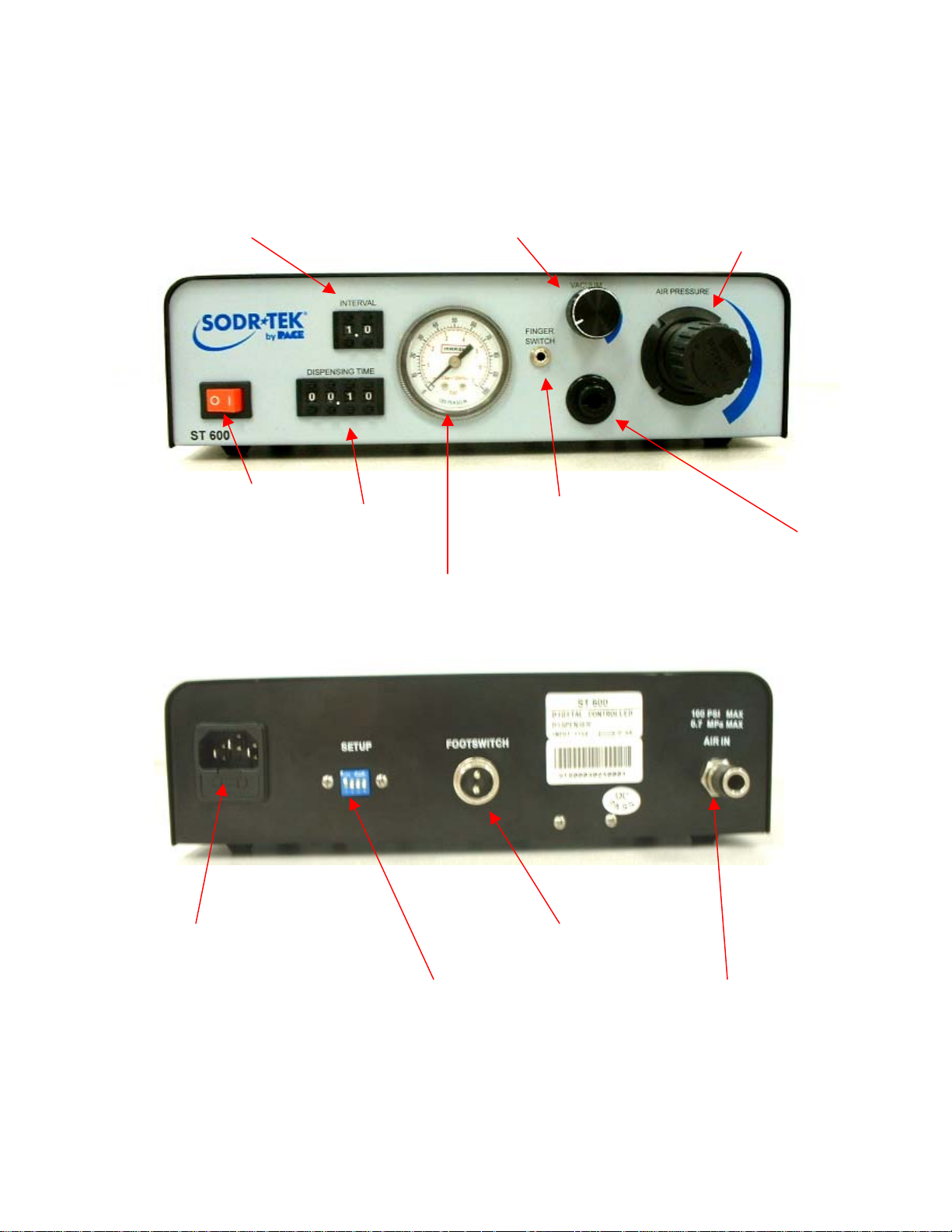
Parts Identification
A
g
p
g
A
A
g
Interval Time Indicators/Buttons Vacuum Control Knob
Dispensing Time
Indicators/Buttons
Fin
er Switch ReceptaclePower Switch
ir Pressure Gauge
ir Pressure Control Knob
ensing Output Pressure Fittin
Dis
AC Power Receptacle/Fuse Holder
Dispensing Mode DIP Switches
©2004 PACE Inc., Annapolis Junction, Maryland Page 4 of 15
All Rights Reserved
Foot Pedal Receptacle
ir Input Fittin
Page 5

Safety
Safety Guidelines
The following are safety precautions that personnel must understand and follow when using or
servicing this product. These precautions may or may not be included elsewhere in this manual.
1. POTENTIAL SHOCK HAZARD - Repair procedures on PACE products should be
performed by Qualified Service Personnel only. Line voltage parts may be exposed
when the equipment is disassembled. Service personnel must avoid contact with these
parts when troubleshooting the product.
2. To prevent personnel injury, adhere to safety guidelines in accordance with OSHA and
other applicable safety standards.
3. Always use PACE systems in a well ventilated area. A fume extraction system such as
those available from PACE are highly recommended to help protect personnel from
solder flux fumes.
4. Exercise proper precautions when using chemicals (e.g., solder paste). Refer to the Material
Safety Data Sheet (MSDS) supplied with each chemical and adhere to all safety precautions
recommended by the manufacturer.
5. Do not exceed 7 Bar (100 PSI), otherwise damage to equipment, materials, and the operator
could occur.
6. Personnel who handle dispensing materials should wash their hands and face thoroughly
before eating, smoking or using rest room facilities.
7. Proper training should be given to personnel handling these materials.
8. The use of Safety Glasses is recommended when loading the barrels.
©2004 PACE Inc., Annapolis Junction, Maryland Page 5 of 15
All Rights Reserved
Page 6

System Set-Up
Hose/Barrel Connection
1. Connect the shop air supply to the unit’s air input plug.
2. Attach the ridged end of the male quick connect hose mount Fitting to the Air Hose.
3. Insert the male hose mount fitting (attached to Air Hose) into the
female Dispensing Output Pressure Fitting.
4. Slide the Hose Clamp over the free end of the Air Hose. Push
clamp back 1 inch from the end of the Air Hose.
5. Attach the free end of the Air Hose to the nipple on the Barrel
Adapter (10 cc adapter is supplied).
6. Secure the Air Hose to the Barrel Adapter by sliding the Hose
Clamp down over the Air Hose/Barrel Adapter connection and screwing clamp down to secure in
position.
7. Attach the Barrel Adapter to a preloaded barrel (not supplied). Place the barrel in the
Dispenser Cubby.
10. Insure that the foot pedal is connected to the FOOT PEDAL Receptacle on the rear panel.
Material Loading
PACE recommends the use of preloaded barrels whenever practical to
minimize any handling or safety precaution requirements. When
loading is required, adhere to all precautions recommended by the
material manufacturer. Refer to the Material Safety Data Sheet
supplied with each material for information on important safety
procedures and a listing of any toxic chemical elements.
Loading of low viscosity materials are easily accomplished by placing
an empty Barrel (with barrel tip cap installed) into the Pik & Paste.
Pour the material slowly into the barrel using a Squeeze Bottle or small
funnel.
Caution: Fill the Barrel to a level of no more than 2/3 or the Barrel capacity. Dispensed amount
variations will be avoided and the material will be prevented from getting on the Barrel
adapter. Do not allow the Barrel to tip upside down or lay flat. Damage may occur to
the motor pump if fluid leaks back into the system through the air hose.
System Power Up
Plug the prong end (male end) of the power cord into an appropriate 3 wire grounded AC supply
receptacle.
NOTE: Make sure the power supply socket is properly grounded with the corresponding volta ge.
©2004 PACE Inc., Annapolis Junction, Maryland Page 6 of 15
All Rights Reserved
Page 7

Operation
1. Turn the unit “on” by switching the red power button to the on position.
2. Pull the air pressure regulator knob outward and turn clockwise to increase the
air pressure until the desired pressure is indicated.
NOTE: The air pressure output should generally be used between 0.1-2.7bar
(1-40Psi).
3. Set the mode switch to proper position, referring to the adjustment of
dispensing time and interval time.
4. Adjust the dispensing time via the buttons on the front panel. To
adjust, press the “+” button to increase the time and press the “-“
button to decrease the time. There are four digits in all; with the range
from 0.01 second to 99.99 seconds, and the resolution is 0.01 second.
5. Adjust the Interval Time via the buttons on the front panel. To adjust,
press the “+” button to increase the time and press the “-“ button to
decrease the time. There are two digits in all; with the range from 0.1
second to 9.9 seconds, and the resolution is 0.1 second.
6. Adjust the vacuum via the Vacuum Control Knob, which is located on the front panel. Turn
clockwise to increase the vacuum and turn the Vacuum Control Knob counterclockwise to
decrease the vacuum. The vacuum should be adjusted during the dispensing cycle. This
function is used to prevent the material from oozing after the material
has been dispensed.
NOTE: The barrel material will not drip or ooze unless it has a low
viscosity level. I dripping or oozing does not occur, leave the
Vacuum Control Knob set the fully counterclockwise position.
To high of a vacuum setting could case the material to be
sucked back into the system thus possibly damaging the
station.
7. Insure that the proper material (in barrel) and tip have been installed.
8. Wipe any material residue from the end of tip.
©2004 PACE Inc., Annapolis Junction, Maryland Page 7 of 15
All Rights Reserved
Page 8

9. Hold the barrel at approximately 60° (+ or -20°) angle, rest the tip on a piece of paper and
dispense a small amount of material. This initial dispensing will fill the tip with material.
10. Depress the foot pedal to dispense material.
11. Place barrel in Dispenser Cubby when dispensing operation is
complete.
NOTE: Condensation may occur in the air hose after extended
use. This is a normal occurrence. To remove the
condensation, disconnect the air hose from the barrel adapter and actuate the dispense
pump. The air pressure will blow the condensation from the air hose.
Adjustment of Dispensing Modes
The Mode Switch is located on the rear panel of the unit. Please refer to the table below for the
settings.
NOTE: Dispensing at controlled time means dispensing accordin g to set dispensing and interval
times.
ON
21
34
Item
No.
1 OFF OFF OFF OFF
Mode Switch Status
S1 S2 S3 S4
Function
With pedal switch pressed, dispense continuously,
otherwise it will stop dispensing.
2 ON OFF OFF OFF Be triggered once, dispense at controlled time once.
3 OFF ON OFF OFF Be triggered once, dispense at controlled time twice.
4 ON ON OFF OFF
5 OFF OFF ON OFF
Be triggered once, dispense at controlled time three
times.
Be triggered once, dispense at controlled time four
times.
6 ON OFF ON OFF Be triggered once, dispense at controlled time five times.
7 OFF ON ON OFF Be triggered once, dispense at controlled time six times.
8 ON ON ON OFF
9 OFF OFF OFF ON
10 ON OFF OFF ON
Be triggered once, dispense at controlled time seven
times.
Be triggered once, dispense at controlled time eight
times.
Be triggered once, dispense at controlled time nine
times.
11 OFF ON OFF ON Be triggered once, dispense at controlled time ten times.
12 ON ON OFF ON
13 OFF OFF ON ON
Be triggered once, dispense at controlled time eleven
times.
Be triggered once, dispense at controlled time twelve
times.
©2004 PACE Inc., Annapolis Junction, Maryland Page 8 of 15
All Rights Reserved
Page 9

14 ON OFF ON ON
15 OFF ON ON ON
16 ON ON ON ON
Be triggered once, dispense at controlled time
continually, the next trigger will stop the dispensing.
With pedal switch pressed, dispense at controlled time
continually, or it will stop dispensing.
Dispense at controlled time continually and
automatically.
Helpful Hints for Proper Dispensing
PACE recommends that the operator become familiar with the operation of the dispenser by first applying
the material to a piece of paper or scrap PC board. Use this method to obtain the desired results for each
dispensing material and application.
1. Do not permit the liquid to flow back into the controller as shown.
2. Increase or decrease the size of the dots by either, increasing or decreasing the time,
Or
Increasing or decreasing the pressure,
Or
Increasing or decreasing the size of the tip.
3. Make certain that the air supply is clean and dry.
4. The output air pressure should be regulated at 0.1-0.27 Mpa (15-40 PSI).
5. When dispensing different dot sizes, select a tip/time combination, which dispenses small dots.
These small dots may be dispensed in multiples to provide the deposition amount required. Use
of the feature in this manner can eliminate frequent tip changes and dispense cycle time
adjustments.
6. In situations where the metal tip may scratch or damage the work, install a short section of heat
shrinkable tubing or sleeving. The tubing (or sleeving) should extend 1.5 mm (1/16”) past the tip
end.
7. Keep all dispenser components clean to prevent clogging and/or irregular deposition.
©2004 PACE Inc., Annapolis Junction, Maryland Page 9 of 15
All Rights Reserved
Page 10

8. Avoid turning barrels upside down or laying barrel, so that material may run through the vacuum
line to the internal components.
9. Do not allow the barrel assemblies to contact hot or sharp objects.
10. Avoid exposing the liquid dispenser to excessive moisture or solvent situations.
NOTE: Dispose of all tips and barrels after use. Always use new tips and barrels to prevent
contamination, insure cleanliness and provide consistent, repeatable material deposition.
Tip Selection
Selection of the proper tip for the application is essential to obtain the optimum deposition rate and
amount. Check the specifications of the material manufacturer for recommended tip sizing. The tip size
and duration of the dispense cycle determine amount of material deposition (dot or bead size). Dispense
several dots (or beads) onto a piece of paper or scrap PC board to check for desired results.
Corrective Maintenance
Most malfunctions are simple and easy to correct.
Symptom Probable Cause Solution
No power to
system
Blown Fuse
Replace fuse.
Bad internal connection Unplug from wall, remove top cover, and visually
inspect for any loose or shorted connection.
No voltage from wall outlet Check the facility breaker/wiring.
Power, but no
Power Switch Replace power switch.
light
Has power and
light but does
not operate
Bad connection Check foot switch (or finger switch) connection.
Unplug from wall, remove top cover and check for
loose connection.
Has power and
light but does
not dispense
Reduced or no airflow Check air supply and pressure gauge. Reset the
regulator if necessary, remove barrel from
adapter. Depress foot switch (or finger switch) to
check airflow.
Clean or replace solenoid as necessary.
Solenoid buzzes
Voltage is low
Verify AC receptacle voltage.
Air is insufficient
Check air supply and pressure gauge.
Solenoid is not clean
Clean or replace solenoid as necessary.
Blowing fuse
Incorrect rated fuse
Verify the rating of the fuse.
Internal short Unplug power input, remove cover, and check
internal wiring for loose connection.
©2004 PACE Inc., Annapolis Junction, Maryland Page 10 of 15
All Rights Reserved
Page 11

Inconsistent
dots
Clogged tip
Check needles, barrel, adapter, and material for
possible clogging.
Aerated material Check bubbles in the material.
Pressure variation Check air gauge for air pressure variation.
Dispensing ok,
but no vacuum
in dispense
circuit
Incorrect vacuum
adjustment
Incorrect air pressure
setting
Check vacuum adjustment setting.
Check air pressure setting (must be 30-40 Psi,
0.2-0.27 Mpa).
Packing List
Item # Description Part Number ST 600
Only
1 System Power Supply 8007-0439 1 0
2 System Power Supply
(Export)
3 Power cable (Domestic) 1 0
4 Power cable (Export) 0 1
5 Foot Pedal 1 1
6 Barrel rack 1 1
7 Air-input tube (3m) 1 1
8 10cc Barrel Adapter 1 1
9 Finger Switch Assembly 6008-0143-P1 1 1
10 Fuse (120V, 0.25A) 1 0
11 Fuse (230V, 0.5A) 0 1
12 Operations Manual CD CD5050-0459 1 1
8007-0440 0 1
ST 600 E
Only
©2004 PACE Inc., Annapolis Junction, Maryland Page 11 of 15
All Rights Reserved
Page 12

Spare Parts and Accessories
Item # Description PACE Part Number
1 Finger Switch Assembly 6008-0143-P1
2 Threaded hub, 14GA, 0.5" 1125-0001-P10
3 Threaded hub, 14GA, 0.5" 1125-0001-P50
4 Threaded hub, 15GA, 0.5" 1125-0002-P10
5 Threaded hub, 15GA, 0.5" 1125-0002-P50
6 Threaded hub, 16GA, 0.5" 1125-0003-P10
7 Threaded hub, 16GA, 0.5" 1125-0003-P50
8 Threaded hub, 17GA, 0.5" 1125-0004-P10
9 Threaded hub, 17GA, 0.5" 1125-0004-P50
10 Threaded hub, 18GA, 0.5" 1125-0005-P10
11 Threaded hub, 18GA, 0.5" 1125-0005-P50
12 Threaded hub, 19GA, 0.5" 1125-0006-P10
13 Threaded hub, 19GA, 0.5" 1125-0006-P50
14 Threaded hub, 20GA, 0.5" 1125-0007-P10
15 Threaded hub, 20GA, 0.5" 1125-0007-P50
16 Threaded hub, 21GA, 0.5" 1125-0008-P10
17 Threaded hub, 21GA, 0.5" 1125-0008-P50
18 Threaded hub, 22GA, 0.5" 1125-0009-P10
19 Threaded hub, 22GA, 0.5" 1125-0009-P50
20 Threaded hub, 23GA, 0.5" 1125-0010-P10
21 Threaded hub, 23GA, 0.5" 1125-0010-P50
22 Threaded hub, 24GA, 0.5" 1125-0011-P10
23 Threaded hub, 24GA, 0.5" 1125-0011-P50
24 Threaded hub, 25GA, 0.5" 1125-0012-P10
25 Threaded hub, 25GA, 0.5" 1125-0012-P50
26 Threaded hub, 26GA, 0.5" 1125-0013-P10
27 Threaded hub, 26GA, 0.5" 1125-0013-P50
28 Threaded hub, 27GA, 0.5" 1125-0014-P10
29 Threaded hub, 27GA, 0.5" 1125-0014-P50
30 Threaded hub, 30GA, 0.5" 1125-0015-P10
31 Threaded hub, 30GA, 0.5" 1125-0015-P50
32 Threaded hub, 14GA, 0.1" 1125-0016-P10
33 Threaded hub, 14GA, 0.1" 1125-0016-P50
34 Threaded hub, 15GA, 0.1" 1125-0017-P10
35 Threaded hub, 15GA, 0.1" 1125-0017-P50
36 Threaded hub, 16GA, 0.1" 1125-0018-P10
37 Threaded hub, 16GA, 0.1" 1125-0018-P50
38 Threaded hub, 17GA, 0.1" 1125-0019-P10
39 Threaded hub, 17GA, 0.1" 1125-0019-P50
40 Threaded hub, 18GA, 0.1" 1125-0020-P10
41 Threaded hub, 18GA, 0.1" 1125-0020-P50
42 Threaded hub, 19GA, 0.1" 1125-0041-P10
43 Threaded hub, 20GA, 0.1" 1125-0021-P10
44 Threaded hub, 19GA, 0.1" 1125-0021-P50
45 Threaded hub, 20GA, 0.1" 1125-0041-P50
46 Threaded hub, 21GA, 0.1" 1125-0022-P10
47 Threaded hub, 21GA, 0.1" 1125-0022-P50
48 Threaded hub, 22GA, 0.1" 1125-0023-P10
49 Threaded hub, 22GA, 0.1" 1125-0023-P50
50 Threaded hub, 23GA, 0.1" 1125-0024-P10
©2004 PACE Inc., Annapolis Junction, Maryland Page 12 of 15
All Rights Reserved
Page 13

51 Threaded hub, 23GA, 0.1" 1125-0024-P50
52 Threaded hub, 24GA, 0.1" 1125-0025-P10
53 Threaded hub, 24GA, 0.1" 1125-0025-P50
54 Threaded hub, 25GA, 0.1" 1125-0026-P10
55 Threaded hub, 25GA, 0.1" 1125-0026-P50
56 Threaded hub, 26GA, 0.1" 1125-0027-P10
57 Threaded hub, 26GA, 0.1" 1125-0027-P50
58 Threaded hub, 27GA, 0.1" 1125-0028-P10
59 Threaded hub, 27GA, 0.1" 1125-0028-P50
60 Threaded hub, 30GA, 0.1" 1125-0029-P10
61 Threaded hub, 30GA, 0.1" 1125-0029-P50
62 Tip, Plastic, Taper, 14GA 1125-0030-P10
63 Tip, Plastic, Taper, 14GA 1125-0030-P50
64 Tip, Plastic, Taper, 16GA 1125-0031-P10
65 Tip, Plastic, Taper, 16GA 1125-0031-P50
66 Tip, Plastic, Taper, 18GA 1125-0032-P10
67 Tip, Plastic, Taper, 18GA 1125-0032-P50
68 Tip, Plastic, Taper, 20GA 1125-0033-P10
69 Tip, Plastic, Taper, 20GA 1125-0033-P50
70 Tip, Plastic, Taper, 22GA 1125-0034-P10
71 Tip, Plastic, Taper, 22GA 1125-0034-P50
72 Adapter, syringe, 5cc 1125-0035-P1
73 Adapter, syringe, 10cc 1125-0036-P1
74 Adapter, syringe, 30cc 1125-0037-P1
75 Barrel/Stopper, 5cc, 40 bag 1125-0038-P1
76 Barrel/Stopper, 5cc, 40 bag 1125-0038-P5
77 Barrel/Stopper, 10cc, 40 bag 1125-0039-P1
78 Barrel/Stopper, 10cc, 40 bag 1125-0039-P5
79 Barrel/Stopper, 30cc, 40 bag 1125-0040-P1
80 Barrel/Stopper, 30cc, 40 bag 1125-0040-P5
Service
Please contact PACE or your local distributor for service and repair.
©2004 PACE Inc., Annapolis Junction, Maryland Page 13 of 15
All Rights Reserved
Page 14

“SODRTEK by PACE” LIMITED WARRANTY STATEMENT
Limited Warranty
Seller warrants to the first user that products manufactured by it and supplied hereunder are free of
defects in materials and workmanship for a period of one (1) year from the date of receipt by such user.
Monitors, computers and other brand equipment supplied but not manufactured by PACE are covered
under their respective manufacturer’s warranty in lieu of this Warranty.
This warranty does not cover wear and tear under normal use, repair or replacement required as a result
of misuse, improper application, mishandling or improper storage. Consumable items such as tips,
heaters, filters, etc. which wear out under normal use are excluded. Failure to perform recommended
routine maintenance, alterations or repairs made other than in accordance with Seller’s directions, or
removal or alteration of identification markings in any way will void this warranty. This warranty is
available only to the first user, but the exclusions and limitations herein apply to all persons and entities.
SELLER MAKES NO OTHER WARRANTY, EXPRESS OR IMPLIED, AND MAKES NO WARRANTY OF
MERCHANTABILITY OR FITNESS FOR A PARTICULAR PURPOSE.
Seller will, at its option, repair or replace any defective products at its facility or other location approved by
it at no charge to user, or provide parts without charge for installation by the user in the field at user’s
expense and risk. User will be responsible for all costs of shipping equipment to Seller or other location
for warranty service.
EXCEPT FOR THE REMEDY ABOVE DESCRIBED, UNLESS OTHERWISE REQUIRED BY
APPLICABLE LAW, SELLER WILL HAVE NO OTHER OBLIGATION WITH REGARD TO ANY BREACH
OF WARRANTY OR OTHER CLAIM WITH RESPECT TO THE PRODUCTS, OR LIABILITY FOR ANY
DIRECT, INDIRECT, CONSEQUENTIAL, OR INCIDENTAL LOSS OR DAMAGE CAUSED BY OR
OCCURRING IN CONNECTION WITH ANY OF THE PRODUCTS.
Warranty service may be obtained by contacting the appropriate PACE Company or local Authorized
PACE distributor as set forth below to determine if return of any item is required, or if repairs can be made
by the user in the field. Any warranty or other claim with respect to the products must be made with
sufficient evidence of purchase and date of receipt, otherwise user’s rights under this warranty shall be
deemed waived.
For PACE USA Customers:
PACE, INCORPORATED
9030 Junction Drive
Annapolis Junction, Maryland 20701
Tel. 301-317-3588
FAX. 301-498-3252
For PACE EUROPE Customers:
PACE EUROPE LIMITED
Sherbourne House, Sherbourne Drive,
Tilbrook, Milton Keynes
MK7 8HX
United Kingdom
Tel. (44) 1908 277666
WARRANTY SERVICE FAX: (44) 1908 277 777
All other Customers:
Local Authorized PACE Distributor
©2004 PACE Inc., Annapolis Junction, Maryland Page 14 of 15
All Rights Reserved
Page 15

PACE Incorporated retains the right to make changes to specifications contained herein at any time,
without notice. Contact your local authorized PACE Distributor or PACE Incorporated to obtain the latest
specifications.
The following are trademarks and/or service marks of PACE, Incorporated, MD, USA:
INSTACAL
POWERPORT
™
, FUMEFLO™, HEATWISE™, PACEWORLDWIDE™, PERMAGROUND™,
™
, POWERMODULE™, TEMPWISE™, TIP-BRITE™, AUTO-OFF™, and
TEKLINK™.
The following are registered trademarks and/or service marks of PACE Incorporated, Annapolis Junction
Maryland U.S.A.
ARM-EVAC
SODRTEK
VISIFILTER
®
, FLO-D-SODR®, MINIWAVE®, PACE®, SENSATEMP®, SNAP-VAC®,
®
, SODR-X-TRACTOR®, THERMOFLO®, THERMOJET®, THERMOTWEEZ®,
®
, THERMO-DRIVE®, and TOOLNET®.
PACE products meet or exceed all applicable military and civilian EOS/ESD, temperature stability and
other specifications including MIL STD 2000, ANSI/JSTD 001, IPC7711, and IPC A-610.
www.paceworldwide.com
PACE USA PACE Europe
9030 Junction Drive Sherbourne House
Annapolis Junction, MD 20701 Sherbourne Drive
USA Tilbrook, Milton Keynes
MK7 8HX
United Kingdom
Tel: (301) 490-9860 (44) 01908-277666
Fax: (301) 498-3252 (44) 01908-277777
©2004 PACE Inc., Annapolis Junction, Maryland Page 15 of 15
All Rights Reserved
 Loading...