

Page 1

Operation and Maintenance Manual for the
®
SODRTEK
Radiant Pre-Heating System
P/N 5050-0540
ST 400
Page 2

TITLE PAGE
General Information .......................................................................................................3
Introduction...........................................................................................................3
Specifications .......................................................................................................3
Physical Parameters ............................................................................................3
Parts Identification................................................................................................4
Safety.............................................................................................................................5
Safety Guidelines.................................................................................................5
Preheating Basics..........................................................................................................5
System Power Up ..........................................................................................................6
Operation........................................................................................................................6
LED Operation......................................................................................................6
Variable Temperature Control..............................................................................7
Corrective Maintenance.................................................................................................7
General Maintenance...........................................................................................7
Heater Replacement ............................................................................................7
Power Source......................................................................................................12
Packing List...................................................................................................................12
Spare Parts...................................................................................................................12
Service ..........................................................................................................................12
“SODRTEK by PACE” LIMITED WARRANTY STATEMENT.......................................13
Contact Information.......................................................................................................14
©2004 PACE Inc., Annapolis Junction, Maryland Page 2 of 14
All Rights Reserved
Page 3

General Information
Introduction
Thank you for purchasing the PACE SODRTEK
®
model ST 400 Radiant Pre-Heating System. This
manual will provide you with the information necessary to properly set up, operate and maintain the
ST 400. Please read this manual thoroughly before using the unit.
The ST 400 unit is available in either the 115 VAC or 230 VAC version. The 115 VAC version system
bears the FCC Conformity Marking which assures the user that it conforms to all the requirements of
FCC Emission Control Standard, Title 47, Subpart B, Class A. The 230 VAC version system bears
the CE Conformity Marking which assures the user that it conforms to all the requirements of (EU)
directive EMC 89/336/EEC & 73/23/EEC.
Specifications
ST 400 - Operates on 97-127 VAC, 60 Hz (115 VAC version)
405 Watts maximum at 120 VAC, 60 Hz
ST 400E - Operates on 197-264 VAC, 50 Hz (230 VAC version)
405 Watts maximum at 230 VAC, 50 Hz
Heater Type: Radiant, 400 Watt (200 W x 2), closed loop, thermo-couple control
Temperature: 100 ºF (37.78 ºC) – 400 ºF (204.44 ºC) Range
Physical Parameters
Dimensions: 7” (17.78 cm) W x 4.1” (10.41 cm) H x 12.5” (31.75 cm) D
Unit Weight: 4.9 pounds (2.2 kg)
©2004 PACE Inc., Annapolis Junction, Maryland Page 3 of 14
All Rights Reserved
Page 4
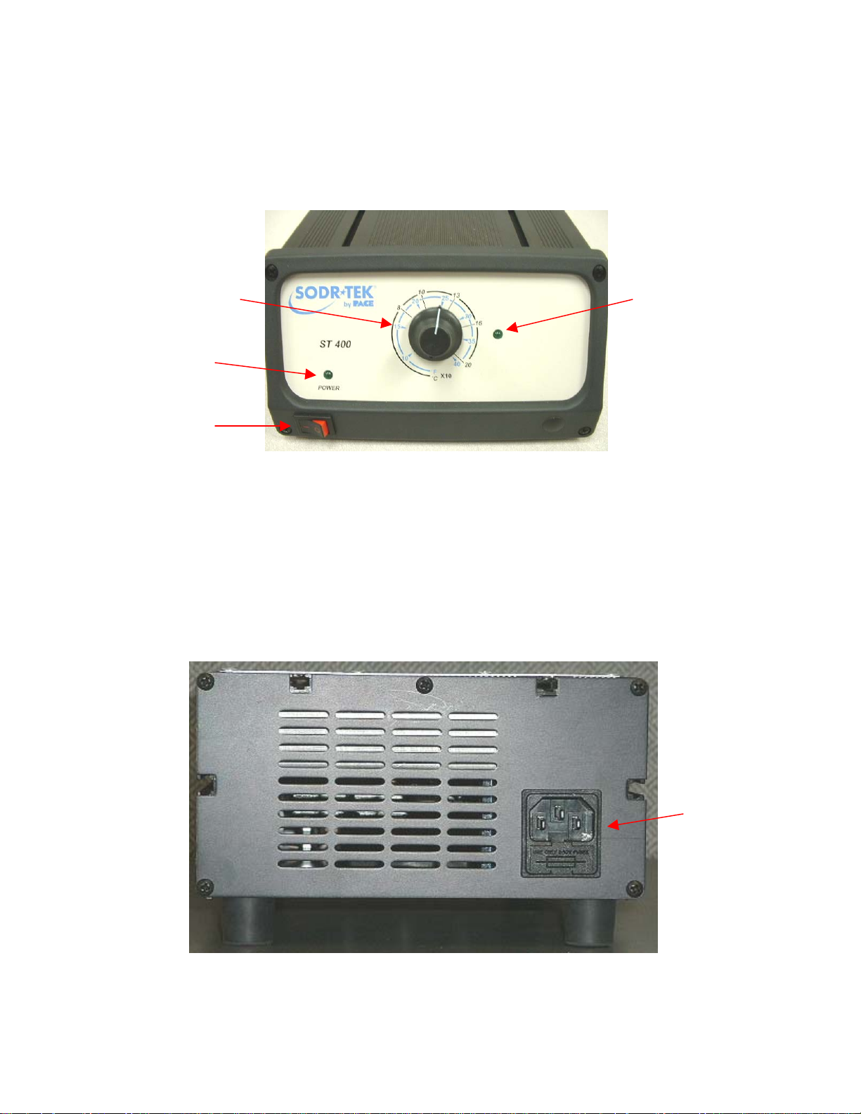
Parts Identification
Variable
Temperature
Control
Power LED
Power Switch
Temperature
Indicator LED
Figure 1
AC Power
Receptacle/Fuse
Holder
Figure 2
©2004 PACE Inc., Annapolis Junction, Maryland Page 4 of 14
All Rights Reserved
Page 5

Safety
Safety Guidelines
The following are safety precautions that personnel must understand and follow when using or
servicing this product.
1. POTENTIAL SHOCK HAZARD - Repair procedures on PACE products should be
performed by Qualified Service Personnel only. Line voltage parts may be exposed
when the equipment is disassembled. Service personnel must avoid contact with these
parts when troubleshooting the product.
2. To prevent personnel injury, adhere to safety guidelines in accordance with OSHA and
other applicable safety standards.
3. Always use PACE systems in a well ventilated area. A fume extraction system such as
those available from PACE are highly recommended to help protect personnel from
solder flux fumes.
4. Exercise proper precautions when using chemicals (e.g., solder paste). Refer to the Material
Safety Data Sheet (MSDS) supplied with each chemical and adhere to all safety precautions
recommended by the manufacturer.
5. Do not contact the Heater or its peripheral parts during operation.
6. Once turned off, let the unit cool completely before contacting.
7. After use, verify that the amber indicator lamp is off.
8. When using Fluxes, use fume extraction equipment or use in a well-ventilated area to
minimize operator exposure to fumes.
Preheating Basics
Preheating of a printed circuit assembly is normally required in the repair process whenever any one or
more of the following situations exist.
1. Epoxy glass substrate with 4 or more layers.
2. Substrate with large ground planes.
3. Substrate of ceramic, polyimide or other high heat dissipative material.
4. Printed circuit assembly with large metal heat sinks.
Preheating of assemblies such as those listed above will accomplish the following objectives.
1. Minimize thermal shock by elevating the assembly temperature to a level closer to solder melt
temperature.
2. Minimize the heat cycle reflow time.
3. Overcome the heat dissipation characteristics of the assembly.
4. Minimize adjacent melts on densely populated assemblies.
©2004 PACE Inc., Annapolis Junction, Maryland Page 5 of 14
All Rights Reserved
Page 6

The assembly undergoing repair must be heated for a length of time sufficient to saturate at the preheat
temperature required. The PCB preheat temperature normally used is 100°C (212°F) for epoxy glass
substrates and 120°C (248°F) for ceramics and polyimides.
System Power Up
1. Insert the female end of the power cord into the AC Power Receptacle on the rear panel of
the power source.
2. Plug the prong end (male end) of the power cord into an appropriate 3 wire grounded AC
supply receptacle.
CAUTION: To insure operator and ESD/EOS safety, the AC power supply receptacle must be
checked for proper grounding before initial operation.
Operation
The PACE ST 400 unit is easy to operate and can be quickly set up for operation. The following steps
provide basic guidelines for rework using the PACE ST 400.
1. Turn on the Power Switch.
a. The Green Power LED will illuminate
b. If the LED does not illuminate, refer to the Corrective
Maintenance Section of this manual.
2. Position the ST 400 under your PACE board holding
fixture. The ST 400 can be placed under any ST 525 or
ST 550 system. Be sure to follow the board installation
steps, which are detailed in the ST 500 Series Manual.
Figure 3 illustrates a typical usage. Please note that the
ST 450 is pictured in Figure 3.
Figure 3
NOTE: For best results, keep the distance between the ST 400 and the board holding fixture to
no greater than 2 ¼ “ (5.72 cm).
3. Set Temperature knob to desired setting. It will take approximately 10 minutes for the radiant
heaters to reach their set temperature and stabilize. Use of a thermo-couple is recommended to
verify actual PCB temperatures.
LED Operation
The Green colored LED (Temperature Indicator LED) on the power source
front panel indicates System Status and Power Receptacle output status
Temperature Indicator LED
(LED OFF, ON or Flashing).
LED Full On - Continuous power is being delivered to the heaters. This
condition is evident when the system is first powered up (heaters cold) or
the Variable Temperature Control setting is increased.
LED Flashing - Indicates that the set heater temperature (as set on the
Variable Temperature Control) has been reached. Power to the heaters
is cycling Off and On to maintain set temperature.
Figure 4
©2004 PACE Inc., Annapolis Junction, Maryland Page 6 of 14
All Rights Reserved
Page 7

LED Off - No power is being delivered to the heaters. This condition is evident for a short period
of time when set temperature is reached and stabilizing or if the Variable Temperature Control
setting is decreased. If the LED never
illuminates, check for a faulty heater (see Corrective
Maintenance section).
Variable Temperature Control
Adjust the Variable Temperature Control Knob to the desired temperature
setting. Notice that the control panel has an outer graphic scale denoting
temperature in °C (Celsius) and an inner graphic scale denoting temperature in
°F (Fahrenheit). These numerical scales denote the set tip temperature times
10 (e.g., “10” on the outer scale is 10 x 10 or 100°C).
Corrective Maintenance
General Maintenance
NOTE: The ST 400 should be kept clean. If flux is spilled on the heaters, the ST 400 should be
allowed to cool to room temperature and the heater panels can be wiped off with an
appropriate flux cleaner. Always unplug the ST 400 before removing the cover to clean
the Heater Panels.
Heater Replacement
Should a heater need to be replaced, please order P/N 3018-0128-P1 for the domestic (115 volt)
system or P/N 3018-0129-P1 for the export (230 volt) system from your PACE Distributor. The
following steps provide the information as to how to replace the heating panels.
Removal
1. Remove the rear panel by removing the
5 screws.
Figure 6
2. Remove the front panel and bezel by
removing the 4 screws.
Figure 7
Figure 5
©2004 PACE Inc., Annapolis Junction, Maryland Page 7 of 14
All Rights Reserved
Page 8

3. Remove the screws on the sides of the
case (one screw on each side).
Figure 8
4. Carefully lift the top from the bottom
chassis.
Figure 9
5. Remove the two large heater wires.
They are located on the board as shown
in figure 10 and 11.
Figure 10
Figure 11
©2004 PACE Inc., Annapolis Junction, Maryland Page 8 of 14
All Rights Reserved
Page 9

6. Remove the heater sensor connector from the
J5 connection on the PC board.
Figure 12
7. Remove the 4 heater mounting plate
socket hex head screws. Carefully
remove the heater assembly from the
chassis.
NOTE: Be careful when removing the
heater assembly from the
chassis as the heater wires may
be caught on other wires or
caught on the chassis.
Requires a 9/64”
hex wrench
Figure 13
8. Carefully remove the heater retaining clip. Be sure
to support the heater during this process.
Figure 14
©2004 PACE Inc., Annapolis Junction, Maryland Page 9 of 14
All Rights Reserved
Page 10

9. Pull the heater and its wires from the
heater mounting plate.
Figure 15
Installation
10. Take the new heater and insert the heater wires through the heater mounting plate and
secure the heater as shown in figure 16 and 17 and install the heater retaining clip.
Figure 16
Figure 17
11. Tighten the 4 heater retaining socket hex
head screws.
Figure 18
©2004 PACE Inc., Annapolis Junction, Maryland Page 10 of 14
All Rights Reserved
Page 11

12. Reconnect and route the wires as shown in figures 19 through 22.
Figure 19 Figure 20
Figure 21 Figure 22
NOTE: The heater has been removed in the above pictures to allow proper viewing of wire
routing.
13. Reinstall the top half of the case.
Figure 23
14. Reinstall the rear panel.
Figure 24
©2004 PACE Inc., Annapolis Junction, Maryland Page 11 of 14
All Rights Reserved
Page 12

15. Reinstall the front panel.
NOTE: The front panel screws are longer than the
side and rear panel screws.
Figure 25
16. Reconnect power and test the system.
Power Source
Refer to the table below. Most malfunctions are simple and easy to correct.
Symptom Probable Cause Solution
No power to system
Blown Fuse Replace the fuse(s) with one of the same rated
value.
Line cord
Plug line cord into the appropriate AC outlet
unplugged
Heater Assembly does
not heat.
Blown Fuse Replace the fuse(s) with one of the same rated
value.
Open Heater Replace the heater. Refer to the Heater
Replacement section on page 7.
The indicated temperature is based on 1 ½” away from the top of the system .
Packing List
Item # Description Part Number ST 400
Only
ST 400 E
Only
1 System Power Supply 8007-0435 1 0
2 System Power Supply
8007-0436 0 1
(Export)
3 Power Cord, 115V 1332-0094 1 0
4 Power Cord, 230V 1332-0093 0 1
6 Operations Manual CD CD5050-0459 1 1
Spare Parts
Item # Description PACE Part Number
Fuse, 7 Amp, 125 V, Time Lag (ST 400) 1159-0274-P5 1
Fuse, 3.15 Amp, 250 V, Time Lag (ST 400E) 1159-0221-P5
Service
Please contact PACE or your local distributor for service and repair.
©2004 PACE Inc., Annapolis Junction, Maryland Page 12 of 14
All Rights Reserved
Page 13

“SODRTEK by PACE” LIMITED WARRANTY STATEMENT
Limited Warranty
Seller warrants to the first user that products manufactured by it and supplied hereunder are free of
defects in materials and workmanship for a period of one (1) year from the date of receipt by such user.
Monitors, computers and other brand equipment supplied but not manufactured by PACE are covered
under their respective manufacturer’s warranty in lieu of this Warranty.
This warranty does not cover wear and tear under normal use, repair or replacement required as a result
of misuse, improper application, mishandling or improper storage. Consumable items such as tips,
heaters, filters, etc. which wear out under normal use are excluded. Failure to perform recommended
routine maintenance, alterations or repairs made other than in accordance with Seller’s directions, or
removal or alteration of identification markings in any way will void this warranty. This warranty is
available only to the first user, but the exclusions and limitations herein apply to all persons and entities.
SELLER MAKES NO OTHER WARRANTY, EXPRESS OR IMPLIED, AND MAKES NO WARRANTY OF
MERCHANTABILITY OR FITNESS FOR A PARTICULAR PURPOSE.
Seller will, at its option, repair or replace any defective products at its facility or other location approved by
it at no charge to user, or provide parts without charge for installation by the user in the field at user’s
expense and risk. User will be responsible for all costs of shipping equipment to Seller or other location
for warranty service.
EXCEPT FOR THE REMEDY ABOVE DESCRIBED, UNLESS OTHERWISE REQUIRED BY
APPLICABLE LAW, SELLER WILL HAVE NO OTHER OBLIGATION WITH REGARD TO ANY BREACH
OF WARRANTY OR OTHER CLAIM WITH RESPECT TO THE PRODUCTS, OR LIABILITY FOR ANY
DIRECT, INDIRECT, CONSEQUENTIAL, OR INCIDENTAL LOSS OR DAMAGE CAUSED BY OR
OCCURRING IN CONNECTION WITH ANY OF THE PRODUCTS.
Warranty service may be obtained by contacting the appropriate PACE Company or local Authorized
PACE distributor as set forth below to determine if return of any item is required, or if repairs can be made
by the user in the field. Any warranty or other claim with respect to the products must be made with
sufficient evidence of purchase and date of receipt, otherwise user’s rights under this warranty shall be
deemed waived.
For PACE USA Customers:
PACE, INCORPORATED
9030 Junction Drive
Annapolis Junction, Maryland 20701
Tel. 301-317-3588
FAX. 301-498-3252
For PACE EUROPE Customers:
PACE EUROPE LIMITED
Sherbourne House, Sherbourne Drive,
Tilbrook, Milton Keynes
MK7 8HX
United Kingdom
Tel. (44) 1908 277666
WARRANTY SERVICE FAX: (44) 1908 277 777
All other Customers:
Local Authorized PACE Distributor
©2004 PACE Inc., Annapolis Junction, Maryland Page 13 of 14
All Rights Reserved
Page 14

PACE Incorporated retains the right to make changes to specifications contained herein at any time,
without notice. Contact your local authorized PACE Distributor or PACE Incorporated to obtain the latest
specifications.
The following are trademarks and/or service marks of PACE, Incorporated, MD, USA:
INSTACAL
POWERPORT
™
, FUMEFLO™, HEATWISE™, PACEWORLDWIDE™, PERMAGROUND™,
™
, POWERMODULE™, TEMPWISE™, TIP-BRITE™, AUTO-OFF™, and
TEKLINK™.
The following are registered trademarks and/or service marks of PACE Incorporated, Annapolis Junction
Maryland U.S.A.
ARM-EVAC
SODRTEK
VISIFILTER
®
, FLO-D-SODR®, MINIWAVE®, PACE®, SENSATEMP®, SNAP-VAC®,
®
, SODR-X-TRACTOR®, ST 400®, THERMOJET®, THERMOTWEEZ®,
®
, THERMO-DRIVE®, and TOOLNET®.
PACE products meet or exceed all applicable military and civilian EOS/ESD, temperature stability and
other specifications including MIL STD 2000, ANSI/JSTD 001, IPC7711, and IPC A-610.
www.paceworldwide.com
PACE USA PACE Europe
9030 Junction Drive Sherbourne House
Annapolis Junction, MD 20701 Sherbourne Drive
USA Tilbrook, Milton Keynes
MK7 8HX
United Kingdom
Tel: (301) 490-9860 (44) 01908-277666
Fax: (301) 498-3252 (44) 01908-277777
©2004 PACE Inc., Annapolis Junction, Maryland Page 14 of 14
All Rights Reserved
 Loading...