

Page 1
ST325 / ST350 & ST350 Rework Station
Software Operation Manual
Manual Number 5050-0546 Rev 3-05-tf
Page 2

ST 325 / ST350 Software Operations Manual
Table of Contents
System Requirements ........................................................................3
Safety Guidelines................................................................................3
Usage Warnings / Cautions................................................................3
Features..............................................................................................4
Software installation............................................................................4
Connecting the ST325 / ST350 to your PC.........................................5
Main Screen Controls..........................................................................5
File Menu ...............................................................................5
Link Menu...............................................................................6
Help Menu..............................................................................7
Profile Parameters Tab “Timed Profile”.................................8
Manage Profiles Tab “Timed Profile”.....................................9
Run Cycle Tab “Timed Profile” ...........................................10
Profile Parameters Tab “Zoned Profile”...............................11
Manage Profiles Tab “Zoned Profile”...................................12
Run Cycle Tab “Zoned Profile”............................................13
The Temperature Graph......................................................14
Profile Creation.................................................................................15
Ramp and Maximum Temperatures ................................... 15
Pre-Heat Phase...................................................................15
Soak Phase ........................................................................15
Reflow Phase.......................................................................15
Cool Down Phase ...............................................................16
Profile Log ...........................................................................16
Profile Creation using the clipboard feature .....................................17
Regulation.........................................................................................18
Service and Warranty.......................................................................18
Contact Information ..........................................................................19
www.paceworldwide.com
Page 2 of 19
Page 3

ST 325 / ST350 Software Operations Manual
System Requirements
PACE Software Part Number 5050-0546
PC Requirements Pentium 4, 256M Ram, Floppy, CD
Safety Guidelines
The following are safety precautions that personnel must understand and follow when using or
servicing this product.
“NOTE”
Used to indicate a statement of company recommendation or policy. The message may relate
directly or indirectly to the safety of personnel or protection of property. NOTE is not associated
directly with a hazard or hazardous situation and is not used in place of "CAUTION", "WARNING"
or "DANGER".
“CAUTION”
Used to indicate a hazardous situation, which may result in minor or moderate injury. May also be
used to alert personnel to conditions, procedures and practices which, if not observed, could
result in damage to or destruction of the product or other equipment.
“WARNING”
Used to define additional information that if not closely followed might result in serious damage to
equipment and represent a potential for serious personnel injury.
“DANGER”
Defines additional information that if not closely followed might result in severe personnel injury or
death. Danger is not used for property damage unless personal injury risk is present.
Usage Warnings/Cautions
WARNINGS
1. A fire hazard may arise if the ST325 is used improperly.
2. Do not use the ST325 in the presence of an explosive atmosphere.
3. Be careful when using the ST325 in places where there are combustible materials. Heat may
be conducted to combustible materials that are not in sight.
4. Do not apply heat from the ST325 to one place for a long time.
5. Do not leave the ST325 unattended while powered on.
www.paceworldwide.com
Page 3 of 19
Page 4

CAUTIONS
1. The ST325 handpiece heater assembly housing and any installed nozzle are hot when the
system is being cycled and for a period of time thereafter. DO NOT touch the heater
assembly housing, nozzle or direct heated air stream. Severe burns may result!
2. Utilize all standard electrical safety precautions when using this or any other electrical
equipment.
3. Always use the ST325 with the Heat Shield installed. The Heat Shield helps to prevent
unintentional contact with the heater.
4. Always use this system in a well-ventilated area. A fume extraction system such as those
available from PACE are highly recommended to protect personnel from solder flux fumes.
5. Exercise proper precautions when using chemicals (e.g., solder paste). Refer to the Material
Safety Data Sheet (MSDS) supplied with each chemical and adhere to all safety precautions
recommended by the manufacturer.
Features
The ST325 is ideal for post assembly rework, repair, and low volume/short run production
operations. The ST-325’s dynamic software will store criteria to remove and install PBGAs,
CSPs, FCs, LGAs, LCC’s and other SMDs.
Featuring unparalleled thermal performance, the ST 325’s flexibility and state of the art process
software means no other system is easier to use. The ST 325 requires a Pentium ® 4 PC
featuring Windows XP® Professional Operating System.
Software Installation
ST 325 / ST350 Software Operations Manual
1 Rev 1.22 or higher firmware is required to work with the ST 325 / 350 PC software. The
firmware revision is displayed on the front panel when the unit is turned on.
2 Look at the specifications in section 1 on page 3 and ensure that the computer you
choose is suitable.
3 Ensure that you have installation rights on the computer, and that none of the drives on
which you will load PACE ST325 / ST350 Software (A: and hard drives such as C: or D:)
are shared in any way, or locked by a virus checker.
4 Put the PACE ST325 / ST350 CD into the CD drive.
5 Wait for instructions to appear on the screen, and follow them. (If no instructions appear,
find the CD drive containing the PACE ST325 / ST350 CD using My Computer or Explorer.
Then open the CD directory, and double-click on setup or setup.exe).
www.paceworldwide.com
Page 4 of 19
Page 5
ST 325 / ST350 Software Operations Manual
Connecting the ST325 / ST350 to your PC
Your personal computer communicates to the ST325 or ST350 through the RS-232 (9 pin )
connection located on the back of the ST325 / ST350. Before connecting, make sure cable and
panel connections are clean and straight. Do not over tighten cable connection. From the “lin k”
menu, select a COM port to connect the ST325 / ST350.
Main Screen Controls
When creating a profile the operator may select from two profile types. The “timed” profile limits
the profile controls to applying heat to the nozzle for a specific temperature and time duration.
The “zoned” profile will control temperature and time durations for three independent zo nes that
consist of the pre-heat, soak, and reflow. Each zone may be customized to fit the component
requirement for installation or removal. Please see page 15 for instructions on creating a zoned
profile.
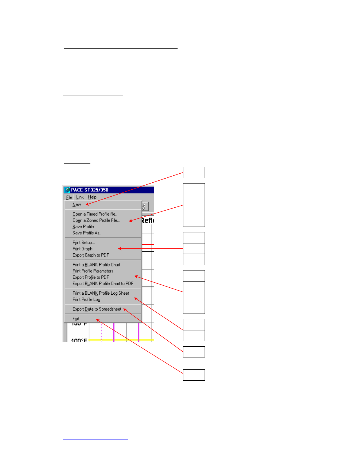
File Menu
i. New.
ii. Open a Timed Profile file.
iii. Open a Zoned Profile file.
iv. Save Profile.
v. Save Profile As.
vi. Print Setup.
vii. Print Graph.
viii. Export Graph to PDF
ix. Print a BLANK Profile Log
Sheet.
x. Print Profile Parameters
xi. Export Profile to PDF
xii. Export BLANK Profile Chart
to PDF
xiii. Print a Blank Profile Log
Sheet
xiv. Print Profile Log
xv. Export Data to Spreadsheet
xvi. Exit
www.paceworldwide.com
Page 5 of 19
Page 6
ST 325 / ST350 Software Operations Manual
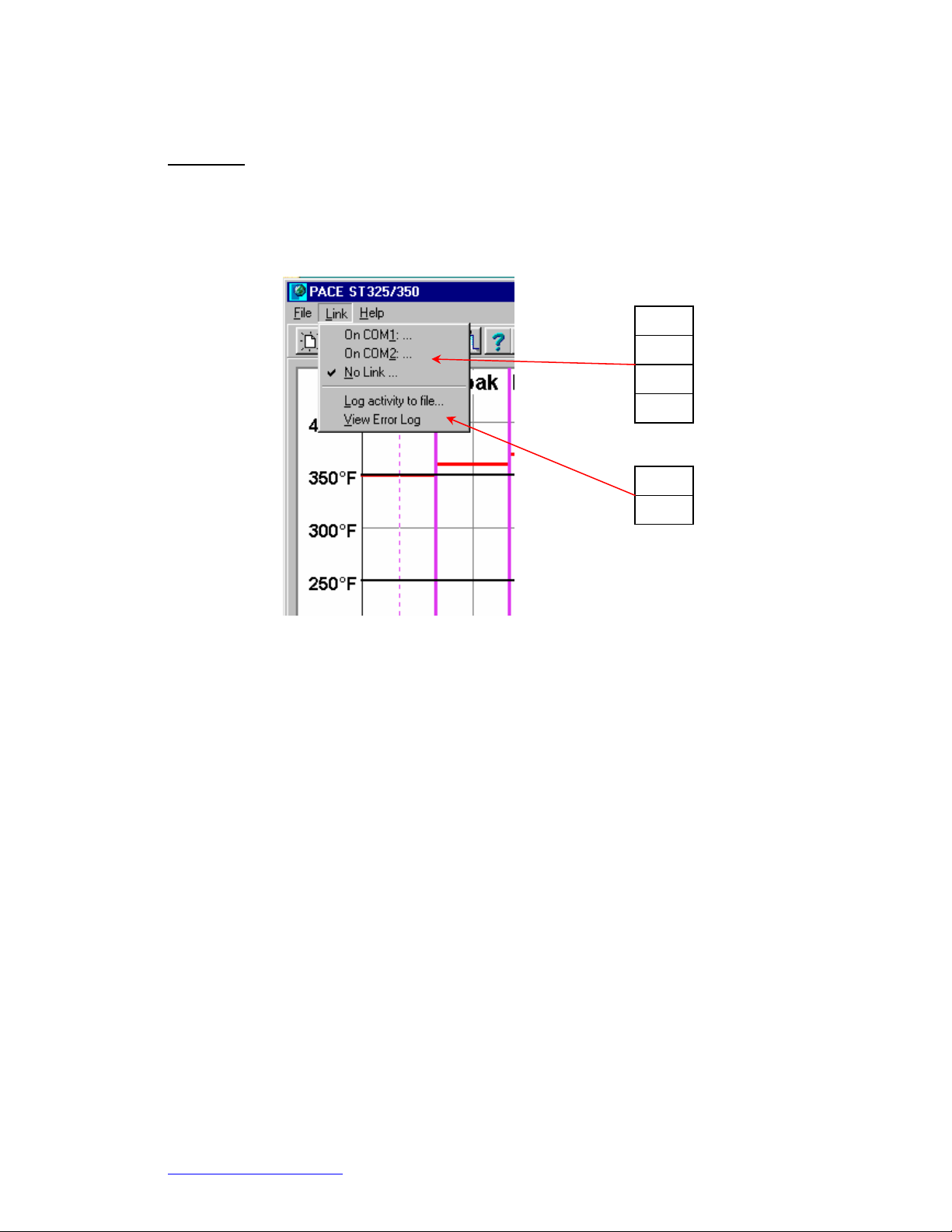
Link Menu
Clicking on the link menu will reveal the options to connect your PC to the PACE unit. It is
important to select an active COM port before attempting to save profiles to the ST325 or ST
350.
i. COM 1
ii. COM 2
iii. COM 3
iv. No Link.
v. Log activity to file
vi. View Error Log
www.paceworldwide.com
Page 6 of 19
Page 7

ST 325 / ST350 Software Operations Manual
Help Menu
The Help Menu drop down box contains links to the software and hardware manuals in PDF
form. Please read and understand all safely instructions before operating the PACE ST325 or
ST350.
i. View ST325 Software Manual.
ii. View ST325 Software Manual.
iii. View ST350 Software Manual.
iv. About.
www.paceworldwide.com
Page 7 of 19
Page 8

ST 325 / ST350 Software Operations Manual
Profile Parameters Tab “Timed”
The Timed Profile menu allows the operator to create and save profiles that are time driven.
Settings are changed by use of the drop down menus to the right of the graph window. The graph
window is also interactive. The operator may increase or decrease temperature settings by using
the cursor to click and drag the horizontal bar. The vertical time bar may also be adjusted by click
and dragging with cursor.
i. Timed Profile. Indicates currently selected profile.
ii. Title. Use defined name given to profile.
iii. Profile name assigned by profile developer will be shown here.
iv. Scale. Drop down box for selecting Fahrenheit of Celsius scale.
v. Process. Drop down box for selecting install or removal.
vi. Time, Sec. Temps. Sets temperature at nozzle.
vii.
Blower. Scroll box that sets blower speed. (1-9)
www.paceworldwide.com
Page 8 of 19
Page 9

ST 325 / ST350 Software Operations Manual
Manage Profiles Tab “Timed”
The Manage Profile menu gives the operator the ability to load, save, and export profiles. This
menu will also allow the operator to store and retrieve profiles from the ST325. The ST325 /
ST325 hardware is capable of storing 20 zoned profiles and 20 timed profiles and the PC
software will manage all saved profiles. Profiles are easily exported to PDF file format. Accessing
the profile log will show all of the saved profiles within the ST325 / ST350.
i. Load a timed profile from File.
ii. Load a Zoned Profile from File.
iii. Save Profile to File. Saves current profile.
iv. Store Profile in ST325 / ST350. Saves current profile to ST325 / ST350
v. Retrieve Profile from ST325 / ST350.
vi. Print Profile Parameters. Sends current profile to selected printer.
vii. Export Params to PDF. Saves current profile to Adobe PDF file.
viii.
View Profile Log. Opens profile log stored within the ST325 / ST350
software.
www.paceworldwide.com
Page 9 of 19
Page 10

ST 325 / ST350 Software Operations Manual
Run Cycle Tab “Timed “
The Run Cycle executes the selected or newly developed profile. At any time the operator may
choose to abort the profile and return the to the ready mode. The operator may also choose to
export the selected profile to a spreadsheet the “Export Data to Spreadsheet ” button creates a
Comma Separated Value (CSV) file that can be opened by any standard spreadsheet software.
The “Print Graph” button will send the current record to the selected printer. The “Export Graph to
PDF” button created a (PDF) file of the record on the PC hard drive. Password Protection allows
the operator to “lock out” other users.
i. RUN Temperature Cycle. Starts profile.
ii. ABORT Temperature Cycle.
iii. Export Data To Spreadsheet.
iv. Print Graph. Export Graph to PDF.
v. Export Date To Spreadsheet.
vi. Print Graph.
vii. Export Graph To PDF.
viii. Password Protection.
www.paceworldwide.com
Page 10 of 19
Page 11

ST 325 / ST350 Software Operations Manual
Profile Parameters Tab “Zoned Profile”
The profile parameters menu allows the operator to set and control all aspects of the profile cycle.
In addition to the menu controls, using the cursor to click and drag the vertical and horizontal bars
in the process graph will also change settings. By selecting the “Use lower Temp. Prompt”
feature, the user is prompted to set the manual temperature control for an optional under board
heater. See section 12, Profile Creation “step profile” for detailed information on zone and
temperature settings.
ii. Title. Profile name assigned by profile developer will be shown here.
iii. Scale. Drop down box for selecting Fahrenheit of Celsius scale.
iv. Process. Drop down box for selecting install or removal.
v. Use Lower Temp. Prompt? Prompt user to set temp on optional under board heater.
vi. Preheat Zone. Set preheat time and temperature limit.
vii. Soak Zone. Set soak time and temperature limit.
viii. Reflow Zone. Set reflow time and temperature limit.
ix. Use Cool down?
x. Process graph. Display of profile setting.
i. Zoned profile. Indicates currently selected profile.
www.paceworldwide.com
Page 11 of 19
Page 12

ST 325 / ST350 Software Operations Manual
Manage Profile Tab “Zone Profile”
The “Manage Profile” menu gives the operator the ability to load, saves, and export profiles. This
menu will also allow the operator to store and retrieve profiles from the ST325 or ST350. The ST
325 and ST350 are capable of storing up to 20 profiles. The ST325 / ST350 software has the
capacity of storing 40 profiles with a single profile set. Multiple set maybe stored on the PC for
later use. Profiles are easily exported to PDF file format. Accessing the profile log(s) will show all
of the saved profiles.
i. Load a timed profile from File.
ii. Load a Zoned Profile from File.
iii. Save Profile to File. Saves current profile.
iv. Store Profile in ST325 / ST350. Saves current profile to ST325 / ST350.
v. Retrieve Profile from ST325 / ST350.
vi. Print Profile Parameters. Sends current profile to selected printer.
vii. Export Params to PDF. Saves current profile to Adobe PDF file.
viii.
View Profile Log.
www.paceworldwide.com
Page 12 of 19
Page 13

ST 325 / ST350 Software Operations Manual
Run Cycle Tab “Zone Profile”
The Run Cycle executes the selected or newly developed profile. At any time the operator may
choose to abort the profile and return the ST325 / ST350 to the ready mode. The operator may
also choose to export the selected profile to a spreadsheet. The “Export Data to Spreadsheet ”
button creates a Comma Separated Value (CSV) file that can be opened by any standard
spreadsheet software. The “Print Graph” button will send the current record to the selected
printer. The “Export Graph to PDF” button created a (PDF) file of the record on the PC hard drive.
Password Protection allows the operator to “lock out” other users.
ix. RUN Temperature Cycle. Starts profile.
x. ABORT Temperature Cycle.
xi. Export Data To Spreadsheet.
xii. Print Graph. Export Graph to PDF.
xiii. Export Date To Spreadsheet.
xiv. Print Graph.
xv. Export Graph To PDF.
xvi. Password Protection
www.paceworldwide.com
Page 13 of 19
Page 14

ST 325 / ST350 Software Operations Manual
The Temperature Graph
During profile creation, the operator can adjust most time and temperature settings by dragging
the vertical or horizontal bars within the temperature graph. During the run cycle, the graph will
plot the temperature setting throughout the cycle. As the cycle advances, the operator can hover
the cursor over the moving indicator line to reveal the temperature at that point in the cycle.
i. Preheat. Show time duration of cycle.
ii. Soak.
iii. Reflow.
iv. Cool down.
v. Time indi cator and adjustment bar
vi. Time scale in minutes
vii. Blower speed
viii. Temperature indicator and adjustment bar
ix. Temperature scale
www.paceworldwide.com
Page 14 of 19
Page 15

ST 325 / ST350 Software Operations Manual
Profile Creation
There are 2 recommended methods for developing a profile. The first, involves an actual
component installation, while the second uses a previously installed package. Either method can
be used to develop a reliable profile. However, there are some issues and considerations to be
aware of with each.
When developing profiles through actual component installation, it is critical to make sure the
thermocouples remain in contact with the solder throughout the entire process. Unreliable data
will be collected should a thermocouple lose contact with the solder.
When using a previously installed package, the placement of the thermocouples is important.
They must be in contact with the existing solder joints. This task can be accomplished by either
(1) drilling through the bottom of the PCB into a solder joint and attaching the thermocouple or by
(2) sliding the thermocouple under the package in the case of a BGA or along sid e in the case of
other SMD’s. When sliding a thermo couple under a component, it is critical that the
thermocouple be in contact with the solder. Method 2 is the most commonly used. Information
from the thermocouples will assist in determining the proper time and temperature parameters. In
general, the following guidelines should be adhered to when developing profiles.
Ramp and Maximum Temperatures
Acceptable ramp rates and maximum temperatures should be obtained from the component
manufacturer. Typical ramp rates are 2-5 ºC/s (4-9 ºF/s) for plastic parts and 1 ºC/s (2 ºF/s) for
ceramic parts. It is recommended to select a maximum temperature below the manufacturer’s
specification to provide for a margin of safety. Typically, 20 ºC below maximum specified
temperature is selected.
Pre-Heat Phase
In a “ST325 / ST350 profile,” the top of the PCB and package should reach a stable temperature
of 95-105 ºC. When plotting the temperature curve, the trace will usually level off within this
temperature range. If a “linear slope” is desired, pre-heat and soak phases are combined. Both
the package and the PCB are warmed at a constant ramp rate (usually 2-4 ºC/second) until the
desired soak temperature is reached.
Soak Phase
The soak phase is a crucial part of the reflow process. During this period, the flux activates and
drives off volatiles and excess flux. A temperature of 145-165 ºC (determined by the activation
temperature of the flux used) should be maintained for approximately 20-40 seconds. This
allows for uniform ramping across the entire package and PCB during reflow.
Reflow Phase
During this phase, the solder reaches solder melt and forms joints between the package and the
lands. It is critical for all areas of the component to reach solder melt together and all solder
joints remain in a liquid state for at least 10-20 seconds. Generally, plastic packages sho uld not
be exposed to temperatures higher than 220 ºC. Always consult the device specifications for
maximum temperature recommendations. As a rule of thumb, a safe “maximum temperature” is
the maximum temp specified by the manufacturer minus 20ºC. Lower temperatures and shorter
times are common in CSPs and FCs. The lowest temperatures possible should always be
used to ensure safety of the device and PCB.
www.paceworldwide.com
Page 15 of 19
Page 16

ST 325 / ST350 Software Operations Manual
Cool Down Phase
The cool down phase is necessary to bring the temperature of the package, solder joints and
PCB under the package below solder melt temperatures. Cooling should be controlled. A good
reference is to use the same cool down rate as for ramp up.
General
Using one of the two baseline (default) profiles will provide a good starting point for profile
development. The reflow graph provides an excellent tool for monitoring profile parameters and
fine tuning or perfecting the profile development process. When adjusting profile parameters “onthe-fly,” all changes are reflected immediately on the profile development screen and graph.
Parameters may not be changed while profile is running. Operator must “abort” the run cycle
before modifying the profile.
Profile Log
When saving a profile, the user will be prompted to select a profile number. Selecting a number
that contains an existing profile will over write the previous profile. While viewing the profile log,
the operator may open the profile setting menu by clicking anywhere within the profile row. The
“Load Profile Set” is a complete set of all the profiles that are saved on the PC hard drive. This is
a simple way to load all 40 profiles at once. The Save Profile Set button will open a save window
allowing the operator to save the current profile set or rename saving an additional set of forty
profiles.
The profile log is also interactive. The user may edit the parameters of a stored profile by right
clicking on the selected profile to open the pop up menu shown below. If you want to run the
profile you just changed, you will need to select the “make this the current profile” from the right
click pop up menu.
www.paceworldwide.com
Page 16 of 19
Page 17

ST 325 / ST350 Software Operations Manual
Profile Creation using the clipboard feature.
A quick and efficient way of creating a profile is to use the clipboard feature. Here are the steps
necessary to create a new profile from and existing one.
1) Select a stored profile by clicking on its line in the Profile Log.
2) Copy the stored profile to the clipboard. Either:
a) Right click, and select the "Copy this profile to clipboard" menu item,
OR
b) Just type control-C to copy the selected line in the Profile Log.
3) Click on a new line in the Profile Log, where you want to paste the profile.
4) Paste the profile from the clipboard to that new line in the Profile Log. Either:
a) Right click, and select the "{Paste profile" menu item,
OR
b) Just type control-V to copy the selected line in the Profile Log.
5) A copy of the profile has now been pasted to the selected line in the Profile Log. Just double-
click on this line to bring up the edit window, and change the profile's parameters as desired.
Profile setting menu
By selecting the “Edit this profile” the
user is able to adjust all aspects of
the selected profile.
www.paceworldwide.com
Page 17 of 19
Page 18

ST 325 / ST350 Software Operations Manual
www.paceworldwide.com
PACE USA PACE Europe
9030 Junction Drive Sherbourne House
Annapolis Junction, MD 20701 Sherbourne Drive
USA Tilbrook, Milton Keynes
MK7 8HX
United Kingdom
Tel: (301) 490-9860 (44) 1908-277666
Fax: (301) 498-3252 (44) 1908-277777
PACE Incorporated retains the right to make changes to specifications contained herein at any time,
without notice. Contact your local authorized PACE Distributor or PACE Incorporated to obtain the latest
specifications.
The following are trademarks and/or service marks of PACE, Incorporated, MD, USA:
INSTACAL
POWERPORT
™
, FUMEFLO™, HEATWISE™, PACEWORLDWIDE™, PERMAGROUND™,
™
, POWERMODULE™, TEMPWISE™, TIP-BRITE™, AUTO-OFF™, and
TEKLINK™.
The following are registered trademarks and/or service marks of PACE Incorporated, Annapolis Junction
Maryland U.S.A.
ARM-EVAC
SODRTEK
VISIFILTER
®
, FLO-D-SODR®, MINIWAVE®, PACE®, SENSATEMP®, SNAP-VAC®,
®
, SODR-X-TRACTOR®, THERMOFLO®, THERMOJET®, THERMOTWEEZ®,
®
, THERMO-DRIVE®, and TOOLNET®.
PACE products meet or exceed all applicable military and civilian EOS/ESD, temperature stability and other
specifications including MIL STD 2000, ANSI/JSTD 001, IPC7711, and IPC A-610.
www.paceworldwide.com
Page 19 of 19
 Loading...