

PACE ST 325 Service Manual
Operation and Maintenance Manual for the
SODRTEK
ST 325 Digital Convective
®
Soldering/Desoldering System
P/N 5050-0537

TITLE PAGE
General Information .......................................................................................................3
Introduction...........................................................................................................3
Microprocessor Control........................................................................................3
ST 350 Precision Reflow Head............................................................................3
Specifications .......................................................................................................3
Parts Identification................................................................................................5
Safety.............................................................................................................................7
Safety Guidelines.................................................................................................7
Usage Warnings/Cautions....................................................................................7
Servicing Precautions...........................................................................................8
System Set-Up...............................................................................................................8
Setup....................................................................................................................8
Vacuum Pick ........................................................................................................8
Handpiece Stand..................................................................................................9
Quickfit Nozzle Adapter........................................................................................9
Nozzle Selection..................................................................................................10
Nozzle Changeout.........................................................................................................11
Removal ..............................................................................................................11
Installation ...........................................................................................................11
Definitions......................................................................................................................11
System Power Up .........................................................................................................12
Set Up Mode.................................................................................................................12
Automatic Calibration....................................................................................................13
Operation.......................................................................................................................14
Password.............................................................................................................14
Front Panel Selections........................................................................................14
Pik-Vak Operation ...............................................................................................15
Component Removal; Manual Mode...................................................................15
Component Installation; Manual Mode................................................................17
Timed Removal...................................................................................................19
Timed Install........................................................................................................20
PC Control.....................................................................................................................23
Memory................................................................................................................23
Save ....................................................................................................................23
Recall...................................................................................................................23
Process Development...................................................................................................24
Profile Development............................................................................................24
General Process Guidelines .........................................................................................27
Board Preparation...............................................................................................27
Component Positioning.......................................................................................28
Preheating...........................................................................................................28
Corrective Maintenance................................................................................................29
Display Error Messages......................................................................................29
Power Source/Handpiece....................................................................................29
Packing List...................................................................................................................30
Spare Parts...................................................................................................................30
Service ..........................................................................................................................30
“SODRTEK by PACE” LIMITED WARRANTY STATEMENT.......................................31
Contact Us.....................................................................................................................32
©2004 PACE Inc., Annapolis Junction, Maryland Page 2 of 32
All Rights Reserved

General Information
Introduction
Thank you for purchasing the PACE SODRTEK
®
model ST 325 Analog Convective
Soldering/Desoldering System. This manual will provide you with the information necessary to
properly set up, operate, and maintain the ST 325. Please read this manual thoroughly before using
the unit. The ST 325 unit is a complete system designed for hot air removal and installation of SMD
components, including Ball Grid Arrays (BGAs). The following key features allow process controlled
placement and reflow of BGAs and SMD components. The ST 325 will store up to 20 profiles on its
own. A PC can be used to store additional profiles and to collect the thermocouple data.
Microprocessor Control
The microprocessor system offers precision control of temperature (closed-loop control), cycle time
(adjustable by one second increments), and blower speed provides consistent, repeatable results in
successive reflow operations. Utilizing the Quiet Flo (low noise) turbine blower, pressure/flow rate is
easily controlled and maintained at optimum levels for the particular task. A multi-level password
lock-out prevents unauthorized changes and an audible countdo wn timer indicates end of cycle.
ST 325 Handpiece
The user-friendly ST 325 static-safe handpiece incorporates a powerful heater and has easy-access
heat cycle and vacuum pick switches on the handle. A built-in, self-adjusting vacuum pick has a pushpull action, allowing components to be lifted automatically after solder reflow. When utilized with the
ST 325 System work platform, the handpiece is easily converted to a precision reflow head.
The ST 325 unit is available in either the 115 VAC or 230 VAC version. The 115 VAC version system
bears the FCC Conformity Marking which assures the user that it conforms to all the requirements of
FCC Emission Control Standard, Title 47, Subpart B, Class A. This standard is designed to provide
reasonable protection against harmful interference when the equipment is operated in a commercial
environment. The 230 VAC version system bears the CE Conformity Marking which assures the user
that it conforms to all the requirements of (EU) directive EMC 89/336/EEC & 73/23/EEC.
Specifications
ST 325 - Operates on 97-127 VAC, 60 Hz (115 VAC version)
575 Watts maximum at 120 VAC, 60 Hz
ST 325E - Operates on 197-264 VAC, 50 Hz (230 VAC version)
575 Watts maximum at 230 VAC, 50 Hz
Air Temperature Range - 149°C - 482°C (300°F - 900°F)
Timing Control - 10 to 999 seconds with 1 second resolution. (does not include preheat time)
Blower Air Flow Rate (measured at heater) - 20 SLPM (0.7 SCFM) minimum at highest speed (9).
- 5 SLPM (0.18 SCFM) minimum at lowest speed (1).
Vacuum (at Pik-Vac Port) - 7.6 cm Hg. (3 in. Hg.) minimum.
NOTE: The ST 325 is designed for cyclical usage. Attempts to use in continuous operations by
taping the handpiece Cycle Switch or other methods may void Blower Assembly warranty.
Component Capacity - (maximum size) - 5.1 cm x 5.1 cm (2” x 2”)
©2004 PACE Inc., Annapolis Junction, Maryland Page 3 of 32
All Rights Reserved

Physical Parameters
Size - 133 mm H x 260 mm W x 248 mm D (5.25” H x 10.25” W x 9.75” D)
Unit Weight - 4.3 Kg. (9.5 lbs.)
©2004 PACE Inc., Annapolis Junction, Maryland Page 4 of 32
All Rights Reserved
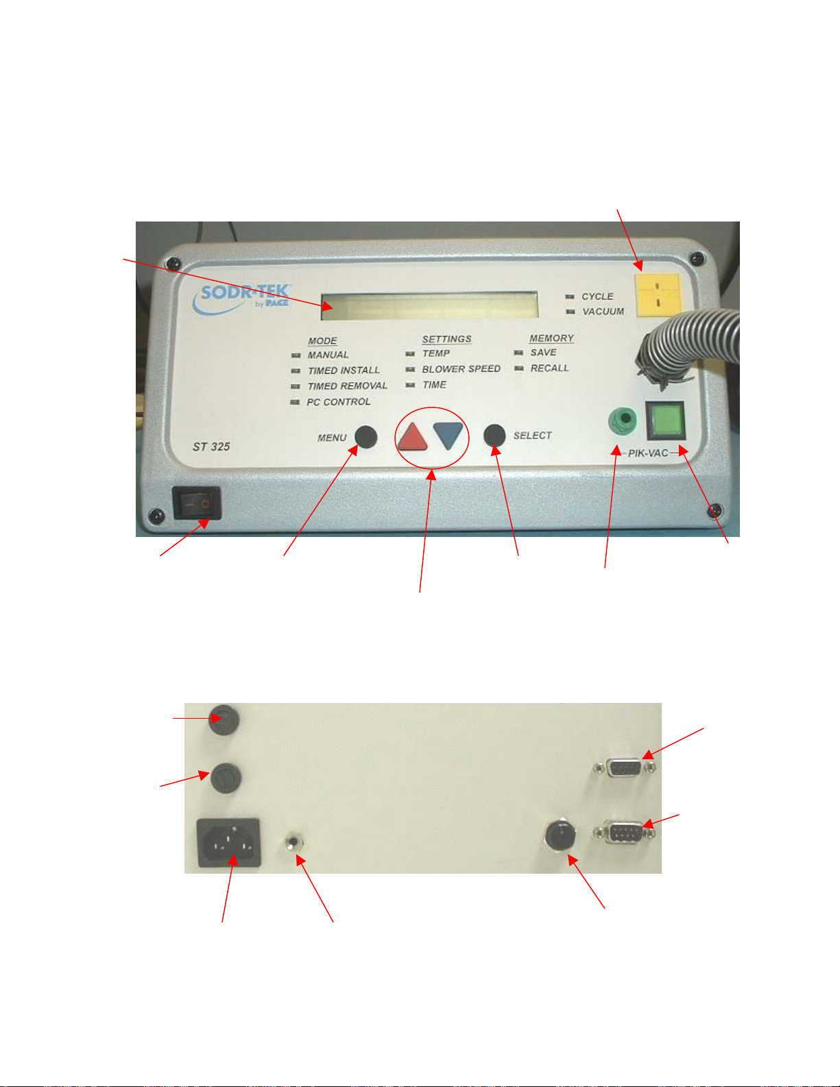
Parts Identification
LCD
Display
Power Switch
Fuse
Fuse
AC Power Receptacle Earth Ground Receptacle
Menu Key
Scroll Keys
Select Key
Pre-Heater Receptacle
K-type
Thermocouple
Receptacle
LoFlo Vacuum
Port
(ST 450)
LoFlo Pump
Switch
RS 232 PC Input
Remote Controller
Receptacle
©2004 PACE Inc., Annapolis Junction, Maryland Page 5 of 32
All Rights Reserved
r
r
r
f
r
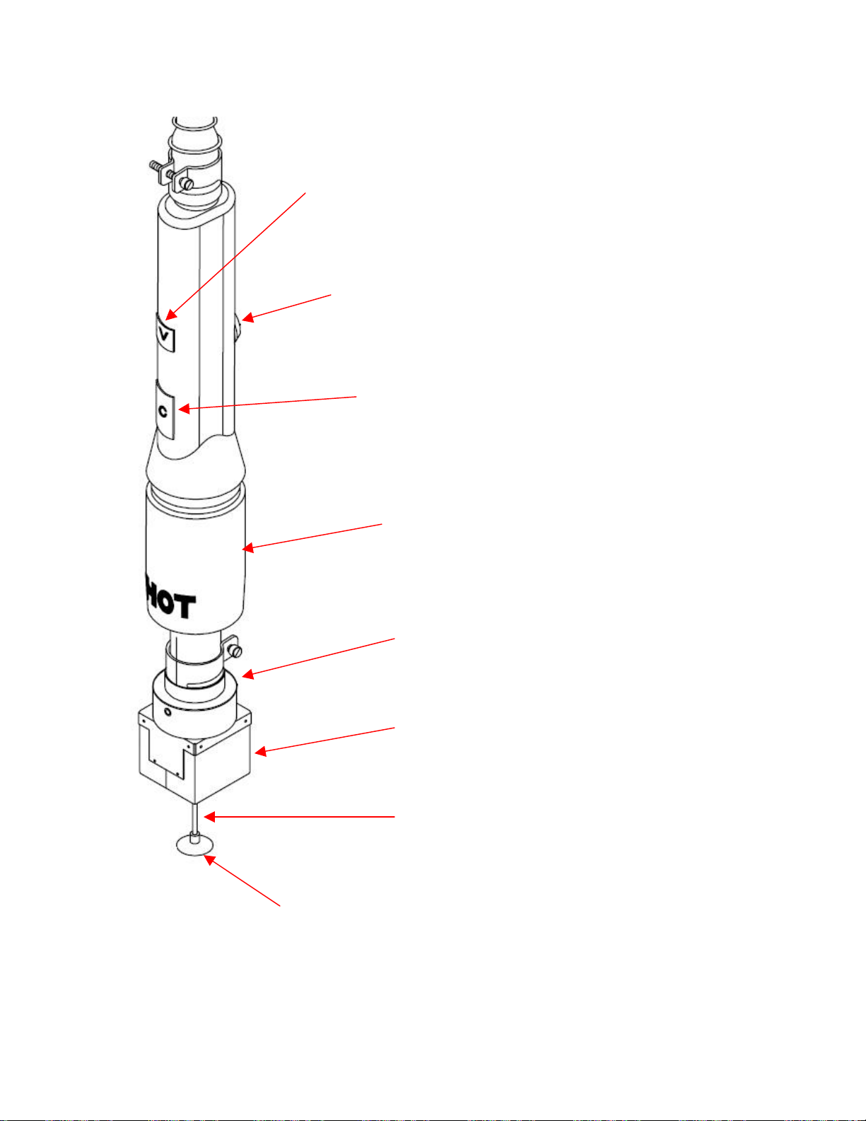
Vacuum Pick Switch - Activates & deactivates vacuum pump supply to
the Vacuum Pick Assembly. Switch must be depressed for a period o
0.5 second before circuit deactivation; activation is immediate.
VACUUM PICK ADJUST CONTROL – Provides adjustment fo
height of Vacuum Pick Assembly (& Vacuum Cup). Turn clockwise to
raise pick or counterclockwise to lower pick.
CYCLE SWITCH - Activates reflow cycle (heat & airflow). Switch
must be held to maintain activation in Manual Mode; in Timed &
Program Modes, switch is pressed & released to initiate set cycle
time. Switch can be used to abort cycle in Timed or Program
Mode operation.
HEAT SHIELD-Protects the operator from unintentional
contact with the heater.
QUICKFIT NOZZLE ADAPTER - Allows quick nozzle
attachment and release.
NOZZLE ASSEMBLY - Directs heated air from the heate
assembly to the solder joint areas for soldering o
desoldering of components. Nozzles are optional parts
ordered for a specific application.
VACUUM PICK ASSEMBLY - Provides a means to lift o
place components.
VACUUM CUP - Provides positive holding of components for positioning
during the replacement process and for lifting of the component during the
removal process.
©2004 PACE Inc., Annapolis Junction, Maryland Page 6 of 32
All Rights Reserved

Safety
Safety Guidelines
The following are safety precautions that personnel must understand and follow when using or
servicing this product.
“NOTE”
Used to indicate a statement of company recommendation or policy. The message may relate
directly or indirectly to the safety of personnel or protection of property. NOTE is not associated
directly with a hazard or hazardous situation and is not used in place of "CAUTION", "WARNING"
or "DANGER".
“CAUTION”
Used to indicate a hazardous situation, which may result in minor or moderate injury. May also be
used to alert personnel to conditions, procedures and practices which, if not observed, could
result in damage to or destruction of the product or other equipment.
“WARNING”
Used to define additional information that if not closely followed might result in serious damage to
equipment and represent a potential for serious personnel injury.
“DANGER”
Defines additional information that if not closely followed might result in severe personnel injury or
death. Danger is not used for property damage unless personal injury risk is present.
Usage Warnings/Cautions
WARNINGS
1. A fire hazard may arise if the ST 325 is used improperly.
2. Do not use the ST 325 in the presence of an explosive atmosphere.
3. Be careful when using the ST 325 in places where there are combustible materials. Heat
may be conducted to combustible materials which are out of sight.
4. Do not apply heat from the ST 325 to one place for a long time.
5. Do not leave the ST 325 unattended while powered on.
CAUTIONS
1. The ST 325 handpiece heater assembly housing and any installed nozzle are hot when
the system is being cycled and for a period of time thereafter. DO NOT touch either the
heater assembly housing, nozzle or direct heated air stream. Severe burns may result!
2. Utilize all standard electrical safety precautions when using this or any other electrical
equipment.
©2004 PACE Inc., Annapolis Junction, Maryland Page 7 of 32
All Rights Reserved

3. Always use the ST 325 with the Heat Shield installed. The Heat Shield helps to prevent
unintentional contact with the heater.
4. Always use this system in a well-ventilated area. A fume extraction system such as those
available from PACE are highly recommended to protect personnel from solder flux
fumes.
4. Exercise proper precautions when using chemicals (e.g., solder paste). Refer to the
Material Safety Data Sheet (MSDS) supplied with each chemical and adhere to all safety
precautions recommended by the manufacturer.
Servicing Precautions
DANGERS
POTENTIAL SHOCK HAZARD - Repair procedures performed on this product should be
performed by qualified service personnel only. Line voltage parts will be exposed when
equipment is disassembled. Service personnel must avoid contact with these parts when
troubleshooting.
Precautions
The following are general safety precautions which personnel must understa nd and follow when
using or servicing this product. These precautions may or may not be included elsewhere in this
manual.
Safety
Electrical Requirements
The ST 325 unit draws approximately 575 Watts, which is listed on the nameplate on the
power source rear panel. A separate, dedicated AC supply line circuit may be required to
adequately power the unit/system. If your power outlet cannot provide suitable power,
arrange for a qualified, licensed electrician to install one for you.
System Set-Up
Set up the ST 325 system using the following steps and associated drawings.
1. Remove the ST 325 from its shipping container(s). Store the shipping container(s) in a
convenient location. Reuse of these containers will prevent damage if you ship or store the
system.
2. Set the ST 325 unit on a convenient workbench.
3. Place the POWER Switch (on power source front panel) in the "OFF" or "0"
position.
4. Inspect all system components to check for shipping damage and to ensure that all
purchased components (standard and options) are present. Use the drawings provided in
the following pages as a guide for checking the parts that come with the unit.
©2004 PACE Inc., Annapolis Junction, Maryland Page 8 of 32
All Rights Reserved
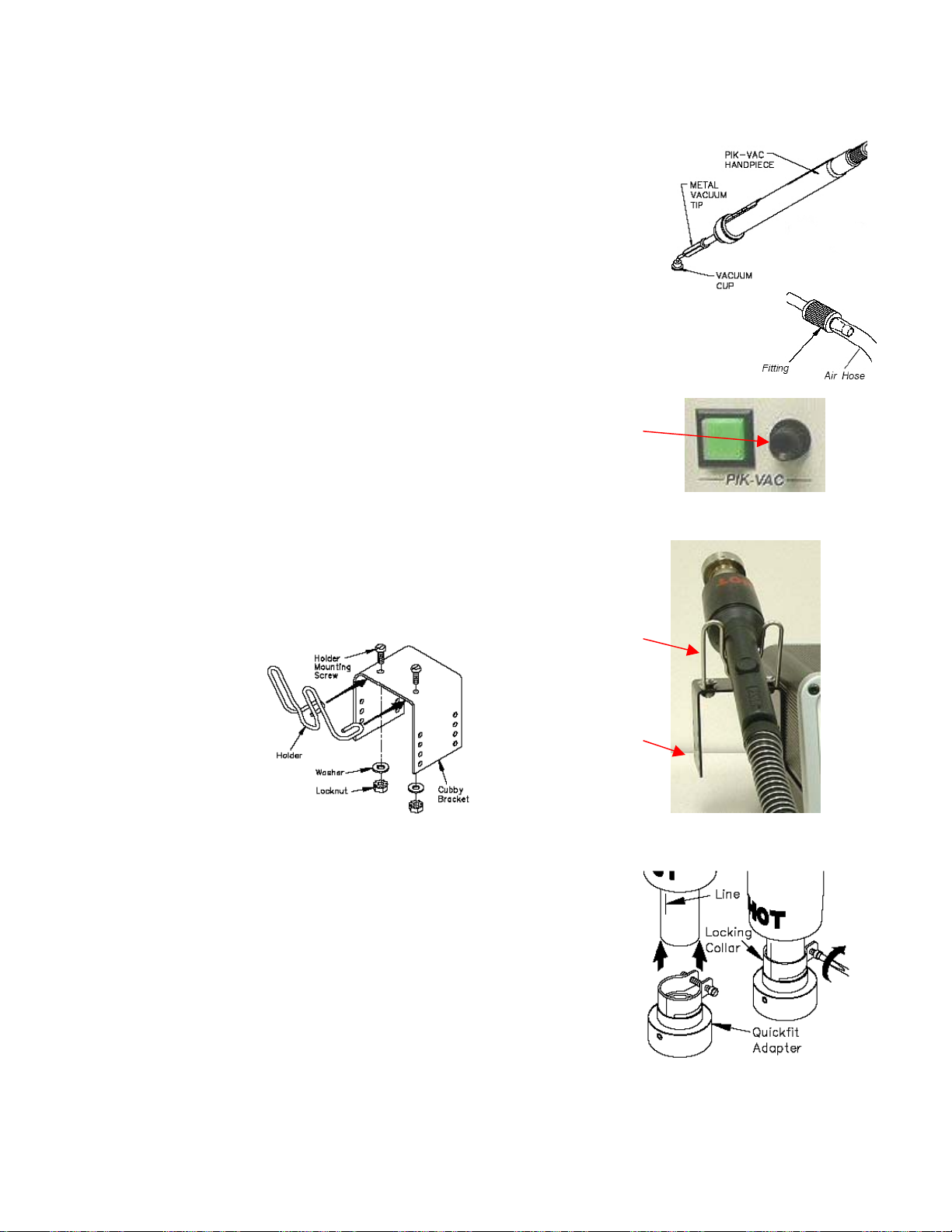
Vacuum Pick
Set-Up
1. Locate the Pik-Vac (P/N 7027-0001-P1) and the Vacuum Cup
Kit (P/N 6993-0154) supplied with the system.
2. Attach the ridged end of a male quick connect hose mount
Fitting to each end of the Air Hose.
3. Attach one male quick connect hose Fitting (with attached Air
Hose) to the rear of the Pik-Vac Handpiece.
4. Insert the other male quick connect hose
Fitting (with attached Air Hose) into the LoFlo Vacuum Port.
5. Attach the Metal Vacuum Tip, with the appropriate vacuum cup,
to the end of the Pik-Vac Handpiece.
Handpiece Stand
Using the supplied hardware, attach the Handpiece
Retainer and the Mounting Bracket as shown.
QuickFit Nozzle Adapter
The ST 325 QuickFit Adapter allows you to easily change out any
PACE ST 325 Nozzle. Attach the adapter to the handpiece heater
using the following instructions.
1. Insert the QuickFit Adapter into the end of the handpiece heater as
shown.
2. Position the QuickFit Adapter so the Line on the heater is aligned
with one of the 3 lines (1 long & 2 short lines) on the Locking
Collar. Tighten Collar Locking Screw to secure adapter in position.
Handpiece
Retainer
Mounting
Bracket
©2004 PACE Inc., Annapolis Junction, Maryland Page 9 of 32
All Rights Reserved
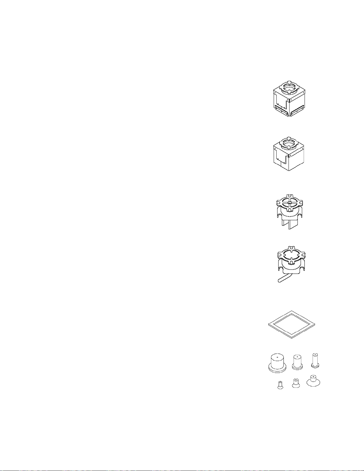
Nozzle Selection
Selection of the proper Nozzle is essential for achieving a quality component removal or installation. Each
ST 325 Nozzle is designed to properly direct the heated air. Custom nozzles are available upon request.
ST 325 Nozzles are available in 4 basic configurations.
Vented Air Nozzles (V-A-N)
Are used for removal/replacement of BGA components.
Box Nozzles
Used for removal/replacement of surface mount components having solder
connections on 4 sides of the component (e.g., QFPs & PLCCs).
Pattern Nozzles
Used for removal/replacement of surface mount components having solder
connections on 2 sides of the component (e.g., SOICs).
Single Jet Nozzles
Available in straight, curved and flat end versions, these nozzles are used for
removal/replacement of small surface mount components (e.g., chip components),
small QFPs, Land Grid Arrays (e.g., those used on pagers & cellular telephones) or
for reflowing solder on single solder connections.
Template Selection
Alignment Templates are used as an aid in aligning V-A-N Nozzles to the PCB Assembly when installing
Ball Grid Arrays (BGAs). The I.D. (Inside Dimension) of the template should
match the perimeter of the BGA land pattern.
Vacuum Cup Selection
Selection of the proper size vacuum cup is important for achieving an adequate
holding force for each component. The cup selected should be as large as
possible without exceeding the body size of the component. Vacuum cups are
consumable items which deteriorate over a period of time.
©2004 PACE Inc., Annapolis Junction, Maryland Page 10 of 32
All Rights Reserved
 Loading...