

Page 1
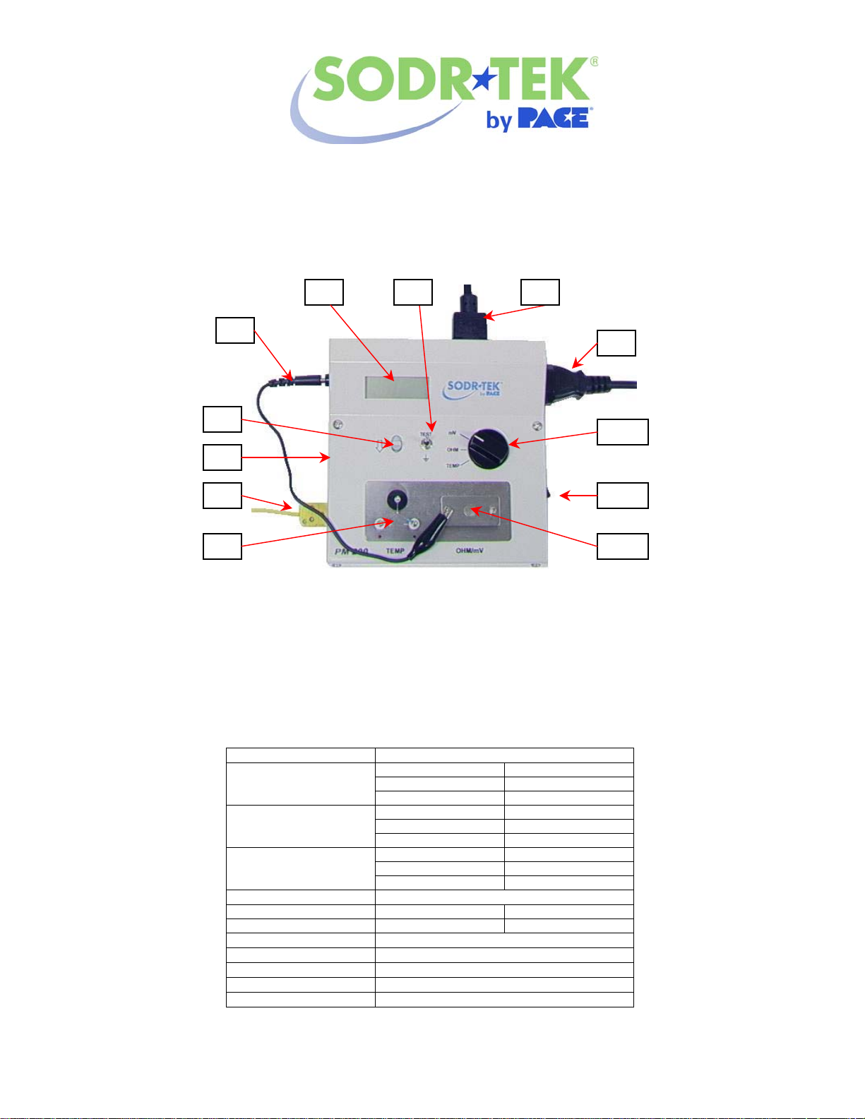
Parts Identification
1. Temperature Sensor.
2. External K-Type Thermocouple.
3. C / F Switch
4. Sensor Tension Control.
5. Grounding Cable with Clip.
6. LCD Display.
Specification
PACE PM 200 Process Monitor
PACE PART NUMBER 8007-0464-P1
Operation and Maintenance Instructions
MANUAL NUMBER 5050-0562
7. Test /Ground Switch.
8. Power Cord / Power Inlet.
9. Male to Female Power Cord / Power Outlet.
10. Function Control.
11. Power Switch.
12. Conduction Plate.
Item Temperature Tester
Measuring Range Temperature 0-600 °C / 32-1200 °F
Voltage 0-90mV (AC)
Resistance 0-90 Ω
Resolution Temperature 1 °C / 1 °F
Voltage 0.1mV
Resistance 0.1 Ω
Accuracy Temperature ± 3 °C ± 6 °F
Voltage ± (3%±2 digit)
Resistance ± (1%±2 digit)
Temperature Sensor K Type Thermocouple
Display Liquid Crystal Display 3.50Digits
Display of Over-range -1,1
Voltage Measurement Conform to MIL-STD-2000
Power Consumption 1W
Dimension 150mm (W) X 55mm (H) X 150mm (D)
Weight Approximately 910 grams (2 lb
Operational Environment 0-40 °C /32-104 °F 0-80RH%
©2005 PACE Incorporated, Annapolis Junction, MD All Rights Reserved. Printed in the USA
www.paceworldwide.com
Page 2

Maintenance
1. Periodically remove flux splatter from unit using an alcohol-moistened cloth.
2. Repeated measurement will cause sensor to wear out. A properly installed sensor is critical to
the accuracy of this device.
3. Handle the temperature sensor carefully. The temperature sensor is extremely thin and may
break if handled incorrectly.
4. Before measuring, coat the soldering tip with fresh solder. This is necessary to ensure proper
contact between the tip and temperature sensor or tip and conduction plate.
5. When performing test, never let the soldering tip touch the stainless steel housing below the
measuring point. An error in measurement will occur.
6. Insure the power source is properly ground before operating this device.
7. If tests are preformed using the PACE TD-100 handpiece, make sure the Tip Heater Cartridge is
seated firmly in handle.
8. When operating the PS-90 or SX80 handpiece, make sure inside surfaces of the heater
assembly and setscrew are clean and free of oxidation. Insure the setscrew is tight before
continuing with test.
Sensor Installation
1. To install a new sensor (P/N 1285-0046-P1), adjust the
tension control slide to the down position.
2. Slip sensor loops onto the three posts making sure to
match positive and negative end to corresponding post.
Tension control
Note
Open sensor error will be displayed as “1”. Check
sensor post connections. If necessary, replace sensor.
Sensor posts
Measuring Tip Temperature
1. Connect power cord to PM200.
2. Connect your PACE soldering station power supply with handpiece
and tip to the PM200 using the supplied male to female power
cable.
3. Turn both the PM200 and soldering station power switch to the ON
position.
4. Select Celsius or Fahrenheit using the °F / °C Conversion Switch
on left side of unit.
5. Turn the dial control switch to “TEMP” position.
6. Clean and re-tin the handpiece tip with fresh solder.
7. Hold tip of handpiece to temperature sensor and heat the solder until display stabilizes. Add solder to tip
until sensor is immersed in solder.
8. Record displayed temperature value.
©2005 PACE Incorporated, Annapolis Junction, MD All Rights Reserved. Printed in the USA
www.paceworldwide.com
Page 3

A
Measuring the Difference In Potential Between Tip and Ground
1. Connect power cord to PM200.
2. Connect your PACE soldering station power supply with handpiece to the PM200 using the supplied male
to female power cable.
3. Turn both the PM200 and soldering station power switch to the ON position.
4. Set power supply temperature to the highest setting possible. (900 ºF for Sodr-Tek units / 850 ºF for THC
models).
5. Turn the dial control switch to “mV” position.
6. Using the ground clip cable, connect the ground terminal (GRD) on the left side of the PM200 to the
conduction plate. DO NOT touch handpiece tip to the conduction plate during this step.
Holding the test / ground switch while recording displayed values will produce the
same internal grounding condition as the ground clip cable.
7. Record the value displayed on the LCD display as V 1.
8. Disconnect the ground clip from the conduction plate.
9. Clean and re-tin the handpiece tip with fresh solder.
10. Using the soldering handpiece, place a small bead of soldering
the center of the conduction plate and heat the solder until it has
become completely melted.
11. When the LCD display has stabilized, record the value as V 2.
12. Subtract V 1 from V 2 to derive the difference in potential
between the tip and ground.
Example: V 1 (00.1) – V 2 (00.9) = 0.8mV
Measuring the Resistance Between Tip and Ground
1. With PM200, soldering station, and handpiece connected, power on both units.
2. Set tip temperature to the highest setting possible. (900ºF for Sodr-Tek units / 850 ºF for THC models).
3. Turn the dial control switch to “OHM” position.
4. Using the ground clip cable, connect the ground terminal (GRD) on the side of the PM200 to the
conduction plate.
5. Record the value displayed on the LCD display as R1.
6. Disconnect the ground clip from the conduction plate.
7. Clean and re-tin the handpiece tip with fresh solder.
8. Using the soldering handpiece, place a small bead of soldering the center of the conduction plate and
heat the solder until it has become completely melted.
9. When the LCD display has stabilized, record the value as R2.
10. Subtract R1 from R2 to derive the resistance from tip to ground.
Example: R1 (00.1) - R2 (00.4) = 0.3Ω
Note
PACE Incorporated
9030 Junction Drive
nnapolis Junction,
MD 20701
Tel: (301) 490-9860
Fax: (301) 498-3252
PACE Europe Limited
13 Tanners Drive
Blakelands
Milton Keynes
Tel: (44) 1908-277666
Fax: (44) 1908-277777
©2005 PACE Incorporated, Annapolis Junction, MD All Rights Reserved. Printed in the USA
www.paceworldwide.com
 Loading...