

Page 1

10 Series CNC
AMP
Software Characterization
Manual
Code: 45006667V
Rev. 10
PUBLICATION ISSUED BY:
OSAI S.p.A.
Via Torino, 14 - 10010 Barone Canavese (TO) – Italy
e-mail: sales@osai.it
Web: www.osai.it
Copyright 2001-2002 by OSAI
All rights reserved
Edition: July 2001
IMPORTANT USER INFORMATION
This document has been prepared in order to be used by OSAI. It describes the latest release of the
product.
OSAI reserves the right to modify and improve the product described by this document at any time
and without prior notice.
Actual application of this product is up to the user. In no event will OSAI be responsible or liable for
indirect or consequential damages that may result from installation or use of the equipment described
in this text.
Page 2

abc
Page 3

10 Series CNC - AMP Software Characterization Manual
UPDATES FOR THE PRESENT RELEASE
General
This publication has been issued with the software release 6.1.
This page lists the modifications to the manual in this edition.
PAGE TYPE OF UPDATE
INDEX updated
CHAPTER 1
Pages 26, 27, 28 added: a new paragraph concerning the “Variable Servo Error”
CHAPTER 3
Page 28
Page 31
updated: the description for position errors with/without VFF
changed: axis homing type (admitted values from 0 to 4) in the parameter
configuration
UPDATING
CHAPTER 4
Pages 3, 8
Page 21
CHAPTER 5
Page 27
Page 31
APPENDIX A
Page 20 added: error messages and recovery actions for AM193 and AM194.
added: the field “Alternative Interp. Plane” in the process configuration
added: a usage note in the definition of the G code in the “Interp. Plane” field
updated: the description for position errors with/without VFF
updated: axis homing type (admitted values from 0 to 4) in the axis configuration
10 Series CNC - AMP Software Characterization Manual (10)
Page 4

abc
Page 5

Preface
10 Series CNC - AMP Software Characterization Manual
PREFACE
This manual describes the characterization phase of the 10 Series CNC system through use of the
AMP (Adjustable Machine Parameters) and Servo Monitor utilities. AMP allows the operator to enter
all the necessary parameters and information to configure the system and the various machining
processes. The Servo Monitor allows the operator to perform a tuning of the system in order to
achieve optimum performance.
The manual is intended for the operator that has in charge the system characterization after
installation.
REFERENCES
Read first:
• 10 Series CNC : Product Specification
For further information:
• 10 Series CNC : User Guide
• 10 Series CNC : Programmer Guide
10 Series CNC - AMP Software Characterization Manual (05) 1
Page 6

Preface
10 Series CNC - AMP Software Characterization Manual
SUMMARY
In this guide the operator will find a short description of all the configuration parameters as well as
the procedures for defining them.
1. General Concepts
Contains a description of the numerical control terms used within the manual.
2. AMP
Provides a general description of the AMP configuration procedures.
3. Global Parameters Configuration
Describes the data entries used for configuring the global parameters.
4. Process Configuration
Describes the data entries used for configuring the processes.
5. Axis Configuration
Describes the data entries used for configuring the axes.
6. Human Interface Configuration
Describes the data entries used for configuring the human interface.
7. The Servo Monitor
Describes the Servo Monitor Utility.
8. DSI Service Channel
Describes the DSI Service Channel Utility.
9. Emergency Diagnostic
Describes the Emergency Diagnostic Utility.
A. AMP - Error Messages
Contains the list of error messages completes this guide.
B. Generation of Help Files for OEM Softkeys
Contains instructions to generate help files for OEM defined softkeys.
C. Axis calibration from file
Contains instructions to introduce calibration points of an axis.
2 10 Series CNC - AMP Software Characterization Manual (05)
Page 7
Preface
10 Series CNC - AMP Software Characterization Manual
TERMINOLOGY
Some terms appearing throughout the manual are explained below.
Control Refers to the 10 Series CNC numerical control unit comprising front panel unit and
basic unit.
Front Panel Is the interface module between machine and operator; it has a monitor on which
messages are output and a keyboard to input the data. It is connected to the basic
unit.
Basic Unit Is the hardware-software unit handling all the machine functions. It is connected to
the front panel and to the machine tool.
Is connected to developments or circumstances which can make damages to
the system, to the equipments or to the operators.
Is connected to the information that it is necessary take in consideration in
order to avoid damages to the equipment in general.
Is connected to the operations that it is necessary to execute carefully in order
to assure the full success of the application.
10 Series CNC - AMP Software Characterization Manual (05) 3
Page 8

Preface
10 Series CNC - AMP Software Characterization Manual
END OF PREFACE
4 10 Series CNC - AMP Software Characterization Manual (05)
Page 9

10 Series - AMP CNC Software Characterization Manual
INDEX
GENERAL CONCEPTS
SYSTEM ARCHITECTURE................................................................................... 1-1
CLASSIFICATION OF THE MACHINE AXES .........................................................1-3
SERVO LOOP..................................................................................................... 1-4
Position tolerance....................................................................................... 1-5
Dead zone................................................................................................. 1-6
Travel limits................................................................................................ 1-6
Homing cycle .............................................................................................1-7
Manual/automatic switch search.................................................................. 1-9
Miscellaneous axis parameters ....................................................................1-10
Operating limits ..........................................................................................1-12
Measuring cycle .........................................................................................1-12
Coordinate display modes ........................................................................... 1-12
SPLIT AXES....................................................................................................... 1-13
DUAL AXES ........................................................................................................1-15
AXES WITH ROLLOVER..................................................................................... 1-16
DIAMETER AXES................................................................................................ 1-17
AUXILIARY AXES ............................................................................................... 1-18
SPINDLE AXIS ................................................................................................... 1-19
Spindle axis with gears ............................................................................... 1-19
Spindle axis ramp....................................................................................... 1-20
Spindle with trasducer................................................................................. 1-21
Spindle orientation ......................................................................................1-21
Shared Spindle........................................................................................... 1-22
HANDWHEEL...................................................................................................... 1-23
PART PROGRAM-LOGIC INTERFACE ................................................................. 1-24
Synchronous mode..................................................................................... 1-24
Asynchronous mode ...................................................................................1-24
Language expansion ...................................................................................1-24
PSEUDO AXES................................................................................................... 1-25
VIRTUAL AXES .................................................................................................. 1-25
USER INTERFACE .............................................................................................. 1-25
Logic display ..............................................................................................1-25
OEM softkey ..............................................................................................1-25
VARIABLE SERVO ERROR ................................................................................. 1-26
Index
10 Series CNC - AMP Software Characterization Manual (10) i
Page 10

Index
10 Series CNC - AMP Software Characterization Manual
AMP
SOFTKEY........................................................................................................... 2-1
AMP main menu ........................................................................................ 2-2
Help.......................................................................................................... 2-3
Activate..................................................................................................... 2-4
Select ....................................................................................................... 2-4
Characterization menu softkeys ...................................................................2-5
Operativity notes ........................................................................................ 2-7
Data Entry Storage .....................................................................................2-7
ENTER/EXIT THE CHARACTERIZATION............................................................... 2-8
Edit Comment............................................................................................ 2-10
Backup...................................................................................................... 2-10
Delete....................................................................................................... 2-11
Print.......................................................................................................... 2-11
AMP print utility error messages.................................................................. 2-18
GLOBAL PARAMETERS CONFIGURATION
HARDWARE (10/310, 10/110 AND 10/510 SYSTEM)............................................. 3-2
HARDWARE (10/565 and 10/585 SYSTEMS)........................................................ 3-5
GENERAL INFORMATION................................................................................... 3-8
LOGIC CONFIGURATION ....................................................................................3-10
Boolean Variables ...................................................................................... 3-10
Boolean Var (Variabili boolean).................................................................... 3-10
Short Variables .......................................................................................... 3-12
Double Variables ........................................................................................ 3-14
Auxiliary Axis General Information................................................................ 3-16
Select Auxiliary.......................................................................................... 3-18
Auxiliary Axis Characterization.................................................................. 3-19
Notes on characterization of digital drivers .................................................... 3-31
Physical Conn............................................................................................ 3-32
Axis Calibr .................................................................................................3-34
OPTIONS ........................................................................................................... 3-36
DOS Real-time ...........................................................................................3-37
END User Dos ........................................................................................... 3-38
DOS Graphics............................................................................................ 3-39
PROCESS CONFIGURATION
SELECT PROCESS .............................................................................................4-2
PROCESS CONFIG............................................................................................. 4-3
Proc Char.................................................................................................. 4-3
Proc Variables ........................................................................................... 4-9
Progr Char................................................................................................. 4-13
M Codes ....................................................................................................4-16
G Codes.................................................................................................... 4-20
GTL (Geometrical Technological Language) ................................................. 4-23
Virtual Axes............................................................................................... 4-25
E Parameters .............................................................................................4-27
User Variables ........................................................................................... 4-28
ii 10 Series CNC - AMP Software Characterization Manual (10)
Page 11

10 Series CNC - AMP Software Characterization Manual
AXIS CONFIGURATION
AXIS CONFIGURATION ...................................................................................... 5-1
Axis General Information............................................................................. 5-2
Pseudo Axes ............................................................................................. 5-5
Spindle...................................................................................................... 5-6
Notes on the characterization of digital drivers............................................... 5-14
Probing...................................................................................................... 5-15
Select Axis ................................................................................................5-17
Axis Characterization.................................................................................. 5-18
Notes on the characterization of digital drivers............................................... 5-32
Axis Charact (Slave axis selected with "Select Axis")................................... 5-33
Axis Calibration ..........................................................................................5-34
Physical Connection ...................................................................................5-37
HUMAN INTERFACE CONFIGURATION
HUMAN INTERFACE ........................................................................................... 6-1
H.I. Gen Info............................................................................................... 6-2
Add Scr Config ...........................................................................................6-5
Process Screen ......................................................................................... 6-7
Select Menu .............................................................................................. 6-8
OEM SK Config.......................................................................................... 6-10
Select DE.................................................................................................. 6-13
DE Config.................................................................................................. 6-15
PPDIR Config .............................................................................................6-18
Index
THE SERVO MONITOR
USING THE SERVO MONITOR............................................................................ 7-2
ENABLING THE SERVO MONITOR ......................................................................7-3
CHANGE PARAM................................................................................................ 7-4
DEFAULT VALUES.................................................................................... 7-4
ALTERING A VALUE.................................................................................. 7-4
Null Offset ..................................................................................................7-5
Tolerance................................................................................................... 7-6
Dead Zone................................................................................................. 7-8
Backlash ...................................................................................................7-9
KC KV VFF ............................................................................................... 7-10
Servo Error................................................................................................. 7-12
Feed/Acc/Jrk ............................................................................................. 7-13
Spindle...................................................................................................... 7-15
Operative Limits ......................................................................................... 7-18
Split Param................................................................................................ 7-19
Broken wire................................................................................................ 7-21
CONFIGURING THE OSCILLOSCOPE................................................................. 7-22
Config. oscill.............................................................................................. 7-22
Feedrate on the profile ................................................................................ 7-24
Feed calculated (single axis) .......................................................................7-26
Following error (single axis) .........................................................................7-28
Feed and error on same axis....................................................................... 7-30
10 Series CNC - AMP Software Characterization Manual (10) iii
Page 12

Index
10 Series CNC - AMP Software Characterization Manual
CONTINUOUS MODE.......................................................................................... 7-31
TRIGGER MODE................................................................................................. 7-31
DATA DISPLAY MODES ......................................................................................7-31
ANALYZING THE DATA (EXAME)......................................................................... 7-34
Main menu and graphics............................................................................. 7-34
Zoom......................................................................................................... 7-35
Time Enlarge.............................................................................................. 7-35
Dimension ................................................................................................. 7-35
Check ....................................................................................................... 7-36
Save ASCII ................................................................................................ 7-36
SAVING AND RESTORING DATA........................................................................ 7-37
Save.......................................................................................................... 7-37
Restore ..................................................................................................... 7-38
ERROR MESSAGES ............................................................................................7-39
DSI SERVICE CHANNEL
SETUP ............................................................................................................... 8-2
DESCRIPTION.................................................................................................... 8-3
SAVE ALL.......................................................................................................... 8-4
Format and syntax of the configuration file.................................................... 8-5
LOAD................................................................................................................. 8-8
SELECT AXIS .....................................................................................................8-12
READ BLOCK..................................................................................................... 8-14
WRITE DATA ......................................................................................................8-16
COMMAND......................................................................................................... 8-17
SAVE AX INFO................................................................................................... 8-18
show load log ....................................................................................................8-19
LOADING DSI DRIVErs PARAMETERS ................................................................ 8-20
Usage Mode .............................................................................................. 8-20
Application notes ........................................................................................8-21
Error messages.................................................................................................. 8-22
EMERGENCY DIAGNOSTIC
EmergenCY START ............................................................................................9-1
EMERGENCY DIAGNOSTIC Screen Softkeys.............................................. 9-2
TABLE RESET UTILITY....................................................................................... 9-4
Reset Request........................................................................................... 9-5
Select Tables............................................................................................. 9-6
Delete Tables............................................................................................. 9-7
LANGUAGE MANAGEMENT UTILITY................................................................... 9-10
Activate..................................................................................................... 9-13
Create....................................................................................................... 9-15
Delete....................................................................................................... 9-17
Text Handler .............................................................................................. 9-18
Text Types .................................................................................................9-19
Compare.................................................................................................... 9-21
Update...................................................................................................... 9-23
Show diff.................................................................................................... 9-24
Modify ....................................................................................................... 9-25
EDITOR FOR MODIFYING TEXT FILES ................................................................9-26
iv 10 Series CNC - AMP Software Characterization Manual (10)
Page 13

10 Series CNC - AMP Software Characterization Manual
SoftkeyS of the editor FOR CONFIGURATION File MODIFICATION .................... 9-29
DELETE .................................................................................................... 9-29
INSERT..................................................................................................... 9-29
MODIFY.................................................................................................... 9-30
SK MODIFY............................................................................................... 9-31
DE MODIFY............................................................................................... 9-33
HELP MODIFY........................................................................................... 9-34
ERR MODIFY ............................................................................................ 9-36
ERROR ATTRIB ......................................................................................... 9-37
VIEW........................................................................................................ 9-38
BACKUP ................................................................................................... 9-39
RESTORE ................................................................................................. 9-40
EXIT.......................................................................................................... 9-41
OFF-LINE version of language utility................................................................. 9-42
GENERAL EXEC FILE COMPILING UTILITY......................................................... 9-44
DSI REBOOT CONFIGURATION.......................................................................... 9-47
CFG DSI Setup.......................................................................................... 9-48
DATA RESTORE................................................................................................. 9-49
error MESSAGES ............................................................................................... 9-50
Reset Tables Utility .................................................................................... 9-50
Utility Languages ........................................................................................9-52
Utility Compiler........................................................................................... 9-58
Utility DSI Reboot Configuration................................................................... 9-60
Index
AMP - ERROR MESSAGES
Message Description And Recovery Action........................................................ A-1
GENERATION OF HELP FILES FOR OEM SOFTKEYS
HELP file - menu association....................................................................... B-1
AXIS CALIBRATION FROM FILE
General ............................................................................................................. C-1
File Format ................................................................................................ C-2
Error conditions and messages ....................................................................C-3
10 Series CNC - AMP Software Characterization Manual (10) v
Page 14

Index
10 Series CNC - AMP Software Characterization Manual
END OF INDEX
vi 10 Series CNC - AMP Software Characterization Manual (10)
Page 15

Chapter
1
GENERAL CONCEPTS
This chapter provides a glossary of the terms used in the present AMP Configuration Guide. For
users who are not familiar with NC technology it may serve as an introduction to the philosophy
underlying system operation. Users with extensive NC experience can use it as a source of lexical
reference. Special attention has been devoted to the classification of the axes and to the description
of the characteristics of the various types.
Users already familiar with numeric control machines may use this chapter as a terminology
reference.
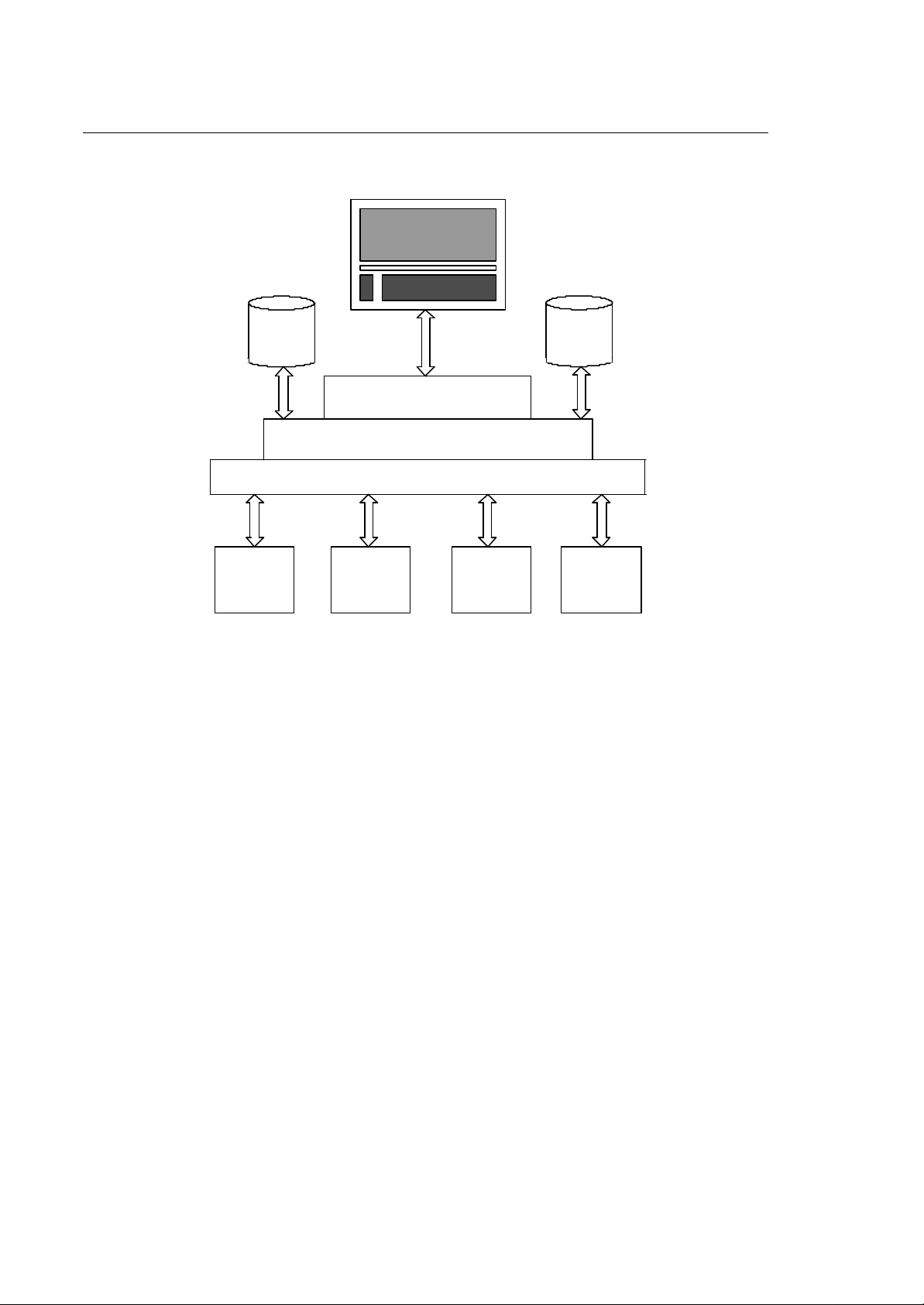
SYSTEM ARCHITECTURE
The architecture of 10 Series CNC can be broken down into four partitions, each of which controls a
specific set of features.
10 Series CNC - AMP Software Characterization Manual (10) 1-1
Page 16
Chapter 1
General Concepts
HARD
DISK
UNIT
UTILITIES
OPERATOR PA NEL
COMMUNICATIONS
OPERATING SY STEM
INTER-PROCESS COMMUNICATIONS
CN
PROCESS
I/O
INTERFACE
FLOPPY
DISK
UNIT
H
HUMAN
INTERFACE
The major function of each partition is as follows:
Numerical Control Includes the part program interpreter, the axes interpolator and the process
manager for machining centers.
Utilities I ncludes a series of text-only and graphics packages that can be used by
the end user, the OEM or the technical assistance.
I/O Interface Controls the execution of the machine tool/control interface code that has
been developed by the OEM.
Human Interface Controls all the data input and display operations and the man/machine
interface.
1-2 10 Series CNC - AMP Software Characterization Manual (10)
Page 17

Chapter 1
General Concepts
CLASSIFICATION OF THE MACHINE AXES
10 Series CNC can control the following types of axes:
Coordinated axes These are physical axes that move in coordination with each other.
Each 10 Series CNC AMP process can move 6 simultaneous axes
and up to 9 coordinated axes.
Auxiliary axes
Spindle axis
The axes can also be classified according to the type of move that they must carry out:
linear axis
rotary axis
split axis
dual axis
diameter axis
These are physical axes that are not requested to move in coordination
with each other.
This is the tool-holder spindle. 10 Series CNC can associate one
spindle with each process.
It is an axis moving on a rectilinear trajectory
It is a coordinated axis programmable in degrees.
It is a physical axis coupled to a pair of motors for synchronized
motion.
It is an axis whose moves are dependent on the moves of the master
axis to which it is coupled.
It is a coordinated axis that must be programmed and displayed with a
2 coefficient.
10 Series CNC - AMP Software Characterization Manual (10) 1-3
Page 18

Chapter 1
General Concepts
SERVO LOOP
10 Series CNC permits to define the algorithms that are used for servo loop control of each axis.
Such algorithms are based on three configurable constants, Kc, Kv and Kcs. 10 Series CNC uses
these constants in the following formula:
V
= (Le * Kv + Vff) * Kc
out
Where:
Vout
Le
Kv
Vff
The units of measure for the constants are: Le [mm], Kv [1/s], Vff [mm/s] (Le * Kv + Vff) represents a
velocity. Therefore, Kc is a velocity-to-voltage conversion factor .
The control applies the following internal formula:
Where:
Le'
Vff
output voltage
lagging error
servo loop gain
velocity feed forward
V
out
is the lagging error expressed in "encoder pulses"
is a function of the interpolation clock
is the voltage output by the Digital/Analog converter
is the variance between the programmed axis
position requested by the control and the actual
position measured by the position transducer
is the position loop gain
is a velocity value that is proportional to the
programmed axis feedrate.
= Le' * K + Vff * Kc
K
K and Kc are calculated using parameters established in the system configuration. The formulas are:
1-4 10 Series CNC - AMP Software Characterization Manual (10)
is the result of multiplying Kc by Kv
Kc =
K =
Vm*60
Fm
Vm*60
Fm
*
*
Pm
Pe
60000
Cki
*
8192
*
10
8192
* (Kv * 16.66666666...)
10
Page 19
For the spindle, the formula is:
Vm
Fm
*
8192
10
Kcs =
Where:
Vm = maximum voltage
Fm = maximum velocity
Pm = mechanical pitch
Pe = electrical pitch
Cki = interpolator clock [ms]
8192 is the number of possible output levels for the D/A converter
10 is the maximum positive or negative voltage output of the D/A converter
60000 is the minute-to-millisecond conversion factor.
Chapter 1
General Concepts
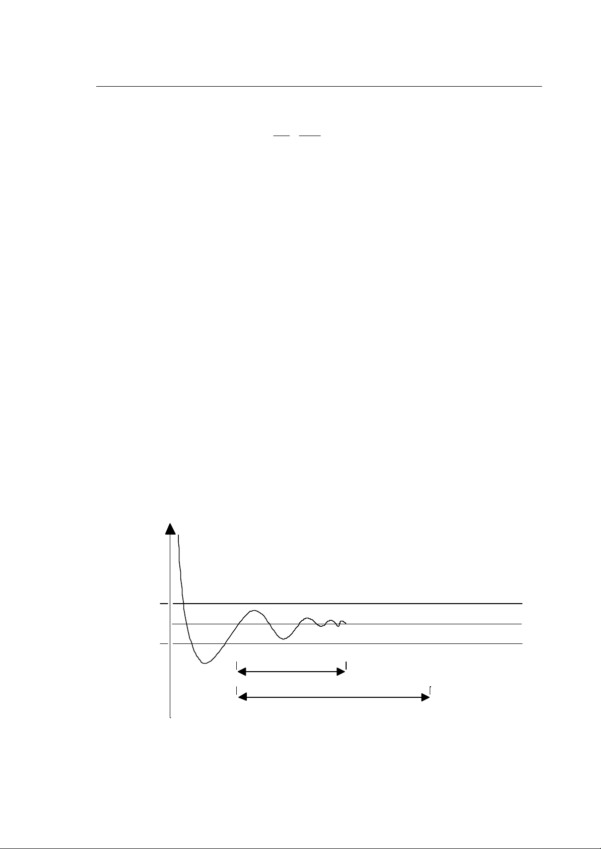
Position tolerance
The position tolerance is the threshold within which the axis must position at motion end. If the axis
is out of tolerance, the move is not considered terminated.
When a move ends, if the position control is active, the system checks that all the axes are in the
programmed position and that their lagging error (Le) is smaller than the threshold configured in the
"in position band" field.
To enhance the positioning accuracy, the "in position band" threshold must remain active during an
interval specified in the "in position window" field. If it does not, or if the positioning error is out of
tolerance after the interval specified in the "in position time-out", the system generates an emergency
condition.
lagging
error
in position
band
t
in position window
in position time-out
10 Series CNC - AMP Software Characterization Manual (10) 1-5
Page 20
Chapter 1
General Concepts
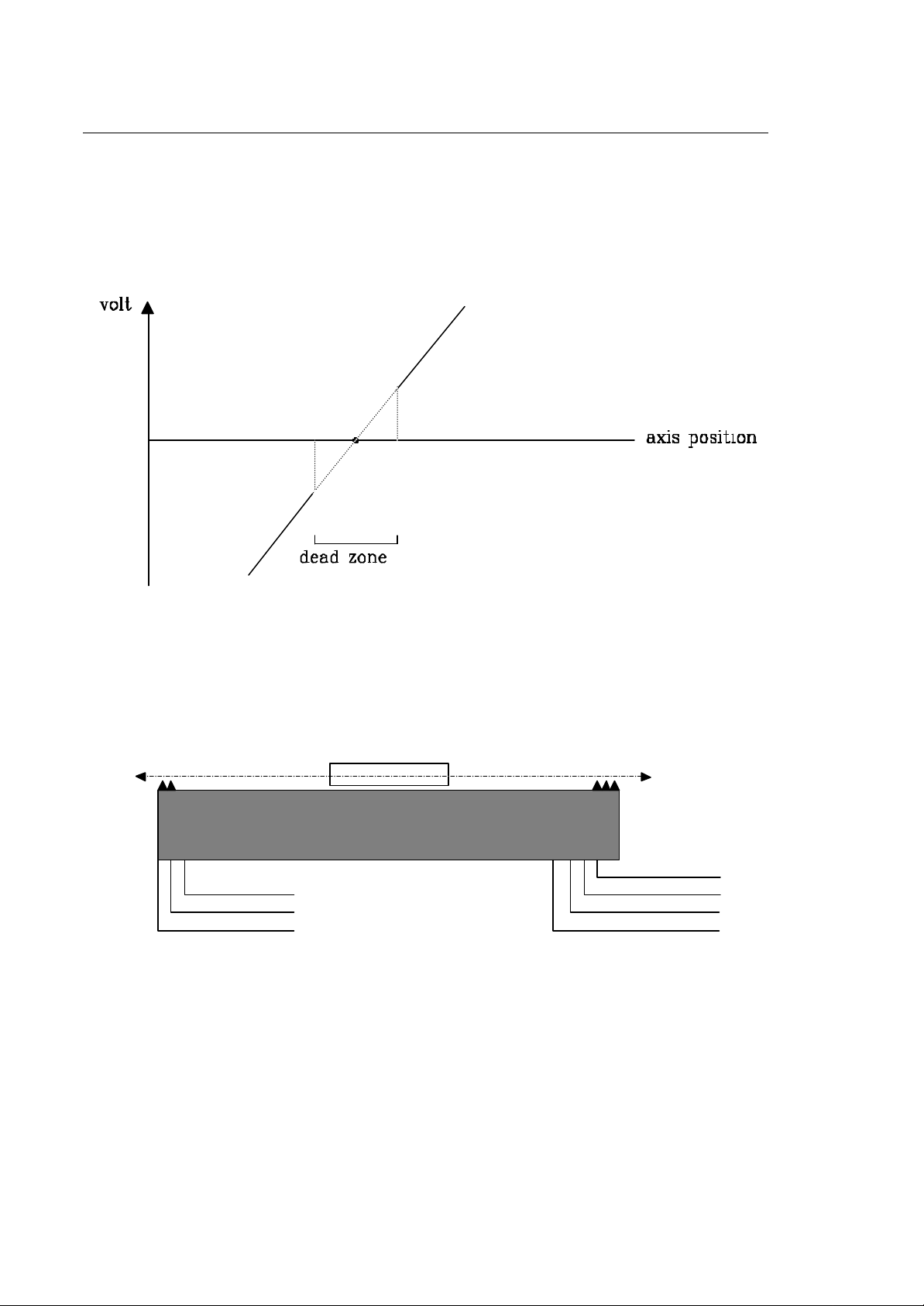
Dead zone
It is the threshold within which the D/A reference voltage output remains to zero irrespective of the
position error.
The dead zone must be smaller than the position tolerance.
Travel limits
Each axis moves within the limits of an operating field, which is a function of the characteristics of the
machine and can be established by means of physical and/or calculation devices which protect the
axis from erroneous operation or loss of control.
+
ov er trave l+
opera tin g lim itend o f tra v e l -
overtrav el -
The axis travel limits may be controlled by:
• positive/negative end of travel microswitches
• positive/negative end of travel microswitches
• positive/negative operating limits
end of travel+
opera ting lim it+
zero microswitch
NOTE:
In many applications zero microswitch can be coincident with end of travel.
1-6 10 Series CNC - AMP Software Characterization Manual (10)
Page 21
Chapter 1
General Concepts
The microswitches start operating as soon as the machine is switched on whereas the operating
limits, which are based on the axes positions, start operating only after the axes have been homed.
The overtravel microswitches are normally connected directly to the power circuitry of the axes.
In order to enable the travel microswitches that are connected to the I/O board they must be managed
by the logic.
Operating limits are managed directly by the control. While the control executes a special cycle,
such as tool or pallet change, the operating limits can be disabled or modified by the logic to allow
displacements beyond the limits. Operating limits must be disabled/modified with standstill axes.
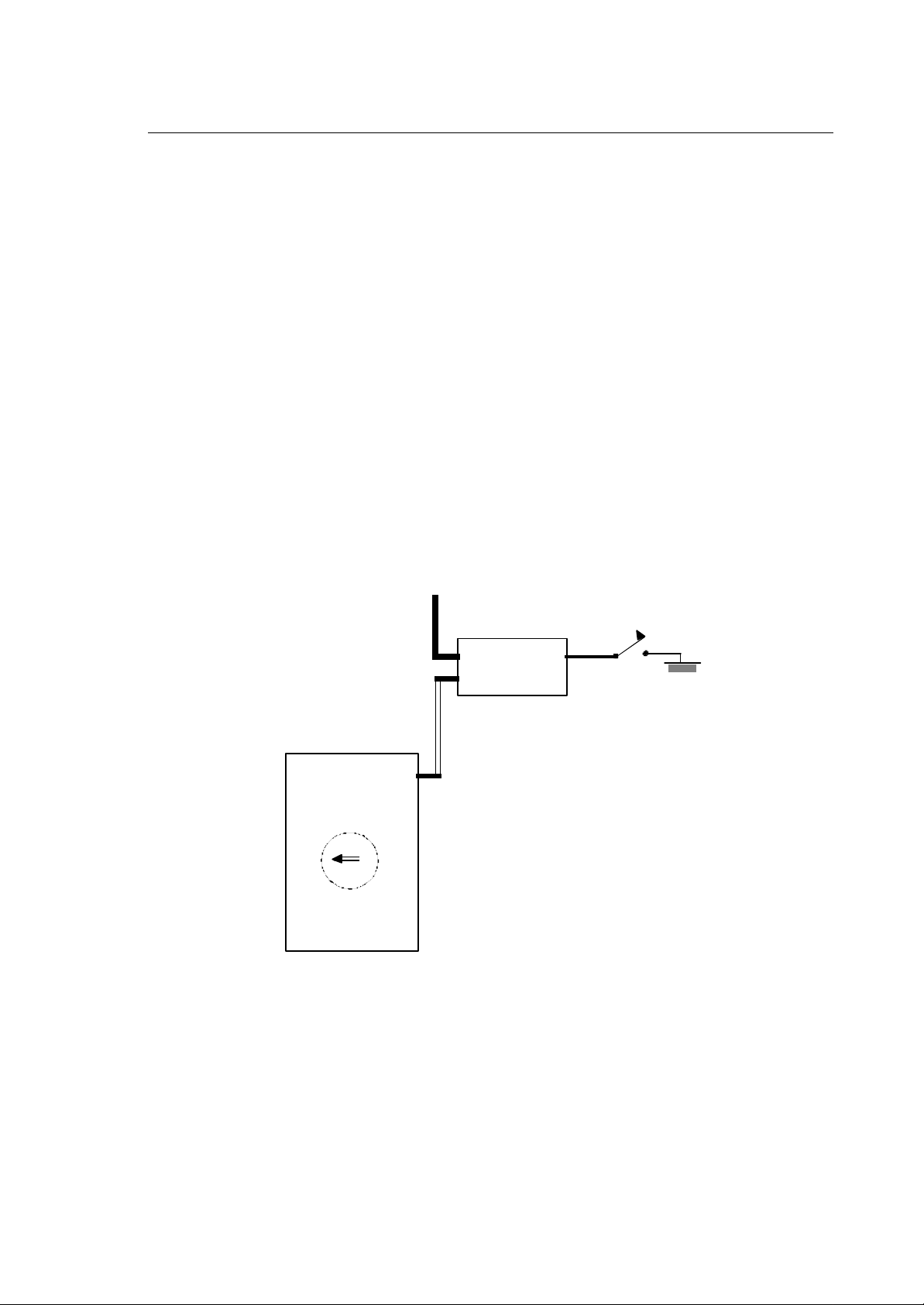
Homing cycle
Each time the system is switched on it is necessary to execute a homing cycle, i.e. to move the
axes to the microswitch that is considered as the machine zero. The aim of this operation is to reset
the internal counters that measure the axes positions. Axes home microswitch inputs are managed
by the foreground logic, whose status can be read in status words SW03 and SW04 (refer to the
"PLUS Application Manual").
This cycle is defined as home cycle.
I/O C AR D
FOREGROUND
SW
I/O RIN G
MODU LE
optical fiber
Ixx
The status of signals SW3 and SW4 must be interpreted as follows:
1= microswitch released
0= microswitch closed
10 Series CNC - AMP Software Characterization Manual (10) 1-7
Page 22

Chapter 1
General Concepts
To invert this operation mode it is necessary to write the NOT operator in the logic equations.
The homing cycle makes all the requests and signal controls that permit to refer the machine zero to
the initial time.
A homing cycle can be broken down into four main steps:
1. Zero switch search
During this step the axis makes a linear displacement in search of the zero microswitch. As the
contact with the microswitch occurs, the axis decelerates until it comes to a complete stop.
2. Zero switch release
n this step the axis reverts the direction of motion and moves until the zero microswitch is released.
The return velocity is equal to the configured "home position feed" and cannot be altered by the "feed
override".
3. Electric zero search
This step starts when the microswitch is released. The system waits for the electrical zero (i.e.
marker ) to be read and then stops the axis.
4. Return to electric zero
After the system has acquired the coordinates in which the electrical zero was read, the axis is
returned to the zero position.
If at cycle start the microswitch is already closed, the system will carry out only the last three steps.
If the axis is configured with an optical linear scale, the microswitch is assumed to be missing and
1only the last two steps will be carried out: in this case the electrical zero switch search speed will
be the one used in manual mode.
The homing cycle will be interrupted if the system is reset or put on hold. To resume the cycle a
CYCLE START command must be given.
1-8 10 Series CNC - AMP Software Characterization Manual (10)
Page 23
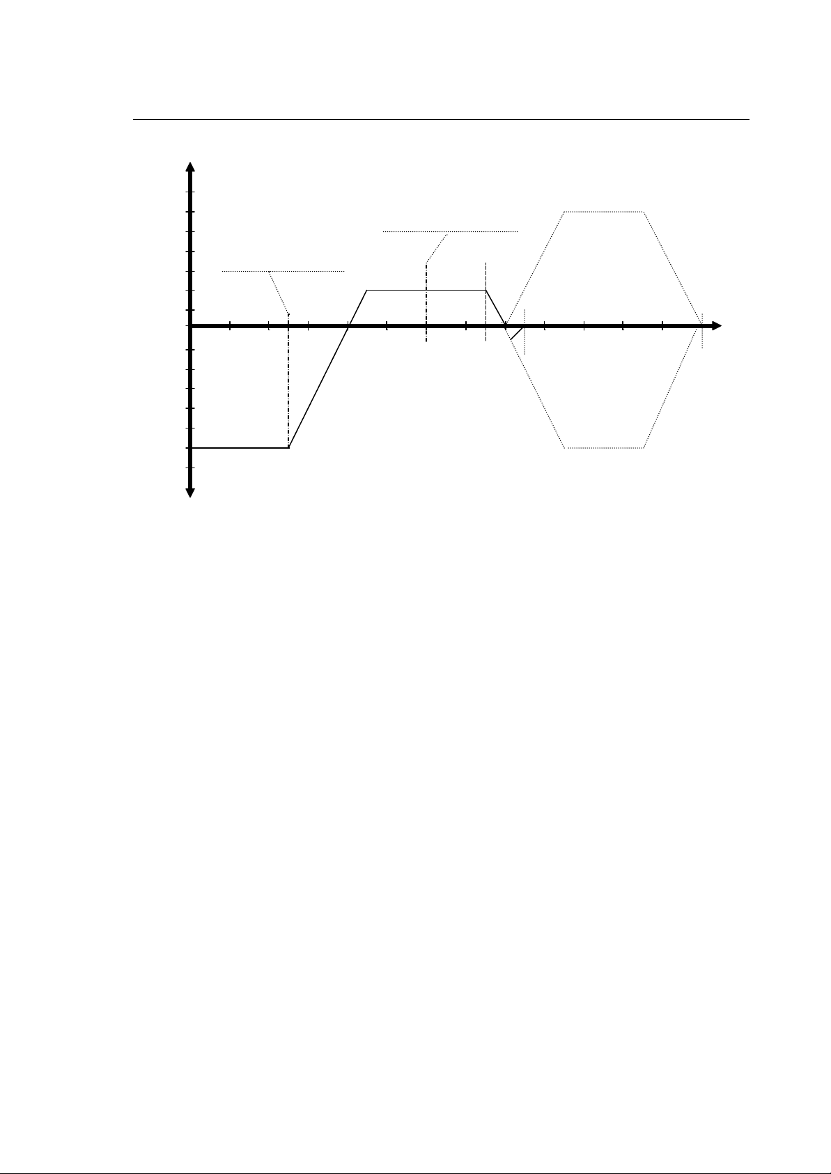
F +
" h o m e l i m it s w it c h
r e l e a s e d " d e t e c t e d b y
P .L . U . S . a n d
" h o m e li m i t s w it c h
p r e s s e d " d e t e c t e d b y
P . L .U . S . a n d
n o t i f i e d t o t h e s y s t e m
O
" m a nua l fe ed " - "m anu al" feed
n o ti f i e d t o t h e s y s t e m
m a rk er
"h om e fe ed"
AX IS H O M E D
w /o nu ll offs e t
+ "m anu al" f eed
Chapter 1
General Concepts
t
A X IS H O M E D
w ith nu ll offs e t
F -
Manual/automatic switch search
The switch search can be carried out manually or automatically. The "homing cycle type" field
permits to define the switch search mode to be used in the homing cycle for each process.
Manual switch search
The characteristics of the manual switch search cycle to be carried out by the process axes are as
follows:
1. prior to starting the cycle the operator must check that the selected direction of motion is
compatible with the configured direction.
2. during the first step, i.e. while the axes are moving towards the microswitch, the operator must not
release the CYCLE START pushbutton. If the command is to be sent by the logic, this means that
no CYCLE STOP command must be given.
3. after the microswitch has been found the homing cycle will be completed even if the CYCLE
START pushbutton is released and unless a RESET or HOLD command is given.
Automatic switch search
The characteristics of the automatic switch search cycle are:
1. the direction of motion is automatically selected by the control.
2. after the homing cycle has been launched, the operator can release the CYCLE START
pushbutton. The cycle will be completed unless a RESET or HOLD command is given.
10 Series CNC - AMP Software Characterization Manual (10) 1-9
Page 24

Chapter 1
n
General Concepts
Miscellaneous axis parameters
10 Series CNC also allows characterization of the following axis parameters:
1. null offset
2. home position
corrects the position of the zero microswitch
defines a machine zero that is independent from both the physical
position of the zero microswitch and the actual axes displacement.
c (machine zero)
b (theoretical ho me switch )
a (physical home switch)
The positions shown in the figure are as follows:
a) physical position of the zero microswitch
b) theoretical position of the zero microswitch
home
positio
null
offset
c) machine zero referred to the theoretical machine zero with respect to which all the other axis
position parameters are defined.
The examples that follow show how to use these parameters:
correct microswitch position
machine zero on the zero microswitch
a=b=c
absolute
position
transducer
plane
physical ho me switch
0
0
theoretical
machine zero
null offset = 0
home position = 0
100
100
1-10 10 Series CNC - AMP Software Characterization Manual (10)
Page 25
Chapter 1
General Concepts
microswitch position error
machine zero on the microswitch
absolute
position
transducer
plane
a=c
-5
0
null offset
physical home switch theoretical
b
0
machin e zero
no microswitch position error
offset between machine zero and physical microswitch
a=b
absolute
position
transducer
-100
0
null offset = +5
home position = 0
100
+1055
null offset = 0
home position = +100
c
0
100
plane
home position
physical home switch
theoretical
microswitch position error
offset between the machine zero and the zero microswitch
b
theoretical
absolute
position
transducer
plane
a c
-105 -100
null offset
physical ho me switch
machine ze ro
null offset = +5
home position = +100
0
+10550
home position
machine zero
10 Series CNC - AMP Software Characterization Manual (10) 1-11
Page 26

Chapter 1
General Concepts
Operating limits
The operating limits are defined with respect to the machine zero (c) in the AMP.
Measuring cycle
The coordinates read by the axes boards are referred to the machine zero (c).
Coordinate display modes
10 Series CNC permits the display of the following axis coordinates:
Absolute coordinates
Machine coordinates
Work coordinates
Distance to go
Error
The example that follows illustrates an axes calibration sequence.
1. Set the "null offset" and "home position" fields in the AMP to zero.
2. Key in the corrections to the geometrical errors in the AMP. This corrections are based on the
mecahnical distances to the physical microswitch.
3. Switch off and reboot the control.
4. Home the axis.
5. Move the axis to the position in which the zero microswitch should have been wired.
6. With the axis in this position read the "absolute position" coordinate.
7. Write this value in the "null offset" AMP field for the axis in object.
referred to the machine zero (c)
referred to the machine zero (c) and including the origins
programmed coordinates
difference between programmed and machine coordinates
difference between interpolated and real coordinates
8. If the home position is to be established on a value other than zero, write this value in the "home
position" AMP field for the axis in object.
9. Switch off and reboot the control.
10. From this point, all the machine coordinates are measured with respect to the "machine zero".
11. If necessary, define the operating limits in the AMP. These limits are always referred to the
"machine zero".
1-12 10 Series CNC - AMP Software Characterization Manual (10)
Page 27
Chapter 1
General Concepts
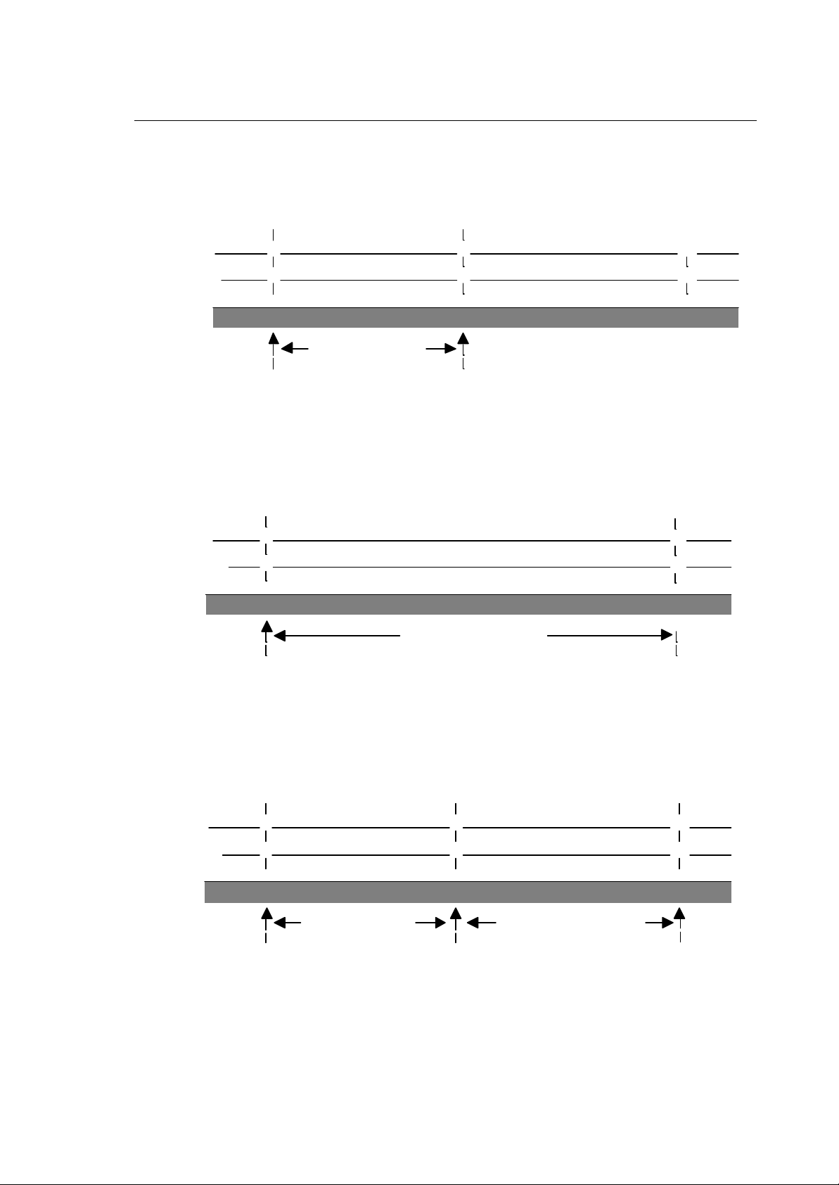
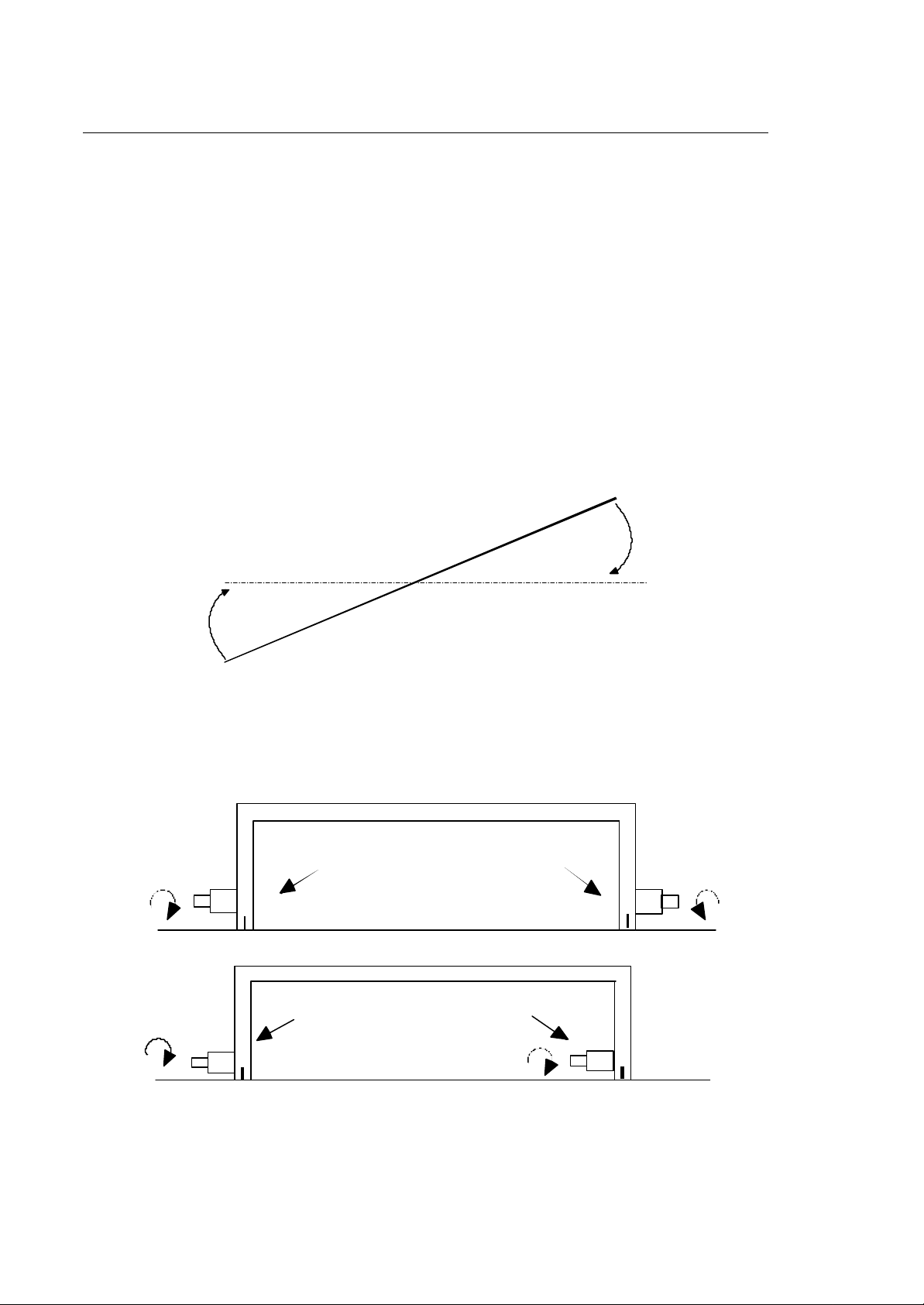
SPLIT AXES
A split axis (gantry) is a physical axis coupled to a pair of motors or drives. Split axes are typical of
large machines and of machines with special mechanical requirements, such as
From the User's standpoint, a split axis is seen as one single axis configured as a Master.
Servo motor 1
Axis
Servo motor 2
The parameters that configure a split axis are:
SKEW It is the maximum acceptable disalignment between two physical axes. Two
maximum values are configured: the first one (Max Skew Error) is used both
during movement for non referred axes and during the marker search; the second
(Skew Error) is used for all other movements for referred axes and after the marker
search.
When the current skew error exceeds the configured value, an emergency
condition (Skew Error) occurs.
SKEW GAIN permits to specify the skew compensation value.
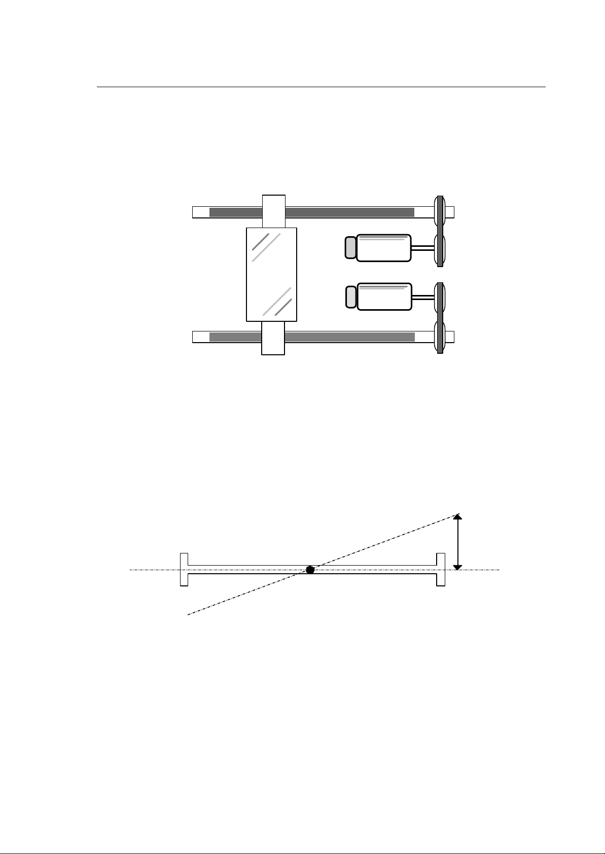
SKEW
When the split axis is enabled, the system calculates at each sampling the lagging errors of the
master (Lem = Lagging Error Master) and the slave (Les = Lagging Error Slave).
The misalignement (SKEW) can be calculated as follows:
SKEW = Lem - Les
10 Series CNC - AMP Software Characterization Manual (10) 1-13
Page 28
Chapter 1
General Concepts
The result of multiplying the SKEW value by the SKEW GAIN can be used for calculating new lagging
errors with the folllowing formulas:
Lem' = Lem + (Skew Gain * (Skew/2 ) )
Les' = Les - (Skew Gain * (Skew/2) )
If these new lagging errors are multiplied by a K constant, the resulting voltages on the D/A converter
represent positive and negative skew compensations to be applied to the master and the slave.
Such compensation tends to re-align the axes correctly.
In case of emergencies (servo, error, skew error ...) and of all operations generating disabling and
abling of a couple of split axes, it is necessary to refer the axes again in order to ensure correct
application of configured null offset and home position parameters and recuperate the misalignment
between the two physical axes that the activation/deactivation condition may have generated.
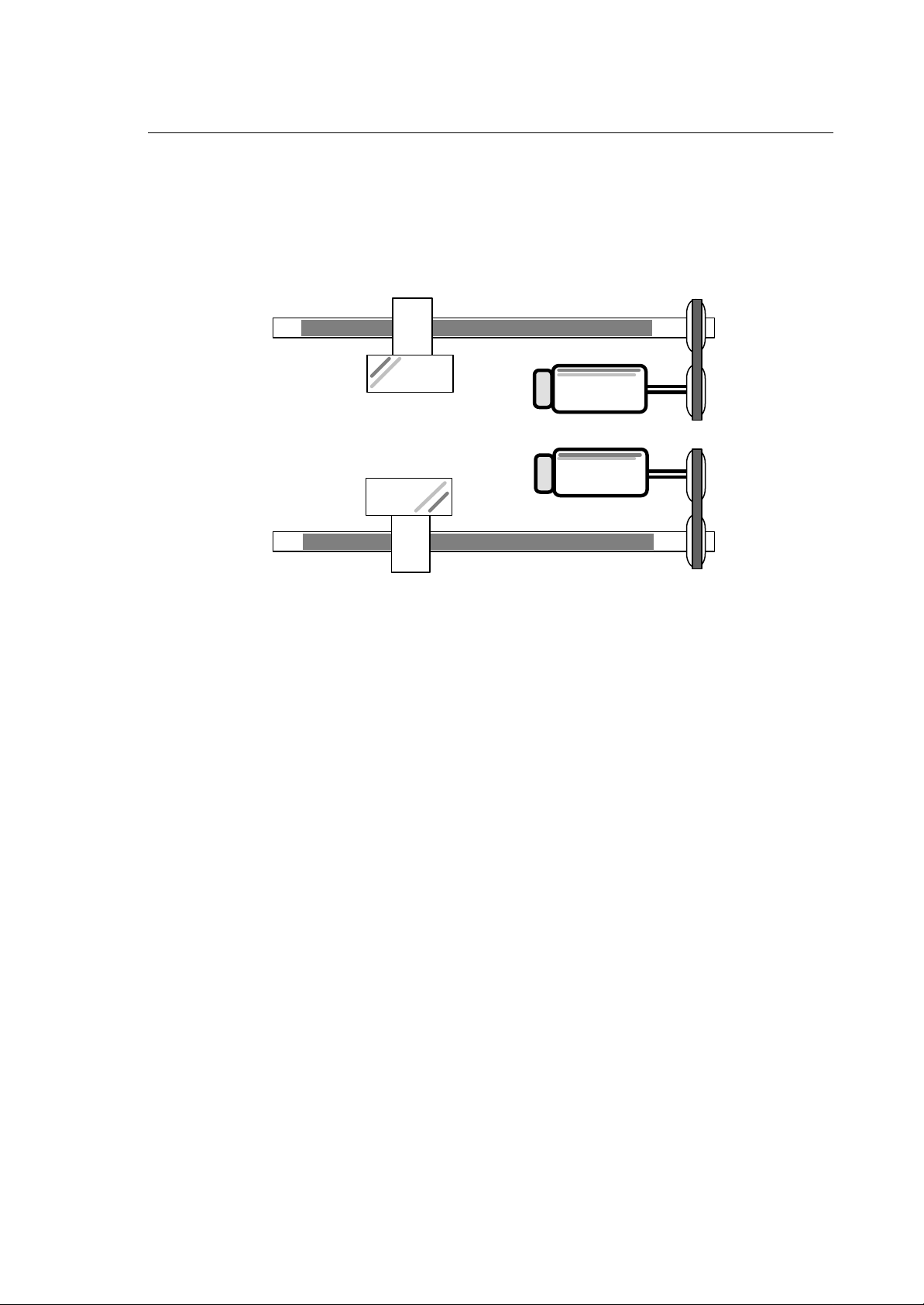
The figure illustrates how the wiring and/or the mechanical orientation permit to shift the counting
direction of the position transducer or the rotation of the motor between the master and the slave.
(T=transducer, M=motor)
MASTER
T
M
MASTER
T
M
SLAVE
SLAVE
T
M
T
M
1-14 10 Series CNC - AMP Software Characterization Manual (10)
Page 29
Chapter 1
General Concepts
DUAL AXES
Dual axes are two or more axes that follow an identical trajectory. A typical application of this feature
are multiple heads and multi-spindles.
Axis 1
Axis 2
Servo motor 1
Servo motor 2
With dual axes, only the programming of the master axis is mandatory.
The master-slave association must be defined by the program (refer to the UDA instruction in the
Programming Guide).
10 Series CNC - AMP Software Characterization Manual (10) 1-15
Page 30
Chapter 1
General Concepts
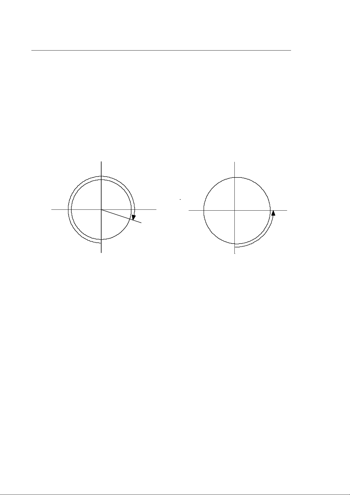
AXES WITH ROLLOVER
The axes with rollover are linear or rotary axes whose position is controlled by the system within a
range from zero to the value configured in the "Rollover pitch" field.
The sign of the quote programmed for the axis with rollover indicates the rotation direction:
• positive, rotation is in a clockwise direction
• negative, rotation is in an anticlockwise direction.
Examples:
270
180
CLOCKWISE
ROTATION
359.999
0
0
90
ANTICLOCKWISE
ROTATION
1-16 10 Series CNC - AMP Software Characterization Manual (10)
Page 31

Chapter 1
General Concepts
DIAMETER AXES
Diameter axes are coordinated axes that must be programmed and displayed with a 2 coefficient.
Example:
10 Series CNC - AMP Software Characterization Manual (10) 1-17
Page 32

Chapter 1
General Concepts
AUXILIARY AXES
Auxiliary axes are interpolated axes that are managed directly by the machine logic.
This feature permits to control those axes that do not take part in the machining process but support
auxiliary functions such as tool change chains, part change gates, etc.
10 Series CNC can control up to 6 simultaneous auxiliary axes coordinated with one another.
Auxiliary axes remain independent from machining axes and work in parallel with the machine tool
activities.
Example:
STEP POCKET
Step = Distance between two pockets
Pocket = Generic position of a tool in the tool magazine.
1-18 10 Series CNC - AMP Software Characterization Manual (10)
Page 33

SPINDLE AXIS
The spindle axis is the axis on which the tool is mounted during the machining cycle.
It may correspond to one of the machine axes.
SPINDLE
Chapter 1
General Concepts
Spindle axis with gears
Gears are speed reduction devices that can be installed between the motor and the spindle.
They enhance the motor performance by allowing to reach a high torque at medium and low speeds.
10 Series CNC MC can control spindles with as many as four different gears.
Prior to enabling a range it is necessary to configure the corresponding conversion factor between the
maximum voltage applied to the servo drive and the spindle velocity in rpm.
It is also possible to configure various "servo loop gain" values for each gear used by the spindle with
transducer during spindle orientation.
The parameters that configure this feature are:
• "Voltage for max RPM gear n"
• "Max speed for gear n".
10 Series CNC - AMP Software Characterization Manual (10) 1-19
Page 34

Chapter 1
General Concepts
Spindle axis ramp
10 Series CNC permits to configure whether the converter voltage is to vary uniformly (i.e. follow a
variation ramp) or make a step when the programmed rotation speed varies.
In spindle drives this control is carried out by an input compensation net.
By using the potentialities of the control unit and disactivating the compensation network it is
possible to optimize spindle functionality, mainly for threading cycles and orienting.
Examples:
Spindle axis without ramp.
Volt
+7.5
-7.5
Spindle axis with ramp.
Volt
+7.5
-7.5
rt
To establish a ramp it is necessary to configure the "reversal time", i.e. the time employed by the
spindle for switching from the maximum clockwise rotation speed to the maximum counter clockwise
rotation speed with the gear that allows the lowest voltage/speed ratio. Such gear must also be
configured.
If the ramp is not configured, these parameters must nevertheless be specified because they are
used during tapping and boring canned cycles.
1-20 10 Series CNC - AMP Software Characterization Manual (10)
Page 35

Chapter 1
General Concepts
Spindle with trasducer
The position transducer has two basic applications:
1. execution of threading and tapping cycles
2. spindle orientation to a defined position.
Spindle orientation
With 10 Series CNC spindle orientation is made possible by the $SORIENT machine logic function.
To compensate the offset between the transducer electrical zero and the spindle physical zero it is
possible to define an "Offset for spindle orientation" in the AMP.
The orientation cycle is carried out in interpolated mode and requires definition of the following
additional parameters to define the execution type.
Speed for Spindle Orientation
This parameter defines the threshold of speed below that the control enables spindle positioning.
If the orientation request is made when the spindle rotates at a higher speed, the system will take the
spindle to a lower speed before enabling the positioning cycle.
Acceleration for Orientation
This parameter specifies the spindle acceleration during orientation.
Since the gears and the loads affect the spindle response, it is advisable to assign to this parameter
a value smaller than the result of the following calculation:
Vm
60
where:
VM Is the "Voltage for max RPM" defined for the gear used for setting the "Spindle
reversal time".
TR Is the "Spindle reversal time".
*
TR*0.5
1
10 Series CNC - AMP Software Characterization Manual (10) 1-21
Page 36

Chapter 1
General Concepts
Shared Spindle
The spindle can be shared among several processes i.e. it can be declared in a “master” process
(Spindle field = Yes) and can be used by other processes simultaneously or not (Spindle field =
Shared).
The spindle has to be declared with the same identifier in all processes which can use it, whereas the
spindle's characterization parameters (Spindle section) need only be declared for the master
process.
In order to use the functions associated with the Spindle (the S functions) in a process on
programming level, the spindle has to be programmed in the process.
The management of the spindle's sharing among several processes is handled by the machine logic
which has to accept the programming of the spindle in a process if it is already controlled by another
process.
1-22 10 Series CNC - AMP Software Characterization Manual (10)
Page 37

Chapter 1
General Concepts
HANDWHEEL
The handwheel is a position transducer connected to one of the encoder inputs of the axes board. It
permits to move an axis by a distance that is proportional to the angle variation of the transducer
position.
To ensure maximum accuracy, it must comply with the following requirements:
1. The axis to be moved must be a configured axis.
2. The axis and the handwheel must be configured on the same board.
3. The handwheel encoder input must not be associated to any other configured axis.
4. The axis associated to the handwheel must be in idle status, i.e. it cannot be in motion.
5. If the handwheel is active it is not possible to carry out axis motion and axis enable/disable
operations directly on the axis.
6. Scale factor, representing the correspondence between handwheel impulses and distance to be
covered by the axis, must be chosen correctly.
Scale factor in fact, must have a value sufficient to grant the axis a jumpless movement even when
the handwheel is moved very fast.
For ex.: if the scale factor is very high therefore, if each minimum movement of the handwheel
corresponds to a great axis movement, the axis itself could not be able to execute that movement
correctly.
A SERVO ERROR may be generated in this situation.
Modification of the configured servo error value might be necessary in order to
optimize the hamdweel's function (see "POSITION ERROR WITHOUT VFF"
description in chapter 5 of this manual)
ENABLE/DISABLE of handwheel is prompted through logic functions (See PLUS Library Manual)
10 Series CNC - AMP Software Characterization Manual (10) 1-23
Page 38

Chapter 1
General Concepts
PART PROGRAM-LOGIC INTERFACE
The dialogue between the part program and the machine logic can be synchronous or asynchronous.
Synchronous mode
In this mode the part program makes a series of requests that must be acknowledged before
execution. These functions include:
• motion start/end M functions
• spindle S functions
• tool T functions
• pseudo axes
T and S follow predefined rules, whereas M functions are configurable and can be adapted to more
specific requirements (refer to Chapter 4, Section "M Codes").
Asynchronous mode
This mode exploits the possibility to render a series of machine logic variables visible to the part
program.
In the system configuration (see Chapter 3, Section "Logic Configuration") each variable must be
associated to a mnemonics (which will be used by the part program) and to an optional initialization
value.
These variables do not lose their contents when the system is switched off.
Language expansion
Logic global variables make it possible for the part program to acquire information that is not directly
accessible.
For example, the part program can learn the axis position by using an M function in order to
command the PLUS logic to carry out the acquisition, write the result in a shared variable (GW or
GD) and eventually authorize the part program to resume execution.
M100 (M to request the position of the W axis)
@ COORD_W variable shared with PLUS
Part program:
N001 M3 X123.4 Y321.5 M100
N002 E10=@COORDINATE_W
N003 Y(E10/2)
The logic can use global variables also as preset values or as non-volatile memory. To render these
variables inaccessible to the part program they must not be associated to a mnemonics.
1-24 10 Series CNC - AMP Software Characterization Manual (10)
Page 39

Chapter 1
General Concepts
PSEUDO AXES
Pseudo axes are written in the program without being associated to actual system axes. They are
used for requesting the machine logic to execute specific functions. They have the same functionality
of the PRELUDE M function.
Among the typical pseudo axes functions are: regulation of the water jet, management of secondary
spindles, etc.
VIRTUAL AXES
They are used to define some functionalities in AMP like axes virtualization.
The only parameter to be configured is the Axis ID.
They don't have neither name nor characteristics.
USER INTERFACE
10 Series CNC provides a series of predefined video pages that can be enlarged to occupy the full
screen or reduced to quadrants that display information about one topic. The size and contents of the
video pages and the sequence in which they are displayed can be configured in the AMP (refer to the
"Human Interface" chapter in this manual).
Logic display
With the $WSCREEN PLUS function it is possible to write alphanumeric and or semigraphic color
characters in the display areas reserved for the machine logic.
The machine logic can also be used for developing those texts that vary through system operation.
The SYNOPTIC EDITOR utility, that is also available in the PLUS environment (see Plus User
manual), permits the predefinition for each screen of graphics that will be loaded at system bootstrap.
OEM softkey
The dialogue between the operator and the machine can be facilitated by creating a tree of softkey
menus. The meaning of each softkey is application specific and can be established by the machine
logic.
The softkeys are the tools that permit to give a command, i.e. enable a given machine logic area.
Within each area it is therefore necessary to establish the procedures for command recognition and
execution. In some cases, activation of the softkey must be accompanied by a data input.
The interactions between the system and the operator can be developed by composing the video
screens that will be under machine logic control. Such screens prompt the operator to select a
course of action by means of the OEM softkeys and/or to input additional bits of information.
10 Series CNC - AMP Software Characterization Manual (10) 1-25
Page 40

Chapter 1
General Concepts
VARIABLE SERVO ERROR
The “Variable Servo Error” feature consists in a new logic control of the Servo Error during axis moves.
Usually the Servo Error is taken as absolute (i.e. it is directly compared with the axis tracking error).
This new feature allows to consider the Servo Error as an additional element to be added to the
theoretical tracking error, the axis is accumulating during its move based on the programmed
parameters (speed, gain, active or inactive VFF and VFF%).
During the move the algorithm calculates the theoretical axis error (based on its instantaneous speed)
to which it adds the configured delta plus the error accumulated during the delay due to the
positioning loop. Then this sum is compared to the tracking error.
The error accumulated during the feedback delay is calculated on the basis of the rapid acceleration
and is equal to:
Epsi_delay = rapid acc / (kv * 16.6666)²
Here 'rapid acc' and 'kv' are in the measurement units of the AMP.
THIS SUM IS ONLY CALCULATED ONCE AT START-UP AND NOT
CHANGED THEREAFTER.
In order to enable this feature you have to set the value of the movement Servo Error without VFF so
that it is smaller than the theoretical error calculated with maximum speed (the “Maximum Feed” field
in AMP) with VFF at zero. Once enabled, the algorithm becomes active for moves with as well as
without VFF and takes the delta value from the pertinent configured Servo Errors.
The algorithm becomes active at the start of a move if a comparison shows that the Servo Error value
is smaller than the theoretical maximum (which is calculated only once at start-up on the basis of the
data configured in AMP). If this condition is not met, the algorithm does not start and the Servo Error
is taken as an absolute value in the usual manner.
The algorithm does not become active if a VFF% equal to zero has been configured. If you want to
enable it on an axis which moves with the predefined error only, you have to enter a value different
from zero into the VFF% field.
The algorithm does not become active, when a VFF value equal to 100% has been configured on the
axis during a VFF move (the theoretical error is then zero, therefore the value of the configured Servo
Error is directly applied).
For Split axes the feature only works on the master axis.
The feature is not enabled for spindle type axes, axes with digital interface and with the Electronic
Cam feature.
Change of parameters by the Servo Monitor may change the Servo Error application algorithm.
1-26 10 Series CNC - AMP Software Characterization Manual (10)
Page 41

Chapter 1
General Concepts
Example 1 :
maximum feed = 4000 mm/min
acceleration = 300 mm/sec²
Servo Loop gain = 1
Position Error with VFF = 5 mm
Position Error without VFF = 5 mm
VFF% = 100
The theoretical error for comparison at maximum feed without VFF results as 4 mm.
Given that the “Position Error without VFF” is set to 5, the algorithm is not enabled and Servo Error
emergency is triggered, when the error exceeds 5 mm.
Example 2 :
maximum feed = 4000 mm/min
acceleration = 300 mm/sec²
Servo Loop gain = 1
Position Error with VFF = 1.5 mm
Position Error without VFF = 2.5 mm
VFF% = 100
As in the previous example the theoretical error is 4 mm.
For moves with VFF the “Position Error without VFF” is set to 1.5, but the algorithm is not enabled,
because VFF is equal to 100%. Hence Servo Error emergency is triggered when the error exceeds
1.5 mm.
For moves without VFF the “Position Error without VFF” is set to 2.5 (i.e. smaller than 4). Therefore
the algorithm is enabled and the error delta is 2.5 plus the delay equal to 300 / (16.666)² = 3.58. If the
current feed is 2000 mm/min, Servo Error emergency is triggered when the error exceeds 2 + 3.58 =
5.58 mm.
Example 3 :
maximum feed = 4000 mm/min
acceleration = 300 mm/sec²
Servo Loop gain = 1
Position Error with VFF = 1.5
Position Error without VFF = 2.5
VFF% = 50
As before the theoretical error for comparison is 4 mm.
10 Series CNC - AMP Software Characterization Manual (10) 1-27
Page 42

Chapter 1
General Concepts
For moves with VFF the error delta with VFF is 1.5. Assuming a feed of 2000 mm/min is
programmed, the theoretical error is 1 mm (as the current feed will be with VFF at 50%). Therefore
the Servo Error emergency triggers when the error exceeds 1 + 1.5 + 300 / (16.666)² = 3.58 mm.
For moves without VFF the error delta is 2.5. With a feed of 3000 mm/min the Servo Error emergency
triggers when the error exceeds 3 + 2.5 +1.08 = 6.58 mm.
END OF CHAPTER
1-28 10 Series CNC - AMP Software Characterization Manual (10)
Page 43

Chapter
2
AMP
AMP (Adjustable Machine Parameters) is one of the utilities installed in the OEM Utility partition of
the system. AMP allows the user to set the parameters that define the various processes to be run
by the machining centre.
To enter the AMP utility, press the softkey UTILITY in the general 10 Series CNC screen.
HELP
OEM SOFTKEYS
UTILITY
10 Series CNC general screen
AMP utility selection
AMP
Access to the AMP utility is also possible with the system in emergency, i.e. by holding down key
[F1].
SOFTKEY
There are seven softkeys to handle the configuration environment:
by pressing the right most softkey the operator can select the menu line that contains the desired
item with a loop cycle (the selected line is displayed in a different colours)
the middle softkeys correspond to the items of the selected line. By pressing one of these softkeys,
the operator can access the desired data entry
by pressing the left most softkey the operator can always return to the main menu.
10 Series CNC - AMP Software Characterization Manual (06) 2-1
Page 44

Chapter 2
AMP
AMP main menu
When AMP is activated, the first displayed menu is shown in the following picture:
date: dd/mm/yy
ACTIVATED AMP RUNNING AMP
time: hh:mm:ss
COMPILED
Y
N
INFORMATION
BOX
CONFIGURATION
STATUS
Configuration
0 - 3
Adjust Machine Parameters
SELECTED AMP
3 0 0
-- A M P D I R E C T O R Y L I S T --
0 - DEFAULT
1 - DEFAULT
2 -
3 -
CURSOR
ACTIVATE SELECT
BACKUP
EDIT COMMENT
DELETE PRINT
SOFTKEYS
HELP
EXIT
AMP utility allows to manage 4 different configurations; this is very useful to switch from one
configuration to another one.
The configurations are numbered from 0 to 3 and can associate a comment (that is displayed close
the configuration number).
The desired configuration can be selected using the arrows keys:
The blue cursor will highlight the request configuration.
2-2 10 Series CNC - AMP Software Characterization Manual (06)
Page 45

Chapter 2
AMP
INFORMATION BOXES
• Selected AMP
It is the selected configuration to be modified
• Activated AMP
It shows the configuration that will be used on the next power up.
• Running AMP
It shows the configuration that was used during the last (current) power up.
CONFIGURATION STATUS
• Y The AMP configuration has been compiled successfully
• N The AMP configuration has not been compiled or the compilation was not ended
successfully
• (Empty) The AMP directory is void.
CURSOR AND CONFIGURATION
• They highlight one of the 4 possible configurations.
SOFTKEYS
• They allows to activate the possible functions. They will be explained in detail in the following
pages.
Help
At any moment during the AMP configuration, the user can display additional information about a
certain parameter or sub menu by selecting the HELP softkey. This help text is displayed within a
window on the right side of the screen and varies according to the context in which it has been
activated: if the user has selected the HELP softkey when a menu is on the screen, the help text will
contain information about that specific menu (data entries and associated parameters); if Help is
activated when a data entry is on the screen, the help text will contain information about parameter
values (range, restrictions, measuring, unit, etc.).
10 Series CNC - AMP Software Characterization Manual (06) 2-3
Page 46

Chapter 2
HARDWARE
LOGIC CONF
AMP
Activate
Activates the configuration (0-3) selected via the arrow keys and highlighted by the blue bar.
The configuration number is displayed in the central information box.
This configuration will be used by 10 Series CNC on the next power up.
Trying to activate a configuration that was not previously compiled, the error
"AM155 AMP directory can not be activated: binary file does not exist" is
generated.
To get information regarding the compilation, see also the section regarding the
SELECT softkey.
Select
Opens the characterization, this will be ended pushing the EXIT softkey.
See also the "Enter/Exit the characterization" paragraph.
T
SELEC
first line
SELECT PROCESS
BACKUP
PROCESS CONFIG
AXIS CONFIG
AMP main menu
Characterization menu
OPTIONS
HUMAN INTERF
HELP
EXIT
third line
second line
2-4 10 Series CNC - AMP Software Characterization Manual (06)
Page 47

Chapter 2
AMP
Characterization menu softkeys
The first line of the characterization menu included the following softkeys for global parameter
configuration (chapter 3).
• HARDWARE data entry Hardware configuration of the system
• GENERAL INFO data entry General information for configuration
(measuring unit, number of configurable processes, logic
variables)
• LOGIC CONF sub menu (LOGIC CONFIGURATION)
• BOOLEAN VAR (Booleans variables)
• SHORT VAR (Short variables)
• DOUBLE VAR (Double variables)
• AUX GEN INFO (Auxiliary axes general information)
• SELECT AUX (Auxiliary axes selection)
• AUX CHARACT (Auxiliary axes characterization)
• PHYSICAL CONN (Physical connection)
• AXIS CALIBR (Axis calibration)
• Option sub-menu
• DOS REAL-TIME (Real-time DOS Interface)
• UND USER DOS (End User Dos utility)
• DOS GRAPHICS (DOS Graphic Utility Interface)
• HELP Help text
The second line includes the following softkeys associated to process related functions.
• SELECT PROCESS data entry (PROCESS SELECT)
It is meaningful for multi process systems only and allows
to select the process to be configured. All the information
that follows is related to the selected process.
10 Series CNC - AMP Software Characterization Manual (06) 2-5
Page 48

Chapter 2
AMP
• PROCESS CONFIG sub-menu (PROCESS CONFIGURATION)
• GTL (High level geometry)
• VIRTUAL AXES (Virtual axes)
• E PARAMETERS (E variables)
• USER VARIABLES (User variables)
• PRO CHAR (Process characterization)
• PROC VARIABLES (Process variables)
• PROGR CHAR (Program characteristics)
• M CODE (M code)
• G CODE (G code)
• AXIS CONFIG sub-menu (CO-ORDINATE AXES CONFIGURATION)
• AXES GEN INFO (Co-ordinate axes general information)
• PSEUDO AXES (Pseudo axes)
• SPINDLE (Spindle characterization)
• PROBING (Touch probe)
• SELECT AXIS (Axis selection)
• AXIS CHARACT (Axis characterization)
• AXIS CALIBR (Axis calibration)
• PHYSICAL CONN (Physical connection)
• HUMAN INTERF sub-menu (OPERATOR INTERFACE)
• HI GEN INFO (Operator interface general information)
• ADD SCR CONFIG (Additional screen configuration)
• COMMON SCREEN Not available
• PROCESS SCREEN (Process screen cycle)
• SELECT MENU (OEM menu selection)
• OEM SK CONFIG (OEM softkey configuration)
• SELECT DE (OEM data entry selec tion)
• DE CONFIG (OEM data entry configuration)
• PPDIR CONFIG (Part program directory configuration)
The third line of the menu includes the EXIT softkey
• EXIT (Exit for the characterization session).
2-6 10 Series CNC - AMP Software Characterization Manual (06)
Page 49

Chapter 2
AMP
Operativity notes
When the user has selected the desired data entry with the proper softkeys, he can start defining the
associated parameters with the alphanumeric keyboard.
The cursor is automatically positioned on the value field of each parameter. The operator can accept
the displayed value or he can insert a new one. If necessary, the operator can move the cursor by
using the arrow keys.
The correct range of values for each parameter is shown in the Help window that the operator can
display by pressing the HELP softkey.
In some cases the permissible range is displayed as a list (for example, user variable names, coordinate axis names, etc.).
For each entered value, AMP performs range and congruency checks. In case of mistakes, the
relevant error message is displayed (see Appendix A) and the cursor remains on the wrong
parameter.
Some data entries can be listed on more than one screen page. The user can display the various
pages by using [Pg Dn] and [Pg Up] keys.
Data Entry Storage
Once the data entry has been completed, the user can confirm and store it in the AMP files, by
pressing the [Enter] key.
To abort a data entry it is possible to press the [Esc] key.
10 Series CNC - AMP Software Characterization Manual (06) 2-7
Page 50

Chapter 2
AMP
ENTER/EXIT THE CHARACTERIZATION
10 Series CNC manages up to 4 "on line" configurations.
When the SELECT softkey is used to modify the selected configuration (0, 1, 2 or 3), this is copied in
a work directory.
All the changes will be made in the work directory.
Following configuration (press EXIT), there are 3 alternatives:
1. Perform the secondary calculations transforming the information entered (source files) into a
configuration that may be used by the bootstrap (binary files).
2. Save the data entered without performing the secondary calculations (this may also be useful in
cases where errors that cannot be eliminated at the time are signalled during the secondary
calculations but you want to save the changes made in any case). In this case, any binary files
generated previously are lost and care must be taken because, if the AMP directory was the
active one, on rebooting the system will not find the binary configuration files and the control will
have to be started in emergency mode to generate and activate an AMP configuration.
3. Do not save the new configuration. In this case any changes made are lost. If there were binary
files for the previous configuration, these will be maintained as the source files from which they
were generated have not been changed. You are advised to use this exit mode when entering the
configuration for consultation to avoid losing the binary files.
Remember the meaning of the terms Source and Binary for the AMP utility:
SOURCE FILES contain the information entered with the data entry.
BINARY FILES files generated by the secondary calculations and actually used by 10
Series CNC to configure the machine on starting (BOOTSTRAP).
Examples:
• If you press SELECT (see figure) configuration no. 1 becomes the working configuration.
AMP directory Working directory
AMP0
Select
AMP1
AMP2
EXIT
AMP3
2-8 10 Series CNC - AMP Software Characterization Manual (06)
Page 51

Chapter 2
HELP
EXIT
-- EXIT --
Translate new parameters? (Y/N)
Y
HELP
EXIT
-- EXIT --
Translate new parameters? (Y/N)
N
-- SAVE --
Save new configuration? (Y/N)
AMP
• After changing the configuration, press EXIT.
The system asks if the secondary calculations are to be made. If the answer is "Y", the binary files
will be generated (if there are no errors, in which case you stay in the configuration stage); this is the
case of alternative 1.
Characterization menu
New file generation data entry
On the other hand, if the answer is "N", the system will ask if you want to save the changes to the
source files or not.
Characterization menu
New file generation data entry
If the answer in the SAVE data entry is "Y", the changes become operative (case 2). If the answer is
"N", any changes made will be lost (case 3).
10 Series CNC - AMP Software Characterization Manual (06) 2-9
If the system is powered off while in the process of configuring a selected AMP
directory, any changes made will be lost.
Page 52

Chapter 2
Data Entry Edit Comment
-- EDIT AMP DIRECTORY COMMENT --
AMP main menu
EDIT COMMENT
DELETE
Backup Data Entry
BACKUP
-- B A C K U P --
AMP main menu
SELECT
AMP
Edit Comment
This softkey in the AMP main menu allows to insert/modify the comment associated to the
configuration.
This comment must be used to identify a specific configuration (0-3) in the AMP DIRECTORY LIST.
#
NOTE:
# identifies the number of the current characterization
To exit the data-entry, push EDIT COMMENT softkey again.
Backup
This softkey enter in the Backup utility.
This utility allows to save, restore or copy an AMP configuration data-entry.
:
From
To
:
2-10 10 Series CNC - AMP Software Characterization Manual (06)
Page 53

Where:
-- DELETE --
Confirm delete AMP directory
Y/N) ?
#
N
From: It is the source directory.
It is one of the four AMP Directories; in this case it must be a number between 0
and 3.
To: Destination directory:
It is one of the four AMP directories (number between 0 and 3) or another
directory defined by a complete path (i.e. a:\amp).
Obviously the BACKUP utility can be used to save or restore or copy configuration data.
Delete
DELETE softkey allows to delete an AMP configuration.
EDIT COMMENT
DELETE
AMP main menu
Chapter 2
AMP
Data entry delete
(
Print
PRINT
This utility is dedicated to printing of various configurations inside AMP memorised in directories:
E:\AMP1AMP0,...AMP1,...AMP2,...AMP3.
AMP main menu
Main screen print utility
The utility can supply a print of each data-entry (with its frames and data inserted). Possibility to
choose directory and process to which printed data must refer to, is envisaged; comments relative to
the contents of the various directories are available on the utility's main display.
10 Series CNC - AMP Software Characterization Manual (06) 2-11
Page 54

Chapter 2
AMP
Data entries selectable in AMP are divided in homogeneous groups and for each of these groups it is
possible to confirm or enable printing; the final print out will always be preceded by the hardware and
software characteristics of the machine and by the information entered in the "Hardware" and
"General" data entries.
The utility's output can be memorised in a file (path defined by user) or sent directly to the printer.
A M P D I R E C T O R I E S
AMP0: ........
AMP1: ........
AMP2: ........
AMP3: ........
Printing amp: #
SELECT DIR SELECT PROCESS SELECT PATH PRINT ABORT
NOTE:
# represents the number of the AMP selected.
HELP
EXIT
2-12 10 Series CNC - AMP Software Characterization Manual (06)
Page 55

Chapter 2
AMP
Select dir
It is possible to select the directory where the configuration to print resides, through the "SELECT
DIR" data-entry. In case no selection is made, data will refer to the last directory configured in amp.
Should the selected directory be empty or wrong, an error message is signalled.
A M P D I R E C T O R I E S
AMP0: ........
AMP1: ........
AMP2: ........
AMP3: ........
-- SELECT DIRECTORY --
- directory to be print:_
Printing amp: #
SELECT DIR SELECT PROCESS SELECT PATH PRINT ABORT
Directory to be print
Description: select the AMP directory to be print.
Range: 0..3
Default value: none
Unit: none
On accessing the PRINT utility, the data with which to perform printout of the
AMP directory always refer to the AMP number displayed in the "Printing amp"
box.
HELP
EXIT
10 Series CNC - AMP Software Characterization Manual (06) 2-13
Page 56

Chapter 2
AMP
Select process
At the selection of the mentioned data entry panel the number of configured processes is displayed.
If the print of the data referring to all configured processes is required, the character '*' must be
inserted instead of the number of the process.
If no selection is done, the data will refer to the first process.
PROCESS number configured : 1
-- SELECT PROCESS --
- selected process:_
Printing amp: #
SELECT DIR SELECT PROCESS SELECT PATH PRINT ABORT
Select process
Description: select process (or processes) whose data must be printed.
Range: from 1 up to the maximum number of configured processes
Default value: none
Unit: none
HELP
EXIT
2-14 10 Series CNC - AMP Software Characterization Manual (06)
Page 57

Chapter 2
Select path
Using the "Select path" data-entry, the set of information to be printed can be defined.
The various data-entry that can be configured in AMP have been subdivided in the following groups:
- PROCESS PATH - E PARAMETERS
- HUMAN PATH - M CODES
- AXIS PATH - PLUS VARIABLES
- OPTIONALS PATH - AXIS CALIBRATION
- USER VARIABLES
-- PATH SELECTION --
- process path :
- human path :
- axis path :
- optional path :
- user variables :
- E parameters :
- M codes :
- plus variables :
- axes
calibration
:
AMP
HELP
SELECT DIR SELECT PROCESS SELECT PATH PRINT ABORT
EXIT
The above-mentioned groups respectively include:
- PROCESS PATH:
- Process characterization
- User variables definition
- Process variables
- Program characterization
- G codes
- Pseudo axes
- Virtual axes configuration
- Probing
- Geometrical Technological Language
10 Series CNC - AMP Software Characterization Manual (06) 2-15
Page 58

Chapter 2
AMP
- HUMAN PATH:
- Hi general information
- Process screen loop
- Additional screen configuration
- PPDIR configuration
- Select OEM SK menu
- SK configuration
- Select OEM data entry
- OEM data entry configuration
- AXIS PATH
- Auxiliary axis general information
- Auxiliary axis characterization
- Physical connections
- Co-ordinate axes general information
- Slave axes general information
- Spindle
- Co-ordinate axis characterization
- Co-ordinate axis D.S.I. characterization
- Physical connections
- Slave axis characterization
- Slave axis D.S.I. characterization
- Physical connections
- OPTIONALS PATH:
- Dos Real-Time
- Dos Graphics
- End User Dos
- USER VARIABLES:
- User variables set up
- E PARAMETERS
- E parameters set up
- M CODES:
- M codes
- PLUS VARIABLES:
- Boolean variables set up
- Short variables set up
- Double variables set up
- AXES CALIBRATION:
- Axis calibration
NOTE:
D.S.I. is the abbreviation of Digital Standard Interface.
2-16 10 Series CNC - AMP Software Characterization Manual (06)
Page 59

Chapter 2
AMP
Print
The print starts when the "SELECT DEVICE" data-entry is confirmed (PRINT softkey):
The name of the device to which direct the output of the utility must be introduced using this data-
entry: this output device can be a file or a printer, both local or remote.
A:, E:, PRN are admitted as local devices; H:,....Z:, LPT1, LPT2, LPT3, if connected, are admitted as
remote devices.
If the remote printer LPT1 is not connected, it coincides with PRN.
A M P D I R E C T O R I E S
AMP0 : ........
AMP1 : ........
AMP2 : ........
AMP3 : ........
-- SELECT DEVICE --
- device: a:\prt\printfil.asc
HELP
SELECT DIR SELECT PROCESS SELECT PATH PRINT ABORT
EXIT
NOTE:
In this case the directory PRT on floppy must already exist, otherwise an error will be returned.
Abort
Pressing the ABORT softkey an already started printing process can be interrupted.
If the selected device is a file, the data referring to the data-entries read before this softkey pressing
will be stored in the file.
10 Series CNC - AMP Software Characterization Manual (06) 2-17
Page 60

Chapter 2
AMP
AMP print utility error messages
_______________________________________________________________________________
Code Message description and recovery action
_______________________________________________________________________________
PR024 Seek error
It is generated when a positioning error occurs during a file reading or waiting
phase.
PR025 Open file error
It is generated when an anomaly occurs during the opening phase of a file used
by the print utility.
PR026 Read file error
It is generated when a reading operating in one of the AMP data base files is not
successful.
PR027 Write file error
It is generated when a writing operation on an output file is not successful.
PR028 Memory allocation error
It is generated when an internal dynamic memory allocation fails.
PR030 Data-entry not found
It is generated when the information related to a data-entry to be printed are not
found in the AMP files.
PR03 Unknown device
It is generated when the name of the output device selected with the "SELECT
DEVICE" data-entry in not of the admitted devices.
PR032 Empty directory
It is generated when the AMP directory selected through the "SELECT
DIRECTORY" data-entry is empty.
PR033 Process not configured
It is generated when the process selected in the "SELECT PROCESS" data-entry
is not configured.
PR034 Output file not found
It is generated when an anomaly occurs opening the output print utility file, or
when its path name is wrong.
2-18 10 Series CNC - AMP Software Characterization Manual (06)
Page 61

Chapter 2
_______________________________________________________________________________
Code Message description and recovery action
_______________________________________________________________________________
PR035 Protected diskette
It is generated when the output device is a floppy and is write protected.
PR036 Driver not ready
It is generated when the output floppy is not inserted.
PR037 Print fault
It is generated when the output printer is not connected.
PR038 Print out of paper
It is generated when the output printer is out of paper.
PR040 Value out of range
Value out of permissible range
AMP
PR041 AMP configuration can not be read
It is generated when a process has been declared in AMP but is not configured:
i.e. its presence has been set in the "GENERAL INFO" AMP data-entry, but it
has been selected using the "SELECT PROCESS" AMP data-entry.
10 Series CNC - AMP Software Characterization Manual (06) 2-19
Page 62

Chapter 2
AMP
END OF CHAPTER
2-20 10 Series CNC - AMP Software Characterization Manual (06)
Page 63

Chapter
3
LOGIC CONF
AMP main menu
GLOBAL PARAMETERS CONFIGURATION
This chapter describes all the parameters related to the general system configuration: peripherals,
memory, devices, processors, Logic information, optional features in the OEM partition, program
verification, etc.. This aspect of the configuration is divided into four sections: Hardware, General
Information, Logic Axis, Options configuration.
NOTE:
The parts described in this chapter are those that can be accessed from the first line of the
characterization menu and are common to all the systems comprising the 10 Series CNC, namely:
10/310, 10/565 and 10/585.
An exception to this is the data entry for the Hardware configuration of the 10/310 system, on
account of this, a distinction will be made between this system and the 10/565 and 10/585 systems.
SELECT
BACKUP
Characterization menu
HARDWARE
SELECT PROCESS
After the selection, the screen shows a characterization menu which allows the operator to access
the desired parameters list.
NOTE:
For each parameter a brief description is provided, with the range, unit of measurement and the
default value.
GENERAL INFO
PROCESS CONFIG
AXIS CONFIG
OPTIONS
HUMAN INTERF
HELP
EXIT
10 Series CNC - AMP Software Characterization Manual (10) 3-1
Page 64

Chapter 3
Global Parameters Configuration
HARDWARE (10/310, 10/110 AND 10/510 SYSTEM)
Status :
-- H A R D W A R E C O N F I G U R A T I O N --
- board code numbe : 11
- position loop clock : 3.0
- serial line device (port 1) : 0
- serial line device (port 2) : 0
- system clock : 10
- broken wire : Disable
- DSI baud rate
(Mbit/s)
- TX power : 6
: 2
HARDWARE GENERAL INFO LOCAL CONFIG OPTIONS HELP
SELECT PROCESS PROCESS CONFIG AXIS CONFIG HUMAN
INTERFACE
Board code number
Description: determines code number of the board.
Board code no. Board type Sistem type
11 3 transducers 4 converters 10/310 and 10/110
12 4 transducers 6 converters 10/310 and 10/110
13 6 transducers 8 converters (only for 10/310) 10/310
14 6 transducers 8 converters 10/510 with OS_8510
15 4 transducers 6 converters 10/510 with OS_8510/1
16 8 axes DSI no transducers no converters 10/510 with OS_8510/2
17 8 axes DSI + 2 transducers + 2 converters 10/510 with OS_8510/3
18 5 axes DSI 10/510 with OS_8510/4
19 Reserved
20 Reserved
Range: 11/12/13/14/15/16/17/18/19/20
Default value: 11
Unit type: none
EXIT
3-2 10 Series CNC - AMP Software Characterization Manual (10)
Page 65

Chapter 3
Global Parameters Configuration
Position loop clock
Description: specifies the amount of time before the position loop is closed.
Range: min 0.2/max 10 (with OS_8510/2 OS_8510/3 and OS_8510/4 min2/max 10)
Default value: 5.0 with resolution 0.1
Unit type: msec.
NOTE:
The value set for "Position loop clock" must be a multiple of the value assigned the "System clock".
Serial line device (port 1)
Description: it determines the driver type which can handle the serial port 1.
Currently only the driver for handling the Teach Pendant (1), the asynchronous serial driver (2) or the
serial driver for the DAC drives (3) are available.
Range: min 0/max 3
Default value: 0
Unit type: none
Serial line device (port 2)
Description: determines the type of driver that can manage serial port 2.
The only drivers currently envisaged for management of serial port 2 are the Teach Pendent (1) and
the Asynchronous Serial Driver (2) and the serial driver for the DAC drives (3) are available.
Range: min 0/max 3
Default value: 0
Unit type: none
If the driver a for the Teach Pendant (1) is enabled for both serial lines,
the driver will only be mounted on serial line 1.
If the driver for the DACs (3) is enabled for both serial lines, the driver
will only be mounted on serial line 1.
System clock
Description: the system clock.
Range: min 2/max 10
Default value: 5.0 with resolution 0.1
Unit type: msec.
10 Series CNC - AMP Software Characterization Manual (10) 3-3
Page 66

Chapter 3
Global Parameters Configuration
Broken wire
Description: allows you to enable or disable broken wire control on all axes.
Range: ENABLE/DISABLE
Default value: DISABLE
Unit type: none
DSI baud rate
(communication speed of the standard digital interface)
Description: defines the transmission speed for the boards 8520/2 /3 and /4. Otherwise this value is
ignored.
Variation field: 2 or 4
Default Value: 2
Units: Mbit/s.
Tx power
(transmission power)
Description: defines the transmission power of the optical signal in output of the boards. Otherwise
this value is ignored.
Range: min 1 max 6
Default Value: 6
Units: none
3-4 10 Series CNC - AMP Software Characterization Manual (10)
Page 67

HARDWARE (10/565 AND 10/585 SYSTEMS)
Status :
-- H A R D W A R E C O N F I G U R A T I O N --
- I/O board code number : 2
- axes board 0 code number : 1 position loop clock : 5.0
- axes board 1 code number : 0 position loop clock : 5.0
- axes board 2 code number : 0 position loop clock : 5.0
- axes board 3 code number : 0 position loop clock : 5.0
- serial line device (port 1) : 0
- serial line device (port 2) : 0
- system clock : 10
Chapter 3
Global Parameters Configuration
HARDWARE GENERAL INFO LOCAL CONFIG OPTIONS HELP
SELECT PROCESS PROCESS CONFIG AXIS CONFIG HUMAN
INTERFACE
In this data entry, users can define the system's hardware configuration data.
Status :
-- D. S. I. H A R D W A R E C O N F I G U R A T I O N --
- axes board 0 D.S.I. baud rate (Mbit/s):
2
- axes board 1 D.S.I. baud rate (Mbit/s):
2
- axes board 2 D.S.I. baud rate (Mbit/s):
2
- axes board 3 D.S.I. baud rate (Mbit/s):
2
Tx power: 6
Tx power: 2
Tx power: 2
Tx power: 2
1 of 2
EXIT
2 of 2
10 Series CNC - AMP Software Characterization Manual (10) 3-5
Page 68

Chapter 3
Global Parameters Configuration
HARDWARE GENERAL INFO LOCAL CONFIG OPTIONS HELP
SELECT PROCESS PROCESS CONFIG AXIS CONFIG HUMAN
INTERFACE
EXIT
3-6 10 Series CNC - AMP Software Characterization Manual (10)
Page 69

Chapter 3
Global Parameters Configuration
I/O board code number
Description: characterises the I/O board. The board is integrated, therefore any value from 1 to 4 will
be accepted.
Range: 1/2/3/4
Default value: 2
Unit type: none
Axes board # code number (# = 0..10)
Description: it defines the axes board code:
I/0 board code Board type
0 None
1 OS 8020/4 (6 axes, 6 trasducers, 6 converters)
2 OS 8020/5 (4 axes, 3 trasducers, 4 converters)
3 OS 8020/6 (6 axes, 6 trasducers, 6 converters)
4 OS 8020/7 (4 axes, 3 trasducers, 4 converters)
5 OS 8025/2 (6 axes, 6 trasducers, 6 converters)
6 OS 8025/3 (4 axes, 3 trasducers, 4 converters)
9 OS 8026 (D.S.I., 0 trasducers, 0 converters)
10 OS 8026/2 (D.S.I., 3 trasducers, 1 converter)
Range: 0/1/2/3/4/5/6/9/10
Default value: 1 (axes board 0), 0 (axes board 1..10)
Unit type: none
Position loop clock
Description: it specifies how many times it takes for position loop clock.
Range: min 0.2/max 10
Default value: 5 with resolution 0.1
Unit type: msec
Serial line device (port 1)
Description: it determines the driver type which can handle the serial port 1.
Currently only the driver for handling the Teach Pendant (1), the asynchronous serial driver (2) or the
serial driver for the DAC drives (3) are available.
Range: min 0/max 3
Default value: 0
Unit type: none
10 Series CNC - AMP Software Characterization Manual (10) 3-7
Page 70

Chapter 3
Global Parameters Configuration
Serial line device (port 2)
Description: it determines the driver type that handles serial port 2.
The only drivers currently envisaged for the management of serial port 2 are the Teach Pendent (1)
and the Asynchronous Serial Driver (2) and the serial driver for the DAC drives (3) are available.
Range: min 0/max 3
Default value: 0
Unit type: none
If the driver a for the Teach Pendant (1) is enabled for both serial lines,
the driver will only be mounted on serial line 1.
If the driver for the DACs (3) is enabled for both serial lines, the driver
will only be mounted on serial line 1.
System clock
Description: it is the system clock.
Range: min 1/max 10
Default value: 10 with resolution 0.1
Unit type: msec.
Axes board (0..3) D.S.I. baud rate
(Dialog speed of the standard digital interface)
Description: defines the transmission speed of the board (0..3), only if a D.S.I. board. The value is
ignored otherwise.
Range: 2 or 4
Default value: 2
Unit type: Mbit/s
Tx power
(Transmission power)
Description: it defines the strength of the optical signal coming out of the D.S.I. boards
Range: min. 1/max. 6
Default value: 6
Unit type: none
3-8 10 Series CNC - AMP Software Characterization Manual (10)
Page 71

GENERAL INFORMATION
Status :
-- G E N E R A L I N F O R M A T I O N --
- configuration measuring unit : MM
- Number of process : 1
- Search in memory : 0
- Logic Boolean variables num. : 0
- Logic short variables num. : 0
- Logic double variables num. : 0
- Tool preset modality : 0
Chapter 3
Global Parameters Configuration
HARDWARE GENERAL INFO LOCAL CONFIG OPTIONS HELP
SELECT PROCESS PROCESS CONFIG AXIS CONFIG HUMAN
INTERFACE
EXIT
This data entry allows the user to define general information such as measuring unit (millimeters or
inches), number of processes (only for the multi-process unit), number of variables involved in the
communication between the part program and the logic, etc.
Configuration measuring unit
Description: It is the measuring unit of the parameters marked with " * " in the subsequent data
entries. It is also the default measuring unit of the control.
Range: INCHES/MM
Default value: MM
Unit type: none
Number of process
Description: It defines the number of processes to be configured. In mono-process systems, only the
first process can be configured. In the multi process system, processes must be configured in
sequential mode, starting from process 1.
Range: from 1 to 20 for multi process systems
Default value: 1
Unit type: none
10 Series CNC - AMP Software Characterization Manual (10) 3-9
Page 72

Chapter 3
Global Parameters Configuration
Search in memory
Description: It allows you to enable or disable the search in memory feature.
Range: 0 disabled, 1 enabled
Default value: 0
Unit type: none
Logic Boolean variables number
Description: It defines the number of Boolean type variables that will be used to achieve the
handshaking between the part program and the logic. According to this number, the system will ask
for the name and value of each variable.
Range: min 0/max 128
Default value: 0
Unit type: none
Logic short variables number
Description: It defines the number of Short type variables that will be used to achieve the handshaking
between the part program and the logic. According to this number, the system will ask for the name
and value of each variable.
Range: min 0/max 128
Default value: 0
Unit type: none
Logic double variables number
Description: It defines the number of Double type variables that will be used to achieve the
handshaking between the part program and the logic. According to this number, the system will ask
for the name and value of each variable.
Range: min 0/max 64
Default value: 0
Unit type: none
Tool preset modality
Description: It indicates how the tool offsets are calculated during the preset operation: if it is 0 the
offset value is always positive; if it is 1 the offset is calculated as a positive or negative value
depending on the set preset value and the axis position.
Range: 0/1
Default value: 0
Unit type: none
3-10 10 Series CNC - AMP Software Characterization Manual (10)
Page 73

Global Parameters Configuration
EXIT
AXIS CONFIG
BOOLEAN VAR
SHORT VAR
DOUBLE VAR
*
LOGIC CONFIGURATION
By selecting this softkey, the operator can access the following submenu:
LOGIC CONF
Characterization menu
Logic configuration sub menu
HELP
AUX GEN INFO SELECT AUX
PHYSICAL CONN
This submenu allows the user to configure all the logic related information.
The following pages illustrate each submenu and data-entry which is presented in the logic
configuration.
AXIS CALIBRAUX CHARACT
Chapter 3
Boolean Variables
Boolean Var
(Variabili boolean)
Status :
-- B O O L E A N V A R I A B L E S S E T U P --
name (max 11 ch.) address (0-255) index (0-15) value (0-1)
- 0 : 0 0
- 1 : 0 0
- 2 : 0 0
- 3 : 0 0
- 4 : 0 0
- 5 : 0 0
- 6 : 0 0
- 7 : 0 0
- 8 : 0 0
- 9 : 0 0
- 10 : 0 0
- 11 : 0 0
Page 1 of n
BOOLEAN VAR SHORT VAR DOUBLE VAR HELP
AUX GEN INFO SELECT AUX AUX CHARACT PHYSICAL CONN AXIS CALIBR
EXIT
NOTE:
*
"n" varies in function of the number of Boolean variables configured.
10 Series CNC - AMP Software Characterization Manual (10) 3-11
Page 74

Chapter 3
Global Parameters Configuration
This data entry allows the configuration of the boolean type variables used by the part program to
communicate with the logic. Each variable is defined by means of a logical name (whose first
character must be " @ "), the address and index values and an initial value. If the logical name is only
"@", the boolean variable is initialized but it is not known by the part program. The number of
variables depends on the related value set in the "General Info" data entry.
Name
Description: it contains the name of a boolean type variable. The first character must be " @ ".
Range: 11 char.
Default value: none
Unit type: none
Address
Description: it is the boolean variable number.
Range: min 0/max 255
Default value: 0
Unit type: none
Index
Description: it is the bit number inside the boolean variable.
Range: min 0/max 15
Default value: 0
Unit type: none
Value
Description: it is the initial value of a boolean type variable. This value will be assigned to the
associated variable at each power up.
Range: 0/1
Default value: none
Unit type: none
3-12 10 Series CNC - AMP Software Characterization Manual (10)
Page 75

Short Variables
0
0
0
0
0
0
0
0
0
0
0
0
*
Status :
-- S H O R T V A R I A B L E S S E T U P --
name (max 11 ch.) address (0-255) value (-32767+32767)
- 0 :
- 1 :
- 2 :
- 3 :
- 4 :
- 5 :
- 6 :
- 7 :
- 8 :
- 9 :
- 10 :
- 11 :
Chapter 3
Global Parameters Configuration
Page 1 of n
BOOLEAN VAR SHORT VAR DOUBLE VAR HELP
AUX GEN INFO SELECT AUX AUX CHARACT PHYSICAL CONN AXIS CALIBR
EXIT
NOTE:
*
"n" varies in function of the number of short variables configured.
This data entry allows the configuration of the short type variables used by the part program to
communicate with the logic. Each variable is defined by means of a logical name (whose first
character must be " @ "), an address value (defined in the symbol adapter package) and an initial
value. If the logical name is only "@", the short variable is initialized but it is not known by the part
program. The number of variables depends on the related value set in the "General Info" data entry.
10 Series CNC - AMP Software Characterization Manual (10) 3-13
Page 76

Chapter 3
Global Parameters Configuration
Name
Description: it contains the name of a logic short type variable. The first character must be "@".
Range: 11 char.
Default value: none
Unit type: none
Address
Description: it is the index of the short variable.
Range: min 0/max 255
Default value: 0
Unit type: none
Value
Description: it is the value of a logic short type variable. This value will be assigned to the associated
variable at each power up.
Range: min -32767/max +32767
Default value: none
Unit type: none
Be careful at the address overlap between boolean and short variables. The
initial value of a short variables overlaps the boolean variables at the same
address.
3-14 10 Series CNC - AMP Software Characterization Manual (10)
Page 77

Double Variables
0
0
0
0
0
0
0
0
0
0
0
0
*
Status :
-- D O U B L E V A R I A B L E S S E T U P --
name (max 11 ch.) address (0-63) value (-99999. 99999+99999. 99999)
- 0 :
- 1 :
- 2 :
- 3 :
- 4 :
- 5 :
- 6 :
- 7 :
- 8 :
- 9 :
- 10 :
- 11 :
Chapter 3
Global Parameters Configuration
Page 1 of n
BOOLEAN VAR SHORT VAR DOUBLE VAR HELP
AUX GEN INFO SELECT AUX AUX CHARACT PHYSICAL CONN AXIS CALIBR
EXIT
NOTE:
*
"n" varies in function of the number of double variables configured.
This data entry allows the configuration of the double type variables used by the part program to
communicate with the logic. Each variable is defined by means of a logical name (whose first
character must be " @ "), an address value and an initial value. If the logical name is only "@" the
double variable is initialized but it is not known by the part program. The number of variables depends
on the related value set in the "General Info" data entry.
10 Series CNC - AMP Software Characterization Manual (10) 3-15
Page 78

Chapter 3
Global Parameters Configuration
Name
Description: it contains the name of a double type variable. The first character must be "@".
Range: 11 characters
Default value: none
Unit type: none
Address
Description: it is the index of the double variable.
Range: min 0/max 63
Default value: 0
Unit type: none
Value
Description: it is the value of a double type variable. This value will be assigned to the associated
variable at each power up.
Range: min -99999.99999/max +99999.99999
Default value: none
Unit type: none
3-16 10 Series CNC - AMP Software Characterization Manual (10)
Page 79

Auxiliary Axis General Information
Status :
-- A U X I L I A R Y A X E S G E N E R A L I N F O --
axis identifier axis name interp. clock
- id 1 : 6 - axis 1 : a - clock 1 (ms): 20
- id 2 : - axis 2 : - clock 2 (ms): 20
- id 3: - axis 3 : - clock 3 (ms): 20
- id 4: - axis 4 : - clock 4 (ms): 20
- id 5 : - axis 5 : - clock 5 (ms): 20
- id 6 : - axis 6 : - clock 6 (ms): 20
Chapter 3
Global Parameters Configuration
BOOLEAN VAR SHORT VAR DOUBLE VAR HELP
AUX GEN INFO SELECT AUX AUX CHARACT PHYSICAL CONN AXIS CALIBR
EXIT
The 10 Series CNC system can manage up to 6 auxiliary axes, not used in coordinate mode. This
data entry allows the user to configure some characteristics of the axes, as name, servo loop time
and interpolator time.
10 Series CNC - AMP Software Characterization Manual (10) 3-17
Page 80

Chapter 3
Global Parameters Configuration
Axis identifier # (# = 1..6)
Description: it is a user defined number, unique in the system, used by the logic program to identify
an axis.
Range: min 1/max 32
Default value: none
Unit type: none
Auxiliary axis name # (# = 1..6)
Description: it defines the name of the auxiliary axis.
Range: x/y/z/a/b/c/u/v/w/p/q/d
Default value: none
Unit type: none
Interpolator clock # (# = 1..6)
Description: it gives the interpolator sampling rate for the auxiliary axis.
Range: min 2/max 200
Default value: 20
Unit type: msec
3-18 10 Series CNC - AMP Software Characterization Manual (10)
Page 81

Select Auxiliary
Status :
-- A U X I L I A R Y A X I S S E L E C T I O N --
auxiliary 1 : a
auxiliary 2 :
auxiliary 3 :
auxiliary 4 :
auxiliary 5 :
auxiliary 6 :
- select axis : a
Chapter 3
Global Parameters Configuration
BOOLEAN VAR SHORT VAR DOUBLE VAR HELP
AUX GEN INFO SELECT AUX AUX CHARACT PHYSICAL CONN AXIS CALIBR
EXIT
This data entry allows the user to select an auxiliary axis. The configuration parameters are available
with the "AUX CHARACT" data entry.
Select axis
Description: It allows the user to select the auxiliary axis name.
Range: depends on configured auxiliary axes
Default value: none
Unit type: none
10 Series CNC - AMP Software Characterization Manual (10) 3-19
Page 82

Chapter 3
(*/s x s)
(*/s x s)
*
Global Parameters Configuration
Auxiliary Axis Characterization
The "Auxiliary Axis Characterization" data-entry is split into 4 pages (5 pages if the answer in the
"D.S.I. driven" field is "Y"). The following figures illustrate the contents.
Status : Axis name: a
-- A U X I L I A R Y A X I S C H A R A C T E R I Z A T I O N --
- axis type : LINEAR
- rollover : N
- D.S.I. driven : N
- linear optical encoder : N
- channel A polarity inversion : N
- channel B polarity inversion : N
- channel Z polarity inversion : N
- direction count : POSITIVE
- marker detection : EDGE
Page 1 of n
BOOLEAN VAR SHORT VAR DOUBLE VAR HELP
AUX GEN INFO SELECT AUX AUX CHARACT PHYSICAL CONN AXIS CALIBR
EXIT
Status : Axis name: a (*) Measuring unit = mm
-- A U X I L I A R Y A X I S C H A R A C T E R I Z A T I O N --
- rapid traverse feed (*/min) : 4000.00000
- rapid acceleration
- manual feed (*/min) : 30000.00000
- manual acceleration
- electrical pitch (pulses/rev) : 5000
- mechanical pitch (*) : 1.00000
- rollover pitch (*) : 360.00000
- rapid traverse voltage (Volt) : 7.500
- maximum feed (*/min) : 4000.00000
- home position feed (*/min) : 50.00000
- null offset value (*) : 0.00000
- home position value (*): 0.00000
- homing direction : POSITIVE
- percent of VFF (%): 100
- upper software
overtravel
- lower software
overtravel
: 300.00000
: 300.00000
(*) : 99999.00000
(*) : -99999.00000 Page 2 of n
3-20 10 Series CNC - AMP Software Characterization Manual (10)
Page 83

Global Parameters Configuration
(s)
(s)
BOOLEAN VAR SHORT VAR DOUBLE VAR HELP
AUX GEN INFO SELECT AUX AUX CHARACT PHYSICAL CONN AXIS CALIBR
EXIT
Status : Axis name: a (*) Measuring unit = mm
-- A U X I L I A R Y A X I S C H A R A C T E R I Z A T I O N --
- display pitch (*) : 1.00000
- servo loop gain : 1.00
- stand still servo loop gain : 1.00
- position error at stand still (*) : 0.00000
- position error with VFF (*) : 0.00000
- position error without VFF (*) : 0.00000
- in position band (*) : 0.00000
- in position wait (time out)
- in position window
- axis backlash (*) : 0.00000
- dead zone (*) : 0.00000
: 0.000
: 0.000
Chapter 3
Page 3 of n
BOOLEAN VAR SHORT VAR DOUBLE VAR HELP
AUX GEN INFO SELECT AUX AUX CHARACT PHYSICAL CONN AXIS CALIBR
EXIT
Status : Axis name: a
-- A U X I L I A R Y A X I S C H A R A C T E R I Z A T I O N --
- axis calibration points number : 2
- calibration points from file (Y/N) ? : N
Page 4 of n
BOOLEAN VAR SHORT VAR DOUBLE VAR HELP
AUX GEN INFO SELECT AUX AUX CHARACT PHYSICAL CONN AXIS CALIBR
EXIT
10 Series CNC - AMP Software Characterization Manual (10) 3-21
Page 84

Chapter 3
Global Parameters Configuration
Status : Axis name: a
-- A U X I L I A R Y A X I S D. S. I. C H A R A C T E R I Z A T I O N --
- driver address : 1
- standard telegram : 3
- homing type : 1
- home switch pressed status : 0
- drive use motor transducer (Y/N)?: Y
Page 5 of 5
BOOLEAN VAR SHORT VAR DOUBLE VAR HELP
AUX GEN INFO SELECT AUX AUX CHARACT PHYSICAL CONN AXIS CALIBR
EXIT
NOTE:
*
"n" depends on whether the answer in the "D.S.I. driven" field is "Y" or not; the fifth auxiliary
axis characterization page will be opened only if it was "Y".
Axis type
Description: It defines the axis type.
Range: LINEAR/ROTARY
Default value: LINEAR
Unit type: none
Rollover
Description: It defines whether the axis is cyclic or not. In order to fully configure a rollover axis, a
further parameter, "rollover pitch", is required to be configured.
Range: YES/NO
Default value: N
Unit type: none
3-22 10 Series CNC - AMP Software Characterization Manual (10)
Page 85

Chapter 3
Global Parameters Configuration
10 Series CNC - AMP Software Characterization Manual (10) 3-23
Page 86

Chapter 3
Global Parameters Configuration
D.S.I. driven
(drive with standard digital interface)
Description: determines whether the current axis is driven by a D.S.I. digital drive.
Range: YES/NO
Default: N
Unit type: none
Linear optical encoder
Description: it defines whether the current axis has a linear optical encoder that being the case, it
assumes that only one marker is detected along the full stroke.
Range: YES/NO
Default value: N
Unit type: none
Channel A polarity inversion
Description: it defines the polarity for channel A. When this parameter is set to YES, the logic signal
presented to the channel A input will be inverted.
Range: YES/NO
Default value: N
Unit type: none
Channel B polarity inversion
Description: it defines the polarity for channel B. When this parameter is set to YES, the logic signal
presented to the channel B input will be inverted.
Range: YES/NO
Default value: N
Unit type: none
Channel Z polarity inversion
Description: it defines the polarity for channel Z. When this parameter is set to YES, the logic signal
presented to the channel Z input will be inverted.
Range: YES/NO
Default value: N
Unit type: none
3-24 10 Series CNC - AMP Software Characterization Manual (10)
Page 87

Chapter 3
Global Parameters Configuration
Direction count
Description: It defines whether the positive counting of the transducer corresponds to the positive
direction of the axis.
Range: POSITIVE/NEGATIVE
Default value: POSITIVE
Unit type: none
Marker detection
Description: it defines the marker detection. If it is set to LEVEL, the axis position register is cleared
whenever the prescribed logic levels are present on the channels A, B, Z. If it is set to EDGE, the
register will be cleared whenever the Z marker has a valid transition.
If LEVEL the polarity of the channel syncronized with Z MUST NOT BE
inverted..
See also the axis board section in the "10 Series CNC & GP Installation Guide" to select the marker
selection correctly
Range: EDGE/LEVEL
Default value: EDGE
Unit type: none
Rapid traverse feed
Description: It is the maximum allowable feed of the axis in G0/1/2/3 (value >= Manual Feed).
Range: min 0/max 999999999
Default value: 4000
Unit type: mm/min or inches/min for linear axes (or deg/min for rotary axis)
10 Series CNC - AMP Software Characterization Manual (10) 3-25
Page 88

Chapter 3
Global Parameters Configuration
Rapid acceleration
Description: It is the axis acceleration during rapid motion (value >= manual acceleration).
Range: min 0/max 99999.99999
Default value: 300
Unit type: mm/sec2 or inches/sec2 for linear axes (or deg/sec2 for rotary axes)
Manual feed
Description: It represents the maximum speed of the axes in manual mode (jog)
(value <= rapid traverse).
Range: min 0/max 999999999
Default value: 3000
Unit type: mm/min or inches/min for linear axes (or deg/min for rotary axes)
Manual acceleration
Description: It is the acceleration rate used during feedrate movements (i.e. G01) and during manual
mode movements (value <= Rapid Acceleration).
Range: min 0/max 99999.99999
Default value: 300
Unit type: mm/sec2 or inches/sec2 for linear axes (or deg/sec2 for rotary axes)
Electrical pitch
Description: It is the number of pulses per revolution supplied by the transducer multiplied by 4. For
example, if the encoder supplies 1250 pulses/rev., the resulting value will be 5000 pulses. With linear
transducer, it represents the number of pulses/rev., multiplied by 4, generated by the transducer on
the distance declared as mechanical pitch.
Range: min 4/max 100000
Default value: 5000
Unit type: pulses
3-26 10 Series CNC - AMP Software Characterization Manual (10)
Page 89

Chapter 3
Global Parameters Configuration
Mechanical pitch
Description: It is the distance covered by the axis per each revolution of the related transducer. With
linear transducer, it represents the distance covered by the axis resulting from the number of pulses
declared as electrical pitch (Note: the ratio between mechanical pitch and electrical pitch gives the
axis resolution value).
Range: min 0.001/max 99999.99999
Default value: 1
Unit type: mm or inches for linear axes (or deg for rotary axes)
NOTE:
The relationship between mechanical pitch and electrical pitch is the axis's resolution value.
Rollover pitch
Description: It is the maximum count for a rollover axis. When this value is exceeded, the position
display is reset to zero. For rotary axes, this parameter is generally set to 360°.
Range: min 0.0001/max 99999.99999
Default value: 360
Unit type: mm or inches for linear axes (or deg for rotary axes)
Rapid traverse voltage
Description: It is the voltage applied to the drive that corresponds to the maximum feed. The default
value 7.5 avoids linearity problems of the D/A converter.
Range: min -10/max +10
Default value: 7.5
Unit type: volts
Maximum feed
Description: It defines the axis feed when the rapid traverse voltage is applied to the drive.
Range: min 1/max 999999999
Default value: 4000
Unit type: mm/min or inches/min for linear axes (or deg/min for rotary axes)
10 Series CNC - AMP Software Characterization Manual (10) 3-27
Page 90

Chapter 3
Global Parameters Configuration
Home position feed
Description: It defines the axis feed, in the homing cycle, during the marker position search. This
speed must be low to prevent missing the marker transition.
Range: min 1/max 99999.99999
Default value: 50
Unit type: mm/min or inches/min for linear axes (or deg/min for rotary axes)
Null offset value
Description: It allows an axis, during homing, to automatically move to the exact mechanical home
position rather than to the marker of the axis' transducer. The difference between the marker position
and the required mechanical home position is the null offset value. After completion of the homing
cycle (including the null offset motion) the position of the axis will be zero.
Range: min -99999.99999/max +99999.99999
Default value: 0
Unit type: mm or inches for linear axes (or deg for rotary axes)
Home position value
Description: It represents the zero position of the axis referred to the null offset position.
Range: min -99999.99999/max +99999.99999
Default value: 0
Unit type: mm or inches for linear axes (or deg for rotary axes)
Homing direction
Description: It represents the axis direction during the home switch search.
Range: POSITIVE/NEGATIVE
Default value: POSITIVE
Unit type: none
Percent of VFF
Description: It represents the percent of VFF to be used during the movement of an axis with VFF
enabled.
Range: 0 ÷ 100
Default value: 100
Unit type: none
3-28 10 Series CNC - AMP Software Characterization Manual (10)
Page 91

Global Parameters Configuration
Upper software overtravel
Description: It is the positive operating limit of the axis measured from its home position
(value > Lower Software Overtravel).
Range: min -99999.99999/max +99999.99999
Default value: 99999.0
Unit type: mm or inches for linear axes (or deg for rotary axes)
Lower software overtravel
Description: It is the negative operating limit of the axis measured from its home position
(value < Upper Software Overtravel).
Range: min -99999.99999/max +99999.99999
Default value: -99999.0
Unit type: mm or inches for linear axes (or deg for rotary axes)
Display pitch
Chapter 3
Description: it represents the distance between two steps in an axis, programmed as number of
steps.
Range: min 0/max +99999.99999
Default value: 1
Unit type: mm or inches for linear axes (or deg for rotary axes)
Servo loop gain
Description: It is the servo loop gain constant for the proportional control of the axis. Setting this
parameter to 1 and moving the axis at 1000 mm/min, the following error will be 1 mm. If the feed is 1
ipm, the following error will be 0.001 inch.
Changing the value of the constant determines a variation of the following error (fe) depending on the
equation fe = feed/(constant x 1000). If the velocity feed forward (VFF) is enabled, the above
equation is no longer valid. Setting the servo loop gain to 0 determines an open loop condition of the
axis.
Range: min 0/max 10
Default value: 1
Unit type: IPM/mil alias 16.6/sec
10 Series CNC - AMP Software Characterization Manual (10) 3-29
Page 92

Chapter 3
Global Parameters Configuration
Stand still servo loop gain
Description: It is the servo loop gain when the axis is centering the "In position band".
Range: min 0/max 10
Default value: 1
Unit type: IPM/ml alias16.6/sec
Position error at stand still
Description: It is the maximum error allowed when the axis is in a standstill.
Range: min 0/max 99999.99999
Default value: 0
Unit type: mm or inches for linear axes (or deg for rotary axes)
Position error with VFF
Description: if the value declared in the field “Position error without VFF” is greater than the theoretical
value calculated at the set highest feed and without VFF, it is the maximum admitted tracking error
when the axis moves with VFF. If the value declared in the field “Position error without VFF” is smaller
than the theoretical value calculated at the set highest feed and without VFF, the "Variable Servo
Error" feature described in Chapter 1 is applied.
Range: min 0/max 99999.99999
Default value: 0
Unit type: mm or inches for linear axes (or deg for rotary axes)
Position error without VFF
Description: if the declared value is greater than the theoretical value calculated at the set highest
feed and without VFF, it is the maximum admitted tracking error when the axis moves without VFF. If
the declared value is smaller than the theoretical value calculated at the set highest feed and without
VFF, the "Variable Servo Error" feature described in Chapter 1 is applied.
Range: min 0/max 99999.99999
Default value: 0
Unit type: mm or inches for linear axes (or deg for rotary axes)
In position band
Description: It is the tolerance around the programmed end-point within which the motion is
considered finished. A null value disables the tolerance check.
Range: min 0/max 99999.99999
Default value: 0
Unit type: : mm or inches for linear axes (or deg for rotary axes)
3-30 10 Series CNC - AMP Software Characterization Manual (10)
Page 93

Chapter 3
Global Parameters Configuration
In position wait
Description: It is the maximum time allowed for the axis to be brought within and to stay inside the "in
position band" tolerance (value >= In Position Window).
Range:min 0/max 65.535
Default value: 0
Unit type: sec
In position window
Description: it is the time that the axis must remain within the "position tolerance area". It will be
rounded to a multiple of the corresponding position loop clock for that axis (value <= In Position Wait)
Range: min 0/max 65.535
Default value: 0
Unit type: sec
Axis backlash
Description: It defines the total amount of the axis backlash to be compensated for by the system.
Range: min -99999.99999/max +99999.99999
Default value: 0
Unit type: : mm or inches for linear axes (or deg for rotary axes)
Dead zone
Description: It defines a position window around the end-point in which the servo control module will
not output any voltage to the axis drive. As long as the axis remains in the dead zone the command
to the drive will have a null value.
Range: min 0/max 99999.99999
Default value: 0
Unit type: : mm or inches for linear axes (or deg for rotary axes)
Axis calibration points number
Description: It defines the number of calibration points to be set to calibrate the axis.
This parameter must be configured also when calibration points from file need to be introduced.
Range: min 0/max 1000
Default value: 0
Unit type: none
10 Series CNC - AMP Software Characterization Manual (10) 3-31
Page 94

Chapter 3
Global Parameters Configuration
Calibration points from file (Y/N)
Description: answer Y if a file including calibration points for the axis exists (File
E:\OEM\AMPx\CLB_FILE.Id).
Answer N if calibration points are introduced through data entry. For calibration file format see
appendix C in this manual.
Range: YES/NO
Default value: N
Unit type: none
Driver address
Description: the address set on the axis driver providing unique identification of the driver inside the
fibre optic ring.
Range: 1/254
Default value: 1
Unit type: none
Standard telegram
Description: identifies the type of axis and and servo mode of the motor connected to the digital
driver.
Range: 1/6 where:
1 = reserved
2 = reserved
3 = Speed drive only spindle (without transducer feedback). This configuration is the equivalent
of an analog type spindle configure with converter only
4 = Normal or point-to-point axis
5 = Speed and/or position drive spindle. This configuration is the equivalent of a spindle driven
with converter and transducer
6 = reserved
Default value: 4
Unit type: none
Homing type
Description: defines the axis homing cycle for D.S.I. type axes.
Range: 0/4 where:
0 = Homing managed by CNC: the physical switch must be connected to the CNC
1 = reserved
2 = reserved
3 = Homing managed by drive: the physical switch must be connected to the drive
4 = reserved
Default value: 3
3-32 10 Series CNC - AMP Software Characterization Manual (10)
Page 95

Unit type: none
Chapter 3
Global Parameters Configuration
10 Series CNC - AMP Software Characterization Manual (10) 3-33
Page 96

Chapter 3
Global Parameters Configuration
Home switch pressed status
Function not currently available.
Drive use motor transducer (Y/N)?
Description: the digital driver can use the transducer incorporated in the motor or an external one (e.g.
optical encoder).
If you intend using the motor transducer, then answer with a Y.
Range: YES/NO
Default value: Y
Unit type: none
Probing Configuration
Description: determines the probing mode for digital drives
Range: 0/2 where:
0 = the CNC programs the drive for probing on the positive ramp
1 = the CNC programs the drive for probing on the negative ramp
3 = the CNC does not program the drive assuming it has been set for probing on the positive ramp
Default Value: 0
Units: none
Notes on characterization of digital drivers
•• Parameters with no effect for axes driven with the D.S.I. digital drive
CHANNEL A, CHANNEL B, CHANNEL Z, DIRECTION COUNT, MARKER DETECTION, RAPID
TRAVERSE VOLTAGE, SERVO LOOP GAIN, STAND STILL SERVO LOOP GAIN, DEAD
ZONE, MAXIMUM FEED , PERCENT OF VFF.
•• Parameters with no effect in cases of homing microswitch managed by CNC
LINEAR OPTICAL ENCODER, HOME POSITION FEED, HOMING DIRECTION.
•• ELECTRICAL PITCH parameter
The parameter ELECTRICAL PITCH, when digital drives are used (characterised with the default
parameters: see the drive manual), must be declared in the following way:
• Linear axes: 10.000 x mechanical pitch
• Rotary axes: 3.600.000 x rev (360°)
3-34 10 Series CNC - AMP Software Characterization Manual (10)
Page 97

Physical Conn
Status : Axis name a
-- P H Y S I C A L C O N N E C T I O N S --
- board number : 0
- transducer : 0
- converter : 0
Chapter 3
Global Parameters Configuration
BOOLEAN VAR SHORT VAR DOUBLE VAR HELP
AUX GEN INFO SELECT AUX AUX CHARACT PHYSICAL CONN AXIS CALIBR
EXIT
This data entry allows to enter the information necessary for axis connection configuration.
Board number
Description: It defines by which board will control the axis (value = number of servo boards - 1).
Range: min 0/max 3
Default value: 0
Unit type: none
Transducer number
Description: It defines the number of the transducer associated with the current axis (i.e. the number
of the connector).
Range: min 0/max 6
Default value: 0
Unit type: none
NOTE:
Zero means no transducer. For an axis controlled by D.S.I. digital drives, input the value 0.
Version 10/510 systems when integrated with OS8510/3 coard, only have available channels 5 and 6.
10 Series CNC - AMP Software Characterization Manual (10) 3-35
Page 98

Chapter 3
Global Parameters Configuration
Converter number
Description: It defines the number of the converter associated with the current axis.
Range: min 0/max 8
Default value: 0
Unit type: none
NOTE:
Zero means no transducer. For an axis controlled by D.S.I. digital drives, input the value 0.
3-36 10 Series CNC - AMP Software Characterization Manual (10)
Page 99

Axis Calibr
*
Status : Axis name a (*) Measuring unit = mm
-- A U X I L I A R Y C A L I B R A T I O N --
Theoretical position (*) error (*)
- 0 :0.00000 - 0 :0.00000
- 1 :0.00000 - 1 :0.00000
Chapter 3
Global Parameters Configuration
Page 1 of n
BOOLEAN VAR SHORT VAR DOUBLE VAR HELP
AUX GEN INFO SELECT AUX AUX CHARACT PHYSICAL CONN AXIS CALIBR
EXIT
NOTE:
*
This data entry allows the definition of the values required to calibrate the axis. For each point, a
theoretical position and an error have to be fixed. For the intermediate positions, the system
interpolates the error.
For adjusting for the geometrical errors see the specific paragraph in Chapter 5.
Theoretical position # (# = depends on axis calibration points)
Description: determines the theoretical axis position
Range: - linear axes: min -99999.99999/max +99999.99999
"n" depends on the number of calibration points configured.
- rotational axes: min 0/max 359.99999
Default Value: 0
Units: - linear axes: mm or inch
- rotational axes: degrees
10 Series CNC - AMP Software Characterization Manual (10) 3-37
Page 100

Chapter 3
Global Parameters Configuration
Theoretical position # (# = depends on axis calibration points)
Description: It defines the configured axis theoretical position.
Range: - Linear axes: min -99999.99999/max +99999.99999
- Rotary ax es: min 0/max 359.99999
Default value: 0
Unit type: - Linear axes: mm or inches
- Rotary axes: degrees
Error # (# = depends on axis calibration points)
Description: It defines the pitch compensation related to the theoretical position..
Range: - Linear axes: min -99999.99999/max +99999.99999 for linear axes
- Rotary axes: min -359.99999/max + 359.99999 for rotary axes
Default value: 0
Unit type: - Linear axes: mm or inches
- Rotary axes: degrees
3-38 10 Series CNC - AMP Software Characterization Manual (10)
 Loading...