


10 Series Family
Installation Guide
Code: 45006657R
Rev. 16
PUBLICATION ISSUED BY:
OSAI S.p.A.
Via Torino 14, 10010 Barone Canavese (TO) - Italy
Tel. +39-0119899711
Web: www.osai.it
e-mail: sales@osai.it
service@osai.it
Copyright 2001-2008 by OSAI
All right reserved
Edition: April 2008
IMPORTANT USER INFORMATION
OSAI reserves the right to modify and improve the product described by this document at any time
and without prior notice.
This manual has been prepared by OSAI for the sole use of its customers. It describes the latest
release of the product.
Actual application of this product is up to the user. In no event will OSAI be responsible or liable for
indirect or consequential damages that may result from installation or use of the equipment
described in this text.

abc

UPDATES IN THE PRESENT EDITION
General
The present edition presents the following changes in the manual:
PAGE TYPE OF UPDATE
UPDATE
10 Series Family - Installation Guide
INDEX
Chap. 4
Chap. 6
Chap. 8
page 2
page 4
page 5
page 12
page 20
page 31
page 35
page 40
page 53
page 57
page 65-69
page 1
page 5
page 10
Updated
Added note in picture of the emergency circuit
Modified description of 10/510S Light Cpu board
Modified description of expansion boards
Modified description of expansion boards
Modified description of expansion boards
Modified table: product code and installed Cpu type
Modified description of expansion boards CN module
Added OS8533/1 board
Modified IMAX value
Added description
Added paragraphs: OS8513 Sercos digital axes board - Layout customer
connector (OS8513-OS8513/1) - Layout encoder connector (OS8513) Layout connector 2 Analog Input - 1 Analog Out 8 bit - 1 Analog Out 15 bit
(OS8513) - Layout connector 2 Analog Input - 1 Analog Out 8 bit
(OS8513/1) - Layout connector Fast I/O (OS8513) - Sercos connectors
(OS8513, OS8513/1) - Can/Profibus connector (OS8513, OS8513/1) Connector shells
Modified description of Cpu board and Cpu board Prox-1260
Modified table: product code and installed Cpu type
Modified IMAX value
Chap. 9
page 1
Chap. 13
page 6
page 8
page 10
page 11
page 12-13
page 14-15
Declaration of
Conformity
10 Series Family - Installation Guide (16)
Modified description
Modified picture
Added PIN 1 in OS8511 board
Added PIN 1 in OS8532 board
Added PIN 1 in OS8533 board
Added PIN 1 in OS8516 board
Added paragraph: OS8513, OS8513/1 Board setting
Updated

Preface
10 Series Family - Installation Guide
PREFACE
This manual contains all information required for a correct installation of the 10 SERIES Family
products.
This manual is intended for engineers who are required to set up the interface between machine
tool and control. It is assumed that these engineers will be fully acquainted with problems relating
to numerical control, even if they are new to 10 SERIES controls.
The Series 10 systems are available in a version with the control unit integrated into the operator
panel (models 10/510 and 10/110) or as a rack module plus operator panel module (model Control
Unit 10/510).
The Operator Panel is available in the versions BLink, OPLink and WinMedia.
SUMMARY:
The manual is organized into the following chapters:
1. Mechanical Characteristics
Details all the mechanical and environmental conditions needed for proper installation and
cooling
2. Electrical Connections
This chapter describes the modules' power connection.
3. Grounding and Noise Suppression
Provides indications on ground connections and noise
4. Emergency Circuit
Explains how to build a functional emergency circuit
5. System Connections
This chapter gives information on the connection of the control unit operator panel, describes
the remote connection adapters, the FDU kit, the network connections and the teach pendant.
10 Series Family - Installation Guide (15) 1

Preface
10 Series Family - Installation Guide
6. Control Unit 10/510
Describes System 10/510i and illustrates its features and connections.
7. WinMedia ETX
This chapter describes the WinMedia System and illustrates their features and connections.
8. 10/110 Control Unit
This chapter describes the 10/110 System and discusses its characteristics and connections.
9. Encoders and Connection Cables
It describes the characteristics of the encoders and their connection cables
10. I/O Ring and Module Management
Provides information on management of I/O Ring environment and modules used.
11. OS-Wire and CanOpen module Management
Supplies information on management of OS-Wire and CanOpen environment.
12. Peripherals Units
Provides indications for Peripheral Units Connection
13. Board location and calibration
It describes how to configure the boards.
2 10 Series Family - Installation Guide (15)

Preface
10 Series Family - Installation Guide
WARNINGS
For correct control operation, it is important to follow the information given in this manual. Take
particular care with topics bearing one of the headings: WARNING, CAUTION or IMPORTANT,
which indicate the following types of information:
draws attention to facts or circumstances that may cause damage to the
WARNING
control, to the machine or to the operators
CAUTION
indicates information to be followed in order to avoid damage to equipment in
general.
indicates information to be followed in order to avoid damage to equipment in
IMPORTANT
general.
TERMINOLOGY
The following terms frequently appear throughout the manual:
Control Refers to the 10 Series CNC numerical control considered as a unit comprising
front panel and control unit
Front Panel The interface module between machine and operator; it has a monitor on which
messages are output and a keyboard to input data. It is connected to the control
unit
Control Unit The hardware-software "unit" handling all the machine functions. It is connected
to the front panel and to the machine tool.
I/O Ring Decentralized handling system for the digital and analogic input/output, based
on modules connected to each other and to the system through an optic fiber
"loop"
10 Series Family - Installation Guide (15) 3

Preface
10 Series Family - Installation Guide
BIBLIOGRAPHY
In order to understand in depth problems relative to the project and design of the interface between
control and machine tool (HW and SW), use the following manuals as a reference guide:
CODE TITLE
45006511 B OSARING DIGITAL I/O DEVICE
45006581 H ADARING ANALOG I/O DEVICE
45006466 Z RITEC
45001237 J 10 Series CNC PRODUCT SPECIFICATIONS
45006667 V 10 Series CNC AMP – Software Characterization Manual
45006672 P 10 Series CNC PLUS LANGUAGE & PLUSEDIT
45006677 Z 10 Series CNC PLUS APPLICATION MANUAL
45006682 C 10 Series CNC PLUS LIBRARY
45004457 K 10 Series CNC PROGRAMMING MANUAL
45004452 H 10 Series CNC USER MANUAL
45006687 N 10 Series CNC SOFTWARE INSTALLATION MANUAL
45004487 Q 10 Series CNC TEACH PENDANT
45006791 F 10 Series CNC SERIAL MINI DNC for WINDOWS - User Guide
45001232 E 10 Series CNC WOOD PRODUCT SPECIFICATIONS
45006697 J 10 Series CNC WOOD SOFTWARE INSTALLATION MANUAL
45004482 E 10 Series CNC WOOD USER MANUAL
45006762 L 10 Series GP SOFTWARE INSTALLATION MANUAL
45006747 N 10 Series GP AT USE AND PROGRAMMING MANUAL
45006752 G 10 Series GP SIPROM - Programming Manual
45006767 W 10 Series GP GP UTILITIES
45006771 N 10 Series GP TEACH PENDANT
45001247 F 10 Series T PRODUCT SPECIFICATIONS
45006807 Z 10 Series T SOFTWARE CHARACTERIZATION MANUAL
45006817 S 10 Series T SOFTWARE INSTALLATION MANUAL
45006812 Q 10 Series T USE AND PROGRAMMING MANUAL
45006822 U 10 Series T SIPROM LANGUAGE
45006862 V CNC Series 10 WINPLUS APPLICATION MANUAL
45006877 B CNC Series 10 WINPLUS Programming Manual
45006872 Z CNC Series 10 WINPLUS System Function
45006867 F CNC Series 10 WINPLUS Library - User Manual
4 10 Series Family - Installation Guide (15)

Preface
10 Series Family - Installation Guide
45006921 T Power GP Series 10 WINPLUS Libreria
45006927 F POWER GP Series 10 WINPLUS APPLICATION MANUAL
45006932 Z POWER GP Series 10 Release Software 7.4 Installation software
EUROPEAN DIRECTIVES COMPLIANCE
EMC Directive 89/336 EEC (Electromagnetic Compatibility)
The modules described in this manual comply with the EMC Directive 89/336 EEC, and conform to
European standards.
EN50082-2 (Immunity, Industrial Environment)
EN55011 (Emissions, ISM apparatus, group 1 class A)
Low Voltage Directive 73/23/EEC (L.V.D)
The modules described in this manual supplied with AC (therefore those supplied in 24 VDC are
excluded), must comply to the L.V.D. obtained by conforming to the European standards.
EN60950 Safety of Information Technology Equipment
EN60204-1 Safety of Machinery - Electrical Equipment of Machines - General
Requirements
NOTE:
The modules cannot withstand the voltage test at 1000 Vac (EN60204-1 - paragraph 20.4), due to
the presence of 600V overvoltage suppressors, included to allow the modules to pass the “Surges
Test” (EN50082-2).
10 Series Family - Installation Guide (15) 5

Preface
10 Series Family - Installation Guide
END OF PREFACE
6 10 Series Family - Installation Guide (15)

10 Series Family - Installation Guide
INDEX
MECHANICAL CHARACTERISTICS
MOUNTING INSTRUCTIONS FOR OPERATOR CONSOLES / CONTROL UNITS AND
ACCESSORIES............................................................................................................... 1-1
PRECAUTIONS FOR THE PROTECTION AND THE CONSERVATION OF THE LCD
DISPLAY.......................................................................................................................... 1-1
OPLINK 10.4” TFT OPERATOR PANEL ....................................................................... 1-2
BLINK 10.4” TFT OPERATOR PANEL.......................................................................... 1-3
Drilling Template for OPLINK, BLINK operator panel ........................................... 1-4
KEYBOARD FOR OPLINK, BLINK OPERATOR PANEL AND THE CONTROL UNIT
10/110 .............................................................................................................................. 1-5
Drilling template for keyboard................................................................................ 1-5
FDU KIT........................................................................................................................... 1-6
Normal FDU Kit...................................................................................................... 1-6
Reduced FDU Kit................................................................................................... 1-7
Drilling template for FDU access and fixing and the corresponding
protection door....................................................................................................... 1-8
Dimensions of the protection door......................................................................... 1-8
10/110 CONTROL UNIT.................................................................................................. 1-9
Drilling Template for 10/110 Control Unit .............................................................. 1-9
10/510S/I LIGHT CONTROL UNIT ................................................................................. 1-10
10/510i BLINK CONTROL UNIT..................................................................................... 1-11
10/510i OPLINK CONTROL UNIT .................................................................................. 1-12
Drilling template for 10/510i Oplink/Blink Control Unit .......................................... 1-13
10/510i CONTROL UNIT................................................................................................. 1-14
Mounting Bracket for unit 10/510i.......................................................................... 1-15
10/510I WINLINK USB CONTROL UNIT ....................................................................... 1-16
Drilling template for 10/510i WINLINK USB Control Unit ...................................... 1-17
INSTRUCTIONS FOR MOUNTING THE CONTROL UNIT TO THE PANEL ................ 1-18
INSTALLATION INFORMATION .................................................................................... 1-18
COOLING ........................................................................................................................ 1-19
Cooling requirements ............................................................................................ 1-19
Environment Specifications ................................................................................... 1-19
Heat exchanger or air-conditioner ......................................................................... 1-20
Heat exchanger ..................................................................................................... 1-21
Air conditioner........................................................................................................ 1-22
FIRE PROTECTION ........................................................................................................ 1-22
Fire enclosures ...................................................................................................... 1-22
VIBRATIONS, SHOCK.................................................................................................... 1-23
Index
10 Series Family - Installation Guide (16) i

Index
10 Series Family - Installation Guide
Vibrations .......................................................................................................... 1-23
Shock ................................................................................................................ 1-23
Shock ................................................................................................................ 1-23
ELECTRICAL CONNECTIONS
UNIT POWER SUPPLY SPECIFICATIONS.................................................................... 2-1
BLink and OPLink Operator Panel......................................................................... 2-1
WINMEDIA ETX..................................................................................................... 2-1
Analog/OS-Wire 10/110 control units .................................................................... 2-1
10/510S/i Light and 10/510i control units............................................................... 2-2
10/510i OpLink-Blink Control Unit.......................................................................... 2-2
10/510i WinLink USB Control Unit ......................................................................... 2-2
UNIT POWER SUPPLY CONNECTION AND PROTECTION GND...............................2-3
Analog/OS-Wire 10/110 control unit ......................................................................2-3
General interconnection diagram........................................................................... 2-12
GROUNDING AND NOISE SUPPRESSION
EARTH GROUNDING...................................................................................................... 3-1
Cabinet earth grounding ........................................................................................ 3-2
ELECTRICAL NOISE ......................................................................................................3-3
General information................................................................................................ 3-3
Noise sources ........................................................................................................3-3
Noise suppression .................................................................................................3-4
Suppressing DC noise in c.c..................................................................................3-5
Suppressing AC noise ........................................................................................... 3-6
Noise suppression in AC motors............................................................................ 3-7
Connections to earth.............................................................................................. 3-8
CROSS-SECTIONAL AREA OF PROTECTION CONDUCTORS................... 3-9
Shielded cables......................................................................................................3-10
Cable routing..........................................................................................................3-11
Cabinets ................................................................................................................. 3-11
EMERGENCY CIRCUIT
EMERGENCY CONNECTIONS FOR MONO-PROCESS SYSTEMS ............................ 4-2
MANAGEMENT OF ANOMALIES ASSOCIATED WITH THE EMERGENCY............... 4-3
SYSTEM CONNECTIONS
OPLINK/BLINK OPERATOR PANEL CONNECTIONS ................................................. 5-1
10/510i Control Unit ...............................................................................................5-1
Connection Cables................................................................................................. 5-2
Layout of Console Cable for 10/510i Control Unit .................................................5-4
Long distance LCD repeater connection ...............................................................5-5
CONNECTING THE FDU KIT TO THE CONTROL UNIT............................................... 5-6
Analog 10/110 Control Unit.................................................................................... 5-6
OS-Wire 10/110 Control Unit ................................................................................. 5-7
10/510i, 10/510i OpLink-BLink Control Units......................................................... 5-8
Connection Cables................................................................................................. 5-9
INSTALLING THE PORTABLE TEACH PENDANT....................................................... 5-10
ii 10 Series Family - Installation Guide (16)

10 Series Family - Installation Guide
Connection............................................................................................................. 5-11
Adapter board ........................................................................................................ 5-12
Power connector J1............................................................................................... 5-14
Connector for emergency and Live-Man buttons, J3 ............................................ 5-14
FEMALE-MALE CONNECTORS OF SERIAL CABLE .................................................. 5-15
Dummy plug ................................................................................................................... 5-16
SERIES 10/510 UNITS
10/510S/i Light UNIT ...................................................................................................... 6-1
General and views of unit 10/510S/i Light ................................................................... 6-1
Note: ...................................................................................................................... 6-3
Led ......................................................................................................................... 6-3
Back Board ............................................................................................................ 6-3
10/510S Light Cpu Board (ProX-1260) ......................................................................... 6-4
10/510i Light Cpu Board (ProX-1635)........................................................................... 6-4
Mass memory ................................................................................................................. 6-4
External connections ............................................................................................. 6-5
Expansion boards .................................................................................................. 6-5
UNIT 10/510i....................................................................................................................6-6
General and views of units .................................................................................... 6-6
Leds ....................................................................................................................... 6-10
Back Board ..................................................................................................................... 6-11
CPU Board 10/510i (PROX-1635) .................................................................................. 6-11
Mass memory ........................................................................................................ 6-11
External connections ............................................................................................. 6-12
Expansion boards .................................................................................................. 6-12
Connections to remote panel................................................................................. 6-12
10/510i OpLink/BLink UNIT ........................................................................................... 6-13
General and views of units .................................................................................... 6-13
LEDs ...................................................................................................................... 6-18
Back Board ..................................................................................................................... 6-19
CPU Board 10/510i OpLink/BLink (PROX-1635) ......................................................... 6-19
Mass memory ........................................................................................................ 6-19
External connections ............................................................................................. 6-20
Expansion boards .................................................................................................. 6-20
OpLink-BLink 10/510i module keyboard connection............................................. 6-21
WinLink USB 10/510i UNIT............................................................................................ 6-22
General .................................................................................................................. 6-22
Cpu board for NC/PC modules (ProX-1635)................................................................ 6-22
Mass memory ........................................................................................................ 6-30
Fdu peripheral in PC module................................................................................. 6-30
Keyboard connection............................................................................................. 6-30
Ethernet connection............................................................................................... 6-30
Ethernet connector ................................................................................................ 6-31
Led’s ...................................................................................................................... 6-32
External connections of PC module ...................................................................... 6-34
External connections of CN module ...................................................................... 6-34
Expansion boards CN module............................................................................... 6-35
UNIT 10/510: EXPANSION BOARDS, CONNECTORS, CABLES................................ 6-36
Interbus board........................................................................................................ 6-36
Profibus board ....................................................................................................... 6-37
Can Open board .................................................................................................... 6-38
OS8532 and OS8533 OS-Wire board ................................................................... 6-40
Index
10 Series Family - Installation Guide (16) iii

Index
10 Series Family - Installation Guide
Layout of line signals / LED connectors (all versions) ........................................... 6-40
Layout of Customer connectors (OS8532 , OS8532/2, OS8533, OS8533/2 ) ...... 6-41
Layout of Encoder connector (OS8532, OS8533) ................................................. 6-41
Layout of analog Inp/Out connectors (OS8532, OS8533)..................................... 6-42
Analog Inp/Out connector layout (OS8532/2, OS8533/2) ..................................... 6-42
Layout of analog Inp/Out connectors (OS8532/3, OS8533/3)............................... 6-43
Layout of Fast I/O connectors (OS8532, OS8533)................................................6-44
Fast Input characteristics ....................................................................................... 6-44
Fast Output characteristics ....................................................................................6-44
“OS Wire OS8528 splitter box” ..............................................................................6-45
Axes board ............................................................................................................. 6-46
Encoder section .....................................................................................................6-46
Input Channel Characteristics........................................................................... 6-47
Encoder signals ................................................................................................6-48
Encoder Characterisation: Marker Detection.................................................... 6-48
Encoder Characterisation: Broken Wire Reading............................................. 6-50
D/A and A/D sections ..................................................................................................... 6-50
Analog output characteristics:................................................................................ 6-50
Analog input characteristics: .................................................................................. 6-50
Six Analog Outputs Connector............................................................................... 6-51
Two Analog Outputs - One Analog Input Connector .............................................6-51
“Customer” Connector ........................................................................................... 6-53
D.S.I. Connectors................................................................................................... 6-54
Connector shells ....................................................................................................6-54
Encoder connector adapter .......................................................................................... 6-55
Cable to the Axes Board ........................................................................................ 6-57
Cable to the Encoders ........................................................................................... 6-58
Encoder Power Supply .......................................................................................... 6-58
Analog input board ........................................................................................................6-59
Analog input characteristics ................................................................................... 6-59
Analog Input Connector .........................................................................................6-59
BOARD OS8516 ............................................................................................................. 6-61
Characteristics .......................................................................................................6-61
Encoder connector layout ...................................................................................... 6-61
14-bit analog output connector ..............................................................................6-62
Characteristics of 14-bit analog output .................................................................. 6-62
Connector for 2 analog inputs – 1 8-bit analog output........................................... 6-62
Voltage input characteristics............................................................................. 6-63
Current input characteristics ............................................................................. 6-63
“Customer” connector ............................................................................................ 6-63
Mechatrolink connector.......................................................................................... 6-64
CANOPEN option................................................................................................... 6-64
OS8513 Sercos digital axes board ........................................................................6-65
Layout customer connector (OS8513, OS8513/1) ............................................... 6-65
Layout encoder connector(OS8513)...................................................................... 6-66
Layout connector 2 Analog Input – 1 Analog Out 8 bit – 1 Analog Out
15 bit (OS8513).....................................................................................................6-66
Layout connector 2 Analog Input – 1 Analog Out 8 bit (OS8513/1) ....................6-67
Layout of Fast I/O connector (OS8513)................................................................. 6-68
Fast Input characteristics ....................................................................................... 6-68
Fast Output characteristics ....................................................................................6-68
Sercos Connectors (OS8513, OS8513/1) .............................................................6-69
Can/Profibus connector (OS8513, OS8513/1) ......................................................6-69
Connector shells ....................................................................................................6-69
CONNECTORS / CABLES.............................................................................................. 6-70
iv 10 Series Family - Installation Guide (16)

10 Series Family - Installation Guide
Module Power Supply Connector .......................................................................... 6-70
Ethernet Connector................................................................................................ 6-70
Keyboard Connector.............................................................................................. 6-72
I/O Ring Connectors .............................................................................................. 6-73
Connector external FDU signals............................................................................ 6-73
Parallel Port Connector ......................................................................................... 6-74
COM2 - Serial Interface Connector ....................................................................... 6-75
COM1 - Serial Interface Connector ....................................................................... 6-76
VGA Connector...................................................................................................... 6-76
Standard Keyboard Connector .............................................................................. 6-77
LD Keyboard connector......................................................................................... 6-77
LD Display connector ............................................................................................ 6-78
WINMEDIA ETX
GENERAL........................................................................................................................ 7-1
Mass memory ................................................................................................... 7-11
CD-ROM peripheral.......................................................................................... 7-11
Keyboard / Touch pad connection.................................................................... 7-11
Mouse connection ............................................................................................ 7-11
Ethernet connection.......................................................................................... 7-11
PCI expansion slot............................................................................................ 7-11
External connections ........................................................................................ 7-11
OS8737 OS-Wire board connections............................................................... 7-17
OS8733 CanOpen board connections ............................................................. 7-18
OS-Wire module address setup ............................................................................ 7-20
OS-Wire module indicator LEDs............................................................................ 7-20
CanOpen address module setup...................................................................... 7-21
Can Open module indicator LEDs.................................................................... 7-22
CANbus line terminations ...................................................................................... 7-23
Setting the Baud Rate of the CANbus network ..................................................... 7-23
Index
10/110 CONTROL UNIT
PPrrooXX--11226600 CCppuu BBooaarrd
CHARACTERISTICS OF OS8353 BOARD (ANALOG 10/110)..................................... 8-2
CHARACTERISTICS OF OS8365 BOARD (OS-WIRE 10/110) .................................... 8-2
CHARACTERISTICS OF OS8361 BOARD (10/110 MECHATROLINK)....................... 8-2
CONNECTORS COMMON TO THE THREE VERSIONS .............................................. 8-5
Ethernet connection............................................................................................... 8-5
Ethernet connector ................................................................................................ 8-5
External Fdu connector ......................................................................................... 8-7
Serial interface connector COM1 .......................................................................... 8-8
Serial interface connector COM2 .......................................................................... 8-8
Keyboard connector .............................................................................................. 8-9
ANALOG 10/110 SPECIFIC CONNECTORS................................................................. 8-10
Analog 10/110 Module power supply connector ................................................... 8-10
Analog 10/110 "Customer" connector ................................................................... 8-10
Analog 10/110 Encoder connectors ...................................................................... 8-11
Input Channel Features ......................................................................................... 8-11
Encoder Signals..................................................................................................... 8-12
Encoder Powering ................................................................................................. 8-13
Encoder Characterisation: Marker Detection ........................................................ 8-13
Encoder Characterisation: Broken Wire Reading ................................................. 8-15
d .................................................................................................... 8-1
10 Series Family - Installation Guide (16) v

Index
10 Series Family - Installation Guide
14-bit D/A ANALOG 10/110 CONNECTOR ...................................................................8-16
Characteristics of the Analog Drive Outputs.......................................................... 8-16
D/A ANALOG 10/110 CONNECTOR .............................................................................. 8-18
CONNECTORS COMMON TO THE ANALOG 10/110 AND 10/110 OS-Wire
VERSIONS ....................................................................................................................... 8-19
24 Output analog 10/110 and 10/110 OS-WIRE connector ..................................8-19
Output characteristics ............................................................................................8-19
24 + 24 INPUT ANALOG 10/110 and 10/110 OS-Wire CONNECTORS....................... 8-20
Input Section Features........................................................................................... 8-20
Input Connector (25-48)......................................................................................... 8-21
SPECIFIC 10/110 OS-WIRE CONNECTORS ................................................................. 8-22
10/110 Os-Wire Module power supply connector.................................................. 8-22
OS-Wire 10/110 "Customer" connector ................................................................. 8-22
OS-Wire CONNECTOR................................................................................................... 8-23
10/110 OS-Wire A/D – D/A CONNECTOR .....................................................................8-24
Characteristics of voltage input......................................................................... 8-24
Characteristics of current input ......................................................................... 8-24
SPECIFIC 10/110 MECHATROLINK CONNECTORS.................................................... 8-25
10/110 Mechatrolink power supply connector .......................................................8-25
10/110 Mechatrolink "Customer" connector .......................................................... 8-25
MECHATROLINK 10/110 A/D – D/A CONNECTOR ...................................................... 8-27
Characteristics of voltage input......................................................................... 8-27
Characteristics of current input ......................................................................... 8-27
Analog 10/110 AND Os-Wire 10/110 T-Probe characteristics ............................. 8-28
Connecting the Inputs/Outputs and Powering the Module .................................... 8-29
(Analog 10/110 and OS-Wire 10/110) ................................................................... 8-29
OS8371 expansion board ...................................................................................... 8-30
Encoder Connector (OS8375/5 – OS8375/6) ........................................................ 8-30
Analog Output Connector (OS8375/6)................................................................... 8-30
ENCODERS AND CONNECTION CABLES
ENCODERS ..................................................................................................................... 9-1
ENCODER CONNECTION CABLES .............................................................................. 9-2
ELECTRONIC HANDWHEEL ......................................................................................... 9-3
I/O RING AND MODULE MANAGEMENT
I/O RING...........................................................................................................................10-1
INSTALLING CONNECTORS ......................................................................................... 10-2
Installing your Fibre Optic Cable............................................................................ 10-5
Fibre Optic Cable Specifications............................................................................ 10-5
CONFIGURING THE I/O RING........................................................................................ 10-6
I/O Ring physical configuration .............................................................................. 10-7
I/O Ring software configuration.............................................................................. 10-8
HIGH DENSITY I/O UNIT................................................................................................. 10-9
Electrical specifications .......................................................................................... 10-9
Input specifications................................................................................................. 10-10
Output specifications..............................................................................................10-11
Connections ........................................................................................................... 10-12
Connections for CE Compliance............................................................................10-18
Setting node addresses .........................................................................................10-19
Dimensions of the High Density I/O Module .......................................................... 10-20
OSARING MODULE ........................................................................................................ 10-21
vi 10 Series Family - Installation Guide (16)

10 Series Family - Installation Guide
Characteristics and dimensions ............................................................................ 10-21
ANALOGUE I/O MODULE (ADARING) ......................................................................... 10-23
Input specifications ................................................................................................ 10-23
Output specifications ............................................................................................. 10-23
Power supply specifications .................................................................................. 10-23
Dimensions ............................................................................................................ 10-24
PILOT PANEL ................................................................................................................. 10-25
Specifications......................................................................................................... 10-25
Connections........................................................................................................... 10-25
Electrical Specifications......................................................................................... 10-25
Calibrating node addresses................................................................................... 10-26
Dimensions ............................................................................................................ 10-27
Power supply, earth and GND connections .......................................................... 10-28
OS-WIRE AND CANOPEN MODULE MANAGEMENT
OS-Wire ........................................................................................................................... 11-1
Connection between OS-Wire modules ...................................................................... 11-2
............................................................................................................................... 11-3
OS8720 Compact I/O OS-Wire ............................................................................. 11-4
Dimensions and installation................................................................................... 11-5
Board technical data and resources...................................................................... 11-5
Configurable 24V I/O (connector J7)................................................................ 11-7
Module Address Selection..................................................................................... 11-10
Status LEDs........................................................................................................... 11-10
Connections........................................................................................................... 11-11
Wire size ................................................................................................................ 11-11
BRIDGE OS8751 BOARD .............................................................................................. 11-12
Dimensions and installation................................................................................... 11-12
Board Technical Data and Resources................................................................... 11-12
Encoders (connectors J3, J5, J6).......................................................................... 11-13
Analog outputs (connector J9)............................................................................... 11-13
I/O 24V – Touch-Probe (connector J7) ................................................................. 11-14
OS-Wire BUS connectors (J2, J4, HD 15-pin FE shell) ........................................ 11-15
Module Address Setting ........................................................................................ 11-15
“ENCODER broken wire” SETTING...................................................................... 11-16
Status LEDs........................................................................................................... 11-16
CONNECTIONS .................................................................................................... 11-17
Wire size ................................................................................................................ 11-17
OS8730/2 I/O CANOPEN MODULE ............................................................................... 11-19
Dimensions and assembly instructions ................................................................. 11-19
Board characteristics and resources ..................................................................... 11-19
Output specifications ............................................................................................. 11-19
Input specifications ................................................................................................ 11-19
Connector pinout ................................................................................................... 11-21
Connector J4 – Digital input .................................................................................. 11-21
Connector J1 – Two-way digital input/output ........................................................ 11-22
Connector J2 – CANbus/CANopen and network side power supply connector ... 11-22
Connector J5 – I/O power supply .......................................................................... 11-22
CANbus line terminations ...................................................................................... 11-23
Setting the Baud Rate of the CANbus network ..................................................... 11-23
Error codes displayed by the Led's ....................................................................... 11-23
Index
10 Series Family - Installation Guide (16) vii

Index
10 Series Family - Installation Guide
PERIPHERAL UNITS
SERIAL INTERFACES .................................................................................................... 12-1
Protections .............................................................................................................12-1
Peripheral connections .......................................................................................... 12-2
RS232 extension cable .......................................................................................... 12-2
Female-male RS232 cable ....................................................................................12-4
Female/male RS232 cable with crossover signals ................................................ 12-6
RS232 female/female cable with crossover signals ..............................................12-8
PARALLEL INTERFACE................................................................................................. 12-10
BOARD LOCATION AND CALIBRATION
10/110 UNITS................................................................................................................... 13-1
Special functions board OS8353 for analog 10/110 Control Unit.......................... 13-2
Special functions board OS8365 for OS-Wire 10/110 Control Unit....................... 13-3
Back-Board OS8502 for control units 10/510i .......................................................13-6
OS8505 board for 10/510i Light and 10/510S Light ..............................................13-7
OS8511 boards in various versions....................................................................... 13-8
OS8521/1 Board ....................................................................................................13-9
OS8532 board in its various versions .................................................................... 13-10
Board OS8533 in various versions ........................................................................13-11
OS8516 board in various versions.........................................................................13-12
OS8513, OS8513/1 Board setting ........................................................................13-14
INTERBUS ISA Board............................................................................................ 13-17
CAN OPEN Board..................................................................................................13-18
PROFIBUS board................................................................................................... 13-19
DECLARATION OF CONFORMITY
END OF INDEX
viii 10 Series Family - Installation Guide (16)

Chapter 1
MECHANICAL CHARACTERISTICS
This chapter lists the dimensions of the control hardware components. In addition it provides the
necessary information for designing the electrical cabinet and describes the environmental
requirements for best system operation.
MOUNTING INSTRUCTIONS FOR OPERATOR CONSOLES / CONTROL UNITS AND ACCESSORIES
The Operator Panels described in this manual provide IP54 protection level on the frontal panel
and do not require further protection against environmental factors.
However, it is recommended to mount a gasket around the edge of the slot to protect the module
from dust. In some cases it is advisable to use a dust cover.
Numerical control units and Operator Panels must be able to receive air from the ventilation holes;
for this reason, the walls surrounding the module must always be at a distance of at least 10 cm
from the module.
PRECAUTIONS FOR THE PROTECTION AND THE CONSERVATION OF THE LCD DISPLAY
The following precautions should be observed when handling or
cleaning the Flat Panel Displays:
CAUTION
Avoid hitting or abrading the display surface.
To avoid deterioration of the display due to chemical action do not
touch the display with dirty hands.
To clean the display use a soft dry cloth or cotton wool. DO NOT USE
any chemical detergents or solvents.
10 Series Family - Installation Guide (14) 1-1
Chapter 1
Mechanical Characteristics
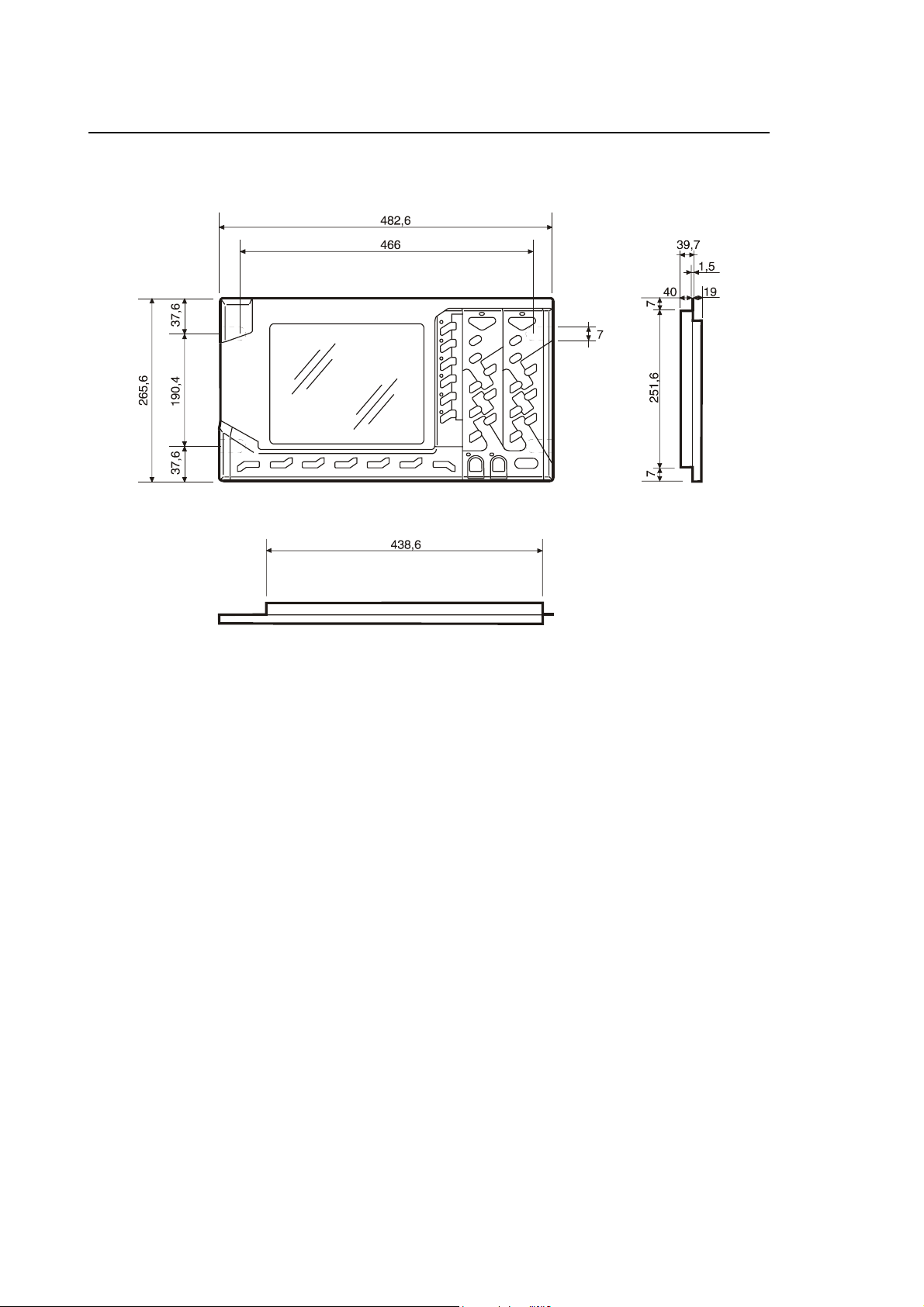
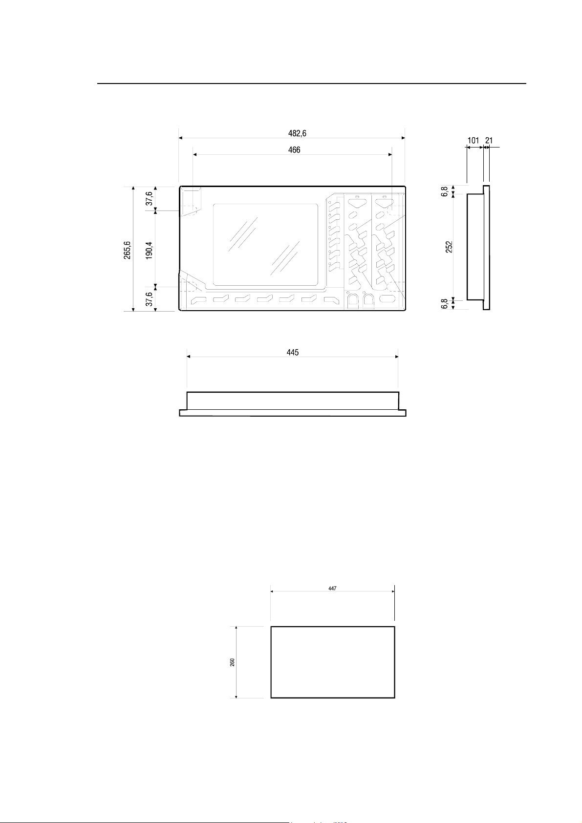
OPLINK 10.4” TFT OPERATOR PANEL
Side, front and upper view
Physical Characteristics
Width 482.6 mm
Height 265.6 mm
Depth 39.7 mm (without cables)
Weight 3.5 Kg
Mounting Rack 19"
Protection IP54
1-2 10 Series Family - Installation Guide (14)
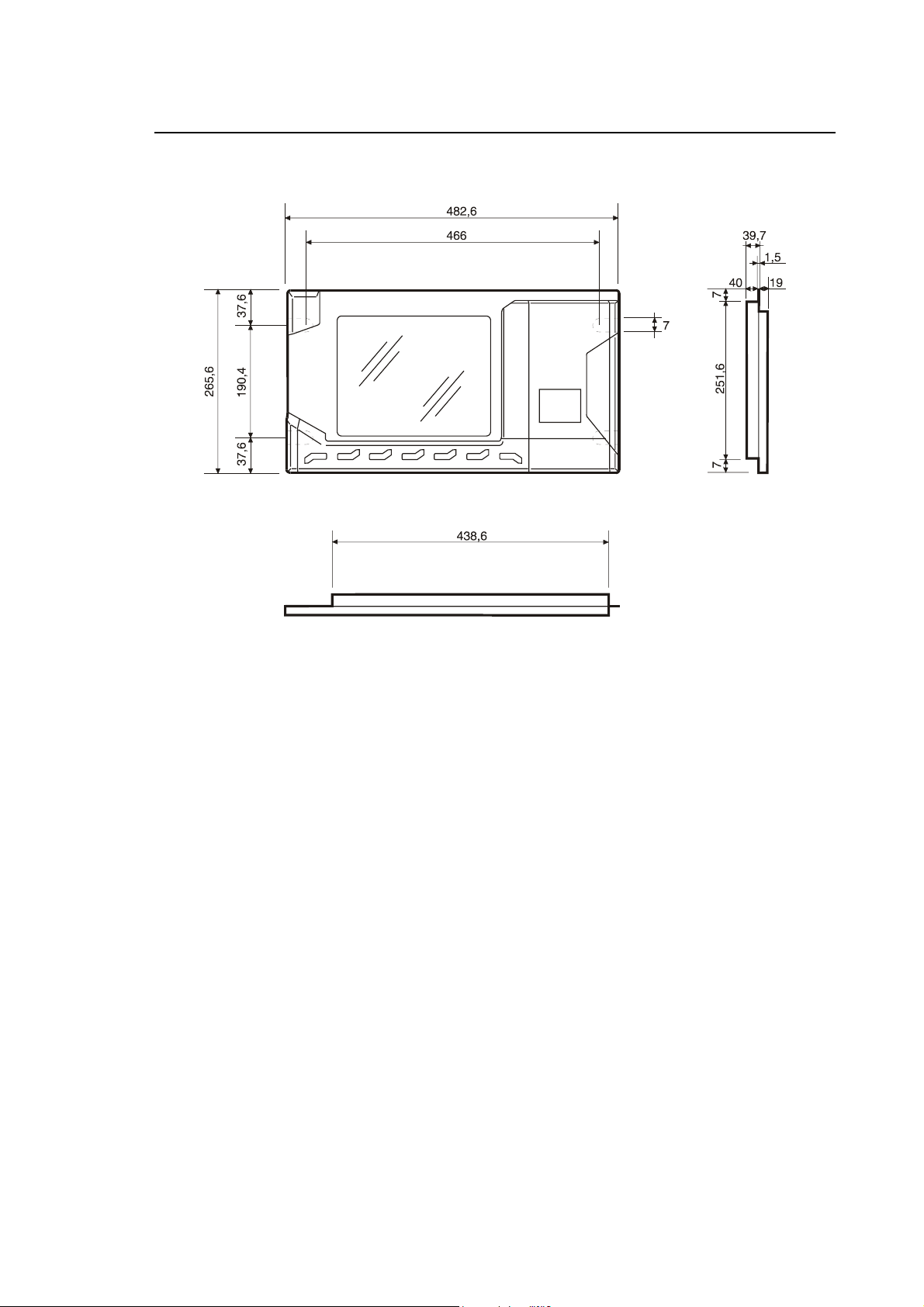
BLINK 10.4” TFT OPERATOR PANEL
Chapter 1
Mechanical Characteristics
Side, front and upper view
Physical Characteristics
Width 482.6 mm
Height 265.6 mm
Depth 39.7 mm (without cables)
Weight 3.3 Kg
Mounting Rack 19"
Protection IP54
10 Series Family Installation Guide (14) 1-3
Chapter 1
Mechanical Characteristics
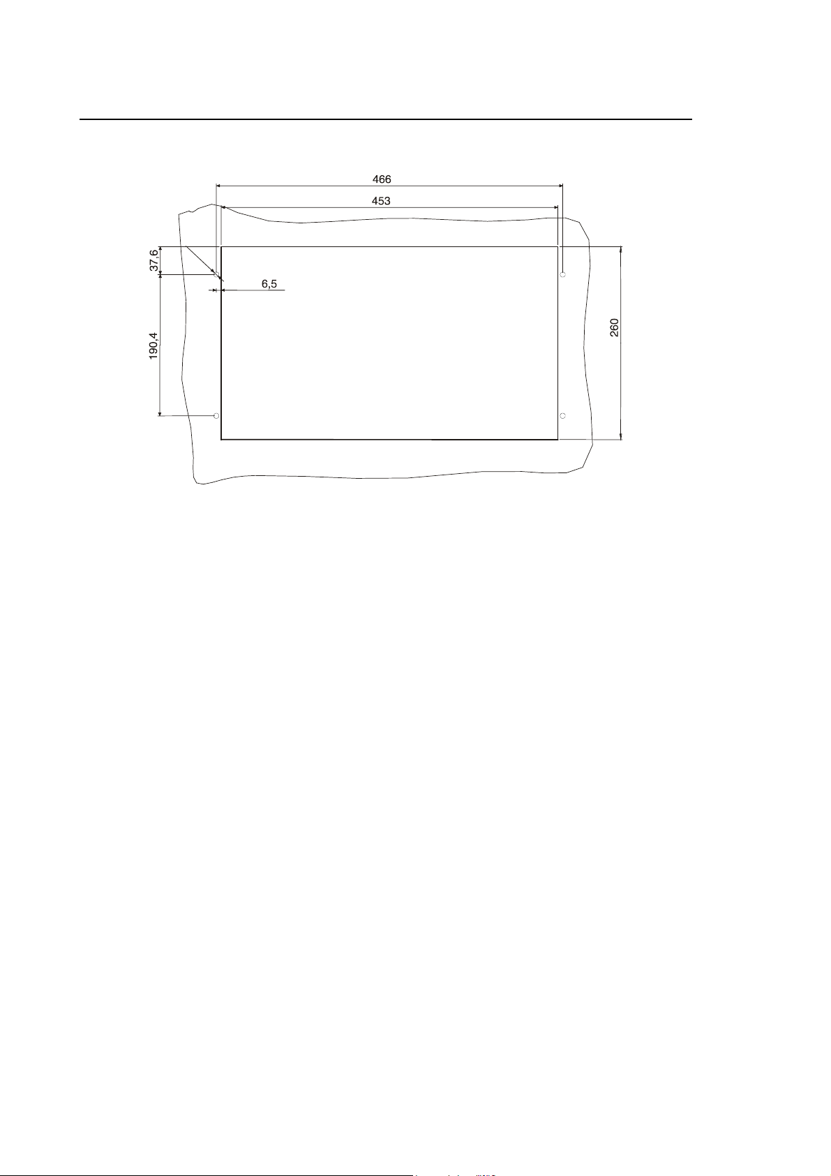
Drilling Template for OPLINK, BLINK operator panel
Ø
7
1-4 10 Series Family - Installation Guide (14)
Chapter 1
Mechanical Characteristics
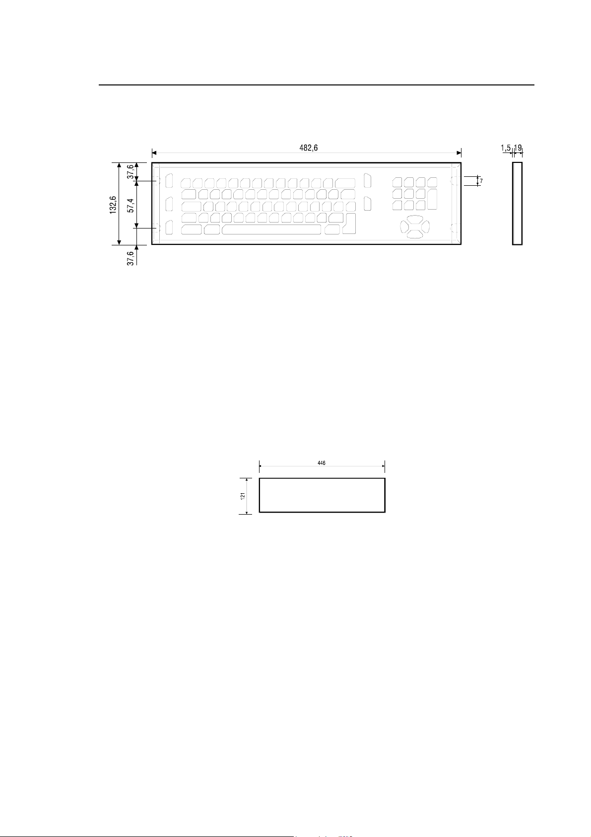
KEYBOARD FOR OPLINK, BLINK OPERATOR PANEL AND THE CONTROL UNIT 10/110
Side and front view
Physical Characteristics
Width 482.6 mm
Height 132.6 mm
Depth 20.5 mm (without cables)
Weight 1.3 Kg
Mounting Rack 19"
Drilling template for keyboard
10 Series Family Installation Guide (14) 1-5
Chapter 1
Mechanical Characteristics
FDU KIT
Two FDU kits are available for mounting on the system: Standard and Reduced. The reduced FDU
kit does not include either the FDU aluminium plate with related door and the COM1 serial interface
extension cable.
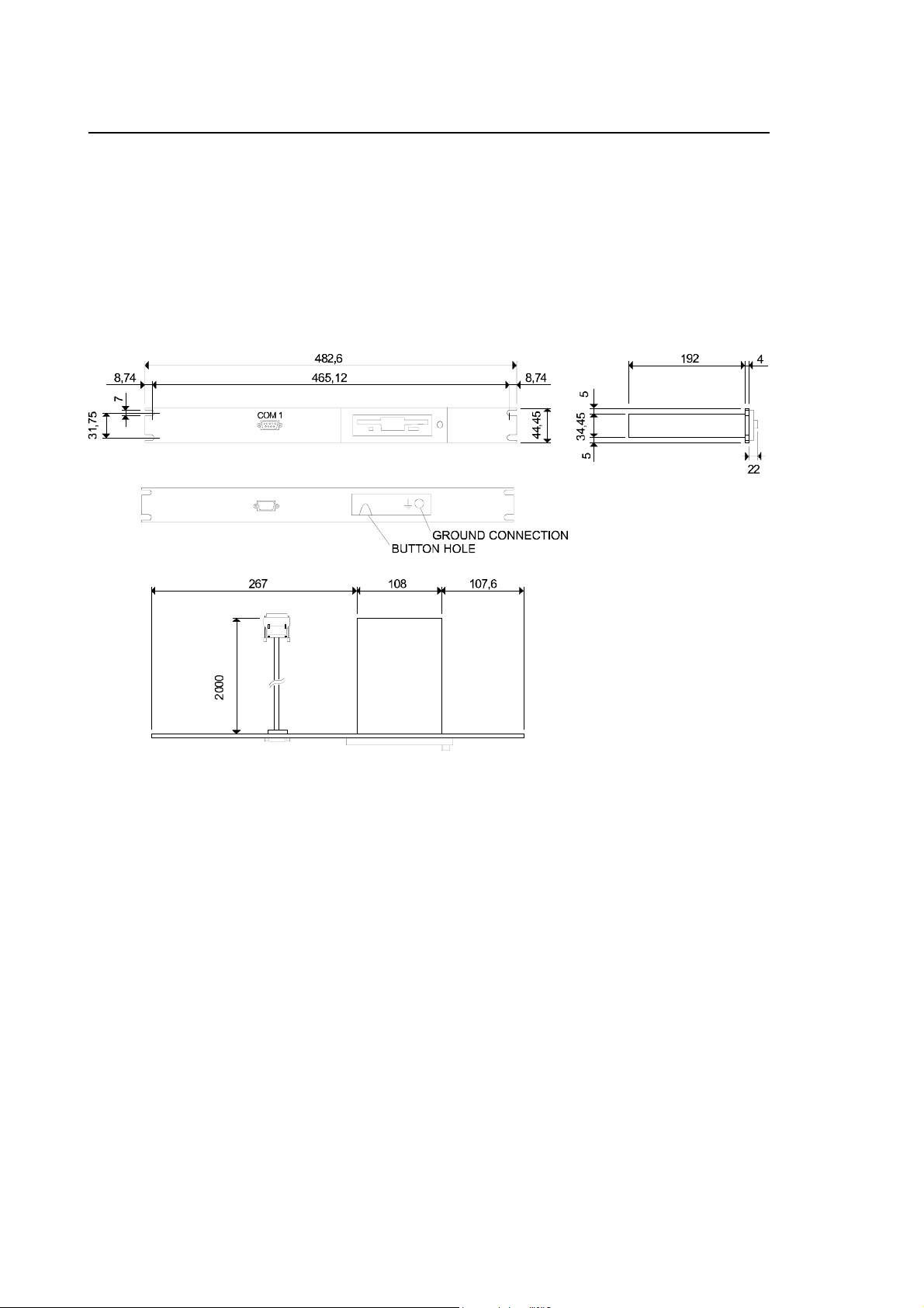
Normal FDU Kit
Front, side and upper view of the Standard FDU kit
Physical characteristics
Width 482.6 mm
Height 43.7 mm
Depth 218 mm (without cables)
Weight 1 kg
Mounting 19" rack
Protection FDU front plate
1-6 10 Series Family - Installation Guide (14)
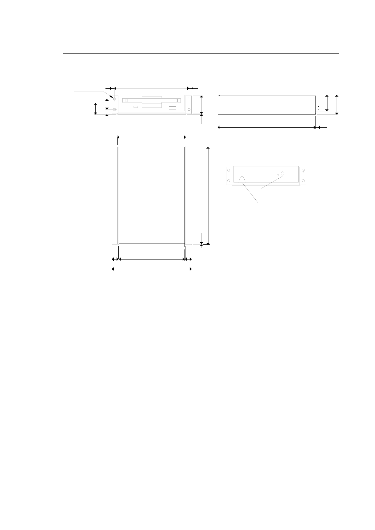
Reduced FDU Kit
Chapter 1
Mechanical Characteristics
4 Ø 4 HOLES
Floppy disk axis
17
11444
16
7,5
104,6
101,6 9,99,9
122
1,2 27,81,2
192
151 4
GROUND CONNECTION
BUTTONHOLE
25,4
30,2
Front, side and upper view of the reduced FDU kit
Physical characteristics
Width 122 mm
Height 30,2 mm
Depth 192 mm (without cables)
Weight 0,7 kg
10 Series Family Installation Guide (14) 1-7
Chapter 1
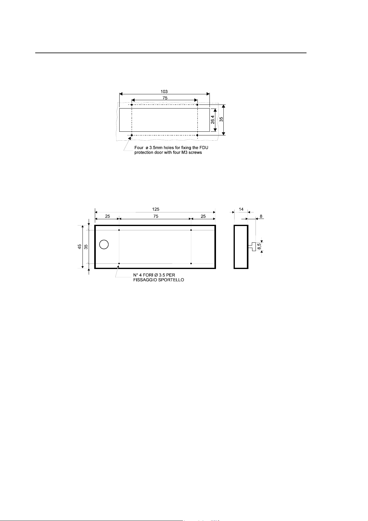
Mechanical Characteristics
Drilling template for FDU access and fixing and the corresponding
protection door
Dimensions of the protection door
1-8 10 Series Family - Installation Guide (14)
10/110 CONTROL UNIT
Chapter 1
Mechanical Characteristics
Physical characteristics
Width 482.6 mm
Height 265.6 mm
Depth 122 mm (without cables)
Weight 5,5 kg
Mounting 19" rack
Protection IP54 (front only)
Drilling Template for 10/110 Control Unit
10 Series Family Installation Guide (14) 1-9
Chapter 1
Mechanical Characteristics
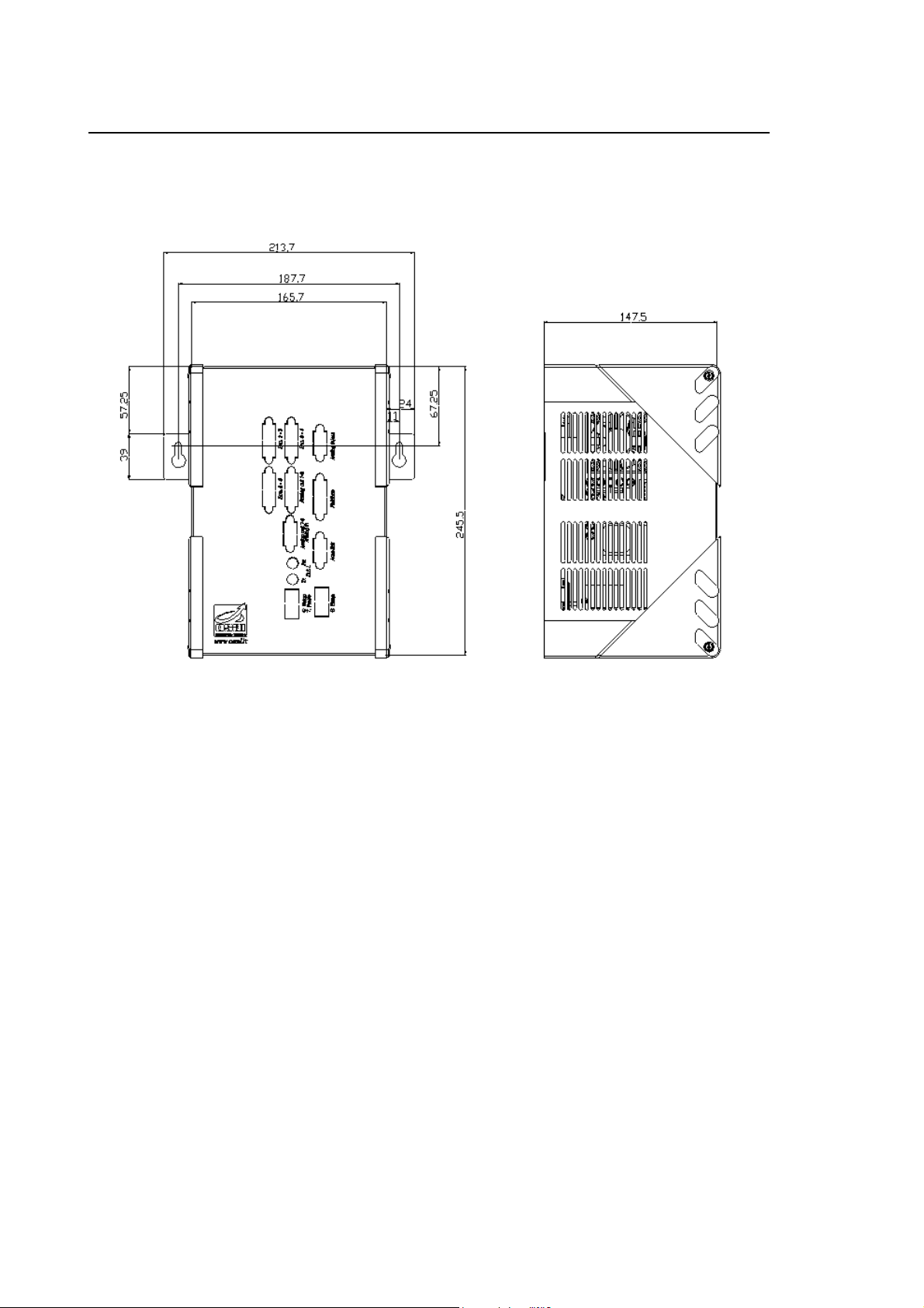
10/510S/I LIGHT CONTROL UNIT
10/510S/i Light System
1-10 10 Series Family - Installation Guide (14)
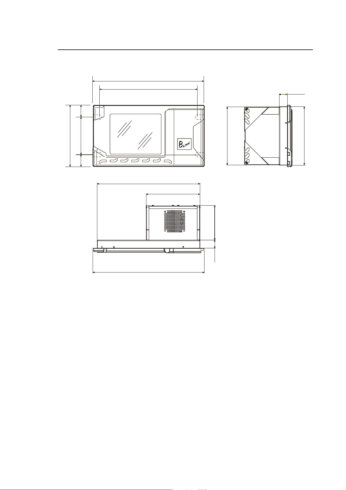
10/510i BLINK CONTROL UNIT
265
482,6
466
37,6
Chapter 1
Mechanical Characteristics
35,3
,6
190,437,6
Physical Characteristics
445
233
482,6
10/510i Blink System
249,5
150
35,3
252
Width 482.6 mm
Height 265.6 mm
Depth 290 mm (exit cables included)
Weight 6.4 Kg (boards included)
Mounting in 19” rack
Protection IP54 (only front)
Voltage 24Vdc (20÷30V)
Current 3A max (24Vdc)
10 Series Family Installation Guide (14) 1-11
Chapter 1
Mechanical Characteristics
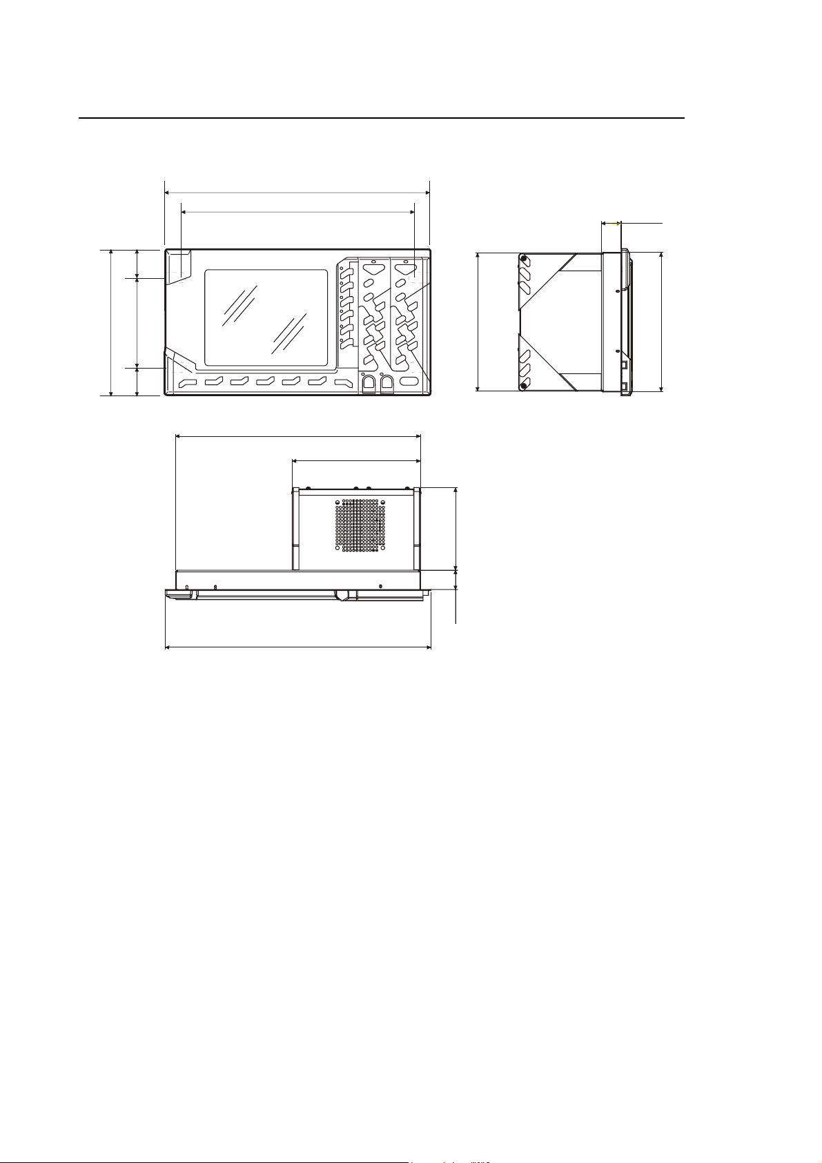
10/510i OPLINK CONTROL UNIT
482,6
466
37,6
35,3
265,6
190,437,6
Physical Characteristics
Width 482.6 mm
445
233
482,6
10/510i OpLink system
150
35,3
249,5
252
Height 265.6 mm
Depth 290 mm (exit cables included)
Weight 6.4 Kg (board included)
Mounting in 19” rack
Protection IP54 (only front)
Voltage 24Vdc (20÷30V)
Current 3A max (24Vdc)
1-12 10 Series Family - Installation Guide (14)
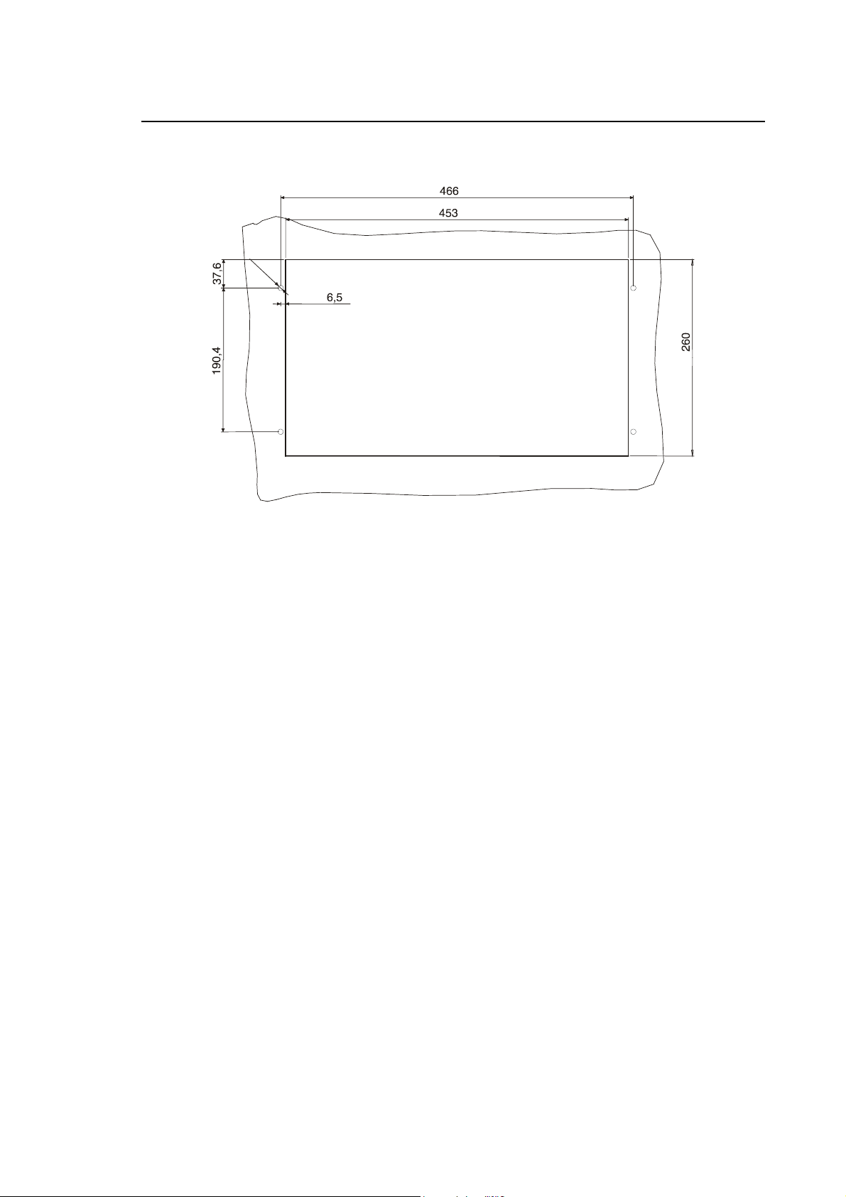
Drilling template for 10/510i Oplink/Blink Control Unit
Ø
7
Chapter 1
Mechanical Characteristics
10 Series Family Installation Guide (14) 1-13

Chapter 1
235
159
Mechanical Characteristics
10/510i CONTROL UNIT
159
27,02
257,1
233
9
235
10/510i system
Physical Characteristics
Width 235 mm
Height 311,14 mm
Depth 259 mm (exit cables included)
9
27,02
Weight 6 Kg (board included)
Mounting Mounting Bracket
Voltage 24Vdc (20÷30V)
Current 3A max (24Vdc)
1-14 10 Series Family - Installation Guide (14)

Mounting Bracket for unit 10/510i
Chapter 1
Mechanical Characteristics
Mounting Bracket for 10/510i
10 Series Family Installation Guide (14) 1-15

Chapter 1
265,6
Mechanical Characteristics
10/510I WINLINK USB CONTROL UNIT
482,6
466
37,6
190,437,6
444
7
249
150 35,3
15035,3
252
482,6
10/510i WinLink system
Physical Characteristics
Width 482.6 mm
Height 265.6 mm
Depth 290 mm (exit cables included)
Weight 10,1 Kg (board included)
Mounting in 19” rack
Protection IP54 (only front)
Voltage 24Vdc (20÷30V)
Current 6A max (24Vdc)
1-16 10 Series Family - Installation Guide (14)

Drilling template for 10/510i WINLINK USB Control Unit
Ø
7
Chapter 1
Mechanical Characteristics
10 Series Family Installation Guide (14) 1-17

Chapter 1
Mechanical Characteristics
INSTRUCTIONS FOR MOUNTING THE CONTROL UNIT TO THE PANEL
The control unit must be mounted in an enclosure providing protection against dust, oil and other
environmental agents.
This module must not be cooled with incoming external air.
IMPORTANT
If the control unit is installed in the same electrical cabinet as the power groups it is advisable to
insulate it by mounting a metal sheet or to allow at least 30 cm between the base unit and devices
such as drives, transformers or power generators. This permits to minimise electrical noise.
Since both the spindle and the axes drives dissipate a lot of heat it is recommended to mount them
above the unit.
To reduce shut down times and cost the control unit must be easily accessible to maintenance
technicians and facilitate troubleshooting.
Allow at least 10 cm around the module to ensure proper ventilation. In addition,
allow at least 20 cm between the module and the upper side of enclosure to
accommodate the board connectors and cables. Connector screws must be
tightened with a screwdriver.
INSTALLATION INFORMATION
Proper installation may be crucial to correct system operation. Please read the following guidelines
before planning the system layout:
• check that the wire channels do not exceed the allowed lengths for connections between
components.
• allow good ventilation or cooling of the electric cabin. This topic is discussed in the following
section.
• distribute the system components so that the operator enjoys a good view of both the
machining process and the front control panel. The operator must be located in a point that
facilitates access to the system controls and push buttons.
• make sure that the cabinet doors can fully open. These doors must be always closed except
during maintenance operations.
• mount the control in the enclosure allowing easy access to connectors and other components.
1-18 10 Series Family - Installation Guide (14)

Chapter 1
Mechanical Characteristics
COOLING
Cooling requirements
Like all electronic components, 10 Series modules dissipate power in the form of heat.
This means that they must be cooled on a permanent basis to prevent overheating.
Proper cooling must be ensured by forcing air circulation inside the electric cabinet in which the
unit has been installed.
If the air contains dirt and dust, these could build up on the board inside the
systems and lead to defects due to reduced insulation.
CAUTION
Therefore the cabinet should be tight. In this case air conditioning or a heat
exchanger have to be installed in order to maintain the temperature within the
specified range.
The temperature inside the cabinet with the controller must never exceed the values indicated in
the following tables:
Environment Specifications
CONTROL UNIT AND OPERATOR PANEL
Operating temperature
Storage temperature
Humidity (without condensation)
Humidity (without condensation)
Because reliability of electronic components increases at low temperatures, keeping temperatures
below the specified values permit to obtain greater MTBF (mean time between failures) values.
+5 ÷ +47 °C
-25 ÷ +60 °C
10 ÷ 90 %
20 ÷ 80% for FDU kit
10 Series Family Installation Guide (14) 1-19

Chapter 1
Mechanical Characteristics
Heat exchanger or air-conditioner
When the airflow inside the electric cabinet does not permit an appropriate heat exchange with the
cabinet walls it is necessary to install a heat exchanger or an air-conditioner.
To size the heat exchanger or the air-conditioner you need to calculate the total energy dissipated
inside the cabin. This energy is the sum of the energy dissipated by each of the devices installed in
the cabin.
If the energy dissipated by a device is unknown, total dissipated energy can nevertheless be
calculated from other known values.
Example:
to calculate the energy dissipated by an axes-drive system (transformer plus drive) dissipated
when the motor power is 1000 W you may assume the following:
Transformer efficiency = 0.95
Drive efficiency = 0.85
Average system efficiency = (0.95 x 0.85) = 0.8
Input power =
Input power =
Dissipated power = input power - motor power
Dissipated power = 1250 - 1000 = 250 W
motor power
system efficiency
1000
= 1250 W
0,8
1-20 10 Series Family - Installation Guide (14)

Chapter 1
Mechanical Characteristics
Heat exchanger
The heat exchanger cools the cabinet by forcing ventilation between. Internal air flows around the
heat exchanger, whose shape maximises the contact surface, whereas forced external air
circulates on the other side of the wall. The gradient of the heat exchanger is the ratio between the
dissipated energy and the variation of temperature.
For example, if the energy dissipated by the heat exchanger dissipates is 1000 W and the
difference of between external and internal temperature remains 11 °C, the gradient of the heat
exchanger will be:
1000W
However, since heat is also exchanged through the other walls, the internal cabinet temperature
depends on the dissipated power, the cabinet vertical surface (top and bottom excluded) and on
the heat exchanger gradient.
To calculate the difference between internal and external temperature you can use this formula:
∆t =
where:
∆t = difference of temperature in °C
Q = dissipated power in W
A = vertical surface in m
R = heat exchanger gradient in W/°C
For example:
Dissipated power: 2000W
Vertical surface: 21 m
Heat exchanger gradient: 90 W/°C
11°C
5.68A+R
= 90 W/°C
Q
²
²
∆t =
10 Series Family Installation Guide (14) 1-21
2000
[(5.68 x 21) + 90]
= 9.5°C

Chapter 1
Mechanical Characteristics
Air conditioner
Air conditioners provide continuous cooling through a refrigeration system.
The difference of temperature is given by the energy to be dissipated, the vertical surface and the
air conditioner power.
To calculate the approximate difference in temperature use these formulas:
if Q > PC + ∆t =
if Q < PC - ∆t =
where:
∆t = difference of temperature in C
Q = dissipated power in W
PC = air conditioner power in W
A = vertical surface in m
Example:
To dissipate 2000 W with a 1000 W air conditioner in a cabinet whose vertical surface is 15 m²,
use this formula:
+ ∆t =
IMPORTANT
To help assure adequate external airflow, do not mount any obstructions within 60
cm of the intake and exhaust ports of any heat exchanger or air conditioner.
Q - PC
5.68 A
Q - PC
7.37 A
²
2000-1000
5.68 A
= 11.7 °C
FIRE PROTECTION
Fire enclosures
The electric cabinet must act as a “FIRE ENCLOSURE”, in order to protect external environmental
against fire due to fault conditions of enclosed parts.
1-22 10 Series Family - Installation Guide (14)

Chapter 1
Mechanical Characteristics
VIBRATIONS, SHOCK
The OSAI Modules described in this manual will work correctly (in operating state) and not be
damaged (when not in operating state, stored or in transport) under the following vibration
conditions on the three axes:
Working conditions
Vibrations
10-57 Hz 0.15 mm peak-peak
57-200 Hz 1.00 g
Shock
15 g peak 11 msec (semisinusoidal pulse)
Non Working conditions
10-57 Hz 0.38 mm peak-peak
57-200 Hz 2.50 g
Transport and Storage
Shock
60 g peak 11 msec (semisinusoidal pulse)
10 Series Family Installation Guide (14) 1-23

Chapter 1
Mechanical Characteristics
END OF CHAPTER
1-24 10 Series Family - Installation Guide (14)

Chapter 2
ELECTRICAL CONNECTIONS
Before connecting the system to the mains check its power supply requirements, which are listed
in the tables below:
UNIT POWER SUPPLY SPECIFICATIONS
BLink and OPLink Operator Panel
No external power supply. This is provided by the connection cables from the Control Unit.
Voltage
Max. input current
12 Vdc
0.8 A (Average power draw: 8 W)
WINMEDIA ETX
Voltage:
Current:
24 Vdc ± 20%
2.5 A @ 24 Vdc
Analog/OS-Wire 10/110 control units
Voltage:
Current:
24 Vdc NOM (18 ÷ 30 V)
2.2 A at 24 Vdc (Average power draw: 40 W)
10 Series Family - Installation Guide (15) 2-1

Chapter 2
Electrical Connections
10/510S/i Light and 10/510i control units
Voltage
Current
24 Vdc, rated (20 to 30 V)
2.2 A max at 24 Vdc (Average power draw: 40 W)
10/510i OpLink-Blink Control Unit
Voltage:
Current:
24 Vdc NOM (20 ÷ 30 V)
3 A max at 24 Vdc (Average power draw: 60 W)
10/510i WinLink USB Control Unit
Voltage:
Current:
24 Vdc NOM (20 ÷ 30 V)
6 A max at 24 Vdc (Average power draw: 110 W)
2-2 10 Series Family - Installation Guide (15)

UNIT POWER SUPPLY CONNECTION AND PROTECTION GND
Analog/OS-Wire 10/110 control unit
The 10/110 Control Unit requires power of 24 Vdc nominal.
The power terminals are on the back of the Unit as shown in the following figure:
FDU
Chapter 2
Electrical Connections
Analog out 5
R
R
W
W
P
P
.
t
d
u
o
p
e
o
O
M
C
D
V
4
2
b
t
o
s
C
r
E
P
D
.
.
D
V
G
T
N
G
4
2
Enc. 4
11
Module power supply
Out section power supply 24V
Analog 10/110, detailed view of power supply connector
TX RX
Com 2 Port
Com 1 Port
Ethernet
t
l
u
a
F
Input 25-48 Input 1-24 Output 1-24
Enc. 2
Enc. 1
Analog out 1-4
Analog in Enc. 3
Keyboard
10 Series Family - Installation Guide (15) 2-3

Chapter 2
Electrical Connections
R
R
W
W
P
P
.
t
d
u
o
p
e
o
O
M
C
D
V
4
2
b
t
o
s
C
r
E
P
D
.
.
D
V
T
G
N
4
2
G
Led rosso
Red LED
FDU
Com 2 Port
Com 1 Port
Ethernet
11
Analog in Input 25-48 Input 1-24 Output 1-24
Keyboard
Led verde
Green LED
OS-Wire
Module power supply
Out section power supply 24V
OS-Wire 10/110, detailed view of power supply connector
The power has to be connected with an AWG16 having a cross section of 1.3 mm², stripping of 8
mm and using the terminal boards supplied with the module. In addition, the module case has to be
connected to ground (using an M6 screw as shown in the figure; see the “Grounding and Noise
Suppression” chapter).
NOTE
The units are protected against inversion of polarity.
2-4 10 Series Family - Installation Guide (15)

The 10/110 Control Unit is protected by a 125 V, 5 A subminiature fuse.
This is located on the motherboard in the position shown in the following figure.
For accessing it you have to open the Unit's housing. Operation not allowed !
Chapter 2
Electrical Connections
OS-Wire 10/110 Fuse Analog 10/110
Fuse location on the main board
10 Series Family - Installation Guide (15) 2-5

Chapter 2
Electrical Connections
10/510 Series Control Unit
The Units in Series 10/510, consisting of a single module and two modules, have to be supplied
with direct current of nominally 24 Vdc. The power supply terminals of each module are in the
lower part of the unit as shown in the following figures.
10/510S/i Light Control Unit
24Vdc
Ground bolt
10/510S/i Light Unit power supply
2-6 10 Series Family - Installation Guide (15)

10/510i Control Unit
Chapter 2
Electrical Connections
+24 Vdc GND
10/510i Unit power supply
GROUND BOLT
5.08 PITCH CONN.
10 Series Family - Installation Guide (15) 2-7

Chapter 2
Electrical Connections
10/510i OpLink/Blink Control Unit
GROUND BOLT
5.08 PITCH CONN.
+24 Vdc
GND
10/510i OpLink/BLink Unit power supply
2-8 10 Series Family - Installation Guide (15)

10/510i WinLinK USB control Unit
Chapter 2
Electrical Connections
GROUND BOLT
+ 24Vdc
+ 24Vdc
5.08 PITCH CONN.
10/510i WinLink USB Unit power supply
5.08 PITCH CONN.
GROUND BOLT
10 Series Family - Installation Guide (15) 2-9

Chapter 2
Electrical Connections
NOTE:
For the power supply connection use an AWG16 wire with a cross section of 1.3 mm² having
removed the isolation for 8 mm and the terminal board supplied with the module.
Connect the grounding bolt (M4 screw) of the module of the chassis with ground (only one rack for
the WinLink unit) as shown in the figure. Check the "Ground Connection and Noise" Chapter.
Each rack is protected against pole inversion and has a subminiature fuse (125V 5A) on the 24
Vdc supply line.
If is fitted to a base on the back board as shown in the following figure.
To access it you have to open the unit's back panel (OPERATION NOT PERMITTED!).
Another resettable type fuse protects the FDU external peripheral, if fitted.
EXTERNAL FDU FUSE
PWR IN FUSE
J19
1 2
+ -
BOARD POWER SUPPLY
Fuse locations on OS8502 Back Board
(10/510i, 10/510i OpLink/BLink, 10510i WinLink USB)
2-10 10 Series Family - Installation Guide (15)

Electrical Connections
POWER
ALIMENTATORE
SUPPLY UNIT
+5V @ 10 A
+12V @ 2 A
-12V @ 250 mA
-5V @ 30 mA
Chapter 2
EXTERNAL FDU FUSE
BOARD POWER SUPPLY
Identification of fuses on OS8505 Back Board
(10/510S/i Light)
PWR IN FUSE
J8
12
24V
+
ALIM. PIASTRA
-
10 Series Family - Installation Guide (15) 2-11

Chapter 2
Electrical Connections
General interconnection diagram
OPERATOR PANEL
Power connections to Series 10/510 modules in their various versions
NOTE:
The operator panel is not present in versions 10/510S/i Light and 10/510i. In the case of unit
10/510i WinLink USB two modules have to be powered.
END OF CHAPTER
2-12 10 Series Family - Installation Guide (15)

Chapter 3
GROUNDING AND NOISE SUPPRESSION
All the devices connected to a machine tool controlled by a 10 SERIES system must be properly
grounded in order to guard against electric shock to people who touch them. Grounding also helps
reduce the effect of electromagnetic noise.
All earth grounding connections must be continuous and permanent. A grounding connection must
not be interrupted by a switch.
The connections of grounding wires must comply with Article 13 of the IEC 204-1 code.
IMPORTANT
Use copper conductors for all connections to ground. If conductors are isolated,
insulation can be yellow or green.
EARTH GROUNDING
Each subset installed in the electrical cabinet must have its own connection to ground. In other
words, the grounding terminal strip of each subset must be connected separately to the cabinet's
ground bus bar. Keep the wires used for this connection as short as possible.
If a subset needs a connection to earth for the AC power supply terminal strip, this point must be
also connected to the cabinet's ground bus bar.
If the system is made up of various cabinets, the bus bar of each cabinet must be connected to the
bus bar of the main power cabinet, which is in turn connected to the earth ground system of the
plant.
10 Series Family - Installation Guide (06) 3-1

Chapter 3
Grounding and Noise Suppression
Cabinet earth grounding
Each cabinet must be connected to its bus bar through any stud or bolt bonded to the structure of
the cabinet.
Carefully remove all paint or insulating material from the contact area. Use a ring terminal at the
end of each conductor.
Grounding connection scheme
3-2 10 Series Family - Installation Guide (06)

Chapter 3
Grounding and Noise Suppression
ELECTRICAL NOISE
General information
Electrical noise is any unwanted electrical signal.
Electrical devices to which voltage is applied are typical noise sources. Electrical noise is
characterised by its frequency, waveform and intensity.
Here are the main three types of electrical noise:
1 electrostatic noise:
this type of noise is produced by an alteration of the electrical field that is transferred to the
circuit by a capacitive action;
2 magnetic noise:
is produced by an alteration of the magnetic field that is transferred to the circuit by an inductive
action;
3 electromagnetic noise:
is a combination of electrical and magnetic noises.
Noise sources
One of the main sources of electrical noise is the rapid variation of current in an inductive circuit.
The maximum exchange of current occurs when the circuit opens.
An overcurrent peak generates a sudden increase of voltage in the opening contact of the circuit.
10 Series Family - Installation Guide (06) 3-3

Chapter 3
Grounding and Noise Suppression
Noise suppression
The overvoltage generated by opening an inductive circuit must be suppressed by installing a
suppressor next to the overvoltage generator, as shown in the figure below:
+ V
100
Ω
Load
0,5µF
Installing a noise suppressor
3-4 10 Series Family - Installation Guide (06)

Chapter 3
Grounding and Noise Suppression
Suppressing DC noise in c.c.
The characteristics of this suppressor are:
Diode = 1 A 800 V reverse
Resistor = 100 Ohm
Condenser = 0.8 µF
Max. voltage = 400 V
Allen-Bradley can supply you with a pre-assembled group (code 5091137 F) whose physical
characteristics are shown in the figure below:
DC Noise suppressor
10 Series Family - Installation Guide (06) 3-5

Chapter 3
Grounding and Noise Suppression
Suppressing AC noise
The typical AC noise suppressor is a Resistor-Condenser group (R-C group) whose characteristics
are as follows:
R = 100 Ohm
C = 0.5 µF
Max. voltage = 400 V
The commercial code of this group is 5091135 X.
The schematics and size of this suppressor is shown in the figure below:
AC noise suppressor
3-6 10 Series Family - Installation Guide (06)

Chapter 3
Grounding and Noise Suppression
Noise suppression in AC motors
In AC motors the noise suppressor is an RC group installed between phases as shown in the
figure below.
This three-phase group is made up of resistors and condensers with the following characteristics:
R = 22 Ohm
C = 0.22 µF
Max. voltage = 500 V
The code of this pre-assembled RC group is 9327045 X.
3-phase
motor
s
w
e
r
c
s
6
M
3M6
3
SCREWS
1-phase
3-phase noise suppressor for AC motors
motor
10 Series Family - Installation Guide (06) 3-7

Chapter 3
R
Grounding and Noise Suppression
Connections to earth
A correct grounding helps reducing noises: for this reason must be implemented carefully
according to the following points:
• Connect all the application units to earth.
• Do not connect multiple electronic chassis in series to ground. Connect each separate bus to
the main ground.
• Connect the GND of the AC line to the control chassis. Returns should be grounded only
through the control chassis.
Figures 3.6 and 3.7 provide examples of correct and incorrect electric connections of a machine
tool.
R
S
T
Num erical
Control
El e c t r ic
Cabinet
NC Ma c hine Tool
Example of correct connection
Machine
To o l
Conventional
Machine
Tool
S
T
Conventional
Machine
To o l
3-8 10 Series Family - Installation Guide (06)

Chapter 3
Grounding and Noise Suppression
R
S
T
Machine
Tool
Electrical
Cabinet
NC Machine Tool
Example of incorrect connection
Numerical
Control
Conventional
Machine
Tool
R
S
T
Conventional
Machine
Tool
CROSS-SECTIONAL AREA OF PROTECTION CONDUCTORS
The protection conductor between the module in question and the earth busbar must offer
resistance of less than 0.1 Ohm.
Use of the following cables is recommended for cross-sectional area requirements:
AWG14 for lengths of up to 3 metres
AWG12 for lengths of between 3 and 15 metres
AWG10 for lengths of between 15 and 25 metres
10 Series Family - Installation Guide (06) 3-9

Chapter 3
Grounding and Noise Suppression
Shielded cables
To block electrostatic coupling use shielded cable as required in the manual.
In the figure below check the following:
• Whenever you have to break a shield at a terminal strip or a connector, keep exposed signal
wires as short as possible and use a terminal strip or a connector to give continuity to the
shield.
• Use shielded twisted pairs, especially for connecting analog or low level signals.
Do not ground the shield
at cabinet end and
insula te all exp osed
leng ths
NUMERIC AL
CONTROL
CAUTION
CABINET
Non-shielded co nducto rs
must be kept at
minimum length
Shielded cable use
To guard against damage to the machine, never use the shield as a
common, ground or return wire. If a shield is not used exclusively as a shield,
the resultant noise can cause unexpected machine tool action.
3-10 10 Series Family - Installation Guide (06)

Chapter 3
A
A
A
U
l
A
Grounding and Noise Suppression
Cable routing
To optimise machine wiring, check the following (refer to Figure below):
• Voltage and/or current low and high power level signals must be routed separately to opposite
sides of the cabinet.
• In wireways wires must be bundled according to similar power levels and functions.
• Do not install critical low level signal cables close to high energy cables.
• Install steel sheet metal wireways between machine application cabinets. Do not use aluminium
or other non-ferrous wireways. Do not use dissimilar metals.
• If possible use separate wireways for cables of different voltage and power levels.
C line and Digital I/O
Po w e r
distribution
Po w e r
In p u t
panel
Use m eta l
sh e e t a s se p a ra t o r
10/ Se rie s C NC
Po w e r
distribution
panel
Wireways
xe s sig n a ls
Feedback
Drive po wer
nalog signals
Installing signal wireways
Cabinets
Cabinets accommodating electronic devices must be built in steel sheet.
Avoid putting viewing windows or openings.
xe s d riv e
se m eta
sheet as
se p a r a t o r
Avoid mounting high energy sources close to sensitive devices. Use a metal barrier if necessary.
10 Series Family - Installation Guide (06) 3-11

Chapter 3
Grounding and Noise Suppression
END OF CHAPTER
3-12 10 Series Family - Installation Guide (06)

Chapter 4
EMERGENCY CIRCUIT
In order to avoid injuries to people and damages to the machine, its emergency circuit also has to
be enabled from the Controller side. This makes the contacts of its emergency relay available on
the pins of the CUSTOMER CONNECTOR sits:
• on the back of the 10/110 Control Unit;
• on the back panel of the 10/510i OpLink, 10/510i BLink and 10/510i WinLink USB Control Units
(CN module).
WARNING
When the emergency circuit is activated, all axis and spindle drives must be
disabled. Otherwise, uncontrolled axis motion can cause injury to personnel or
damage to the machine tool.
10 Series Family - Installation Guide (16) 4-1

Chapter 4
Emergency Circuit
EMERGENCY CONNECTIONS FOR MONO-PROCESS SYSTEMS
The following figures provide examples of correct connection of the emergency circuit on 10/110,
10/510i, 10/510i WinLink USB mono-process unit.
CUSTOMER CONNECTOR
Emergency circuit for 10/110, 10/510i, 10/510i WinLink USB units
It is possible to see that the emergency circuit starts from the 110 VCA or 24 VDC auxiliary phase
and is series-connected with:
• the contact normally open of a relay controlled by the system diagnostic software (SPEPN
signal) available on the CUSTOMER CONNECTOR.
• the ON push-button, which is connected in parallel to the contacts of the auxiliary relay.
• the Emergency push-button(s) defined during installation, whose contacts open when an
emergency is generated by pressing the push-button.
• the axes software travel limit switches whose contacts open when an axis travels over the
switch.
• a contact connected to various system devices (thermal magnets, thermal sensors, etc.), which
opens when a malfunctioning of these devices occurs.
• The emergency terminates on the auxiliary relay coil. The opposite side of the coil connects to
the 110 V AC neutral line or the 24 V DC common line.
The auxiliary relay can be activated only if all the contacts in the string are closed.
NOTE:
• All the Emergency push-buttons must respect the EN418 standards, i.e. be of "positive
mechanical opening".
• To avoid the adherence of the contacts if the machine overheats (normal current 10 A
contacts), it is recommended that a fuse emergency circuit be incorporated, (See diagram
"Emergency Circuit" in this chapter).
• Pressing the Emergency push-button guarantee the opening of the contact in adherence
• If the Portable Console is present, for safety reasons, the emergency circuit must be wired to
the 24 VDC and not the 110 VCA.
4-2 10 Series Family - Installation Guide (16)

Chapter 4
Emergency Circuit
MANAGEMENT OF ANOMALIES ASSOCIATED WITH THE EMERGENCY
Following a serious internal failure of the control (a Watch dog, for example), the software blocks
all the system functions, in particular movement of the axes and execution of part programs; the
analogue outputs to the drives are reset and the contact of the GEN. ESTOP relay (SPEPN) is
opened.
The system enters non-recoverable emergency status, to exit from which the control must be
switched off and on again after the cause of the problem has been removed (for a fuller, more
detailed description of the non-recoverable emergencies, see the PLUS Application manual).
Following a process anomaly (a servo error, axes not in tolerance, for example), the system
software blocks some functions, in particular movement of the axes and execution of part
programs; the analogue outputs to the drives are reset.
Where necessary, the machine logic will ask the system for a recoverable emergency status, as a
result of which the contact of the GEN. ESTOP relay will be opened on mono-process units or the
contact of the relay of the process in question, PRn ESTOP, on multi-process units.
For machine device anomalies, such as circuits in alarm, drives broken, thermal switches triggered
(protections on pumps, brakes, etc.), these problems must be signalled to the system through the
digital inputs using contacts associated with the auxiliary relays.
Where necessary, the machine logic will ask the system for a recoverable emergency status, as a
result of which functions such as movement of the axes and execution of part programs will be
blocked; the analogue outputs to the drives will be reset and the contact of the GEN. ESTOP relay
will be opened on mono-process units or the contact of the relay of the process in question, PRn
ESTOP, on multi-process units.
If, in cases of process or machine device anomalies, the system logic (implemented by the user)
has requested opening of the contact of the GEN. ESTOP/PRn ESTOP relay, the logic can then
ask for it to be closed again, subject to removal of the problem, thus allowing the plant to be
switched on again with a general power-down of the system (for a fuller, more detailed description
of the recoverable emergencies cycle, see the PLUS Application manual).
To inform the system logic of general status of the emergency circuit, a normally open contact of
the auxiliary relay will be used, sent to the control through a digital input.
10 Series Family - Installation Guide (16) 4-3

Chapter 4
Emergency Circuit
END OF CHAPTER
4-4 10 Series Family - Installation Guide (16)

SYSTEM CONNECTIONS
OPLINK/BLINK OPERATOR PANEL CONNECTIONS
10/510i Control Unit
10/510i
Chapter 5
Connection between the OPLink, BLink Operator Panels and 10/510i Control Unit
10 Series Family - Installation Guide (15) 5-1

Chapter 5
System Connections
Connection Cables
The following shows the connection cables with the numbers indicated in the previous figures.
c Keyboard cable with 15-way MA/FE D-shell connectors.
d LCD signals cable with 15-way high density MA/FE D-shell connectors
NOTE:
To connect the Control Unit to the Operator Panel for a distance of max. 30m you need to use two
LCD signal cables interrupting them with an “LCD Repeater” device.
e Physical keyboard connection cable with 25-way MA/FE D-shell connectors.
MAX LENGHT 0,8m
25 PIN MALE
CONNECTOR PANEL END
25 PIN FEMALE
CONNECTOR KEYBOARD END
5-2 10 Series Family - Installation Guide (15)

NOTE:
The BLink operator panel does not use the 5 Console connection cable.
g Console cable with 9/9 FE/FE connectors for 10/510i Control Unit.
Chapter 5
System Connections
10 Series Family - Installation Guide (15) 5-3

Chapter 5
System Connections
Layout of Console Cable for 10/510i Control Unit
Use the AWG 26 shielded twisted pair cable. One twisted pair carries the RXC00 and RXC0N
signals (data transmitted by the NC and received by the panel), the other carries the TXC00 and
TXC0N signals (data transmitted by the panel and received by the NC). The connectors on the two
ends are of the same type. In order to avoid inversion, they should be labelled (e.g. “NC SIDE” ,
“PANEL SIDE”.
10/510i SIDE SHELL
CONNECTOR (9 PIN FE)
5-4 10 Series Family - Installation Guide (15)

Chapter 5
System Connections
Long distance LCD repeater connection
You can use the LCD repeater when the distance between the OPLink, BLink Operator Panels and
the Control Unit is more than 15m. With this device you can reach a maximum distance of 30m.
The electronic device comes in a metal container which should be fixed on a support with a ground
connection.
The device has two high density 15 way MA and FE D-shell connectors which are connected to the
cables: from the Control Unit to the Operator Panel.
LCD Repeater Dimensions in mm
10 Series Family - Installation Guide (15) 5-5

Chapter 5
System Connections
CONNECTING THE FDU KIT TO THE CONTROL UNIT
There are two types of FDU kits:
• Normal, with an aluminium front, FDU access bay and a COM1 serial interface extension cable.
• Reduced, without front piece and serial interface extension cable.
• Cable with cupped 37-pin connector for Series 10/110, 10/510i Units.
The following figures show the connections and the cables for the various Control Units.
Analog 10/110 Control Unit
R
R
W
W
P
P
.
t
d
u
o
p
e
o
O
M
C
D
V
4
2
b
t
o
s
C
r
E
P
D
.
.
D
V
T
G
N
4
2
G
11
FDU
Com 2 Port
Com 1 Port
Analog out 5
Enc. 4
Output 1-24
TX RX
l
u
a
F
Input 25-48 Input 1-24
Enc. 2
Enc. 1
t
2
Ethernet
Analog out 1-4
Analog in Enc. 3
Keyboard
1
Connection between FDU kit and analog 10/110 control unit
5-6 10 Series Family - Installation Guide (15)

OS-Wire 10/110 Control Unit
R
R
W
W
P
P
.
t
d
u
o
p
e
o
O
b
M
t
o
s
C
r
C
E
P
D
D
.
.
D
V
V
G
T
N
4
4
2
G
2
11
Analog in Input 25-48 Input 1-24 Output 1-24
Keyboard
Led rosso
Red LED
OS-Wire
Chapter 5
System Connections
FDU
Com 2 Port
Com 1 Port
Ethernet
Led verde
Green LED
2
1
Connection between FDU kit and OS-Wire 10/110 control unit
10 Series Family - Installation Guide (15) 5-7

Chapter 5
System Connections
10/510i, 10/510i OpLink-BLink Control Units
Parallel
Port
CO
Interbus
RS232
Interbus
Bus
M2
Po
rt
Ethernet connection
COM1
(VGA)
FDU
Keyboard
(KBD)
Tx Rx
I/O Ring
Fault
Eth.
24 Vdc Pwr in
1
2
External FDU kit connection to the 10/510i, 10/510i OpLink, 10/510i Blink.
5-8 10 Series Family - Installation Guide (15)

Chapter 5
System Connections
Connection Cables
c Floppy Unit power and signal cable with 4-pin EI and 34-pin PI type connectors and MA 37-pin
D-shell for 10/110 and 10/510i Control Units.
d COM1 serial interface extension cable (length: 2 m)
This cable must be plugged to the COM1 connector in the Control Unit.
NOTE:
The RS232 serial line cannot be more than 15 m long (extension included).
Peripheral connections are discussed in Chapter “Peripherals Units”.
The following figure illustrates the pin-out and front view of the serial interface connector. The
abridged FDU KIT does not include either a serial interface extension cable or a support brake.
Floppy Disk Unit connections remain unchanged.
PIN I/O SIGNAL 9-PIN MALE D-SHELL CONNECTOR
1
2
3
4
5
6
7
I
I
O
O
I
O
DCD
RXD
TXD
DTR
M
DSR
RTS
6
1
5
9
8
9
10 Series Family - Installation Guide (15) 5-9
I
I
CTS
RNG

Chapter 5
System Connections
INSTALLING THE PORTABLE TEACH PENDANT
The Intelligent Portable Console kit comprises the following codes:
93000552U Standardised Teach Pendant for MC-GP with 3 metre cable to COM1/2 CNC
93000553W 5 metre cable for connection to routing board
93000647B 8 metre cable for connection to routing board
93000554W 12 metre cable for connection to routing board
93000906N Specialised version for GP
93000907Q Specialised version for MC
For detailed information on the use of the console, see manuals Code: 45004486N "CNC Series
10 Intelligent Portable Console" (MC version) and code 45006771N "GP Series 10 Teach Pendant"
(GP version).
Emergency button
Man
present detector
View and dimensions of Intelligent Portable Console
5-10 10 Series Family - Installation Guide (15)

Chapter 5
Y
System Connections
Connection
The console is connected to the rest of the system (CNC, safety devices), through the OS8119
adapter board, which is fastened to the inner door of the electric cabinet via a metal support. This
board ensures:
- the connection to the console via a 12-pin connector (mounted externally to the electric cabinet)
- the connection to an RS232 serial line (COM1/COM2 ) via a 9-pin connector
- the connection to the emergency and safety circuits via an 8-pin connector
- the power supply to the console via a 2-pin connector
The console is connected by means of a cable ending in a 12-pin threaded bayonet connector
which is screwed into the mating connector in the OS8119 board.
NOTE
When the console is not present, it is necessary to plug the connector in the OS8119 board with a
dummy connector that short-circuits the wires in both emergency circuits.
CONSOLE
CONSOLE CABLE
DUMMY PLUG TO BE
FITTED WHEN THE
CONSOLE IS NOT
PRESENT
ELECTRIC CABINET
CONTROL
UNIT
COM1
OS8119
ADAPT ER
BOARD
12
PI
N
2 PIN
12
PI
N
9
PI
8
PI
N
SERIAL CABLE
EMERG. CIRCUIT 1
EMERG. CIRCUIT 2
LIVE-MAN CIRCUIT 1
LIVE-MAN CIRCUIT 2
POWER CABLE
COM2
24 VDC
POWER
SUPPL
Diagram for connecting the ITP to 10 Series systems.
10 Series Family - Installation Guide (15) 5-11

Chapter 5
System Connections
Adapter board
The adapter board is fastened with four screws onto the inner wall of the electric cabinet via a
metal support. Effective shielding of the cable linking the console to the board requires good
electric contact between the two parts: to this end, leave the areas around the four screw holes in
the inner wall of the cabinet bare (unpainted). The figures below show: the board mounted on its
metal support, a view of the assembly and the drilling template.
OS8119 adapter board
J1 2-pin Weidmuller terminal strip for 24 VDC power supply (note)
J2 9-pin female connector for connection to the serial line of the Series 10 unit.
J3 8-pin Weidmuller terminal strip for two circuits of the emergency button and two circuits of
the Live-Man button.
J4 12-pin threaded bayonet connector for connection of cable from console.
NOTE:
The OS8119 board can be powered with 14Vdc to 30Vdc voltage and max. current consumption is
100 mA.
5-12 10 Series Family - Installation Guide (15)

Chapter 5
System Connections
View of assembly mounted on electric cabinet wall
Drilling template
10 Series Family - Installation Guide (15) 5-13

Chapter 5
System Connections
Power connector J1
Pin Function
1 +24VDC
2GND
Connector for emergency and Live-Man buttons, J3
Pin Function Type of contact
1-2 Emergency circuit 1 Normally closed
3-4 Emergency circuit 2 Normally closed
5-6 Live-Man circuit 1 Normally open
7-8 Live-Man circuit 12 Normally open
All contacts can withstand 24V@0.5A max.
J4 connector for console connections
Pin Function
1-2 Live-Man circuit 1
3-4 Emergency circuit 2
5-6 Emergency circuit 1
7
8-9
10
8-12 VDC power supply
Live-Man circuit 2
RX00L ser. data to console
11
12
TX00L ser. data from console
GND
5-14 10 Series Family - Installation Guide (15)

Chapter 5
System Connections
FEMALE-MALE CONNECTORS OF SERIAL CABLE
The layout below shows the pin-out of the connectors fitted to the cable linking the NC to the
OS8119 board.
9-pin male connector to be inserted
into J2 (female) of OS8119
9-pin female connector to be
inserted into COM1/COM2
(male) of NC
Pin Signal Pin Signal
1, 4, 6, 7, 8, 9 ----------- 1 -----------
2 Tx (to NC) 3 Tx (from console)
3 RX (from NC) 2 RX (to console)
5 GND (ground) 5 GND (ground)
NOTE: cable shield must be fastened under the metal straps on both sides
9-PIN MALE, ON 0S8119 SIDE
9-PIN FEMALE, ON CU SIDE
9-pin male / 9-pin female cable connectors
10 Series Family - Installation Guide (15) 5-15

Chapter 5
System Connections
Dummy plug
The dummy plug consists of a 12-pin threaded female metal connector which is screwed in place
(INTERCONTEC p.n. ASTA 021 FR 1162 003500 or equivalent product), the same type as is fitted
to the console cable.
Contacts to be short-circuited by means of internal U-bolts: 1-2 (emergency circuit 1)
3-4 (emergency circuit 2)
5-6 (live-man circuit 1)
8-9 (live-man circuit 2)
Dummy plug
END OF CHAPTER
5-16 10 Series Family - Installation Guide (15)

Chapter 6
SERIES 10/510 UNITS
10/510S/i Light UNIT
General and views of unit 10/510S/i Light
Unit 10/510S/i LIGHT contains all the functions needed to manage digital axes and I/O environments of
different sorts. It consists of a module without front panel to be installed in an electric cabinet, it is
connected to a Front End PC via the Ethernet network.
Versions 10/510S LIGHT and 10/510i Light differ solely on account of the characteristics of the CPU
board used.
GND bolt
24Vdc
10/510S Light and 10/510i Light Control Units
10 Series Family - Installation Guide (16) 6-1

Chapter 6
Unit 10/510
Process Boards
Front panel of 10/510S Light and 10/510i Light, detailed view of board zone
6-2 10 Series Family - Installation Guide (16)

Chapter 6
Unit 10/510
View of bottom panel of Unit 10/510i Light
Note:
Version 10/510S Light differs solely for connectors “Eth” and “Com1”, whose positions are reversed.
Led
If lit, DC OK LED shows that the module is powered (bottom panel).
Back Board
Characteristics
• 24Vdc power supply (on-board power supply unit)
• 3 ISA slots (one reserved for the CPU)
• Connectors for: external Fdu power supply
CPU reset
Flash disk power supply
DC OK Led
10 Series Family - Installation Guide (16) 6-3

Chapter 6
Unit 10/510
10/510S Light Cpu Board (ProX-1260)
• 533 MHz Mark VIA Eden Cpu
• 64 Mbyte dynamic RAM
• 256K Flash EPROM (System BIOS and video BIOS)
• PC/AT compatible chip set
• CRT/FLAT PANEL VGA 640x480 and SVGA 800x600 Controller
• 2 Mbyte video memory (in the system memory)
• Floppy Disk controller
• IDE interface for HDU
• Connector for VGA SVGA CRT
• 2 serial ports: COM1 (RS 232) and COM2 (adjustable for RS232, RS422, RS485)*
• 1 SPP/ECP/EPP parallel port
• Keyboard controller with PS/2 interface and Minidin connector
• Insertion on ISA BUS
• PC-104 expansion connectors
• Ethernet connector (RJ-45)
10/510i Light Cpu Board (ProX-1635)
• 850 MHz Celeron CPU
• 128-Mbyte RAM
• 256K flash EPROM (system BIOS and video BIOS)
• PC/AT compatible chip set
• CRT/FLAT PANEL VGA 640x480 and 800x600 controller
• 2-Mbyte video memory
• Floppy disk controller
• IDE interface for HDU
• Connector for CRT VGA
• 2 serial ports: COM1 (RS 232) and COM2 (adjustable for RS232, RS422, RS485)*
• 1 SPP/ECP/EPP parallel port
• Keyboard controller with PS/2 interface and Minidin connector
• Insertion on ISA BUS
• Ethernet connector (RJ-45)
Mass memory
Mass memory consists of a Hdu, fixed internally by means of a bracket, or a Flash disk module.
NOTE*:
Serial line “COM2” cannot be configured by the user. A configuration other than RS232 (default) must
be requested when ordering by specifying the appropriate commercial code.
6-4 10 Series Family - Installation Guide (16)

Chapter 6
Unit 10/510
External connections
Com1 RS232
Com2 RS232/RS422*/RS485*
LAN (Ethernet)
Keyboard (6-pin minidin) Suitable for connecting a keyboard and a VGA/SVGA CRT, or a
Video (15-pin) TFT display (max. 5 m).
Fdu Bottom panel, in alternative to the internal panel.
Expansion boards
The module can be equipped with application-specific expansion boards. The boards used most widely
are listed below. For the characteristics of the individual boards, see the corresponding sections.
Analog and Sercos axis board (slot 2): OS8511 - OS8511/1 - OS8511/2 - OS8511/3
Sercos board (slot 2): OS8513 – OS8513/1 - (OS8512 - OS8512/1)
Mechatrolink axis board (slot 2): OS8516 – OS8516/1 – OS8516/2
Analog input board (slot 3): OS8521/1
OS-Wire board (slot 2): OS8533 - OS8533/1 – OS8533/2 – OS8533/3
Can Open board (slot 2/3): commercial code 56000022T
Interbus board (slot 2/3): commercial code 93000542Y
Profibus board (slot 2/3): commercial code 93000484C
10 Series Family - Installation Guide (16) 6-5

Chapter 6
Unit 10/510
UNIT 10/510i
General and views of units
Unit 10/510i contains all the functions required to manage analog/digital axes and I/O environments of
different kinds. It consists of a module without front panel to be installed in an electric cabinet, it can be
connected to different remote panels and keyboards.
10/510i Control Unit
6-6 10 Series Family - Installation Guide (16)

Chapter 6
Unit 10/510
PROCESS BOARDS
10/510i front panel (detailed view of board zone)
10 Series Family - Installation Guide (16) 6-7

Chapter 6
Unit 10/510
10/510i back panel - detailed view of peripherals zone
6-8 10 Series Family - Installation Guide (16)

Chapter 6
Unit 10/510
View of bottom panel of Unit 10/510i
10 Series Family - Installation Guide (16) 6-9

Chapter 6
Unit 10/510
View of connectors panel
Leds
The modules have 3 LED's with the following functions:
DC OK green LED (front panel): shows that the module is ON
HDU green LED (front panel): shows that accesses to the peripherals are underway
Fault red LED (bottom panel): shows that communication errors have occurred in the I/O ring
environment.
Eth green LED (bottom panel, under the Fault LED): not used.
6-10 10 Series Family - Installation Guide (16)

Back Board
Characteristics
• Power supply +24Vdc
• Connection to external keyboard
• Interface for I/O Ring environment
• 3 ISA BUS slots (one reserved to the Cpu)
CPU Board 10/510i (PROX-1635)
Characteristics
• 850 MHz Celeron CPU
• 128-Mbyte RAM
• 256K flash EPROM (system BIOS and video BIOS)
Chapter 6
Unit 10/510
• PC/AT compatible chip set
• CRT/FLAT PANEL VGA 640x480 and 800x600 controller
• 2-Mbyte video memory
• Floppy disk controller
• IDE interface for HDU
• Connector for CRT VGA
• 2 serial ports: COM1 (RS 232) and COM2 (adjustable for RS232, RS422, RS485)*
• 1 SPP/ECP/EPP parallel port
• Keyboard controller with PS/2 interface and Minidin connector
• Insertion on ISA BUS
• Ethernet connector (RJ-45)
Mass memory
Mass memory consists of a Hdu housed inside the module.
10 Series Family - Installation Guide (16) 6-11

Chapter 6
Unit 10/510
External connections
Back panel
Display/Keyboard Remote panel (option)
Bottom panel
Com1 RS232
Com2 RS232/RS422*/RS485*
LAN (Ethernet)
Parallel port
Keyboard (6-pin minidin) Suitable for connecting a local keyboard and a local VGA or SVGA Crt,
Video (15-pin) e.g. for loading programs from Fdu
Interbus Two 9-pin connectors
Fdu Alternative to internal unit
Tx (red), Rx (black) I/O Ring
24Vdc Pwr in Module power supply
Expansion boards
The module can be equipped with application-specific expansion boards. The boards used most widely
are listed below. For the characteristics of the individual boards, see the corresponding sections.
Axis board (slot 2): OS8511 - OS8511/1 - OS8511/2 - OS8511/3
Sercos board (slot 2): OS8513 – OS8513/1 - (OS8512 - OS8512/1)
Mechatrolink axis board (slot 2): OS8516 – OS8516/1 – OS8516/2
Analog input board (slot 3): OS8521/1
Os-Wire board (slot 2/3): OS8533 - OS8532/1 – OS8533/2 – OS8532/3
Can Open board (slot 2/3): Commercial code 56000022T
Interbus board ( slot 2/3): Commercial code 93000542Y
Profibus board ( slot 2/3): Commercial code 93000484C
Connections to remote panel
Module 10/510i can be connected to a remote Blink or OpLink panel (see chapter “Module
Connections”).
The BLink panel is connected by means of two cables (Keyboard LD and Display LD connectors).
The OpLink panel is connected by means of three cables (Keyboard LD and Display LD connectors
and COM2).
6-12 10 Series Family - Installation Guide (16)

Chapter 6
Unit 10/510
10/510i OpLink/BLink UNIT
General and views of units
Unit 10/510i OpLink/Blink contains all the functions needed to manage analog/digital axes and I/O
environments of various types. The module includes an OpLink or Blink type panel. An external
keyboard is connected to the module and placed underneath it.
10/510i Oplink-BLink Control Unit
10 Series Family - Installation Guide (16) 6-13

Chapter 6
Unit 10/510
Front view of 10/510i with OpLink Panel
Front view of 10/510i with Blink Panel
6-14 10 Series Family - Installation Guide (16)

Chapter 6
Unit 10/510
PROCESS BOARDS
Back panel (view of board zone)
10 Series Family - Installation Guide (16) 6-15
 Loading...