

Page 1
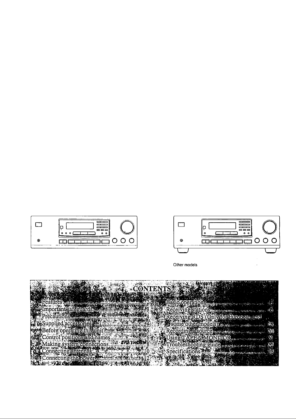
TX-8211
FM Stereo/AM Receiver
Instruction Manual
O“
European and some other models
Page 2

Thank you for purchasing the Onkyo
TX-821 I FM Slereo/AM Receiver.
Please read this manual thoroughly before making con
nections and operating the unit.
Following the instructions in this manual will enable
you to obtain optimum performance and listening
enjoyment from your new Receiver.
Please retain this manual for future reference.
FOR U.S.A. MODEL
Note to CATV system installer:
• This reminder is provided to call the CATV system installer’s
attention to Section 820-40 of the NEC which provides guide
lines for proper grounding and, in particular, specifies that the
cable ground shall be coimecied to the grounding system of the
building, as clo.se to the point of cable entry as practical.
FOR^ANADIAN MODEL i^ y
POUR LEiiMODEUE CANADiEN^ ^'
Features
I Power output
USA & Canadian models:
50 watts per channel, min RMS, at 8 ohms, both
channels driven from 20 Hz to 20 kHz, with no
more than 0.08% Till).
European models:
2 X 70 watts at 4 ohms, 1 kHz (DIN)
Asian models:
2 X 00 watts at 4 ohm.s, 1 kHz (EIAJ)
I Discrete output stage circuits for true high-current,
low-impedance drive
I
Costly, high-quality parts such as large power tran
sistors, an oversized isolated transformer and heavyduty extruded heat sink makes it possible to accu
rately and effortlessly drive 4-ohm s|)eakers (rare for
a receiver)
I
4 Audio inputs
I
A/B Speaker selector and outputs
I
Cassette tape dubbing capability
I’
Selective tone control
I
2-Mode APR (Automatic Precision Reception) (local/
DX, aulo/inono)
I
30 FM/AM random presets
I
Preset scan tuning
I
3 Station group presets (10 stations per group)
I
RDS with PS, 1*TY, RT, I P (European and some
other models only)
I Direct access tuning
I Motor-driven, precision volume control
I Headphone jack
I Audio mute, sleep timer (via remote)
I Battery-free memory backup
I New non-resonant feel
I New slip-free rotary volume knob
I Rl Compatible remote control
• For models having a power cord with a polarized plug.
CAUTION: TO prevent electric shock, ma tch
WIDE BLADE OF PLUG TO WIDE SLOT, FULLY INSERT.
• Sur les modèles dont la fiche est polarisée.
ATTENTION: pour éviter les chocs élec
triques, INTRODUIRE LA LAME LA PLUS LARGE DE LA
FICHE DANS LA BORNE CORRESPONDANTE DE LA
PRISE ET POUSSER JUSQU'AU FOND.
FOR EUROPEAN MODEL;
Declaration of Conformity
We. ONKYO EUROPE
ELECTRONICS GMBH
INDUSTRIESTRASSE 18/20
82IIOGERMERING.
GERMANY
declare in own responsibility, that the ONKYO prrxluct de.scribed
in this instruction inanu:il is in compliance with the corresponding
technical standards such ;is EN550I3.EN5.V020.EN60555-2,
EN60065
GER.MERING.GERMANY
H. YAMAZOE
ONKYO EUROPE ELECTRONICS GMBH
r,n •■'Wf'- -i
......
¿l ATTENTION FOR BRITISH MODEL ,
Replacement and mounting of an AC plug on the power supply
cord of this unit should be perfomied only by qualified .service
personnel.
IMPORTANT:
The wires in the mains lead are coloured in accordance with the
following code:
Blue: Neutral
Brown: Live
As the colours of the wires in the mains lead of this appliance may
not correspond with the coloured markings identifying the termi
nals in your plug, proceed as follows:
The wire which is coloured BLUE must be connected to the termi
nal in the plug which is marked with the letter N or coloured
BLACK. '
The wire which is coloured BROWN must be connected to the ter
minal in the plug which is nnirked with the letter L or coloured
RED.
IMPORTANT
A 5 amp fu.se is fitted in this plug. Should the fuse need to be
replaced please ensure that the replacement-fu.se has a rating of 5
amps and that it is approved by ASTA or BSI to BS 1362. Check
for the ASTA mark or the BSI mark on the body of the fuse.
IF THE FITTED MOULDED PLUG IS UNSUITABLE FOR
THE SOCKET OUTLET IN YOUR HOME THEN THE FUSE
SHOULD BE REMOVED AND THE PLUG CUT OFF AND
DISPOSED Of- SAFELY. THERE IS A DANGER OF SEVERE
ELECTRICAL SHOCK IF THE CUT OFF PLUG IS INSERTED
INTO ANY 13 AMP SOCKET.
If ill any doubt please consult a iiuulilled electrician.
Page 3
“WARNING”
•TO REDUCE THE RISK OF FIRE OR ELECTRIC SHOCK,
DO NOT EXPOSE THIS APPLIANCE TO RAIN OR MOIS
TURE."
CAUTION:
"TO REDUCE THE RISK OF ELECTRIC SHOCK. DO NOT
REMOVE COVER (OR BACK). NO USER-SERVICEABLE
PARTS INSIDE. REFER SERVICING TO QUALIFIED SER
VICE PERSONNEL."
Important safeguards
1. Read Instructions - All the safety ami operating insirueiions
.should be read before the appliance i.s operated.
2. Retain Instructions - The safely and operating instructions .should
be retained for fulure reference.
3. Heed Warnings - All warnings on the appUimee and in the operat
ing instructions sliould be adhered to.
4. Follow Instructions - All operating and u.se instructions should be
followed.
5. Water and Moisture - Tlie appliance should not be u.sed near
water - for example, near a bathtub, washbowl, kitchen sink, laundry
tub, in a wet basement, or near a swimming pool, and the like.
6. Carts and Stands - The appliance should be used only with a can
or stand that is recommended by the manufacturer.
6A. An appliance and cart combination
should be moved with care. Quick
stop.s, excessive lorce, and uneven PonTAOLE cart warning
surfaces may cause the appliance
and earl conihination to overturn.
WARNING
RISK OF ELECTRIC SHOCK
A
14. Power Lilies - An outdoor antenna should be located away from
power lines.
15. Nonuse Periods - The power cord of the appliance should be
unplugged from the outlet when left unused for a long period of time.
16. Object and Liquid Entry - Care should be taken so that objects
do not fall and liquids are not spilled into the enclosure through open
ings.
17. Damtige Requiring Service-The appliance should lie .serviced
by qualilieil service personnel when:
.A. The power-supply cord or the plug has been damaged; or
13. Objects have fallen, or liquid has been spilled into the appliance;
or
C. The appliance has been exposed to rain; or
D. The tippliance does not appear to operate normally or exhibits a
marked change in performance; or
E. The appliance Inis been dropped, or the enclosure damaged.
18. Servicing - The ii.ser .should not attempt to service the appliance
beyond that described in the operating instructions. .All other .servicing
should be referred ni qualified service personnel.
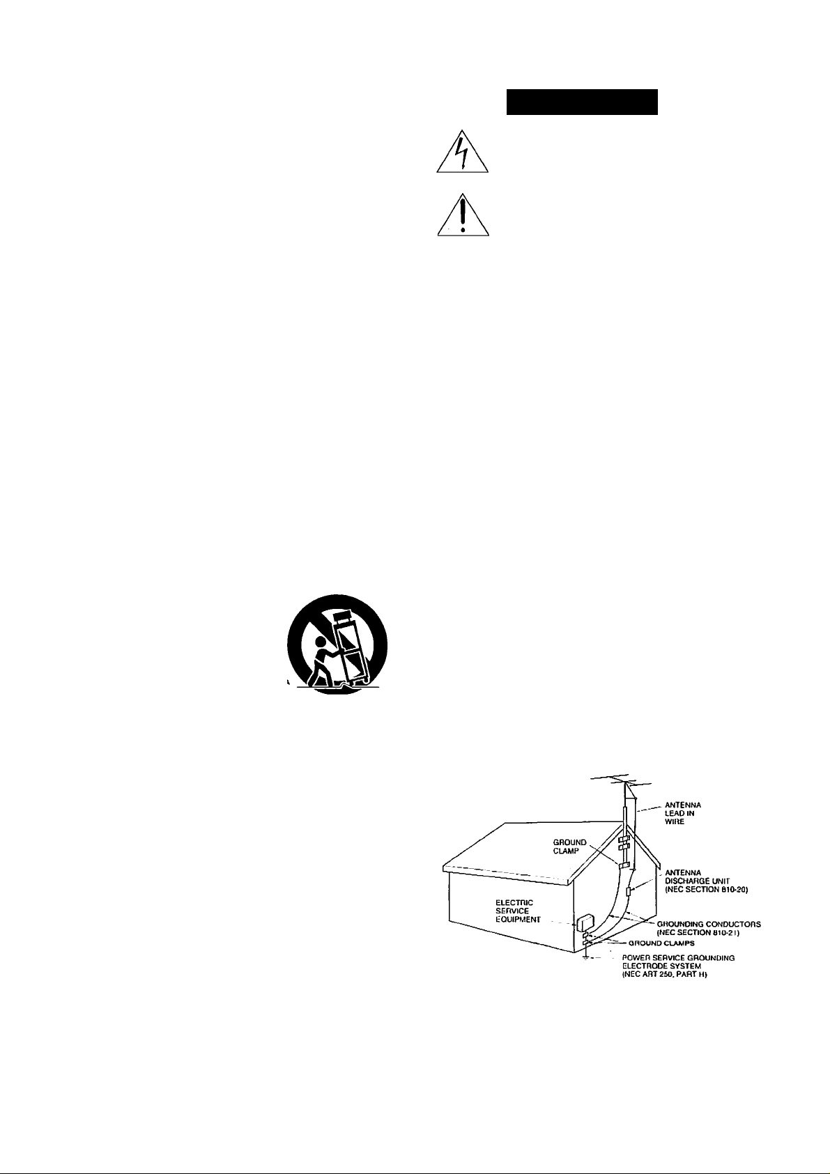
19. Outdoor Antenna Grounding - If an outside antenna is con
nected to the receiver, be sure the antenna system is grounded so as to
provide some proteelion against voltage surges and built up sialic
charges. Article 8 !0 of the National lileclrical Code, ANSI/NIT’A 70,
provides information with regard to proper grounding of the mtisl and
.supporting structure, grounding of the lead-in wire to an antenna dis
charge unit, size of grounding eondiiclors, location of the antenna-dis
charge unit, connection to grounding electrodes, and requirements for
the grounding eleeirode. See Figure 73.1.
DO NOT OPEN
The lightning flash with arrowhead symbot, within
an equilateral triangle, is intended to atert the user
to the presence of “dangerous voltage" within thoi
product's enclosure that may be of sufficient magni
tude to constitute a risk of etectric shock to persons.
The exclamation point within an equilateral triangle
is intended to alert the user to the presence of
important operating and maintenance (servicing)
instructions in the literature accompanying the
product.
A
7. W'all or Ceiling Mounting- The appliance should be mounted to
a wall or ceiling only as recommended by the manufacturer.
8. Ventilation - The appliance should be situated so that its locatioiT or
position does not interfere with its proper ventilation. For example,
the appliance should not be situated on a l>ed,’.sofa, rug, or similar sur
face that may block the ventilation openings; or if placed in a built-in
insiallalion. such as a book case or cabinet ihtit nitty impede the flow
of air through the ventilation ti|K-nings. there .shoiihl lie free space of at
least 20 ctii and open up behitid the appliance.
9.
lletlt -The appliaticc should Ire situated away from heat sources sucfi
as radiators, heal registers, stoves, or other applititices (iticluditig
amplifiers) Ihal produce heal.
10
Power Sources - The appliance should be connected to a power
sitpply only of the type de.scribed in the operalitig imslruciions or as
marked on the appliance.
II
I’olari/.lltioil - If the applitincc is provided with a polarized plug
havitig one blade wider than the other, please reat.1 the followitig infor
mation: The polarizalioti of the plug is a safely feature. The polarized
plug will only lit the outlet one way. If the plug does not lit fully itilo
the outlet, try reversing it. If there is still trouble insciling it, the user
should seek the services of a i|ualilied electrician. Under no circum
stances should the user attempt to defeat the pohnT7.ulion of the plug.
12. Power-Cord Protection - Power-supply cords should be routed so
that they are not likely to be walked on or pinched by items placed
U(ion or against them, especially near plugs, convenience receptticles.
and the point where they exit from the appliance.
13. Cleuning-Thc appliance should be cleaned only as recommended
by the manufacturer.
FIGURE 73.1:
EXAMPLE OF ANTTsNNA GROUNDING
N.ATTONAL ELECTRICAL CODE
NEC - NATIONAL ELECTRICAL CODE
SZSSSA
AS PER
Page 4
Precautions
1. Warranty Claim
You can find the serial number on the rear panel. In case of war
ranty claim, please report this number.
2. Recording Copyright
Recording of copyrighted material for other than personal use is
illegal without permission of the copyright holder.
3. AC Fuse
The fuse is located inside the chassis and is not user-serviceable.
If power does not come on, contact your Onkyo authorized service
station.
4. Care
From time to time you should wipe the front and re;ir panels and
the cabinet with a soft cloth. For heavier dirt, dampen a .soft cloth
in a weak solution of mild detergent and water, wring it out dry.
and wipe off the dirt. Following this, dry immediately with a clean
cloth. Do not use rough material, thinners, alcohol or other chemi
cal solvents or cloths since these could damage the finish or
remove the panel lettering.
5. Power
WARNING
I3EFORE PLUGGING IN THE UNIT FOR THE FIRST TIME,
READ THE FOLLOWING SECTION CAREFULLY.
• Some models are designed for use only with the power supply
voltage of the region where they arc sold.
European and Ausiralian inodelsiAC 230V. 50H/.
U.S. and Canadian models; AC 120V, 60Hz
Worldwide model: AC 220-230V/I20V swilchabic,
50/60HZ
Other: AC 220V, 60Hz
• Voltage Selector (Rear Panel)
Worldwide models are equipped with a voltage selector to con-
, foiln to local power supplies. Be sure to set this switch to
match the voltage of the power supply in your area before
plugging in the unit. (See page 5.) Models wilhout a voltage
.selector can only be u.sed in areas where the power supply is
the same as that of the unit.
• The power does not shut off completely by just turning the
power off. So power cord should be removed froiii AC outlet
when not in use for a prolonged time.
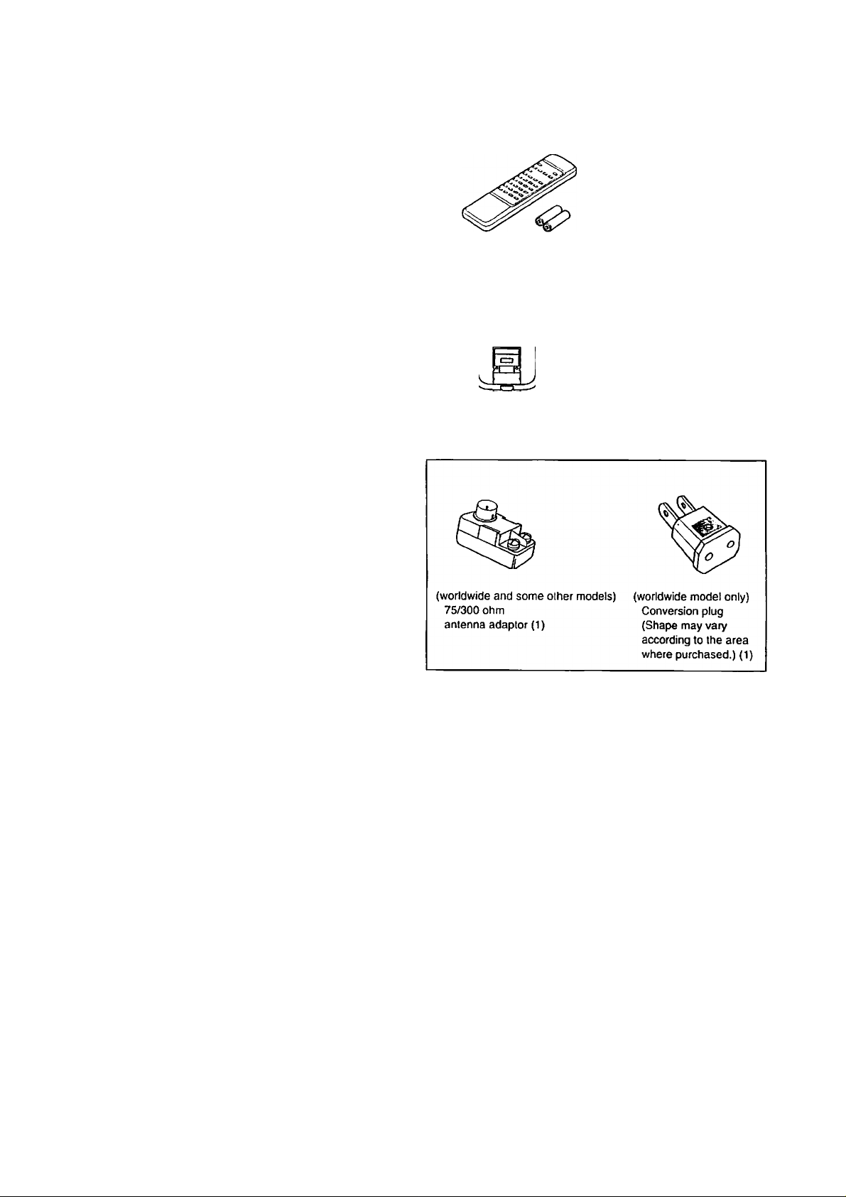
Supplied accessories
Remote control RC-330S (1)
Battery (size AA. R6, or UM-3) (2)
AM loop antenna (1)
T-shaped FM antenna (1)
Memory Preservation
This unit does not require memory preservation batteries. A built-in
memory power back-up system preserves the contents of the mem
ory during power failures and even when the unit is unplugged. The
unit must be plugged in order to charge the back-up .system.
The memory preservation period after the unit has been unplugged
varies depending on climate and placement of the unit. On the aver-
iige, memory contents are protected over a period of a few weeks
after the last lime the unit has been unplugged. This [>eriod is
shorter when the unit is exposed to a highly humid climate.
Page 5
Before operating this unit
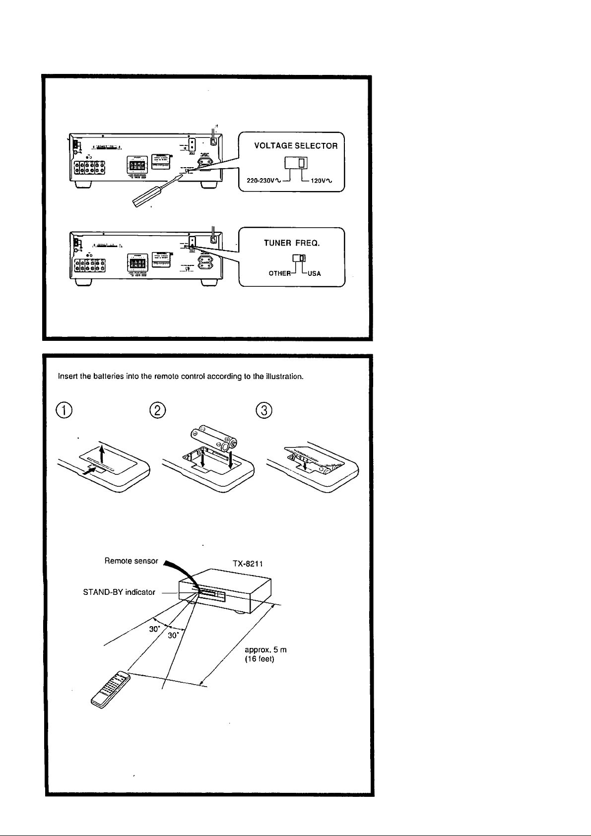
Setting the voltage selector tf'i (worldwide model only), "' ’"f.
. Deteiniine the proper voltage for your
mea: 220 - 230 V or 120 V.
. If the setting on the voltage selector is
not correct, insert a screwdriver into the
groove in the switch and slide the
switch completely to the right (120 V)
or the left (220 ~ 230 V), whichever is
appropriate.
Setting thatuh|ng>tep[^^ . ^
: frequency''''
i: (worldwide rriodel only) •: '
The worldwide model is equipped with a
switch that controls the AM (9 kH/7
10 kHz.) band tuning steps.
Please .set this switch to match the tuning
step frequency in your area.
U.S. & Canada: USA
Other areas: OTHER
Using the remote control
The following information will help you
get optimal use from the remote control.
• Place this unit away from direct bright
light which c:in prevent proper opera
tion of the remote control.
• Mttke sure audio rack doors do not have
tinted glass. Placing this unit behind
such a door may prevent proper remote
control operation.
Loading the batteries , •i
Remove the battery compartment cover by
opening it as shown in the illOistration.
Load two AA (R6 or UM-3)-size batteries
into the remote control with the plus (+)
and minus (-) tertninals positioned as indi
cated by the diagram inside the battery
compartment, then close the cover.
• Immediately remove empty batteries to
avoitl corrosion damage.
• To avoid potential conosion damage,
never mix old batteries with new ones.
• The manganese batteries supplied with
this unit have a .service life of approxi-
mtitely six months, dependitig on the
frequency of use.
• The TX-8211 comes equipped with two
AA (R6 or UM-3) manganese batteries,
but we recommend that long-life AA
(LR6 or AM-3)-size alkaline batteries
be used when replacing the batteries.
Page 6
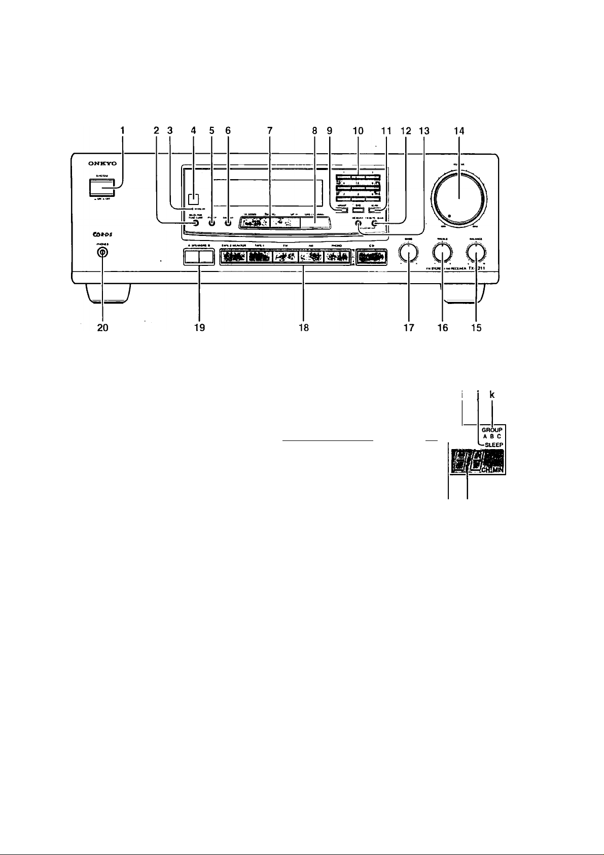
Control positions and names
other than USA & Canadian model
USA and Canadian model
1
For more information about buttons or
knobs, turn to the page number listed in [ ].
1. POWER (or SYSTEM) switch
112J
2. SELECTIVE I'ONE CONT
button [13]
3. STAND-BY indicator |12|
4. Remote sensor [5]
5. P l'YAl'P button [19]
(Only for European and some
other models)
6. DISPLAY button [19]
(Only for European and some
other models)
7. ◄ DOWN, UP ► TUNING
buttons [15]
8. DIRECT TUNING button [15]
Display
ЛГгт-тА P R
BF r STEREO
MODEST, MODE
[ЕНП^ЕШЗ
Bini' ПЕНЕ!
SPEAKERS A 8 AUDIO MUTE FM MUTE ► TUNED < MEMORY
'hT-2 monitor! IsTcl ON OFF ^STEREO ^-tlBia
ÌIÉ iWiHWl
mi mi inM miMm /zi^/
9. GROUP button [16,17] b.
10. Number buttons [15-17]
11. SCAN button [17,19] c.
12. FM MUTE/MODE button [16,17] d.
13. MEMORY button [16, 17] e.
14. VOLUME knob] 13] f.
15. BALANCE control knob [13] g.
16. TREBLE control knob [13] h,
17. BASS control knob ]13] i.
18. Input selector buttons 113] .]■
19. SPEAKERS A/B IniUons [ 13] k,
20. 1 leadphouejack]14] 1
: Display
- - — - # —
If (here is a protective Him on the surface R'
of the display which is making it dilTicult
to read the display, remove it.
a. APR indicators
g h
m I
T-2 MONITOR (Tape-2
Monitor) indicator
Speaker selector indicators
AUDIO MUTE indicator
Selective Tone Control indicator
FM MUTE ON/OEF indicator
STEREO indicator
TUNED indicator
MEMORY indicator
SLEEP indicator
(¡ROUP indiciitors
Preset station/sleep timer
displiiy
RDS indicator (Only for
luiropean atid some other models)
Multi function display
Page 7
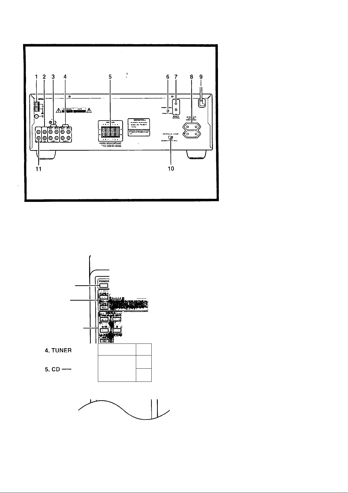
Control positions and names
1. ANTKNNA terminals [llj
2. CD input connectors [8]
3. TAl’E-1/lNl’UT/OUTPUT
connectors [8]
4. TAI»i:-2 INrUT/OUTPU r
connectors [8]
5. SPEAKERS terminals [9]
6. TUNER FREQ. (Tuning Step
Frecpiency) switch [5]
(Worldwide model only)
7. RI REMO TE CONTROL
connectors [8]
8. AC OUTLETS [9]
9. Power supply cord [12]
10. VOLTACiE SELECTOR [5)
(Worldwide model only)
11. PHONO input connectors [8]
1. POWER
2. INPUT
SELECTOR
3. DECK-A/DECK-B
INPUT SIieCTOR :
Ишикщшьси]
P."U .'tWiN. .
ONKYO
REMÜÍE CONTROLLER МС i>n
1
тГТП
MUTING
[ЦЬ
jv'a-.i
CZl
□
T
6. SLEEP
7, MUTING
8. VOLUME
Remote Control i
" t ■'
m
1. POWER hutton [12]
2. INPUT SELECTOR buttons
[13]
4. TUNER operation buttons 117]
GROUP : Group button
.^PRESET ► ;Pivset memory up/
down buttons
6. SLEEP btttton [14]
7. MUTING button [14]
8. VOLUME
When you liiive made the connections
mentioned on page 8, you will be able to
use the Ibllowing buttons.
A/T
buttons [13]
3. Tape deck operation buttons
(DECK-A, DECK-B)
; Reverse play button
: Forward play button
-4-4 : Fast rewind button
► ► : Fast I'oiAvard button
■ : Stop button
•/|| ; Rec/pause button
M: When only a single deck is used,
oix;nite DECK-B.
5. CD player operation buttons
(CD)
■ : Slop button
: Pause button
II
: Play button
: Down button
1-44
; Up button
► ► 1
: Disc button for CD changer
DISC
Page 8
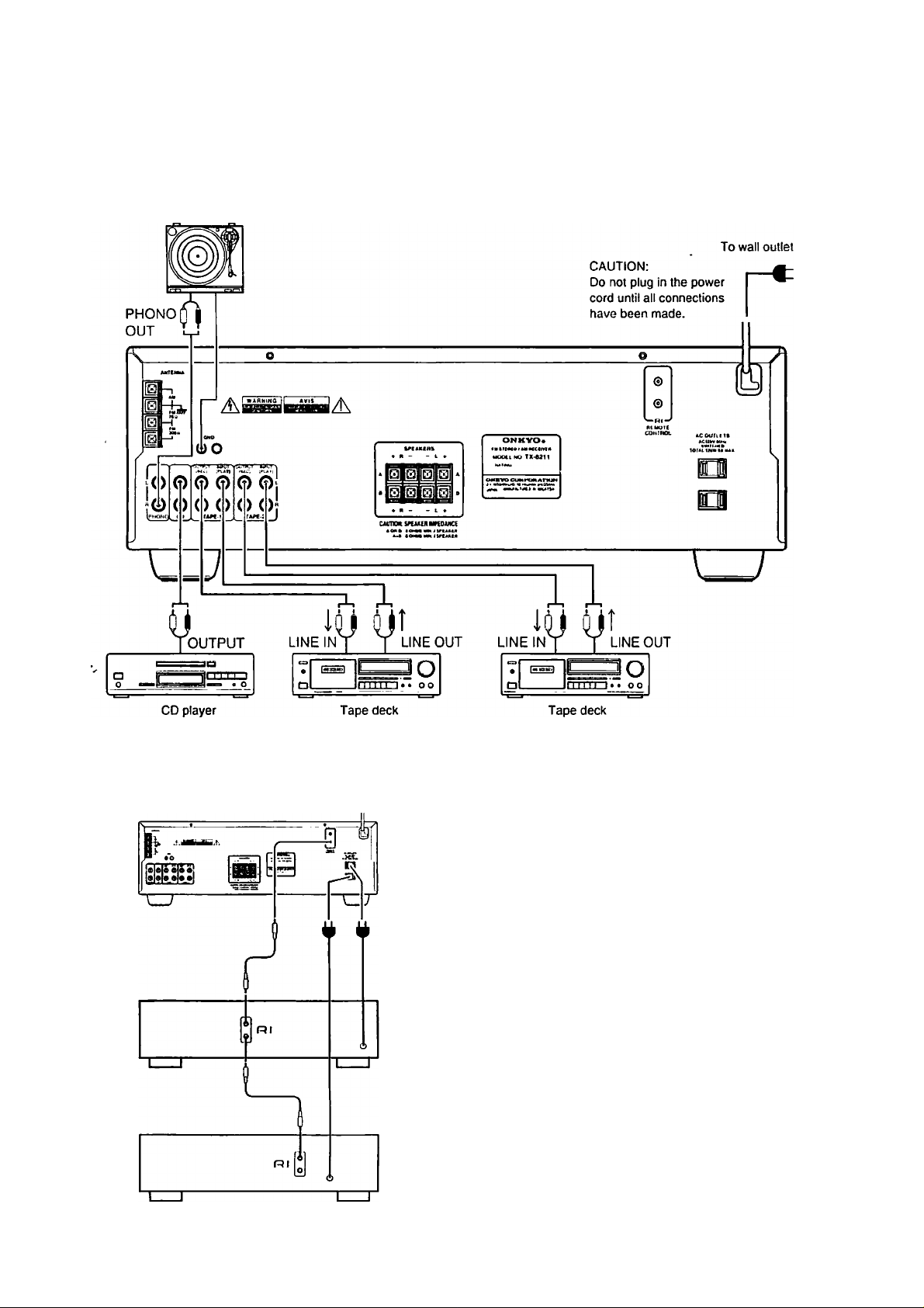
Making system connections
Refer to the insiniciion manual of each component when making connections.
On each pair of connectors, the connector (red and marked R) corresponds to the right
channel and the connector (white and marked L) to the left channel.
Turntable
TX-8211
Cassette tape decks and a compact disc player that are equipped
with an Onkyo Rl connector can be operated using the remote
control included with this unit.
To enable remote control operation of other components, connect
the remote control cable as shown at the left.
NOTK:
• To enable proper remote control operation, both the RI cables
and the audio cables must be connected to the units.
• This unit’s remote control cannot be used to control Onkyo
tnrntable.<t.
• An RI remote control cable equipped with 1/8" (3.5 mm) mini
jacks is included with any other component installed with an
Rl connector.
8
Page 9

Making system connections
The power to components connected tq the
SWITCHED outlet is turned on and off
using the POWER switch (or the SYSTEM .
switch on models other than USA and
Canadian models) on the front panel and
remote control.
NOTE:
• The shape, number and total capacity of
the AC outlets may differ according to
the model and the area where the unit is
purchased. 13e careful that other compo
nents connected to this unit do not
exceed the capacity that is printed on
the rear panel above the AC outlets.
• (For the European model)
The remote control cannot be used
when the SYSTEM switch on the front
panel is set to OFF.
SPEAKER A
R
SPEAKER B SPEAKER B
^ SPEAKER IMPEDANCE
SPEAKER A
L
CAUTION:
A or B:
4 ohms min./speaker
A-r B;
8 ohms min./speaker
Connecting the speaker
■V)“*
cables '
1. Open the lever.
2. Twist wire ends very, tight, and insert
the wire.
3. Clo.se the lever.
Before making any connections, please
refer to the explanation of “Speaker imped
ance".
Speaker Impedance
The load impedtincc of each speaker sys
tem connected to this unit must be at least 4
ohms. (If using only A or only B, 4 ohms
min.; if A and B, 8 ohms min.)
You can connect two separate pairs of
speaker systems.
Please connect each speaker according to
the illustration, observing the correct con
nections for R. L, and -.
• Do not u.se unnecessarily long or
extremely thin speaker leads. If the DC
resistance of the s()eaker leads is too
high, the damping factor will decrease,
adversely affecting the sound quality.
• When using only one .speaker or when
you wish to li.stcn to monaural (mono),
the single spetiker should never be con
nected in parallel to both the right and
left channel terminals at the same time.
wu
Note:
To prevent damage to circuitry,
never short-circuit the positive (+)
and negative (-) speaker wires.
0 o
)
C
“A
11
1 o c
♦ -
R
O
Page 10

Connecting antennas
1. Open the lever.
2. Twi.sl wire ends very light, and insert
the wire.
3. Close ihe lever.
- Vf-
AM loop'antenna
A.ssemble the loop antenna as shown in the
illustration. (Refer to the next page for
details on connecting the AM loop
antenna.)
SIIID
[ 75/300 ohnf adaptor ^
' (worldwide and sorne other
models) ' ='
Connecting the 300 ohm ribbon wire to
the 75/300 ohm adaptor
Loosen the screws and wrap the wires
around them. Then, tighten the .screws with
a screwdriver.
Connecting the coaxial cable to the 75/
300 ohm adaptor
1. With a small screwdriver, pull Ihe stop
pers outwards and remove the cover.
2. Remove the transfonner wire A from
slit B and in.sert it into slit C.
3. Prepare the coaxial cable as shown in
the illustration. Connect the coaxial
cable to the 75/300 ohm antenna adap
tor.
© Insert the end of the cable.
@ Use pliers to pinch it and keep it in
place.
4. Re-install the cover.
10
- -r-'
^Directional linkage
Do not use Ihe same antenna for both FM
and TV (or VCR) reception since Ihe FM
and TV (or VCR) signals can interfere with
each other. If you must u.se a common FM/
TV (or VCR) antenna, use a directional
linkage type splitter.
i: to -
Page 11

Connecting antennas
The T-shaped FM antenna is for indoor use only. Extend the antenna and move it until the clearest signal is received. Use tacks or similar
objects to fix it in the T-shaped arrangement giving the least amount of distortion.
Tlic AM loop antenna is also for indoor use onl^. Position it where the clearest sound is received. Put it as far as possible away from this
unit, the TV, speaker cables and power cords.
If clear signals cannot be received using only the enclosed T-shaped FM antenna or AM loop antenna, connect an outdoor FM or outdoor
AM antenna as needed.
Others
OUtdobKAlVvianterin ' i > t .
The outdoor AM tintenna will be more effective if it is stretched horizontally above a window or outside. (Do not disconnect the AM loop
antenna.)
Others
[, Outdoor F
Outdoor FM antenna
Be sure that the outdoor FM antenna is positioned as follows:
• Keep the tintenna away from noise sources, such as neon signs and busy roads.
• Do not position it near |»wcr lines, etc. This is very dangerous.
Others
11
Page 12

Connecting the power
Before plugging in the unit, confirm that all connections have been made properly.
Before turning on the power, be sure that the VOLUME knob is fully turned counterclockwise.
Turning on this unit’s p>ower may cause a momentary power surge, which might interfere with other electrical equipment, such as comput
ers. If so, use a wall outlet on a different circuit.
U.S. and Canadiiiii models:
Plugging the TX-82U’s power cord into an AC outlet puis tlie
POWER switch
SYSTEM switch
unit in stand-by status (the STAND-BY indicator is lit). Pressing
the POWER switch turns on the unit and lights up the display. If
this switch is pressed again, the unit returns to the .stand-by status.
Tlie POWER button on the remote control is u.sed in the same way
as the POWER switch on the TX-8211.
Models other than U.S. and Canadian models:
After plugging the TX-8211's power cord into an AC outlet, pre.ss
the SYSTEM switch to pul the unit in power-on status (the unit
tan be operated and its display is lit). The remote control cannot
be used to operate the TX-8211 if the SYSTEM switch is not set to
ON.
When the SYSTEM .switcli is set to ON, pressing the POWER but
ton on the remote control switches the TX-8211 between stand-by
status (the STAND-BY indicator is lit) and power-on status (the
display will light up).
Pressing the SYSTEM switch on the TX-8211 to .set it to OFF
turns off the unit. (When the SYSTEM switch is set to OFF. only a
small amount of power is used.)
12
Page 13

Basic operations
TAPS 2 MONITOR lARE-l fM
AM PHONO
A SPAAKERS D
1. Select the source you wish to listen to
using the input selector (c.g. PHONO).
Confirm that the I T-2 MONITOR | indi
cator is not lit when a source other than
ТАРП-2 MONITOR has been selected.
Also check that the AUDIO MUTE
indicator is not lit.
2. Select the speakers.
Select and press the button for the
speakers that you want to listen to
(SPEAKERS A and/or SPEAKERS B).
The corresponding A and/or В indicator
lights up on the display panel. You will
hear from the speakers any sound going
through this unit. If both SPEAKERS
(A and B) are set to OFF, no sound will
come from the spieakers.
3. Start playing the selected input source.
Follow the operating instructions for
that unit.
If FM or AM is selected, refer to
“Receiving stations".
4. Adjust the level.
Turn the VOLUME knob clockwi.se or
press the UP button on the remote con
trol to increase the volume level. Turn
the knob counlerclockwi.se or press the
DOWN button on the remote control to
decrease the volume level.
5. Adjust to your desired tone.
BASS: Turn clockwise to boost or
counterclockwise to attenuate the bass.
TREBLE: Turn clockwise to boost or
counterclockwise to attenuate the tre
ble.
SELECTIVE TONE CONT: Press
this button to clearly reproduce ulu-alow and -high frequencies. The SELEC
TIVE TONE indicator lights up on the
display panel.
fi. The BALANCE knob is used to con
trol the relative volume level of the
left and right speaker systems or
headphones.
NOTE:
The power does not shut off completely by
just turning the power off. The power cord
should be removed from the AC outlet
when not in use for a prolonged time.
, . ......Vi;.. _ --H
The direct function feature
When a compact disc player and tape deck
with the Rl jack are connected together,
you can use the direct function feature.
Simply by directly operating the desired
component (comptict disc player or tape
deck), this unit’s input selector automati
cally switches to that component.
It is not necessary to switch this unit’s
input .selector when changing listening
sources.
13
Page 14

Basic operations
'1^'^
B izJia Esr
■:—7—TT
□ CD cu
s □ □
AUOOHUTc
^íLlatenlhg^Ing théH’ea
Stereo headphones with a standard binaural
(stereo) plug can be connected to the
PHONES jack.
When the headphone plug is inserted, the
speakers are not automutically muted but
can be controlled with the SPEAKERS A/
B buttons.
Temporal^ Muting
Press the MUTING button on the remote
control.
This button temporarily switches off the
sound from the speakers or headphones.
The AUDIO MUTE indicator will flash.
The muting function will be cancelled if
you:
• press llie MUTING button again, or
• turn the power off then on.
RC-330S
d cc
_/(_ L <_
-SO
Cancel 10 20
o
SO 70
Sleep facility
The sleep timer can power off the system
after a specified time period.
To operate this function, use tfie remote
control supplied with yourTX-8211.
f. Start the source playing that you
would like to listen to (CD, Tape or
radio broadcast).
2. Set the amount of time after wliich
you want the .system to turn off.
The sleep timer works for up to 90 minutes.
You can shorten the timer by 10 minute
increments by pressing the SLEEP button
until the desired time h.as been reached.
After the set lime passes, the power will be
switched off automatically.
Cancelling the Sl.EEP setting
The timer wili be canceiied if you:
U! I
-lu
1
• pre.ss the SLEEP button until it changes
to the display of the source you are lis
tening to, or
• turn off the pow'er while the timer is
operating.
1
14
Page 15

Receiving stations
г
I I I
2
I I I
h't
h'l
UI..I I II I
-J u. и
I II I
Please make sure lhai the IT-2 MONITOR I
and AUDIO MUTE indicators are not lit.
Tuning the radio (Mahui^'^ tuning and Direct tunlHg)'^;í^Í
When the frequency is not known (Man
ual tuning)
1. Press the FM or AM button.
2. Use the ◄ DOWN TUNING UP ►
buttons to change the frequency.
UP
.............
the frequency increases.
DOWN the frequency decreases.
• The frequency is changed in 100 kHz
(or 50 kHz) steps in FM and 10 kHz (or
9kHz) in AM each time a tuning selec
tor button is pressed.
• If a button is held continuously for
more than 0.5 seconds, the frequencies
are scanned automatically. (FM auto
tuning mode)
When a broadcast is received, scanning
' stops.
OOMH TumnG
taHtCT lUMiHC
a
i.lh'l I ..I i, I I
I II I li. L'U"*
I h/l LJI-'I
III I II I
I h'l
I lb
_____
.
When the frequency is known (Direct
tuning)
1. Press the F.M or AM button.
2. Press the DIliECl' TUNING button.
The will flash for 16 seconds in
the frequency display.
i. Enter the frequency with the number
buttons while the cursors are flash
ing.
E.xample: K8.10 M Hz 8 ^ 8 I -» 0/10
• When receiving AM broadcasts with a
9 kHz step (this depends on your
region), you can enter the frequency
directly.
With 10 kHz steps, entering a number
for the 10 kHz digit will .set the 1 kHz
digit automatically to 0.
• If you enter a frequency that is out of
range, this unit will return to the previ
ous frequency. If this happens, repeat
the procedure.
I. I''I i.jO
I I I uu.^- '-
о
L. b'l
I I I
I II. I III
U U. I L/„
15
Page 16

Receiving stations
ir you tune in a stereo FM station, the STEREO indicator will be
illuminated if the signal is sufficiently strong.
If the signal is weak, it may be impossible to tune into your
desired station. In this case, tunc in as follows.
Press the FM MUTE/MODE button and FM MUTE OFF lights up.
At this time, the station will be in mono and interstation noise will
be heard.
Select the station you want to listen to.
This unit is equipped with an APR system to help tune in FM sta
tions.
When receiving an FM station using manual or direct tuning, RF
MODE LOCAL/DX and STEREO MODE AUTO/MONO settings
are made automatically, according to the station being received.
The APR system automatically sets the gain of the RF section to
DX or LOCAL according to the quality of the signal being
received. The RF MODE will indicate LOCAL when a sufficient
signal is received.
If the MONO indicator lights up while a station is tuned in. the
station will be received in mono even if it is a stereo station.
The STEREO MODE AUTO/MONO settings that the APR system
makes can be changed by pressing the FM MUTE/MODE button.
MMOftv <wacc
i iir*%TEf€0
uot*^ Mooe
UU*I
mnrm
r I I U I 111
r I I -lU.UUu.
I h/ l I. II .1 I I I I
ril _/(_/. u<_/_
3 2
1 h/l
1 1 1
t » IUU> «
ON
»1640
1 II 1 n 1
D U. -1
\.“®'
; Programming radio stations- J
Since ten AM or FM stations can be stored
in each group (A, D or C), a total of 30 sta
tions can be stored in the memory.
1. Select the frequency that you want to
store in the memory.
(Refer to “Tuning the radio" on page
15.)
2. Pre,ss the MEMORY button.
The MEMORY indicator will light for
8 .seconds.
3. While the MEMORY indicator lights,
press the GROUP button to choose
CM
0^
the desired group.
The group shown on the display
changes in the following order each
time the button is pressed: A —» B —> C
^A...
4. Select (he desired memory num
ber using the number buttons.
Press button 0/10 when choosing mem
ory number 10.
NOTE:
If the FM station received is an RDS sta
tion with a PS (Program Service Name),
the frei|uency display will change to the PS
display. II' there is no PS, the frequency
display will not change.
(Refer to pages 18 and 19 for more details
on the RDS function.)
16
I h 'l I I I. J I II I
i'll -lU.UU^
-L.
Page 17

Receiving stations
I I
First, select the tuner as the source by
pressing the AM or FM input selector but
ton on the main unit or TUNER input
selector button on the remote control.
Miiin unit
1. Press the GROUP button to select the
tleslretl group.
2. Input the memory number you wish
to receive by using the number but
tons. ■
or
Press the SCAN button.
Each station stored in the group chosen
in step I will be received for 5 seconds.
When the station that you want is
found, press the SCAN button again
and scanning will stop.
Remote control
1. I’rcss the GROUP button and cboose
the group.
2. Pre.ss the PRF.SKT or ► button.
After the last number of GROUP C is
reached, scanning will restart at GROUP
A.
Cancelling preset stations' i '
1. Select the station that you want to
cancel as e.xplained in the previous
.section.
2. Press the FM MUTli/MODE button
while holding down the .MEMORY
button.
will be shown on the display.
__
MucE Moce
msm
wewonv rwwu*f'MC«t
itf SIE№0
,l
_
WIW»1
1 . h'l I.JI.J till
Í 1 1 _M_/.
> UWU'i > >UM u «
on S’CNIO
^ U£MÚ>«t _ utmX*'
1
17
Page 18

R6C6iving RDS (Only for European and some other models)
RDS reception is only in areas where RDS broadcasts are avail
able.
What is RDS?
Many FM stations now transmit RDS signals which give addi
tional information. RDS provides you with various services so
that, for example, you can choose a station brotidcasting your
favorite category of music or other information. The information
shown at the right is available on this unit.
NOTE:
In .some cases, the characters displayed on the display of the TX-
8211 may not be exactly the same as the ones broadcast by the
radio station. If strange characters appear in the di.splay, it is
because characters are being received that cannot be correctly dis
played by the TX-8211. They do not indicate a malfunction of the
unit.
PTY Classiiication.s in Europe
0
1
hi n til r
I'l LJ I'I L.
>'! > ! O
I 'I t_ h 'l J
None
News reports
No program type or undefined.
Reports on current events and happenings.
PS: Program Service Name
l*'I’Y: Program Type
I P: Tramc Program
RT: Radio Text
2
RFFRIR^
3
4-
5
6
7
8
9
10
11
12
13
T hi r n
M I'l f
RPRR T
p V I I r p T p
L
U U L.
l1
HRRriR
rill T I! p p
t_ u t_ I u r> L
p r r p hi r p
J 1_ ± L I 'I L L
I'RRIES
o n o
1 U /
p n r p M
t' U U I' II
AW
n
; /
I T p U T
l_ ±0/7 '
S l\ »
' u
Current affairs
u
I L.
AW
/ /
p
Information
Sport
Education
Drama
Culture
Science and technology Programs about the natural sciences and technology
Varied
Pop music Popular commercial music, usually included in past or present sales charts.
Rock music ' Popular music with a more specialist appeal, often not included in sales charts.
AW
Middle of the road music Easy listening music as oppo.scd to Pop, Rock or Classical.
1 1
h>l
Light classics
I I
Topical reporting of current afl'airs, often with a wider range of topics than news
reports.
General information such as weather forecasts, consumer affairs, medical help,
etc.
Live .sports action, sports news and interviews.
Formal educational programs.
Radio plays and .serial.
Cultural progrtims (including religious affairs).
Speech based programs not covered by the above categories, eg. quiz/es, pattel
games, comedy, etc.
Classical music for general rather than specialist appreciation.
18
14
FLRRRIFF
n T U P P
15
U I / 7 t_ /'
A//
I I
Serious classics
Other mu.sic
Performances of major orchestral works, sytnphonies, chamber music, etc.,
including Grand Opera.
Music styles not covered by the above categories, eg. Jazz, Rhythm & Blues,
Folk, Country, Reggae.
Page 19

Receiving RDS (Only for European models)
PTY/TP DOWN TUNING UP ► SCAN
Searching for a station which broadcasts ybur’ ^ favorite category (PTY scian)" f r-^
I’ress the P TY/TP button, to select “1*TY”.
If the station you are receiving is not broadcasting RDS, ‘Not
RDS” (this is not an RDS station) will be shown on the display.
Use the ◄ DOWN TUNING UP ► buttons to select the
program type (PTY), for example, “ROCK M”.
See the PTY description on the previous page.
Pre.ss the .SCAN button to start seiirching for the chosen
PTY station.
When a station is received with the desired PTY, the .scanning
stops for approximately 5 seconds, before the unit starts scan
ning again.
When the desired station is reached, press SCAN button
again to stop scanning.
Receiving RDS traffic Information
I’ress the I’'I'Y/TP button to select "TP”.
If ! ¡ P i is shown on the display, it indicates that the current
station is broadcasting traffic information.
Pre.ss the SCAN button to start searching for a Ti’ station.
When the unit receives a TP station, it stops scanning. If the
unit cannot receive any TP station, “Not find” (cannot find the
station) is shown on the display.
Displaying Radio Text (RT)
If the station you are listening to is not an RDS station, this func
tion cannot be u.sed.
1. Each time you press the DISPI.AY button, tlie display
changes ¡»s follows.
j-» I'rciiuency
Radio Text <—
If the current station you are listening to is not an RD.S station,
only the fret|uency of the station appears.
When RT is received, it can sometimes Uike up to 15 seconds (more
or less) to show RT on the display.
Sometimes the following mes.sagcs will be shown on the display.
Wail: When the information is received, the characters will scroll
across the display.
No text: This appears for 3 seconds and indicates that even though
an RDS station is being received, there is no RT inlormation
included.
Program Service Name
_____
I
t -
19
Page 20

Recording a source
TAPC-2 MONnOfl TAPE«! FM AM PmOnO
TX-8211
Recording
Tape dock
(TAPE-1 and/or TAPE-2)
I
Playback
Turntable
CD player
Please read ihe insiriiciion manuals con
cerning ihe operation of each unit.
1. Insert a blank tape into the tape deck.
2. Press the button (other than TAPE-2
MONITOR) of the source from
which you want to record.
• When FM or AM is selected, set the
tuner to the station you want to record
from.
• When TAPE-1 is selected, it will record
to the TAPE-2.
• When either FM. AM, PHONO or CD
is selected, you are able to record to
both the TAPE-1 and TAPE-2.
3. Put the tape deck in the recording
mode. Begin playing the source.
Set the proper recording level using the
controls on the tape deck used for record
ing. Also, if any controls (bass, meble etc.)
on this unit are changed during recording
and dubbing operations, the tone effects
will not change.
NOTE:
Recording from TAPE-2 to TAPE-1 is not
possible.
Recording
Tape deck (TAPE-2)
"'Tap^
1. Load the original tape in deck 1 and
the blank tape in deck 2.
2. Press the TAPE-1 button.
3. Put tape deck 1 in the playback mode
and tape deck 2 in recording mode.
TX-8211
Playback
Tape deck (TAPE-1)
20
Page 21

Using TAPE-2 MONITOR
Unless the coinponeiu eonnecled to the TAPE-2 connectors is to be used, the I T-2 MONI I OrI indicator in the ninin unit's display should not
be lit; otherwise, the sound from other sources cannot be heard.
If a 3-head tape deck is connected to the TAPE-2 connectors, 3 APE-2 MQNI TOR ctin be used to monitor the recording.
NOTE
Even when TAPE-2 is not selected as the source (the I T-2 MONIToiTI indicator is not lit), the source signal is still .sent to the TAPE-2 output.
Monitoring during recording, ^
The source signal can be nionitured
through the speakers or headphones
when TAPE-2 MONITOR is turned off.
TAPE-2 MONITO«
$
TX-8211
If Ihe I T-2 monitor! indicator in the dis-
|ilay is not lit, Ihe sound from the source
can be heard. If the 3-head tape deck con
nected to the TAPE-2 connectors is used
for recording, press either the TAPE-2 but
ton on the remote control or the TAPE-2
MONITOR button on the main unit to
make ‘■ TAPE-2” appear in the display for a
few seconds, light up the | T-2 MONITOR |
indicator, and hear the sound that is just
recorded.
To return to listening to the source sound,
press either the TAPE-2 button on the
remote control or the TAPE-2 MONITOR
billion on the main unit and the
I T-2 MONITOR I indicator goes off.
or Graphic Equalizer
Using a graphic equaiizer
■l i '.O tni»«.
1. Connect the graphic equalizer to the
TAPE-2 connectors on the rear panel
of the TX-8211.
2. If a .second tape tieck is used, connect
it to the tape deck connectors on the
graphic equalizer.
3. Press the TAPE-2 button on the
remote control or the T.AI’E-2 MON
ITOR button on the main unit.
The I T-2 MONlfoiTI indicator on the
main unit's display lights up.
4. Follow Ihe operating instructions for
Ihe graphic eqnali/.er.
To record an equalized signal, use the
tape deck connected to the equalizer.
21
Page 22

Troubleshooting guide
II a problem occurs, while you are using the remóle control, first operate the unit using the front panel controls to confirm that it is not due
to a malfunction (or expired batteries) of the remote control.
Trouble
No power
Power but no sound
Hum. low-lrequency noise
Howling when the volume is
turned up
Rough or scratchy sound;
High range Is not clear
AM stations cannot be
received.
Buzzing noise on AM
(particularly conspicuous at
night or with weak stations)
High-pitched noise or
buzzing noise on AM
Crackling noise on AM or FM
FM TUNED and STEREO
indicators light but sound is
distorted and stereo
separation is bad.
FM TUNED and STEREO
indicators flicker and hiss is
heard on FM.
No station Is recalled when a
PRESET or SCAN button is
pressed.
The RDS function does not
work.
Front panel controls function,
but remote control does not.
Cause
• Power cord is disconnected.
• There is external noise in the computer circuits
of this unit.
• AC fuse is blown.
• |T-2 MONITOR 1 indicator is lit.
• AUDIO MUTE indicator is lit.
• Bad/incorrect connections
• Amplifier protection circuitry has been acti
vated.
• Poor or no input ground
• Poor or no phono motor ground
• The placement of the audio connection cables
on the rear panel Is Incorrect.
• Turntable and speakers are loo close together.
• Stylus of turntable pick-up is worn.
• Turntable stylus tip Is dirty.
• Treble control is too high.
• AM loop antenna is not attached. • Connect the included AM loop antenna to the
• Noise from electrical apparatus such as fluo
rescent lamp
• Noise from the TV set
• Noise caused by turning fluorescent lamp on
and off
• Noise from automobile ignition
• Station is loo strong.
• Multiple reflection ol the radio waves because
of tall buildings or mountains
• Station is too weak.
• Stereo FM broadcasts cover only about half
the distance of an ordinary broadcast.
• The power cord has been unplugged lor a long
time.
• It is not RDS station.
• The reception station signal Is loo weak.
• Too much interference
• No batteries in remote control.
• Batteries have worn out.
• Connect power cord.
• Turn the power switch off, and then on again
or remove the AC plug from the outlet and then
plug it again.
• Contact your Onkyo Service Center.
• Switch ofl.
• Switch off with the remote control.
• Check connection cables, speaker cables, etc.
• Contact your Onkyo Service Center.
• Check outer conductor of input plugs.
• Check lor proper ground connection.
• Adjust the placement of the cable to reduce
hum.
• Move them farther apart.
• Replace.
• Clean.
• Turn treble control down.
AM antenna terminals.
• Move the AM loop antenna to a different posi
tion.
• Set up an outdoor AM antenna.
• Place the AM loop antenna as far as possible
from the TV.
• Move unit away from TV set.
• Move antenna as far as possible from the fluo
rescent lamp.
• Install an FM outdoor antenna as far as possi
ble from the road.
• Change the position or direction of the outdoor
antenna.
• Change to a T-shaped antenna.
• Use an antenna which has better directivity
and select a point where the distortion is least.
• Install an outdoor FM antenna.
• Change the position or direction of the outdoor
antenna.
• The memory contents are lost. Store all sta
tions again.
• Receive an RDS station.
• Install an outdoor FM antenna.
• Change the position or direction of the outdoor
antenna.
• Move the antenna as far away as possible
from the fluorescent lamp.
• Install an outdoor FM antenna as far away as
possible from the road.
• Insert batteries.
• Replace batteries.
Remedy
• ALso refer to the respective instruction manuals of the CD player, cassette recorder, etc., lieing used.
22
Page 23

Specifications
AMPLIFIER SECTION
I’ower Outpui:
USA & Canudian inudcis:
European models:
Asian models:
Dynamic power utilpiil:
USA & Canadian models:
Other area models:
Tolal Ihirmonic Disloilion:
IM Distortion:
Damping Factor:
Input Sensitivities and Impedance:
PHONO: 2.5 mV. 50 kohms
Line (CD. TAPF--1.2): 150 mV. 50 kohms
Output Level and Impetlance:
Rcc out (TAPE-1.2):
Phono Overload:
Frequency Response:
RIAA Deviation:
Tone Control:
BASS:
TREBLE:
Signal-to-Noise Ratio:
PHONO:
CD/TAPE:
Muting:
50 watts per channel, min RMS. at 8
ohms, both channels driven from 20 Hz to
20 kHz. with no more llian 0.08% THD.
2 X 70 watts at 4 ohms.sl kHz (DIN)
2 X 90 watts at 4 ohms. I kHz (EIAJ)
2 X 135 watts at 2 ohms
2 X 10⁵ watts at 4 ohms
2 X 70 watts at 8 ohms
2x110 watts at 2ohms
X 90 watts at 4 ohms
2
2 X 55 watts at 8 ohms
0.08% at rtiied power
0.08% at I watt output
0.08% at rtited power
0.08% at I watt output
60 at 8 ohtns
150 mV. 2.2 kohms
120 mV RMS. at 1.000 Hz. 0.5% THD.
20 to 30.000 Hz. +1 dl)
20 to 20.000 Hz. ±0.8 dU
±10 dB at l(X)Hz
±10 dB at 10.000 Hz
80 il В (IHI ■ A. 5 mV i nput)
lOOdB(llll-'A)
-.50 dB
AM:
Tuning Range:
U.S. and Canadian models:
European motlels
Worldwide iiiodel.s:
Usable Sensitivity:
Image Rejection Ratio:
IF Rejection Ratio;
Signal-io-Noise Ratio:
Tot;il Harmonic Distortion:
530 to I.7l0kllz(l0 kHz. steps)
522 to 1.611 kHz (9 kHz .steps)
5.30 to 1.710 kl Iz (10 kl Iz. steps)
531 to 1.602 kHz (9 kHz steps)
30 pV
40 dll
40 dB
40 dB
0.7%
GENERzVL
Power Supply:
U.S. tind Canaditin models
European and Australian models:
Worldwide models:
Power Consumption;
Dimensions (VV x H x D);
Weight:
ACI2ÜV.60IIZ
AC2.30V, 5011z
АС 220-230/120 V switchable. 5(
I80W
435 X 150 X 322 mm
17-1/8" х 5-7/8" X 12-11/16"
8.3 kg. 18.3 lbs
REMOTE CONTROL RC-330.S
Transmitter: Infrared
Signal range;
Power supply: Two “AA" batteries (1.5 V x 2)
.Speciricalions and features are subject to change without notice.
Approx. 5 meters, 16 ft.
TUNER .SECTION
l''M:
Tuning Range:
U..S. and Canadian models: 87.50 to lOK.tX) Ml Iz (l(X) kHz steps)
Eurirpcan and woildwide tmrdels:
Usable Sensitivity:
.50dB Quieting Sensitivity:
Capture Ratio:
Image Rejection Ratio:
U.S. and Canadian models:
Other nuxlels:
IF Rejection Ratio:
Signal-to-Noi.se Ratitr:
Alternate Channel Attenuation (± 400 kHz);
Selectivity:
AM Suppression Ratio:
Total Harmonie Distortion;
F'iequency Response:
Stereo Separation:
Stereo Threshold:
87.50 to 108.00 MHz (50 kHz steps)
Mono: 11.2 dBf. 1.0 )tV (75 ohms IHF)
0.9pV (75 ohms DIN)
Stereo: 17.2 dBf. 2.0 pV (75 ohms IHF)
23 pV (75 ohm DIN)
17.2 dBf. 2.0 pV (75 ohms)
Mono:
37.2 dBf. 20.0 pV (75 ohms)
Stereo:
1.5 dB
40 dB
85 dB
90 dB
76 dB. IHF
Mono:
Stereo:
70 dB. IHF
Mono 55dU. IHI
55 dB DIN (±300 kHz 40 kHz Devi.)
.50 dB
Mono: 0.15%
Stereo: 0.25%>
30 to 15.0«) Hz ±1.5 dB
45 dB at 1.000 Hz/
30 dB at 100 to I0.«X) Hz
17.2 dBf. 2.0 pV (75 ohms)
23
Page 24

SN 29342370Y
ONKYO CORPORATION
Sales & Product Planning Div.: 2-1, Nisshin-cho. Neyagawa-shi, OSAKA 572, JAPAN
Tel; 0720-31 -8111 Fax: 0720-33-5222
ONKYO U,S.A. CORPORATION
200 Williams Drive, Ramsey, NJ. 07446, U.S.A.
Tel: 201-825-7950 Fax:201-825-8150 E-mail: onkyo@onkyousa.com
ONKYO EUROPE ELECTRONICS GmbH
Induslriestrasse 18-20, 82110 Germering, GERMANY
Tel: 089 84 93 20 Fax; 089 84 93 226
ONKYO FRANCE
Immeuble Le Diamant, Domaine Technologique de Saclay, 4 Rue René Razel,
91892 SACLAY, FRANCE Tel; (1) 69 33 14 00 Fax: (1) 69 41 35 84
I HOMEPAGE I
http://«vww.onkyo.co.}p/
lËl
107960
 Loading...