


5.1ch Home Theater System
HT-S580
AV Receiver (HT-R330)
Front Speakers (SKF-330F L/R)
Center Speaker (SKC-330C)
Surround Speakers (SKM-330S L/R)
Subwoofer (SKW-330)
Instruction Manual
Contents
Introduction ..................................... 2
Connection .................................... 17
Turning On & First Time Setup..... 32
Basic Operation
Playing your AV components....... 36
Using the Tuner............................ 38
Thank you for purchasing an Onkyo 5.1ch Home
Theater System. Please read this manual thoroughly
before making connections and plugging in the unit.
Following the instructions in this manual will enable
you to obtain optimum performance and listening
enjoyment from your new 5.1ch Home Theater System.
Please retain this manual for future reference.
Enjoying the Listening Modes ..... 44
Advanced Operation..................... 47
Troubleshooting ............................ 53
Specification.................................. 56
E
n
WARNING:
TO REDUCE THE RISK OF FIRE OR ELECTRIC
SHOCK, DO NOT EXPOSE THIS APPARATUS
TO RAIN OR MOISTURE.
CAUTION:
TO REDUCE THE RISK OF ELECTRIC SHOCK,
DO NOT REMOVE COVER (OR BACK). NO
USER-SERVICEABLE PARTS INSIDE. REFER
SERVICING TO QUALIFIED SERVICE
PERSONNEL.
Important Safety Instructions
1. Read these instructions.
2. Keep these instructions.
3. Heed all warnings.
4. Follow all instructions.
5. Do not use this apparatus near water.
6. Clean only with dry cloth.
7. Do not block any ventilation openings. Install in
accordance with the manufacturer’s instructions.
8. Do not install near any heat sources such as radiators, heat registers, stoves, or other apparatus
(including amplifiers) that produce heat.
9. Do not defeat the safety purpose of the polarized or
grounding-type plug. A polarized plug has two
blades with one wider than the other. A grounding
type plug has two blades and a third grounding
prong. The wide blade or the third prong are provided for your safety. If the provided plug does not
fit into your outlet, consult an electrician for
replacement of the obsolete outlet.
10. Protect the power cord from being walked on or
pinched particularly at plugs, convenience receptacles, and the point where they exit from the apparatus.
11. Only use attachments/accessories specified by the
manufacturer.
12.
Use only with the cart, stand,
tripod, bracket, or table specified by the manufacturer, or
sold with the apparatus.
When a cart is used, use caution when moving the cart/
apparatus combination to
avoid injury from tip-over.
13. Unplug this apparatus during lightning storms or
when unused for long periods of time.
14. Refer all servicing to qualified service personnel.
Servicing is required when the apparatus has been
damaged in any way, such as power-supply cord or
plug is damaged, liquid has been spilled or objects
have fallen into the apparatus, the apparatus has
been exposed to rain or moisture, does not operate
normally, or has been dropped.
PORTABLE CART WARNING
S3125A
WARNING
RISK OF ELECTRIC SHOCK
DO NOT OPEN
The lightning flash with arrowhead symbol, within an
equilateral triangle, is intended to alert the user to the
presence of uninsulated “dangerous voltage” within
the product’s enclosure that may be of sufficient
magnitude to constitute a risk of electric shock to
persons.
The exclamation point within an equilateral triangle is
intended to alert the user to the presence of important
operating and maintenance (servicing) instructions in
the literature accompanying the appliance.
AVIS
RISQUE DE CHOC ELECTRIQUE
NE PAS
OUVRIR
15. Damage Requiring Service
Unplug the apparatus from the wall outlet and refer
servicing to qualified service personnel under the
following conditions:
A. When the power-supply cord or plug is damaged,
B. If liquid has been spilled, or objects have fallen
into the apparatus,
C. If the apparatus has been exposed to rain or
water,
D. If the apparatus does not operate normally by
following the operating instructions. Adjust only
those controls that are covered by the operating
instructions as an improper adjustment of other
controls may result in damage and will often
require extensive work by a qualified technician
to restore the apparatus to its normal operation,
E. If the apparatus has been dropped or damaged in
any way, and
F. When the apparatus exhibits a distinct change in
performance this indicates a need for service.
16. Object and Liquid Entry
Never push objects of any kind into the apparatus
through openings as they may touch dangerous voltage points or short-out parts that could result in a
fire or electric shock.
The apparatus shall not be exposed to dripping or
splashing and no objects filled with liquids, such as
vases shall be placed on the apparatus.
Don’t put candles or other burning objects on top of
this unit.
17. Batteries
Always consider the environmental issues and follow local regulations when disposing of batteries.
18. If you install the apparatus in a built-in installation,
such as a bookcase or rack, ensure that there is adequate ventilation.
Leave 20 cm (8") of free space at the top and sides
and 10 cm (4") at the rear. The rear edge of the shelf
or board above the apparatus shall be set 10 cm (4")
away from the rear panel or wall, creating a flue-like
gap for warm air to escape.
2

Precautions
1. Recording Copyright—Unless it’s for personal use
only, recording copyrighted material is illegal without the permission of the copyright holder.
2. AC Fuse—The AC fuse inside the unit is not userserviceable. If you cannot turn on the unit, contact
your Onkyo dealer.
3. Care—Occasionally you should dust the unit all
over with a soft cloth. For stubborn stains, use a soft
cloth dampened with a weak solution of mild detergent and water. Dry the unit immediately afterwards
with a clean cloth. Don’t use abrasive cloths, thinners, alcohol, or other chemical solvents, because
they may damage the finish or remove the panel lettering.
4. Power
WARNING
BEFORE PLUGGING IN THE UNIT FOR THE
FIRST TIME, READ THE FOLLOWING SECTION CAREFULLY.
AC outlet voltages vary from country to country.
Make sure that the voltage in your area meets the
voltage requirements printed on the unit’s rear panel
(e.g., AC 230 V, 50 Hz or AC 120 V, 60 Hz).
Some models have a voltage selector switch for
compatibility with power systems around the world.
Before you plug in such a model, make sure that the
voltage selector is set to the correct voltage for your
area.
Setting the [STANDBY/ON] switch to STANDBY
does not fully shutdown the unit. If you do not
intend to use the unit for an extended period,
remove the power cord from the AC outlet.
5. Never Touch this Unit with Wet Hands—Never
handle this unit or its power cord while your hands
are wet or damp. If water or any other liquid gets
inside this unit, have it checked by your Onkyo
dealer.
6. Handling Notes
• If you need to transport this unit, use the original
packaging to pack it how it was when you originally bought it.
• Do not leave rubber or plastic items on this unit
for a long time, because they may leave marks on
the case.
• This unit’s top and rear panels may get warm
after prolonged use. This is normal.
• If you do not use this unit for a long time, it may
not work properly the next time you turn it on, so
be sure to use it occasionally.
Memory Backup
The AV receiver uses a battery-less memory backup
system in order to retain radio presets and other settings
when it’s unplugged or in the case of a power failure.
Although no batteries are required, the AV receiver
must be plugged into an AC outlet in order to charge the
backup system. Once it has been charged, the AV
receiver will retain the settings for several weeks,
although this depends on the environment and will be
shorter in humid climates.
For British models
Replacement and mounting of an AC plug on the power
supply cord of this unit should be performed only by
qualified service personnel.
IMPORTANT
The wires in the mains lead are coloured in accordance
with the following code:
Blue: Neutral
Brown: Live
As the colours of the wires in the mains lead of this
apparatus may not correspond with the coloured markings identifying the terminals in your plug, proceed as
follows:
The wire which is coloured blue must be connected to
the terminal which is marked with the letter N or
coloured black.
The wire which is coloured brown must be connected to
the terminal which is marked with the letter L or
coloured red.
IMPORTANT
The plug is fitted with an appropriate fuse. If the fuse
needs to be replaced, the replacement fuse must
approved by ASTA or BSI to BS1362 and have the same
ampere rating as that indicated on the plug. Check for
the ASTA mark or the BSI mark on the body of the fuse.
If the power cord’s plug is not suitable for your socket
outlets, cut if off and fit a suitable plug. Fit a suitable
fuse in the plug.
For European Models
Declaration of Conformity
We,
ONKYO EUROPE
ELECTRONICS GmbH
LIEGNITZERSTRASSE 6,
82194 GROEBENZELL,
GERMANY
declare in own responsibility, that the ONKYO product
described in this instruction manual is in compliance with the
corresponding technical standards such as EN60065,
EN55013, EN55020 and EN61000-3-2, -3-3.
GROEBENZELL, GERMANY
I. MORI
ONKYO EUROPE ELECTRONICS GmbH
3

Precautions—Continued
Speaker Precautions
For U.S. models
FCC Information for User
CAUTION:
The user changes or modifications not expressly
approved by the party responsible for compliance could
void the user’s authority to operate the equipment.
NOTE:
This equipment has been tested and found to comply
with the limits for a Class B digital device, pursuant to
Part 15 of the FCC Rules. These limits are designed to
provide reasonable protection against harmful interference in a residential installation.
This equipment generates, uses and can radiate radio
frequency energy and, if not installed and used in accordance with the instructions, may cause harmful interference to radio communications. However, there is no
guarantee that interference will not occur in a particular
installation. If this equipment does cause harmful interference to radio or television reception, which can be
determined by turning the equipment off and on, the
user is encouraged to try to correct the interference by
one or more of the following measures:
• Reorient or relocate the receiving antenna.
• Increase the separation between the equipment and
receiver.
• Connect the equipment into an outlet on a circuit different from that to which the receiver is connected.
• Consult the dealer or an experienced radio/TV technician for help.
For Canadian Models
NOTE: THIS CLASS B DIGITAL APPARATUS
COMPLIES WITH CANADIAN ICES-003.
For models having a power cord with a polarized plug:
CAUTION: TO PREVENT ELECTRIC SHOCK,
MATCH WIDE BLADE OF PLUG TO WIDE SLOT,
FULLY INSERT.
Modèle canadien
REMARQUE: CET APPAREIL NUMÉRIQUE DE
LA CLASSE B EST CONFORME À LA NORME
NMB-003 DU CANADA.
Sur les modèles dont la fiche est polarisée:
ATTENTION: POUR ÉVITER LES CHOCS ÉLEC-
TRIQUES, INTRODUIRE LA LAME LA PLUS
LARGE DE LA FICHE DANS LA BORNE CORRESPONDANTE DE LA PRISE ET POUSSER
JUSQU’AU FOND.
Placement
• The subwoofer cabinet is made out of wood and is
therefore sensitive to extreme temperatures and
humidity, do not put it in locations subject to direct
sunlight or in humid places, such as near an air conditioner, humidifier, bathroom, or kitchen.
• Do not put water or other liquids close to the speakers.
If liquid is spilled over the speakers, the drive units
may be damaged.
• Speakers should only be placed on sturdy, flat surfaces
that are free from vibration. Putting them on uneven or
unstable surfaces, where they may fall and cause damage, will affect the sound quality.
• Subwoofer is designed to be used in the upright vertical position only. Do not use it in the horizontal or
tilted position.
• If the unit is used near a turntable or CD player, howling or slipping of sound may occur. To prevent this,
move the unit away from the turntable or CD player
otherwise lower the unit’s output level.
Using Close to a TV or Computer
TVs and computer monitors are magnetically sensitive
devices and as such are likely to suffer discoloration or
picture distortion when conventional speakers are
placed nearby. To prevent this, the SKF-330F and
SKC-330C feature internal magnetic shielding. In some
situations, however, discoloration may still be an issue,
in which case you should turn off your TV or monitor,
wait 15 to 30 minutes, and then turn it back on again.
This normally activates the degaussing function, which
neutralizes the magnetic field, thereby removing any
discoloration effects. If discoloration problems persist,
try moving the speakers away from your TV or monitor.
Note that discoloration can also be caused by a magnet
or demagnetizing tool that’s too close to your TV or
monitor.
Do not place SKM-330 close to TV or a computer monitor because they have no magnetic shield.
Input Signal Warning
The speakers can handle the specified input power when
used for normal music reproduction. If any of the following signals are fed to them, even if the input power is
within the specified rating, excessive current may flow
in the speaker coils, causing burning or wire breakage:
1. Interstation noise from an untuned FM radio.
2. Sound from fast-forwarding a cassette tape.
3. High-pitched sounds generated by an oscillator,
electronic musical instrument, and so on.
4. Amplifier oscillation.
5. Special test tones from audio test CDs and so on.
6. Thumps and clicks caused by connecting or discon-
necting audio cables (Always turn off your amplifier
before connecting or disconnecting cables.)
7. Microphone feedback.
4

Features
Table of Contents
Amp
• 6-channel amplifier
• 100 watts per channel min. RMS at 8 Ω, 2 channels
driven from 1 kHz with no more than 0.9% total harmonic distortion
• WRAT (Wide Range Amplifier Technology)
• Optimum gain volume circuitry
• OptiResponse™ Equalizer (OR-EQ™)
*1
function
Processing
• Dolby*2 Digital and Dolby Pro Logic II
• DTS and DTS Neo:6 processing
• Cinema Filter function
• Linear PCM 192 kHz/24-bit D/A converters on all
channels
•Powerful and highly accurate 32-bit DSP Processing
*3
Audio/Video
• Adjustable crossover (60, 80, 100, 120, 150 Hz)
•2 assignable digital inputs (1 optical, 1 coaxial)
• Color-coded multichannel input for use with Super
Audio CD and DVD-Audio
• A/B speaker drive
• Color-coded speaker terminal
FM/AM Tuner
• 30 FM/AM presets
• FM/AM auto tuning
• RDS (Radio Data System) (Europe only)
Introduction
Important Safety Instructions.................2
Precautions ..............................................3
Speaker Precautions ...............................4
Features....................................................5
Supplied Accessories ............................. 6
Before Using the AV receiver................... 7
Front & Rear Panels ................................ 8
Speaker Package...................................11
Remote Controller ................................. 12
Connection
Connecting Your Speakers...................17
Connecting Antenna .............................20
Connecting Your Components .............. 22
Turning On & First Time Setup
Turning On ............................................. 32
First Time Setup ....................................33
Basic Operation
Playing Your AV Components..............36
Using the Tuner ..................................... 38
Common Functions...............................42
Enjoying the Listening Modes
Remote Controller
• Remote controller can be used to control Onkyo CD,
CDR, MD components, and cassette tape deck
Front / Center / Surround Speakers
• Color-coded speaker terminals and speaker cables
• 3-1/8" (8 cm) cone woofer
• Ceramic tweeter
Subwoofer
•Down-Firing Subwoofer
• Heavy-Duty Long-Throw woofer
• Color-coded speaker terminals and speaker cables
*1. OptiResponse and OR-EQ are trademarks of Onkyo Cor-
poration.
*2. Manufactured under license from Dolby Laboratories.
“Dolby”, “Pro Logic” and the double-D symbol are registered trademarks of Dolby Laboratories.
*3. “DTS” and “Neo:6” are trademarks of Digital Theater Sys-
tems, Inc.
Using the Listening Modes...................44
Advanced Operation
Adjusting the Listening Modes ............ 47
Recording............................................... 49
Advanced Setup ....................................50
Troubleshooting .................................... 53
Specification.......................................... 56
5
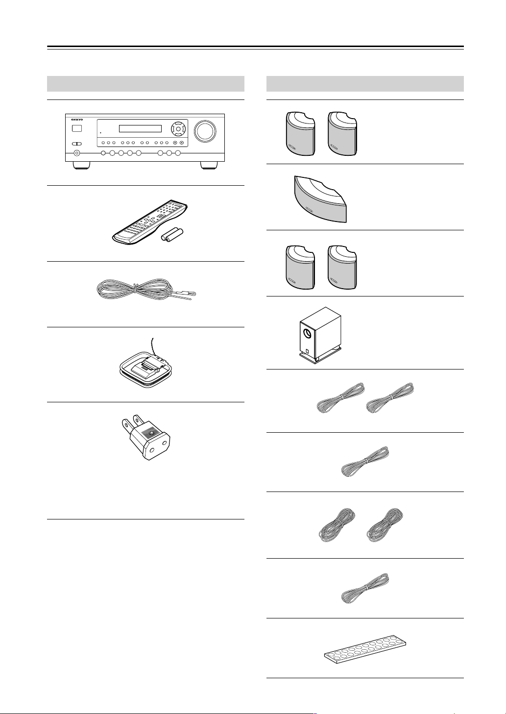
Supplied Accessories
Make sure you have the following accessories:
HT-R330
HT-R330
Remote controller & two batteries (AA/R6)
Indoor FM antenna
(Connector type varies from country to country.)
HTP-330
Front speakers
(SKF-330F L/R)
Center speaker
(SKC-330C)
Surround speakers
(SKM-330S)
Subwoofer (SKW-330)
AM loop antenna
Power-plug adapter
Only supplied in certain countries. Use this adapter if
your AC outlet does not match with the plug on the AV
receiver’s power cord. (Adapter varies from country to
country.)
* In catalogs and on packaging, the letter at the end of the
product name indicates the color. Specifications and operation are the same regardless of color.
(Red) (White)
Speaker cable for front speakers 15 ft. (4.5 m)
(Green)
Speaker cable for center speaker 10 ft. (3 m)
(Blue) (Gray)
Speaker cables for surround speakers 30 ft. (9 m)
(Purple)
Speaker cables for subwoofer 15 ft. (4.5 m)
Rubber stoppers [20]
6
Before Using the AV receiver
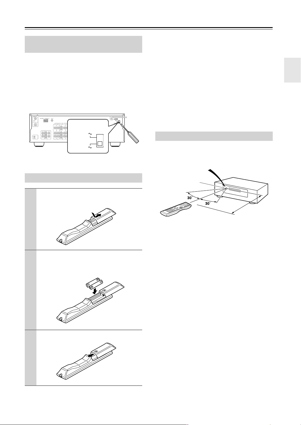
Setting the Voltage Selector (on some models)
Some models have a voltage selector switch for compatibility with power systems around the world. Before you
plug in this model, make sure that the voltage selector is
set to the correct voltage for your area. If it isn’t, use a
small screwdriver to set it as appropriate. For example, if
the voltage in your area is 120 volts, set the selector to
“120V.” If it’s between 220 and 230 volts, set it to “220230V.”
VOLTAGE
SELECTOR
120
V
220-230
V
Installing the Batteries
To open the battery compartment, press
1
the small hollow and slide open the cover.
Notes:
• The batteries should last for about six months,
although this will vary with usage.
• If the remote controller doesn’t work reliably, try
replacing the batteries.
• Don’t mix new and old batteries or different types of
batteries.
• If you intend not to use the remote controller for a long
time, remove the batteries to prevent damage from
leakage or corrosion.
• Expired batteries should be removed as soon as possible to prevent damage from leakage or corrosion.
Using the Remote Controller
To use the remote controller, point it at the AV receiver’s
remote control sensor, as shown below.
Remote control sensor
AV receiver
STANDBY indicator
Insert the two supplied batteries (AA/R6)
2
in accordance with the polarity diagram
inside the battery compartment.
Slide the cover shut.
3
Approx. 16 ft.
(5 m)
Notes:
• The remote controller may not work reliably if the AV
receiver is subjected to bright light, such as direct sunlight or inverter-type fluorescent lights. Keep this in
mind when installing.
• If another remote controller of the same type is used in
the same room, or the AV receiver is installed close to
equipment that uses infrared rays, the remote controller may not work reliably.
• Don’t put anything, such as a book, on the remote controller, because the buttons may be pressed inadvertently, thereby draining the batteries.
• The remote controller may not work reliably if the AV
receiver is installed in a rack behind colored glass
doors. Keep this in mind when installing.
• The remote controller will not work if there’s an obstacle between it and the AV receiver’s remote control
sensor.
7
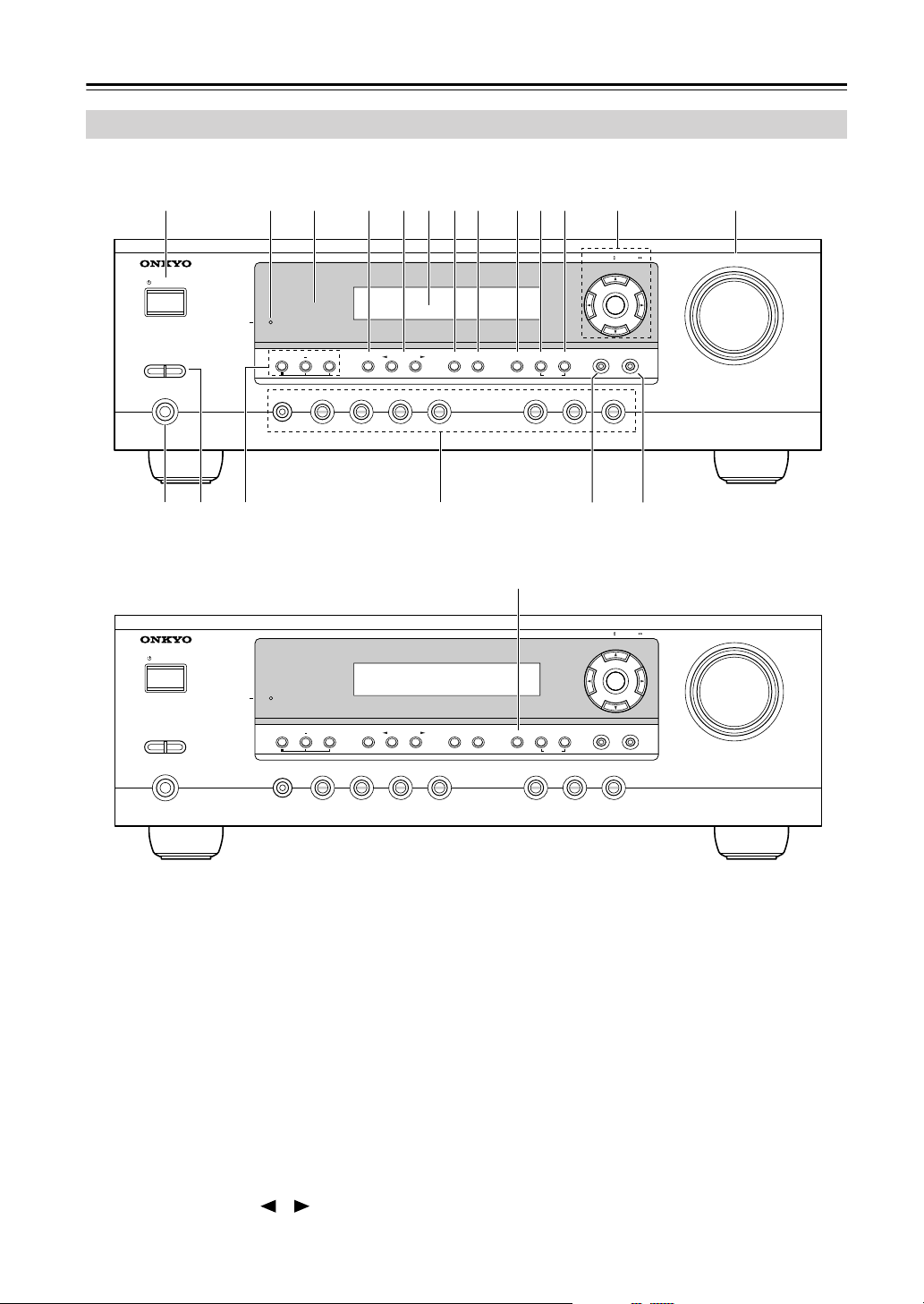
Front & Rear Panels
Front Panel
North American and Asian Models
1
STANDBY/ON
A SPEAKERS B
PHONES
European Models
STANDBY/ON
2
3 4 5 7 8 9 J K L M6
STANDBY
+
TONE
MULTl CH DVD VIDEO 1/VCR VIDEO 2 VIDEO 3 TAPE TUNER CD
STEREO
LISTENING MODE
DISPLAY
DIGITAL INPUT
DIMMER MEMORY
QN O P R S
9
STANDBY
TUNING MODE
CLEAR
TUNING / PRESET
ENTER
RETURN
TUNING / PRESET
ENTER
MASTER VOLUME
SETUP
MASTER VOLUME
A SPEAKERS B
PHONES
MULTl CH DVD VIDEO 1/VCR VIDEO 2 VIDEO 3 TAPE TUNER CD
+
TONE
STEREO
LISTENING MODE
For detailed information, see the pages in parentheses.
A STANDBY/ON button (32)
This button is used to set the AV receiver to On or
Standby.
B STANDBY indicator (32)
This indicator lights up when the AV receiver is in
Standby mode, and it flashes while a signal is being
received from the remote controller.
C Remote-control sensor (7)
This sensor receives control signals from the remote
controller.
D STEREO button (44)
This button is used to select the Stereo listening
mode.
E LISTENING MODE [ ]/[ ] buttons (44)
These buttons are used to select the listening modes.
RETURN
DISPLAY
DIGITAL INPUT
RT/PTY/TP MEMORY
TUNING MODE
CLEAR
SETUP
F Display
See “Display” on page 9.
G DISPLAY button (37)
This button is used to display various information
about the currently selected input source.
H DIGITAL INPUT button (33)
This button is used to assign the digital inputs and to
specify the format of digital input signals.
I DIMMER or RT/PTY/TP button (41, 42)
This button is used to adjust the display brightness.
On the European model, this is the RT/PTY/TP but-
ton, and it’s used with RDS (Radio Data System).
See “Using RDS (European models only)” on
page 40.
8
Front & Rear Panels—Continued
J MEMORY button (39)
This button is used when storing or deleting radio
presets.
K TUNING MODE button (38)
This button is used to select the Auto or Manual tuning mode.
L Arrow/TUNING/PRESET & ENTER buttons
When the AM or FM input source is selected, the
TUNING [ ] [ ] buttons are used to tune the
tuner, and the PRESET [ ] [ ] buttons are used
to select radio presets (see page 39). When the setup
menus are used, they work as arrow buttons and are
used to select and set items. The ENTER button is
also used with the setup menus.
M MASTER VOLUME control (36)
This control is used to adjust the volume of the AV
receiver to MIN, 1 through 79, or MAX
N PHONES jack (43)
This 1/4-inch phone jack is for connecting a standard pair of stereo headphones for private listening.
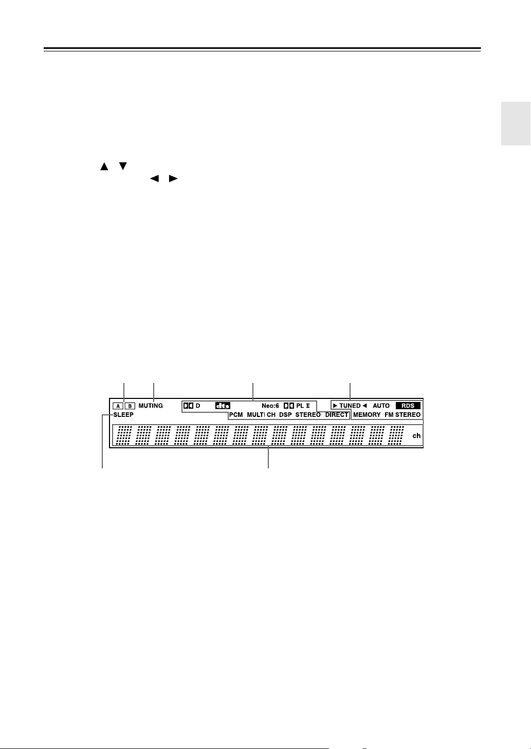
Display
O SPEAKER A & B buttons (36)
These buttons are used to turn speaker sets A and B
on or off.
P TONE, [–] & [+] buttons (42)
These buttons are used to adjust the bass and treble.
Q Input selector buttons (36)
These buttons are used to select from the following
input sources: MULTI CH, DVD, VIDEO 1/VCR,
VIDEO 2, VIDEO 3, TAPE, TUNER, or CD.
The [MULTI CH] button selects the DVD analog
multichannel input.
R RETURN button
This button is used to return to the previously displayed setup menu.
S SETUP button
This button is used to access various settings.
2134
5
For detailed information, see the pages in parentheses.
1 A & B speaker indicators (36)
Indicator A lights up when speaker set A is on. Indicator B lights up when speaker set B is on.
2 MUTING indicator (42)
This indicator flashes when the AV receiver is
muted.
3 Source/listening mode indicators (46)
These indicators show the currently selected listening mode and digital audio format.
4 Tuning indicators (38)
TUNED (38): This indicator lights up when the AV
receiver is tuned to a radio station.
AUTO (38): This indicator lights up when Auto
Tuning is selected and disappears when Manual
Tuning is selected.
6
RDS (European model only) (40): This indicator lights up when the AV Receiver is tuned to a
radio station that supports RDS (Radio Data System).
MEMORY (39): This indicator lights up when presetting radio stations.
FM STEREO (38): This indicator lights up when
the AV receiver is tuned to a stereo FM station.
5 SLEEP indicator (43)
This indicator lights up when the Sleep function has
been set.
6 Message area
This area of the display shows various information
about the currently selected source.
9
Front & Rear Panels—Continued
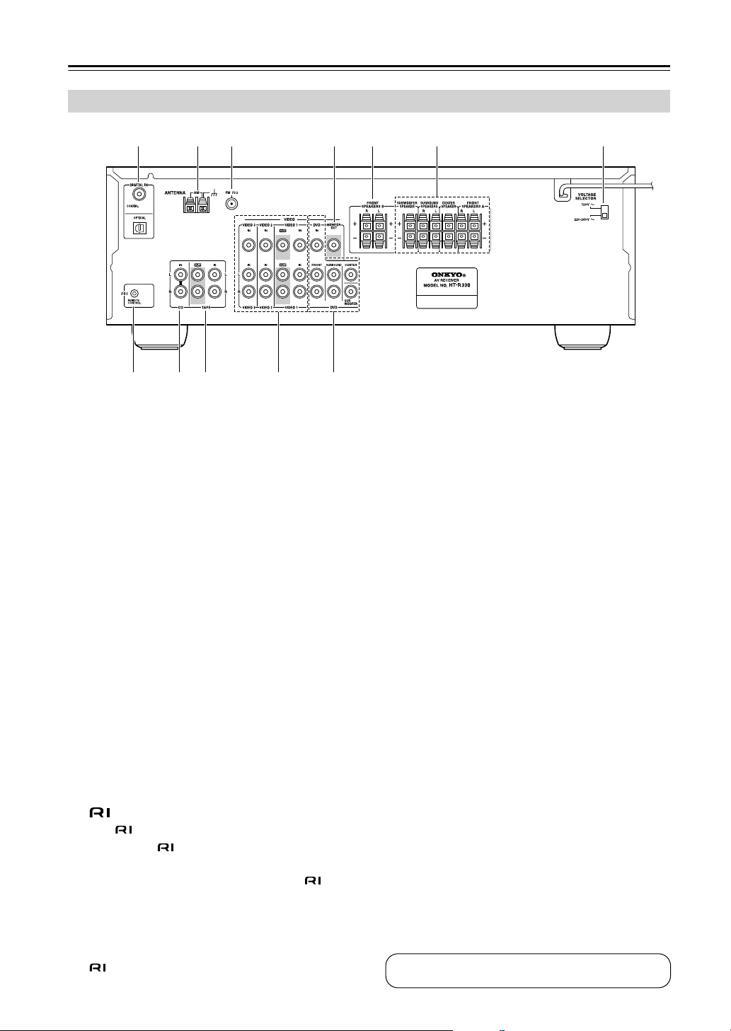
Rear Panel
1 B 3 4 5 76
8 9 J K L
A DIGITAL IN OPTICAL & COAXIAL
These optical and coaxial jacks can be used to connect a CD or DVD player and other components
with digital audio outputs.
B AM ANTENNA
These push terminals are for connecting an AM
antenna.
C FM ANTENNA
This jack is for connecting an FM antenna.
D MONITOR OUT
The composite video output should be connected to
a video input on your TV or projector.
E FRONT SPEAKERS B
These push terminals are for connecting speaker
set B.
F FRONT SPEAKERS A, SURROUND
SPEAKERS & CENTER SPEAKER
These push terminals are for connecting speaker
set A.
G VOLTAGE SELECTOR (only some models)
This voltage selector provides compatibility with
power systems around the world.
H
This (Remote Interactive) jack can be connected to the jack on another Onkyo compo-
nent. The AV receiver’s remote controller can then
be used to control that component. To use , you
must make an analog audio connection (RCA)
between the AV receiver and the other component,
even if they are connected digitally.
Note:
can only be used with Onkyo components.
I CD IN
These analog inputs can be used to connect a CD
player with analog outputs.
J TAPE IN/OUT
These analog inputs and outputs can be used to connect a cassette recorder, MiniDisc recorder, or other
recorder with analog inputs and outputs.
K VIDEO 1 IN/OUT, VIDEO 2 IN & VIDEO 3 IN
The VIDEO 1, composite video, and audio inputs
and outputs can be used to connect a VCR. The
VIDEO 2, VIDEO 3, composite video, and audio
inputs can be used to connect another video source
(e.g., cable TV, satellite TV, or a set-top box).
L DVD IN/MULTI CH INPUT
The FRONT, SURROUND, CENTER, and SUBWOOFER jacks can be used to connect a component with an analog multichannel audio output, such
as a DVD player with a 5.1-channel analog output.
The composite video input should be connected to a
video output on the DVD player.
See pages 17–31 for connection information.
10
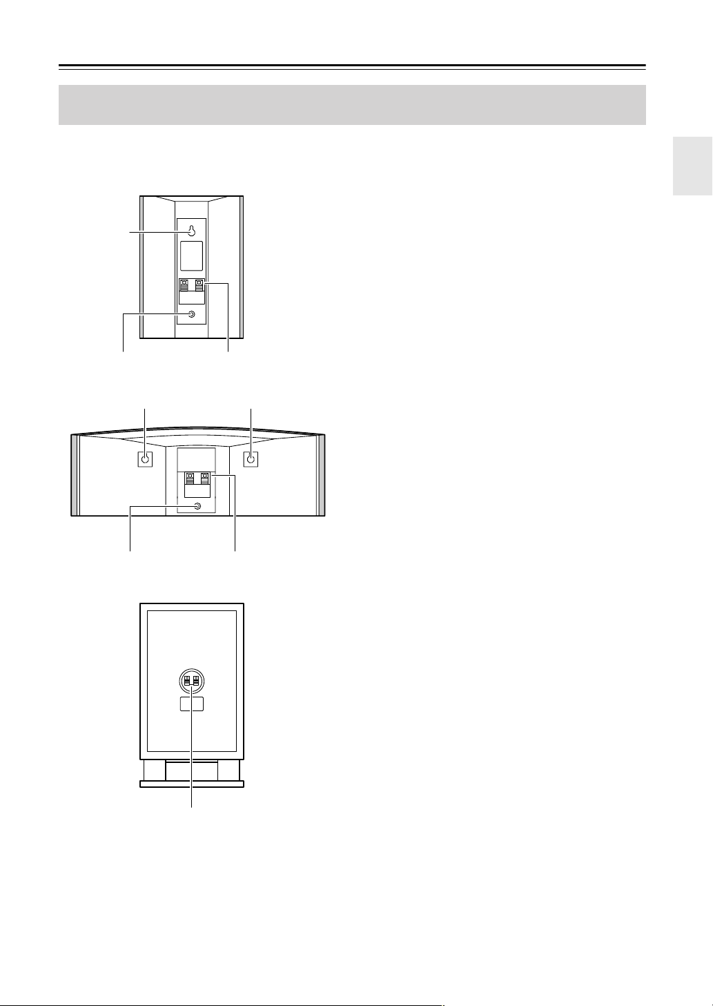
Speaker Package
Front, Center, Surround, & Subwoofer speakers (SKF-330F, SKC-330C, SKM-330S, SKW-330)
■ Rear
SKF-330F
SKM-330S
2
3
22
SKC-330C
1
A Speaker terminals
These push terminals are for connecting the speaker
to the HT-R330 with the supplied speaker cables.
The supplied speaker cables are color-coded for
easy identification. Simply connect each cable to the
same-colored positive speaker terminal.
B Keyhole slots
These keyhole slots can be used to wall-mount the
speaker. See page 19 for mounting instructions.
C Speaker mount/bracket inserts
These threaded inserts can be used to attach the
speaker to a speaker mount or bracket. See page 19
for mounting instructions.
Note:
Use commercially available machine screws to
attach the speaker to a speaker mount or bracket.
North American models require 1/4-inch screws.
Other models require M5 (5 mm) screws.
3 1
SKW-330
1
11
Remote Controller
How to Use the Remote Controller
Including the AV receiver, the remote controller can be
used to control up to six different components. The
remote controller has a specific operating mode for use
with each type of component. Modes are selected by
using the five REMOTE MODE buttons.
■ RECEIVER/TAPE Mode
In RECEIVER/TAPE mode, you can control
the AV receiver and an Onkyo cassette
recorder connected via .
■ DVD, CD, MD, & CDR Modes
With these modes, you can control an
Onkyo DVD player and CD/MD/CDR
player/recorder.
Use the REMOTE MODE buttons to select
1
a mode.
Use the buttons supported by that mode
2
to control the component.
RECEIVER mode: see page 12
DVD mode: see page 14
CD/MD/CDR mode: see page 15
TAPE mode: see page 16
Note:
Some of the remote controller operations described in
this manual may not work as expected with other components.
DVD
C
MD
CDR
D
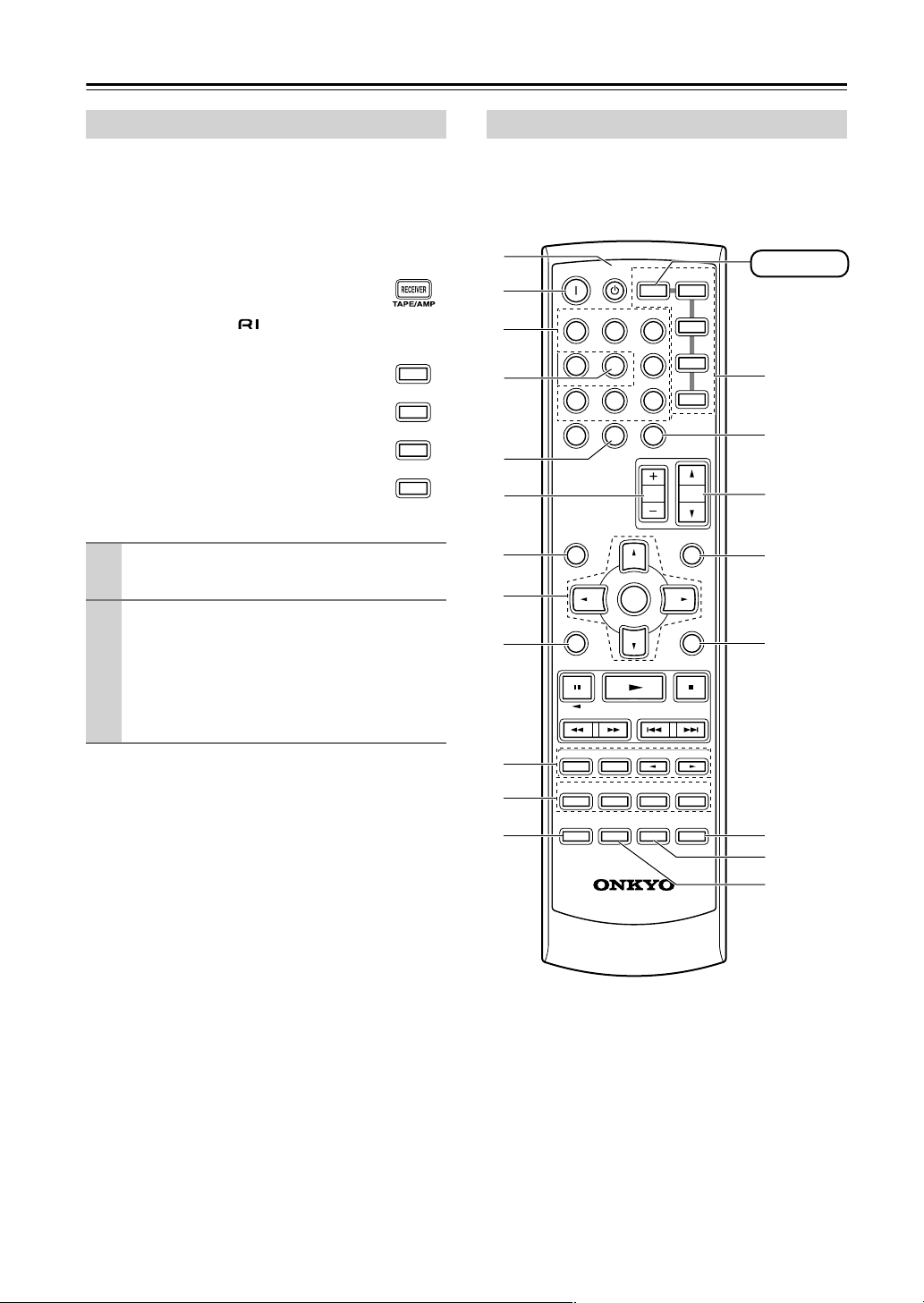
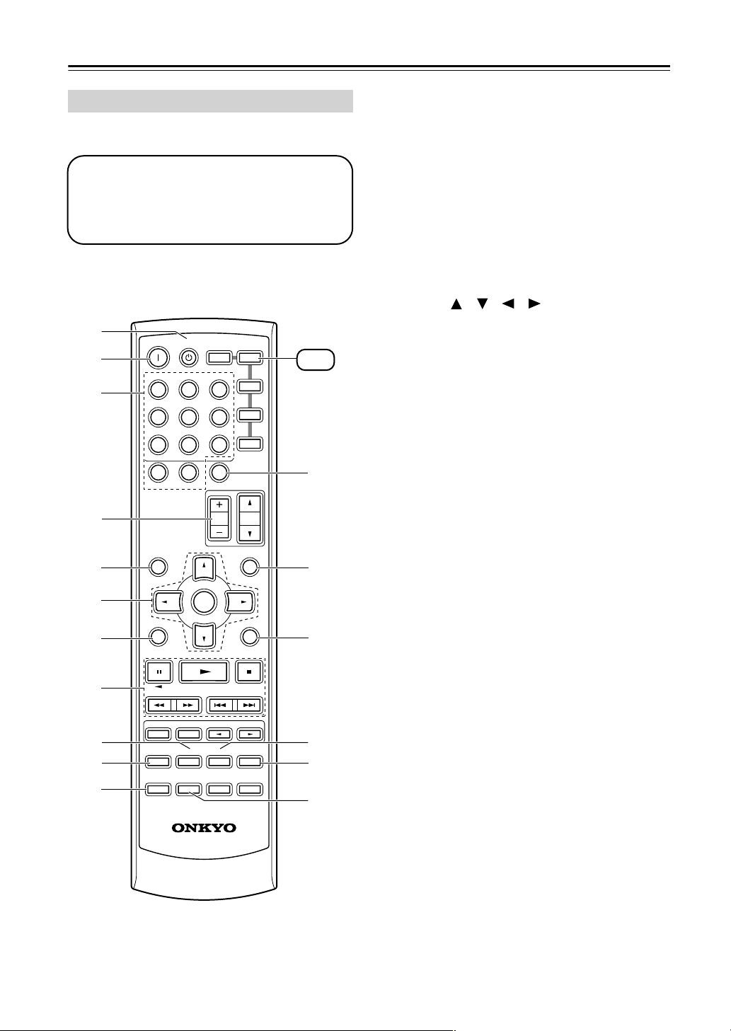
RECEIVER Mode
RECEIVER mode is used to control the AV receiver.
To set the remote controller to RECEIVER mode,
press the [RECEIVER] REMOTE MODE button.
A
B
C
D
E
F
G
H
I
J
K
L
ON STANDBY
INPUT SELECTOR
123
V1V2V
456
789
+
10
--/---
SP A / B
STEREO
AUDIO REPEAT
TEST TONE
DISPLAY
RECEIVER
TAPE/AMP
MULTI CH
0
DIMMER SLEEP
ENTER
LISTENING MODE
SURROUND
SUBTITLE
RANDOM
CH SEL
LEVEL
PLAY MODE
L NIGHT
OR-EQ
REMOTE MODE
DVD
C D
3
MD
DVD
CDR
C DTAPE TUNER
CLR
CH
VOL
DISC
MENUTOP MENU
MUTING
SETUPRETURN
-
LEVEL
CINE FLTR
+
RECEIVER
M
N
O
P
Q
R
S
-
606S
RC
T
12

Remote Controller—Continued
For detailed information, see the pages in parentheses.
A STANDBY button (32)
This button is used to set the AV receiver to
Standby.
B ON button (32)
This button is used to turn on the AV receiver.
C INPUT SELECTOR buttons (36)
These buttons are used to select the input sources.
D MULTI CH button (37)
This button is used to select the multichannel DVD
input.
E DIMMER button (42)
This button is used to adjust the display brightness.
F CH +/– button (39)
This button is used to select radio presets.
G SP A/B button (36)
This button is used to turn speaker sets A and B on
or off.
H Arrow [ ]/[ ]/[ ]/[ ] & ENTER buttons
These buttons are used to select and adjust settings.
I RETURN button
This button is used to return to the previous display
when changing settings.
J LISTENING MODE buttons (44)
These buttons can be used to select listening modes
regardless of the currently selected remote controller mode.
STEREO button
This button selects the Stereo listening mode.
SURROUND button
This button selects the Dolby and DTS listening
modes.
[ ]/[ ] buttons
These buttons can be used to select any of the available listening modes.
K TEST TONE, CH SEL, LEVEL- & LEVEL+
buttons (35)
These buttons are used to adjust the level of each
speaker.
L DISPLAY button (37)
This button is used to display various information
about the currently selected input source.
M REMOTE MODE buttons (12)
These buttons are used to select the remote controller modes. When you press a button on the remote
controller, the REMOTE MODE button for the currently selected mode lights up.
N SLEEP button (43)
This button is used to set the Sleep function.
O VOL [ ]/[ ] button (36)
This button can be used to adjust the volume of the
AV receiver regardless of the currently selected
remote controller mode.
P MUTING button (42)
This button is used to mute the AV receiver.
Q SETUP button
This button is used to access various settings.
R CINE FLTR button (48)
This button is used to set the CinemaFILTER function.
S L NIGHT button (48)
This button is used to set the Late Night function.
T OR-EQ button (42)
This button is used to turn on the OptiResponse
equalizer, which optimizes performance when the
HT-R330 is used with the speakers included in the
HTP-330 Home Theater Speaker Package. When
the OptiResponse equalizer is on, you can enjoy a
powerful sound with movies or music with small
volume.
13
Remote Controller—Continued
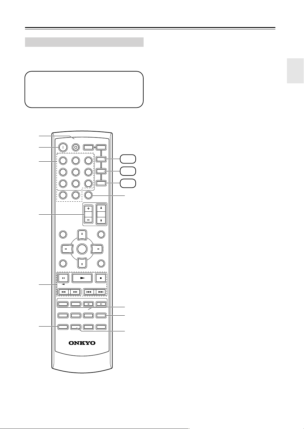
DVD Mode
To set the remote controller to DVD mode, press the
[DVD] REMOTE MODE button.
Before selecting DVD mode and starting playback, you should press the [RECEIVER] mode
button followed by the [DVD] INPUT SELECTOR button to select the DVD player as the
input source.
A
B
C
D
E
F
G
ON STANDBY
INPUT SELECTOR
123
V1V2V
456
789
+
10
--/---
SP A / B
TAPE/AMP
MULTI CH
0
DIMMER SLEEP
ENTER
REMOTE MODE
RECEIVER
DVD
C DTAPE TUNER
CLR
CH
DISC
DVD
C D
3
MD
CDR
DVD
L
VOL
MENUTOP MENU
MUTING
SETUPRETURN
M
N
H
LISTENING MODE
SURROUND
I
J
K
STEREO
SUBTITLE
AUDIO REPEAT
TEST TONE
DISPLAY
CH SEL
PLAY MODE
OR-EQ
RC
RANDOM
LEVEL
L NIGHT
-
606S
-
LEVEL
CINE FLTR
+
O
P
Q
A STANDBY button
This button sets the DVD player to Standby.
B ON button
This button is used to turn on the DVD player.
C Number buttons
These buttons are used to enter title, chapter, and
track numbers and to enter times for locating specific points in time.
D DISC +/– button
This button selects discs on a DVD changer.
E TOP MENU button
This button is used to select a DVD’s top menu.
F Arrow [ ]/[ ]/[ ]/[ ] & ENTER buttons
These buttons are used to navigate DVD menus and
the DVD player’s onscreen setup menus.
G RETURN button
This button is used to exit the DVD player’s
onscreen setup menu and to restart menu playback.
H Playback buttons
From left to right: Pause, Play, Stop, Fast Reverse,
Fast Forward, Previous, and Next.
I SUBTITLE button
This button is used to select subtitles.
J AUDIO button
This button selects foreign language soundtracks
and audio formats (e.g., Dolby Digital or DTS).
K DISPLAY button
This button is used to display information about the
current disc, title, chapter, or track on the DVD
player’s display, including the elapsed time, remaining time, total time, and so on.
L CLR button
This button is used to cancel functions and to clear
entered numbers.
M MENU button
This button is used to display a DVD’s menu.
N SETUP button
This button is used to access the DVD player’s
onscreen setup menus.
O RANDOM button
This button is used with the random playback function.
P REPEAT button
This button is used to set the repeat playback functions.
Q PLAY MODE button
This button is used to select play modes on a component with selectable play modes.
14
Remote Controller—Continued
CD, MD, & CDR Mode
To set the remote controller to CD, MD, or CDR
mode, press the [CD], [MD], or [CDR] REMOTE
MODE button.
Before selecting a mode and starting playback,
you should press the [RECEIVER] mode button followed by the [CD] or [TAPE] INPUT
SELECTOR button to select the CD player,
MiniDisc, or CD recorder as the input source.
A
B
C
D
ON STANDBY
INPUT SELECTOR
123
V1V2V
456
789
+
10
--/---
SP A / B
RECEIVER
TAPE/AMP
MULTI CH
0
DIMMER SLEEP
ENTER
REMOTE MODE
3
DVD
C DTAPE TUNER
CLR
CH
DISC
DVD
C D
MD
CDR
VOL
MENUTOP MENU
MUTING
CD
MD
CDR
G
A STANDBY button
This button sets the CD player or MD/CD recorder
to Standby.
B ON button
This button is used to set the CD player or MD/CD
recorder to On or Standby.
C Number buttons
These buttons are used to enter track numbers and
to enter times for locating specific points in time.
D DISC +/– button
This button selects discs on a CD changer.
E Playback buttons
From left to right: Pause, Play, Stop, Fast Reverse,
Fast Forward, Previous and Next.
F DISPLAY button
This button is used to display information about the
current disc or track on the CD player or MD/CD
recorder’s display, including the elapsed time,
remaining time, total time, and so on.
G CLR button
This button is used to cancel functions and to clear
entered numbers.
H RANDOM button
This button is used with the random playback function.
I REPEAT button
This button is used to set the repeat playback functions.
J PLAY MODE button
This button is used to select play modes on a component with selectable play modes.
E
F
SETUPRETURN
LISTENING MODE
SURROUND
STEREO
SUBTITLE
AUDIO REPEAT
TEST TONE
DISPLAY
CH SEL
PLAY MODE
OR-EQ
RC
RANDOM
LEVEL
L NIGHT
-
606S
-
LEVEL
CINE FLTR
8
+
9
J
15
Remote Controller—Continued
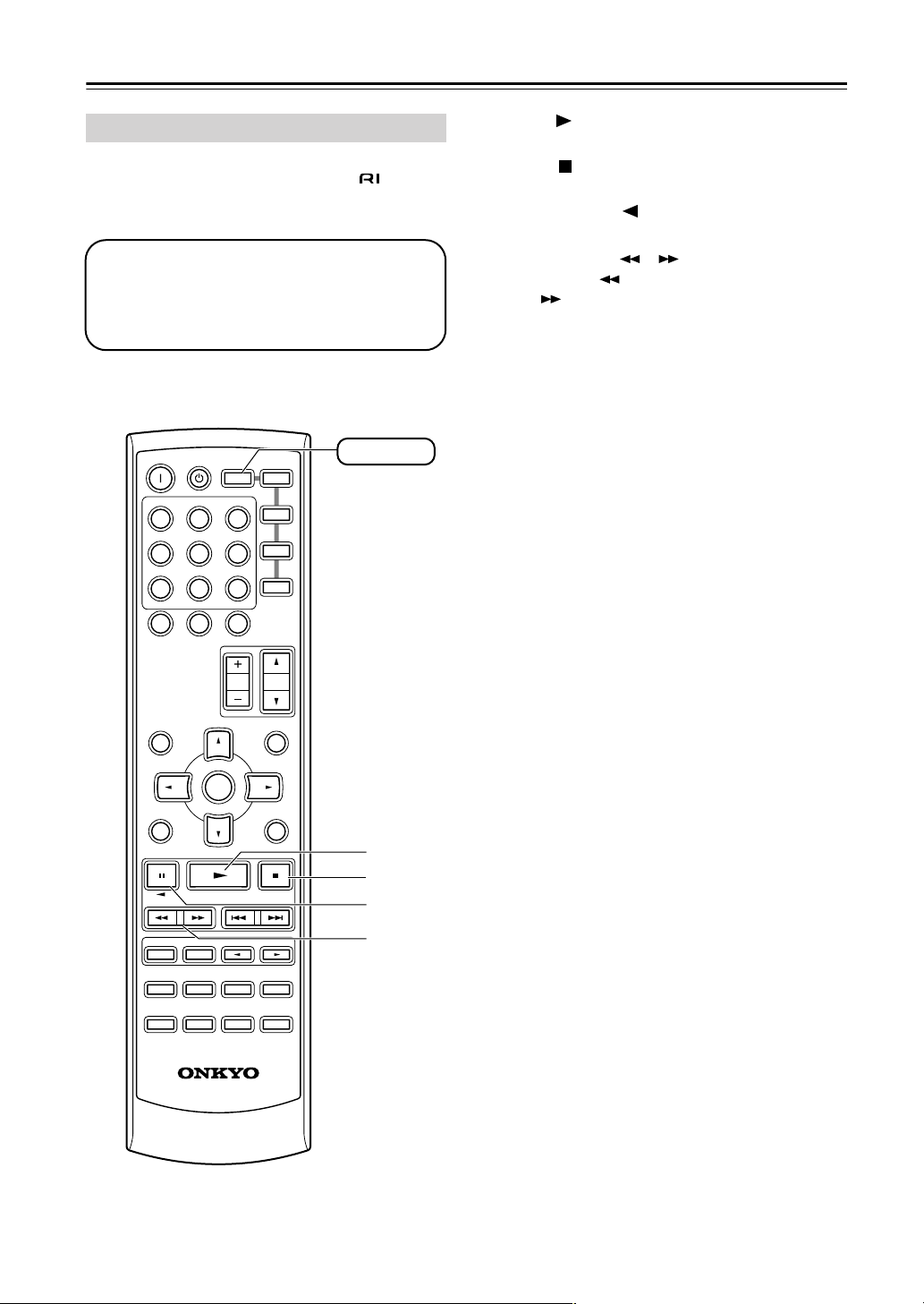
TAPE Mode
TAPE mode is used to control an Onkyo cassette
recorder connected to the AV receiver via .
To set the remote controller to TAPE mode, press the
[RECEIVER] REMOTE MODE button.
Before selecting TAPE mode and starting playback, you should press the [RECEIVER]
REMOTE MODE button followed by the [TAPE]
INPUT SELECTOR button to select your cassette recorder as the input source.
For twin cassette decks, only deck B can be controlled.
ON STANDBY
INPUT SELECTOR
123
V1V2V
456
789
+
10
--/---
REMOTE MODE
RECEIVER
TAPE/AMP
MULTI CH
0
DIMMER SLEEP
3
DVD
C DTAPE TUNER
CLR
DVD
C D
MD
CDR
RECEIVER
A Play [ ] button
This button is used to start playback.
B Stop [ ] button
This button is used to stop playback.
C Reverse Play [ ] button
This button is used to start reverse playback.
D Rewind & FF [ ]/[ ] buttons
The Rewind [ ] button is used to start rewind. The
FF [ ] button is used to start fast forward.
CH
VOL
DISC
MENUTOP MENU
RANDOM
LEVEL
L NIGHT
-
606S
MUTING
SETUPRETURN
-
LEVEL
CINE FLTR
SP A / B
ENTER
LISTENING MODE
SURROUND
STEREO
SUBTITLE
AUDIO REPEAT
TEST TONE
CH SEL
PLAY MODE
DISPLAY
OR-EQ
RC
A
B
C
D
+
16
Connecting Your Speakers
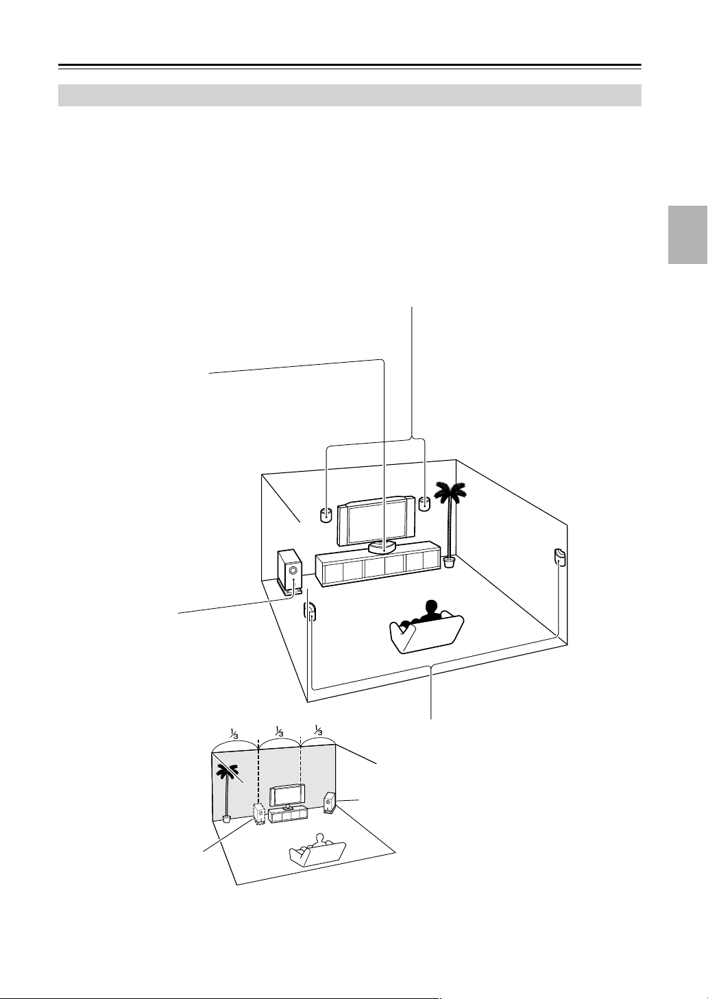
Enjoying Home Theater
You can use two sets of speakers with the AV receiver: speaker set A and speaker set B.
Speaker set A should be installed in your main listening room and can be used with Dolby Digital and DTS surround
material. Each speaker must be positioned at a specific location in your listening room to get the best from surround
sound material. The following illustration shows the best positions for your surround-sound speakers. When speaker set
B is turned on, speaker set A is reduced to 2.1-channel playback. If the multichannel DVD input is selected, and speaker
set B is turned on, speaker set A is reduced to 2-channel playback.
Speaker set B can be installed in another room. Speakers can be positioned in the standard position for stereo speakers
or however you like.
Front left and right speakers (SKF-330F L/R)
These output the overall sound. Their role in a home theater is to provide a solid anchor for
the sound image. They should be positioned facing the listener at about ear level, and equidistant from the TV. Angle them inward so as to create a triangle, with the listener at the apex.
Center speaker (SKC-330C)
This speaker enhances the front left
and right speakers, making sound
movements distinct and providing a
full sound image. In movies it’s used
mainly for dialog.
Position it close to your TV (preferably
on top) facing forward at about ear
level, or at the same height as the
front left and right speakers.
Subwoofer (SKW-330)
The subwoofer handles the bass sounds of
the LFE (Low-Frequency Effects) channel.
The volume and quality of the bass output
from your subwoofer will depend on its position, the shape of your listening room, and
your listening position. In general, a good
bass sound can be obtained by installing the
subwoofer in a front corner,
or at one-third the width of
the wall, as shown.
Corner
1/3 wall
length
Surround left and right speakers
(SKM-330S L/R)
These speakers are used for precise sound
positioning and to add realistic ambience.
Position them at the sides of the listener, or
slightly behind, about 2–3 feet (60–100 cm)
above ear level. Ideally they should be equidistant from the listener.
To get the very best from your surround-sound system, you should also specify the distance between the listener and
each individual speaker so that the sound from each speaker arrives at the listener’s ears at the same time (see page 51).
In addition, you should set the level of each individual speaker to achieve an equal balance (see page 51.)
17
Connecting Your Speakers—Continued
Speaker Connection Precautions Connecting Speaker
Read the following before connecting your speakers:
•You can connect speakers with an impedance of
8 ohms or higher. If you use speakers with a lower
impedance, and use the amplifier at high volume levels for a long period of time, the built-in protection
circuit may be activated.
• Disconnect the power cord from the wall outlet before
making any connections.
•Pay close attention to speaker wiring polarity. In other
words, connect positive (+) terminals to only positive
(+) terminals, and negative (–) terminals to only negative (–) terminals. If you get them the wrong way
around, the sound will be out of phase and will sound
unnatural.
• Unnecessarily long, or very thin speaker cables may
affect the sound quality and should be avoided.
• Be careful not to short the
positive and negative wires.
Doing so may damage the AV
receiver.
• Don’t connect more than one
cable to each speaker terminal. Doing so may damage the
AV receiver.
• Don’t connect one speaker to several terminals.
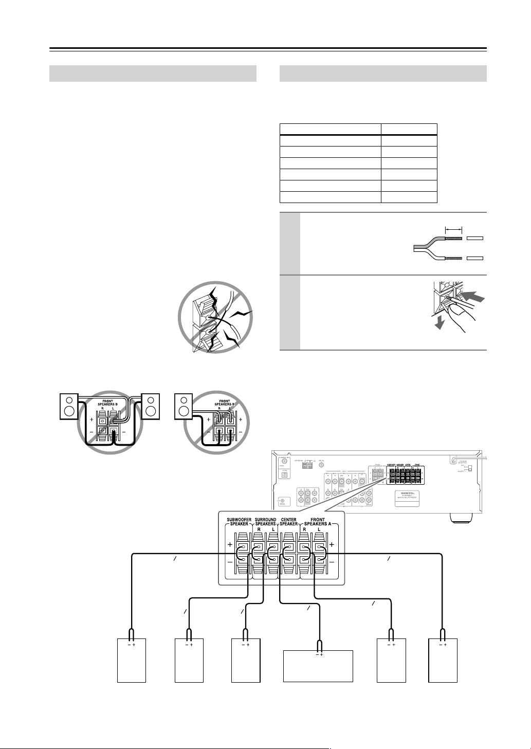
The AV receiver’s positive (+) speaker terminals are
color-coded for ease of identification. (The negative (–)
speaker terminals are all black.)
Speaker terminal Color
Front left White
Front right Red
Center Green
Surround left Blue
Surround right Gray
Subwoofer Purple
Strip 3/8" (10 mm) of insu-
1
lation from the ends of the
speaker cables. (Supplied
speaker cables are already
stripped.)
While pressing the lever, insert
2
the wire into the hole, and then
release the lever.
Make sure that the terminals are
gripping the bare wires, not the
insulation.
Note:
When speaker set B is turned on, speaker set A is reduced
to 2.1-channel playback.
3/8" (10 mm)
Subwoofer
Purple
Gray
right
speaker
Blue
Surround
left
speaker
The following illustration shows which speaker should
be connected to each pair of terminals.
White
Green
Center speakerSurround
Red
Front right
speaker
Front left
speaker
18
 Loading...