

Page 1

Contents
AV RECEIVER
HT-R592
Instruction Manual
Safety Information and Introduction ............2
Table of Contents...........................................5
Connections .................................................11
Turning On & Basic Operations..................18
Advanced Operations ..................................36
Controlling Other Components...................51
Appendix.......................................................57
Speaker Package
Remote Control Codes
E
n
Page 2
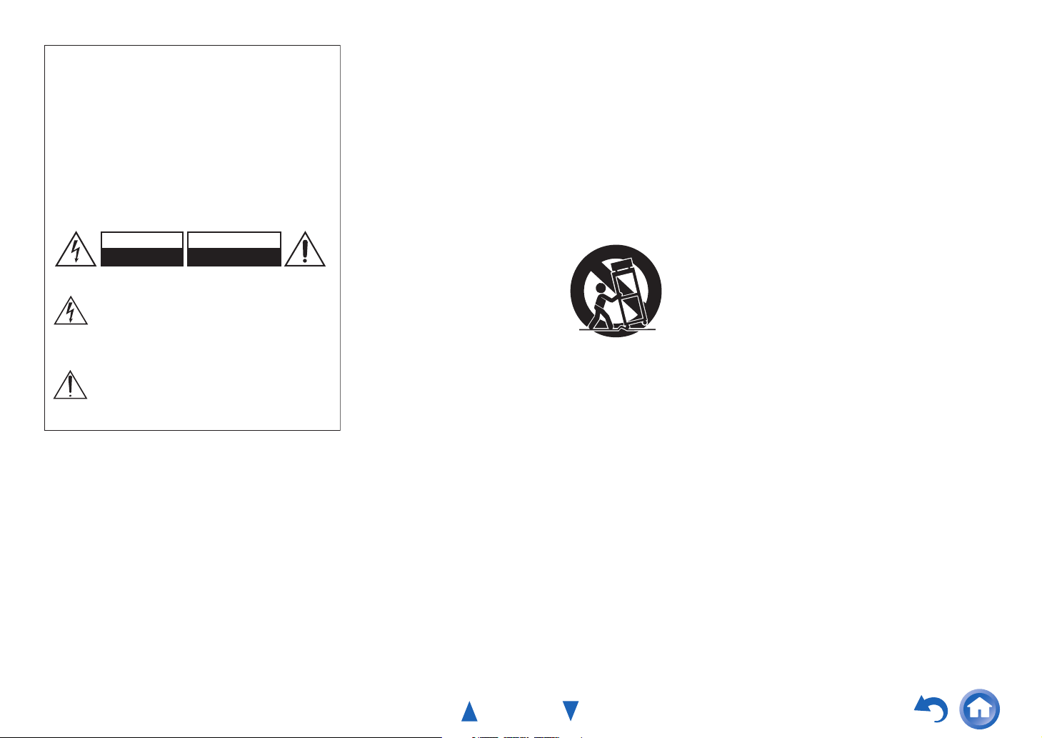
WARNING:
G
TO REDUCE THE RISK OF FIRE OR ELECTRIC SHOCK,
DO NOT EXPOSE THIS APPARATUS TO RAIN OR
MOISTURE.
CAUTION:
TO REDUCE THE RISK OF ELECTRIC SHOCK, DO NOT
REMOVE COVER (OR BACK). NO USER-SERVICEABLE
PARTS INSIDE. REFER SERVICING TO QUALIFIED
SERVICE PERSONNEL.
WARNING
RISK OF ELECTRIC SHOCK
DO NOT OPEN
The lightning flash with arrowhead symbol, within an
equilateral triangle, is intended to alert the user to the
presence of uninsulated “dangerous voltage” within
the product’s enclosure that may be of sufficient
magnitude to constitute a risk of electric shock to
persons.
The exclamation point within an equilateral triangle is
intended to alert the user to the presence of important
operating and maintenance (servicing) instructions in
the literature accompanying the appliance.
AVIS
RISQUE DE CHOC ELECTRIQUE
NE PAS OUVRIR
Important Safety Instructions
1. Read these instructions.
2. Keep these instructions.
3. Heed all warnings.
4. Follow all instructions.
5. Do not use this apparatus near water.
6. Clean only with dry cloth.
7. Do not block any ventilation openings. Install in
accordance with the manufacturer’s instructions.
8. Do not install near any heat sources such as radiators,
heat registers, stoves, or other apparatus (including
amplifiers) that produce heat.
9. Do not defeat the safety purpose of the polarized or
grounding-type plug. A polarized plug has two blades
with one wider than the other. A grounding type plug
has two blades and a third grounding prong. The wide
blade or the third prong are provided for your safety. If
the provided plug does not fit into your outlet, consult
an electrician for replacement of the obsolete outlet.
10. Protect the power cord from being walked on or
pinched particularly at plugs, convenience receptacles,
and the point where they exit from the apparatus.
11. Only use attachments/accessories specified by the
manufacturer.
12. Use only with the cart, stand,
PORTABLE CART WARNIN
tripod, bracket, or table
specified by the manufacturer,
or sold with the apparatus.
When a cart is used, use
caution when moving the
cart/apparatus combination to
avoid injury from tip-over.
S3125A
13. Unplug this apparatus during lightning storms or when
unused for long periods of time.
14. Refer all servicing to qualified service personnel.
Servicing is required when the apparatus has been
damaged in any way, such as power-supply cord or
plug is damaged, liquid has been spilled or objects
have fallen into the apparatus, the apparatus has been
exposed to rain or moisture, does not operate normally,
or has been dropped.
15. Damage Requiring Service
Unplug the apparatus from the wall outlet and refer
servicing to qualified service personnel under the
following conditions:
A. When the power-supply cord or plug is damaged,
B. If liquid has been spilled, or objects have fallen
into the apparatus,
C. If the apparatus has been exposed to rain or water,
Safety Information and Introduction
D. If the apparatus does not operate normally by
following the operating instructions. Adjust only
those controls that are covered by the operating
instructions as an improper adjustment of other
controls may result in damage and will often
require extensive work by a qualified technician to
restore the apparatus to its normal operation,
E. If the apparatus has been dropped or damaged in
any way, and
F. When the apparatus exhibits a distinct change in
performance this indicates a need for service.
16. Object and Liquid Entry
Never push objects of any kind into the apparatus
through openings as they may touch dangerous voltage
points or short-out parts that could result in a fire or
electric shock.
The apparatus shall not be exposed to dripping or
splashing and no objects filled with liquids, such as
vases shall be placed on the apparatus.
Don’t put candles or other burning objects on top of
this unit.
17. Batteries
Always consider the environmental issues and follow
local regulations when disposing of batteries.
18. If you install the apparatus in a built-in installation,
such as a bookcase or rack, ensure that there is
adequate ventilation.
Leave 20 cm (8") of free space at the top and sides and
10 cm (4") at the rear. The rear edge of the shelf or
board above the apparatus shall be set 10 cm (4") away
from the rear panel or wall, creating a flue-like gap for
warm air to escape.
The temperature protection operates if the apparatus
attain an abnormal high temperature.
The apparatus cannot operate until it has cooled down.
En-2
Page 3

Precautions
1. Recording Copyright—Unless it’s for personal use
only, recording copyrighted material is illegal without
the permission of the copyright holder.
2. AC Fuse—The AC fuse inside the unit is not userserviceable. If you cannot turn on the unit, contact your
Onkyo dealer.
3. Care—Occasionally you should dust the unit all over
with a soft cloth. For stubborn stains, use a soft cloth
dampened with a weak solution of mild detergent and
water. Dry the unit immediately afterwards with a
clean cloth. Don’t use abrasive cloths, thinners,
alcohol, or other chemical solvents, because they may
damage the finish or remove the panel lettering.
4. Power
WARNING
BEFORE PLUGGING IN THE UNIT FOR THE
FIRST TIME, READ THE FOLLOWING SECTION
CAREFULLY.
AC outlet voltages vary from country to country. Make
sure that the voltage in your area meets the voltage
requirements printed on the unit’s rear panel (e.g., AC
230 V, 50 Hz or AC 120 V, 60 Hz).
The power cord plug is used to disconnect this unit
from the AC power source. Make sure that the plug is
readily operable (easily accessible) at all times.
For models with [POWER] button, or with both
[POWER] and [ON/STANDBY] buttons:
Pressing the [POWER] button to select OFF mode
does not fully disconnect from the mains. If you do not
intend to use the unit for an extended period, remove
the power cord from the AC outlet.
For models with [ON/STANDBY] button only:
Pressing the [ON/STANDBY] button to select
Standby mode does not fully disconnect from the
mains. If you do not intend to use the unit for an
extended period, remove the power cord from the AC
outlet.
5. Preventing Hearing Loss
Caution
Excessive sound pressure from earphones and
headphones can cause hearing loss.
6. Batteries and Heat Exposure
Warning
Batteries (battery pack or batteries installed) shall not
be exposed to excessive heat as sunshine, fire or the
like.
7. Never Touch this Unit with Wet Hands—Never
handle this unit or its power cord while your hands are
wet or damp. If water or any other liquid gets inside
this unit, have it checked by your Onkyo dealer.
8. Handling Notes
• If you need to transport this unit, use the original
packaging to pack it how it was when you originally
bought it.
• Do not leave rubber or plastic items on this unit for a
long time, because they may leave marks on the
case.
• This unit’s top and rear panels may get warm after
prolonged use. This is normal.
• If you do not use this unit for a long time, it may not
work properly the next time you turn it on, so be sure
to use it occasionally.
For U.S. models
FCC Information for User
CAUTION:
The user changes or modifications not expressly approved
by the party responsible for compliance could void the
user’s authority to operate the equipment.
NOTE:
This equipment has been tested and found to comply with
the limits for a Class B digital device, pursuant to Part 15
of the FCC Rules. These limits are designed to provide
reasonable protection against harmful interference in a
residential installation.
Safety Information and Introduction
This equipment generates, uses and can radiate radio
frequency energy and, if not installed and used in
accordance with the instructions, may cause harmful
interference to radio communications. However, there is no
guarantee that interference will not occur in a particular
installation. If this equipment does cause harmful
interference to radio or television reception, which can be
determined by turning the equipment off and on, the user is
encouraged to try to correct the interference by one or more
of the following measures:
• Reorient or relocate the receiving antenna.
• Increase the separation between the equipment and
receiver.
• Connect the equipment into an outlet on a circuit different
from that to which the receiver is connected.
• Consult the dealer or an experienced radio/TV technician
for help.
For Canadian Models
NOTE: THIS CLASS B DIGITAL APPARATUS
COMPLIES WITH CANADIAN ICES-003.
For models having a power cord with a polarized plug:
CAUTION: TO PREVENT ELECTRIC SHOCK,
MATCH WIDE BLADE OF PLUG TO WIDE SLOT,
FULLY INSERT.
Modèle pour les Canadien
REMARQUE: CET APPAREIL NUMÉRIQUE DE LA
CLASSE B EST CONFORME À LA NORME NMB-003
DU CANADA.
Sur les modèles dont la fiche est polarisée:
ATTENTION: POUR ÉVITER LES CHOCS
ÉLECTRIQUES, INTRODUIRE LA LAME LA PLUS
LARGE DE LA FICHE DANS LA BORNE
CORRESPONDANTE DE LA PRISE ET POUSSER
JUSQU’AU FOND.
En-3
Page 4

Supplied Accessories
Make sure you have the following accessories:
Indoor FM antenna (➔ page 17)
AM loop antenna (➔ page 17)
Power cord (Brazilian
(➔ page 17)
Speaker cable labels (
(➔ page 12)
Speaker setup microphone (➔ page 26)
Remote controller (RC-863M) and two batteries (AA/R6)
Quick Start Guide
and Taiwanese models)
Taiwanese models)
■ Installing the batteries
Batteries (AA/R6)
Safety Information and Introduction
■ Aiming the remote controller
To use the remote controller, point it at the AV receiver’s
remote control sensor, as shown below.
Remote control sensor
AV receiver
Approx. 16 ft. (5 m)
*
In catalogs and on packaging, the letter at the end of the product
name indicates the color. Specifications and operations are the
same regardless of color.
Note
• If the remote controller doesn’t work reliably, try replacing the
batteries.
• Don’t mix new and old batteries or different types of batteries.
• If you intend not to use the remote controller for a long time,
remove the batteries to prevent damage from leakage or
corrosion.
• Remove expired batteries as soon as possible to prevent damage
from leakage or corrosion.
Thank you for purchasing an Onkyo AV Receiver.
Please read this manual thoroughly before making
connections and plugging in the unit.
Following the instructions in this manual will
enable you to obtain optimum performance and
listening enjoyment from your new AV Receiver.
Please retain this manual for future reference.
En-4
Page 5
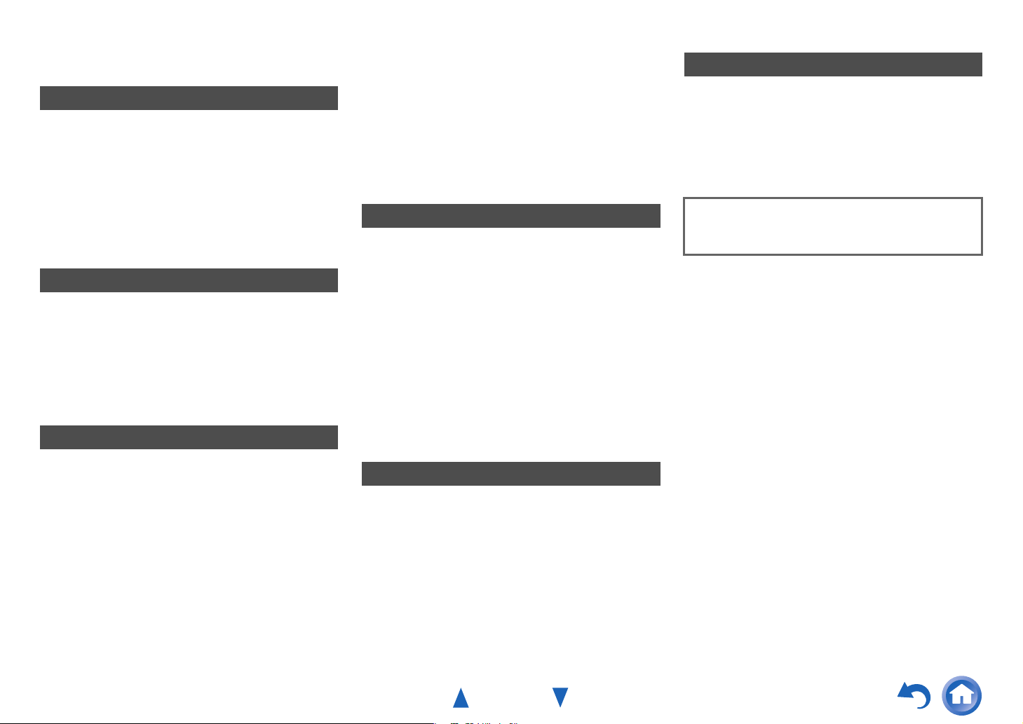
Table of Contents
Safety Information and Introduction
Important Safety Instructions ......................................2
Precautions ...................................................................3
Supplied Accessories...................................................4
Table of Contents..........................................................5
Features .........................................................................6
Front & Rear Panels......................................................7
Front Panel..................................................................7
Display ........................................................................8
Rear Panel ..................................................................9
Remote Controller.......................................................10
Controlling the AV Receiver ......................................10
Connections
Connecting the AV Receiver......................................11
Connecting Your Speakers .......................................11
About AV Connections..............................................13
Connecting Components with HDMI .........................14
Connecting Your Components ..................................15
Connecting Onkyo RI Components...........................16
Connecting a Recording Component ........................16
Connecting the Antennas..........................................17
Connecting the Power Cord ......................................17
Turning On & Basic Operations
Turning On/Off the AV Receiver ................................18
Turning On ................................................................18
Turning Off ................................................................18
Playback ......................................................................19
Playing the Connected Component ..........................19
Controlling Contents of USB Devices .......................20
Understanding Icons on the Display .........................21
Playing an iPod/iPhone via USB ...............................21
Playing a USB Device ...............................................22
Listening to AM/FM Radio.........................................23
Using Basic Functions ............................................... 26
Using the Automatic Speaker Setup......................... 26
Using the Listening Modes .......................................29
Using the Home Menu .............................................. 34
Setting the Display Brightness.................................. 34
Using the Sleep Timer ..............................................34
Muting the AV Receiver ............................................ 34
Displaying Source Information.................................. 35
Changing the Input Display....................................... 35
Using the Music Optimizer........................................ 35
Using Headphones ...................................................35
Recording .................................................................35
Advanced Operations
On-screen Setup......................................................... 36
Common Procedures in Setup Menu........................ 36
Setup menu items..................................................... 37
1. HDMI Input............................................................ 38
2. Component (Component Video Input) .................. 38
3. Digital Audio (Digital Audio Input) ......................... 39
4. Sp Config (Speaker Configuration)....................... 39
5. Sp Distance (Speaker Distance)........................... 40
6. Level Cal (Level Calibration)................................. 41
7. Audio Adjust.......................................................... 41
8. Source Setup ........................................................ 42
9. Hardware ..............................................................45
10. HDMI Setup ........................................................46
Using the Audio Settings ..........................................47
Zone 2 ..........................................................................49
Making Zone 2 Connections ..................................... 49
Controlling Zone 2 Components ............................... 50
Controlling Other Components
iPod/iPhone Playback via Onkyo Dock ....................51
Using the Onkyo Dock .............................................. 51
Controlling Your iPod/iPhone.................................... 52
Controlling Other Components ................................. 53
Preprogrammed Remote Control Codes ..................53
Entering Remote Control Codes............................... 53
Remapping Colored Buttons..................................... 53
Remote Control Codes
for Onkyo Components Connected via RI.............. 54
Resetting the REMOTE MODE Buttons ...................54
Resetting the Remote Controller ..............................54
Controlling Other Components .................................54
Safety Information and Introduction
Appendix
Troubleshooting ......................................................... 57
Connection Tips and Video Signal Path .................. 62
Using an RIHD-compatible TV, Player,
or Recorder .............................................................. 63
About HDMI................................................................. 65
USB Features.............................................................. 66
License and Trademark Information ........................ 67
Specifications ............................................................. 68
To reset the AV receiver to its factory defaults, turn it
on and, while holding down VCR/DVR, press
8ON/STANDBY (➔ page 57).
En-5
Page 6

Safety Information and Introduction
Features
Amplifier
• 80 Watts/Channel @ 8 ohms (FTC)
• 130 Watts/Channel @ 6 ohms (IEC)
• 160 Watts/Channel @ 6 ohms (JEITA)
• Optimum Gain Volume Circuitry
• H.C.P.S. (High Current Power Supply) Massive High
Power Transformer
Processing
• HDMI (Audio Return Channel, 3D, DeepColor,
x.v.Color, Lip Sync, DTS-HD Master Audio, DTS-HD
High Resolution Audio, Dolby TrueHD, Dolby Digital
Plus, DSD and Multi-CH PCM)
• Dolby Pro Logic IIz
• Non-Scaling Configuration
• A-Form Listening Mode Memory
•Direct Mode
• Music Optimizer for Compressed Digital Music files
• 192 kHz/24-bit D/A Converters
• Powerful and Highly Accurate 32-bit Processing DSP
• Jitter Cleaning Circuit Technology
Connections
• 4 HDMI Inputs and 1 Output
• Onkyo p for System Control
• 3 Digital Inputs (1 Optical/2 Coaxial)
• Component Video Switching (2 Inputs/1 Output)
• (North American and Brazilian models) Banana PlugCompatible Speaker Posts
• Powered Zone 2
• Front-Panel USB Input for Memory Devices and
®
iPod
/iPhone® models
*
USB input is compatible with iPod/iPhone and Onkyo
Bluetooth adapter UBT-1.
Miscellaneous
• 40 FM/AM Presets
®
• Audyssey 2EQ
• Audyssey Dynamic EQ
• Audyssey Dynamic Volume
listening level and dynamic range
• Crossover Adjustment
(40/50/60/70/80/90/100/120/150/200 Hz)
• A/V Sync Control Function (up to 400 ms)
• Auto Standby Function
• On-Screen Display via HDMI
to correct room acoustic problems
®
for loudness correction
®
to maintain optimal
En-6
Page 7
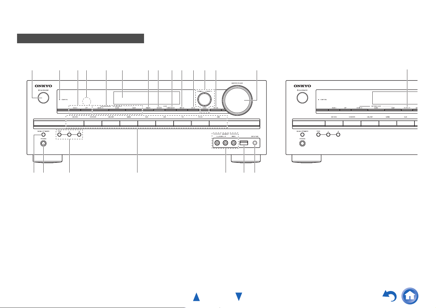
Front & Rear Panels
Front Panel
(North American, Brazilian and Taiwanese models) (Asian models)
Safety Information and Introduction
a
bc
p
For detailed information, see the pages in parentheses.
a 8ON/STANDBY button (18)
b HDMI THRU indicator (46)
c ZONE 2, OFF buttons (50)
d Remote control sensor (4)
e LISTENING MODE buttons (29)
f Display (8)
g DIMMER button (North American, Brazilian and
Taiwanese models) (34)
h MEMORY button (24)
i TUNING MODE button (23)
d
qo
e gf h ij k lm n
r s
tu
j DISPLAY button (35)
k SETUP button (36)
l TUNING q/w, PRESET e/r (23), cursor and
ENTER buttons
m RETURN button
n MASTER VOLUME control (19)
o MUSIC OPTIMIZER button (35, 48)
p PHONES jack (35)
q TONE and Tone Level buttons (47)
r Input selector buttons (19)
s AUX INPUT AUDIO and VIDEO jacks (15)
v
t USB port (15, 21, 22)
u SETUP MIC jack (26)
v RT/PTY/TP button (Asian models) (24)
En-7
Page 8
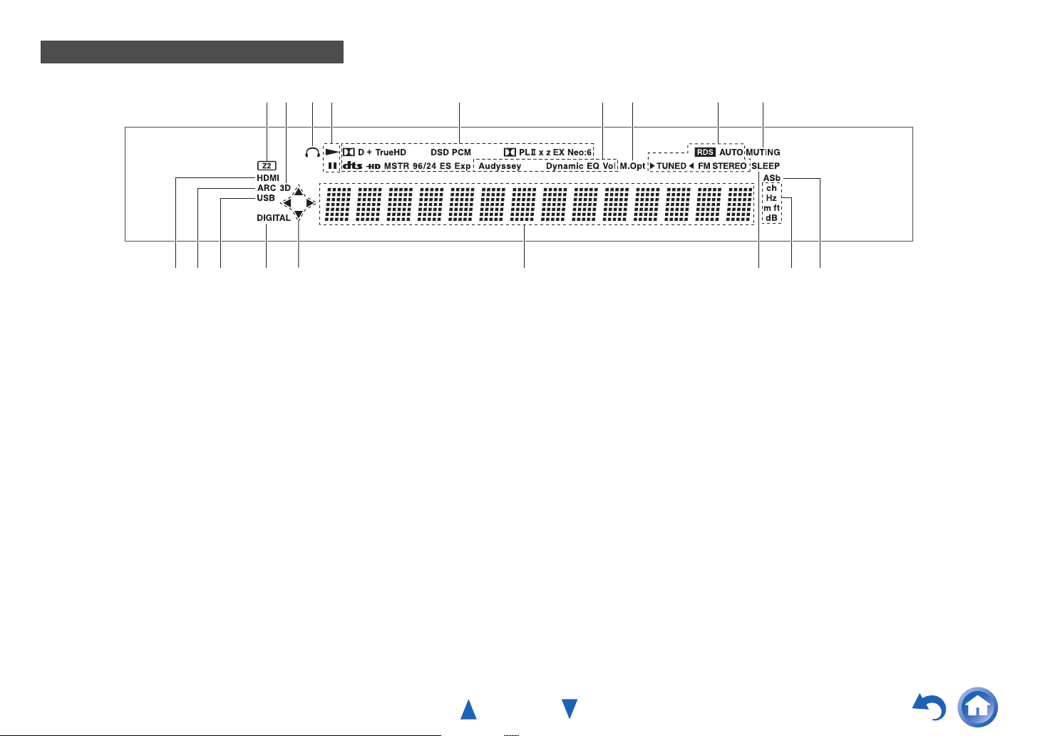
Display
Safety Information and Introduction
jd m n pk ojl
For detailed information, see the pages in parentheses.
a Z2 (Zone 2) indicator (50)
b 3D indicator
This lights when a 3D input signal is detected.
c Headphone indicator (35)
d 1, 3 and cursor indicators (22)
e Listening mode and format indicators (29, 44)
f Audyssey indicator (26, 42)
Dynamic EQ indicator (43)
Dynamic Vol indicator (43)
g M.Opt (Music Optimizer) indicator (35, 48)
h Tuning indicators
RDS indicator (excluding North American,
Brazilian and Taiwanese models) (24)
AUTO indicator (23)
TUNED indicator (23)
FM STEREO indicator (23)
i MUTING indicator (34)
dce hg
j Input indicators (62)
HDMI indicator (46, 62)
DIGITAL indicator
k ARC (Audio Return Channel) indicator (47)
l USB indicator (21, 22)
m Message area
n SLEEP indicator (34)
o Channel/Unit indicators
ch indicator
Hz indicator
m/ft indicator
dB indicator
p ASb (Auto Standby) indicator (45)
fa bi
En-8
Page 9
Safety Information and Introduction
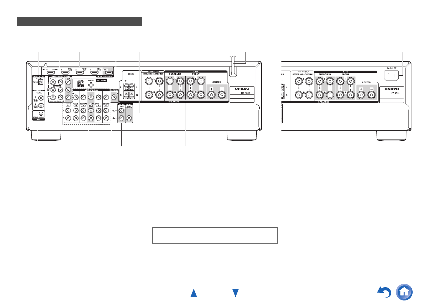
Rear Panel
(North American and Asian models) (Brazilian and Taiwanese models)
a b c
g
a DIGITAL IN COAXIAL and OPTICAL jacks
b COMPONENT VIDEO IN and OUT jacks
c HDMI IN and OUT jacks
d FM ANTENNA jack and AM ANTENNA terminal
e SUBWOOFER PRE OUT jack
f Power cord (North American and Asian models)
g uREMOTE CONTROL jack
h Composite video and analog audio jacks
(BD/DVD IN, VCR/DVR IN and OUT, CBL/SAT IN,
GAME IN, TV/CD IN)
h i
d
j k
e
i MONITOR OUT V jack
j ZONE 2 LINE OUT jacks
k SPEAKERS terminals
(CENTER, FRONT, SURROUND, SURROUND
BACK or FRONT HIGH, ZONE 2)
l AC INLET (Brazilian and Taiwanese models)
See “Connecting the AV Receiver” for connection
(➔ pages 11 to 17).
f
l
En-9
Page 10
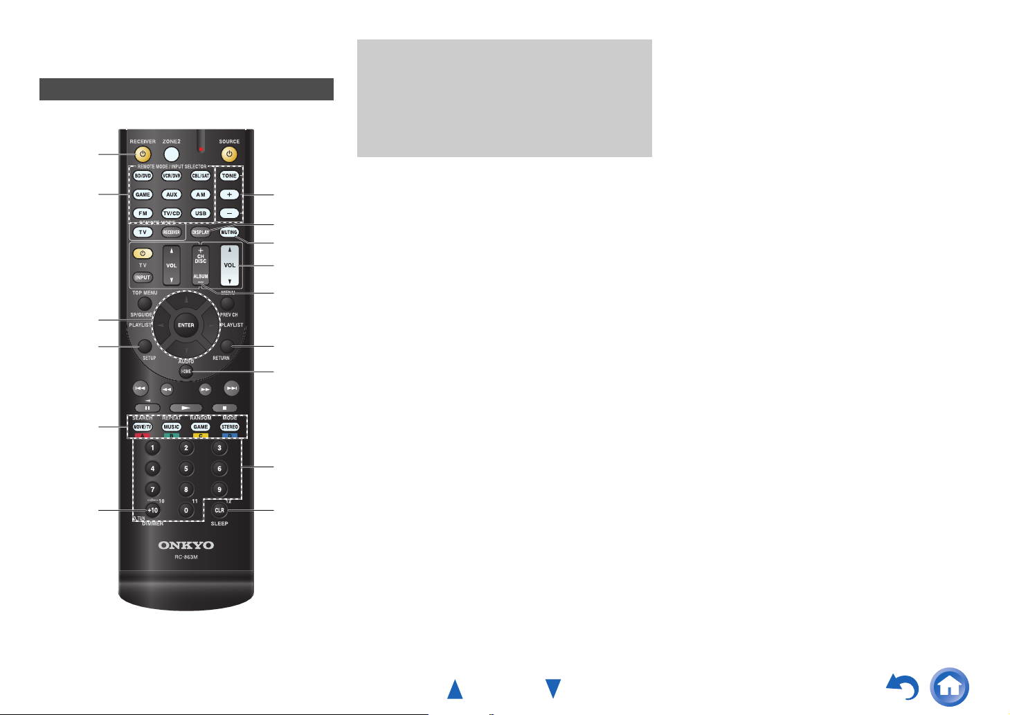
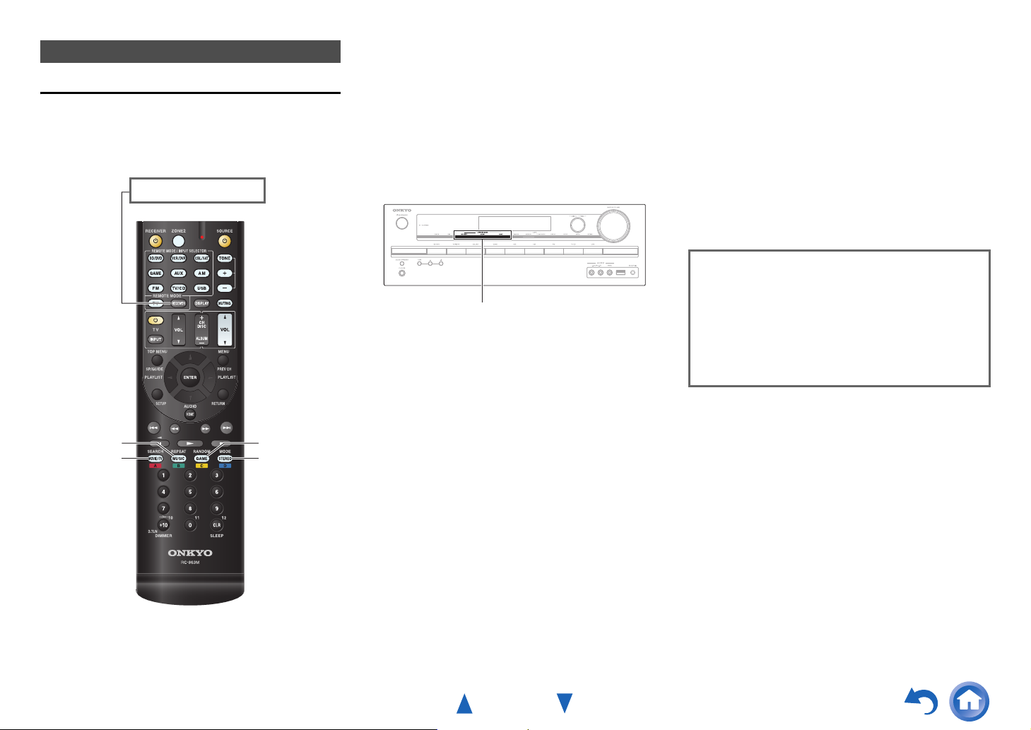
Remote Controller
Controlling the AV Receiver
*1
a
*1
b
ac
d
e
g
hc
*1
i
*1
j
d
k
l
To control the AV receiver, press RECEIVER to select
Receiver mode.
You can also use the remote controller to control
Onkyo Blu-ray Disc/DVD player, CD player, and
other components.
See “Entering Remote Control Codes” for more
details (➔ page 53).
For detailed information, see the pages in parentheses.
a 8 button (18)
b REMOTE MODE/INPUT SELECTOR buttons (19)
c q/w/e/r and ENTER buttons
d SETUP button (36)
e Listening Mode buttons (29)
f DIMMER button (34)
g TONE and Tone Level buttons (47)
h DISPLAY button (35)
i MUTING button (34)
j VOL q/w button (19)
k RETURN button
l HOME button (34)
m SLEEP button (34)
Safety Information and Introduction
■ Controlling the tuner
To control the AV receiver’s tuner, press AM or FM (or
RECEIVER).
a q/w buttons (23)
b D.TUN button (23)
c DISPLAY button
d CH +/– button (24)
e Number buttons (23)
*1
These buttons can also be used when a REMOTE MODE
other than Receiver mode is selected.
bf
e
m
En-10
Page 11
Connections
Connecting the AV Receiver
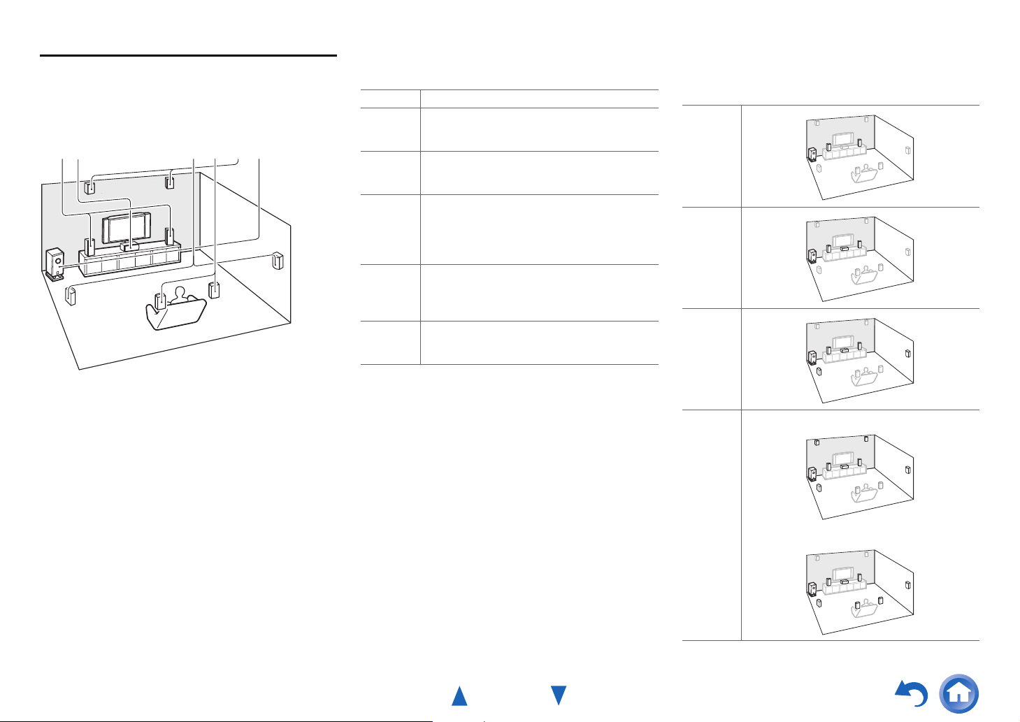
Connecting Your Speakers
Speaker Configuration
The following table indicates the channels you should use
depending on the number of speakers that you have.
No matter how many speakers you use, a powered
subwoofer is recommended for a really powerful and solid
bass.
To get the best from your surround sound system, you need
to set the speaker settings automatically (➔ page 26) or
manually (➔ page 39).
Number of speakers 2 3 4 5 6 7 7
Front speakers ✔✔✔✔✔✔✔
Center speaker ✔✔✔✔✔
Surround speakers ✔✔✔✔✔
Surround back speaker
Surround back speakers
Front high speakers
*1
If you’re using only one surround back speaker, connect it to
the SURROUND BACK or FRONT HIGH L terminals.
*2
Front high and surround back speakers cannot be used at the
same time.
*1*2
*2
*2
Connecting the Speaker Cables
✔
✔
✔
Surround back/
front high
right
Surround back/
front high
left
Surround
right
■ Screw-type speaker terminals
Strip 1/2" to 5/8" (12 to 15 mm) of insulation from the ends
of the speaker cables, and twist the bare wires tightly, as
shown (Supplied speaker cables are already stripped).
1/2" to 5/8" (12 to 15 mm)
Surround
left
Front right Front left
Center
■ Push-type speaker terminals
Strip 3/8" to 1/2" (10 to 12 mm) of insulation from the ends
of the speaker cables, and twist the bare wires tightly, as
shown.
3/8" to 1/2"(10 to 12 mm)
The following illustration shows how to connect the
speakers to each pair of terminals. If you’re using only one
surround back speaker, connect it to the SURROUND
BACK or FRONT HIGH L terminals.
Tip
• You can specify whether surround back or front high speakers are
connected in the “4. Sp Config (Speaker Configuration)” menu
(➔ page 39) or during Audyssey 2EQ
Speaker Setup (➔ page 26).
®
Room Correction and
■ Banana Plugs (North American and Brazilian
models)
• If you are using banana plugs, tighten the speaker
terminal before inserting the banana plug.
• Do not insert the speaker code directly into the center
hole of the speaker terminal.
En-11
Page 12
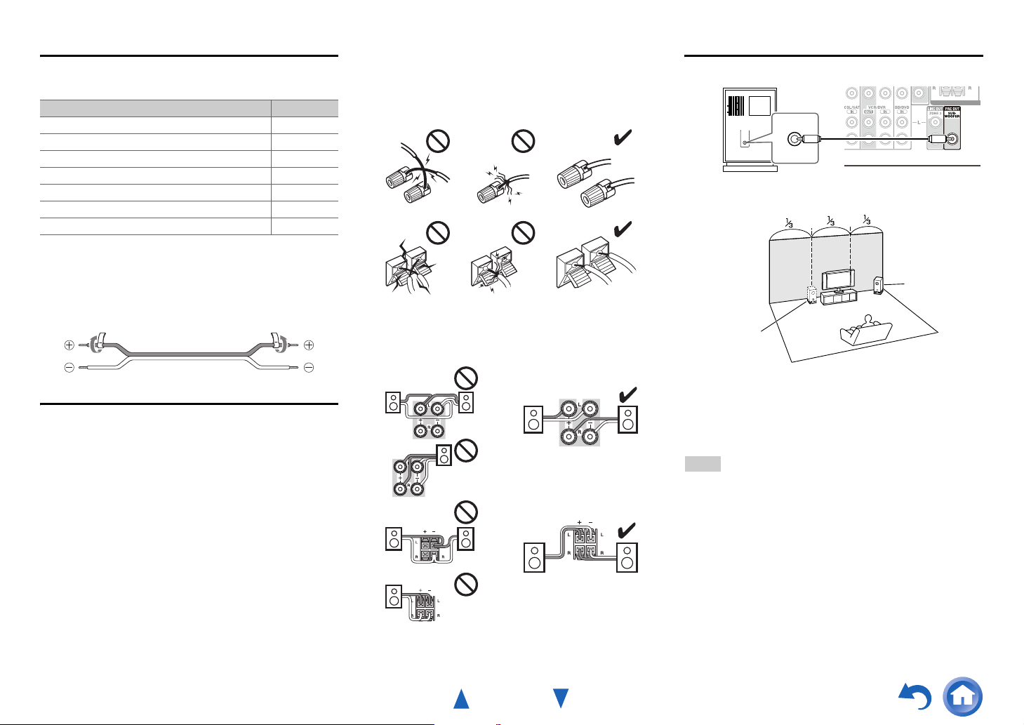
Connecting the Speaker Cables
The speaker terminals are color-coded for identification
purpose.
Speaker Color
Front left, Zone 2 left White
Front right, Zone 2 right Red
Center Green
Surround left Blue
Surround right Gray
Surround back left, Front high left Brown
Surround back right, Front high right Tan
(Taiwanese models) The supplied speaker cable labels are
also color-coded and you should attach them to the positive
(+) side of each speaker cable in accordance with the table
above. Then all you need to do is to match the color of each
label to the corresponding speaker terminal.
• Be careful not to short the positive and negative wires.
Doing so may damage the AV receiver.
• Make sure the metal core of the wire does not have
contact with the AV receiver’s rear panel. Doing so may
damage the AV receiver.
• Don’t connect more than one cable to each speaker
terminal. Doing so may damage the AV receiver.
• Don’t connect one speaker to several terminals.
Connections
Using a Powered Subwoofer
LINE INPUT
LINE INPUT
Powered subwoofer
Corner
position
1/3 of wall
position
Speaker Connection Precautions
Read the following before connecting your speakers:
• You can connect speakers with an impedance of between
6 and 16 ohms. If you use speakers with a lower
impedance, and use the amplifier at high volume levels
for a long period of time, the built-in amp protection
circuit may be activated.
• Disconnect the power cord from the wall outlet before
making any connections.
• Read the instructions supplied with your speakers.
• Pay close attention to speaker wiring polarity. In other
words, connect positive (+) terminals only to positive (+)
terminals, and negative (–) terminals only to negative (–)
terminals. If you get them the wrong way around, the
sound will be out of phase and will sound unnatural.
• Unnecessarily long, or very thin speaker cables may
affect the sound quality and should be avoided.
To find the best position for your subwoofer, while playing
a movie or some music with good bass, experiment by
placing your subwoofer at various positions within the
room, and choose the one that provides the most satisfying
results.
Tip
• If your subwoofer is unpowered and you’re using an external
amplifier, connect the subwoofer pre out jack to an input on the
amplifier.
En-12
Page 13
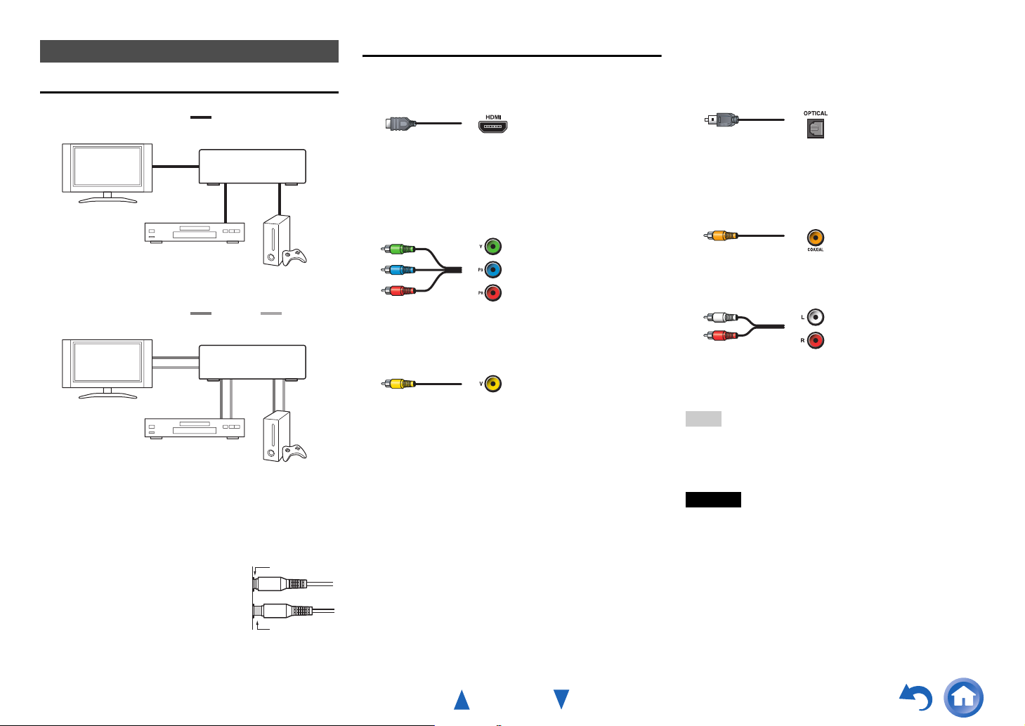
About AV Connections
Connecting AV components
a
HDMI cable
TV, projector, etc.
: Video & Audio
AV Cables and Jacks
■ HDMI
HDMI connections can carry digital video and audio.
Connections
■ Optical digital audio
Optical digital connections allow you to enjoy digital
sound such as PCM
*1
, Dolby Digital or DTS. The audio
quality is the same as coaxial.
AV receiver
Blu-ray Disc/
DVD player
Other cables
TV, projector, etc.
Blu-ray Disc/
DVD player
Game console
: Video : Audio
AV receiver
Game console
• Before making any AV connections, read the manuals
supplied with your AV components.
• Don’t connect the power cord until you’ve completed and
double-checked all AV connections.
• Push plugs in all the way to make
Right!
good connections (loose connections
can cause noise or malfunctions).
• To prevent interference, keep audio
and video cables away from power
Wrong!
cords and speaker cables.
■ Component video
Component video separates the luminance (Y) and color
difference signals (PB, PR), providing the best picture
quality (some TV manufacturers label their component
video sockets slightly differently).
Y
P
B
PR
Green
Blue
Red
■ Composite video
Composite video is commonly used on TVs, VCRs, and
other video equipment.
Yellow
■ Coaxial digital audio
Coaxial digital connections allow you to enjoy digital
*1
sound such as PCM
, Dolby Digital or DTS. The audio
quality is the same as optical.
Orange
■ Analog audio (RCA)
Analog audio connections (RCA) carry analog audio.
White
Red
*1
For PCM signals, the supported sampling rates are
32/44.1/48/88.2/96 kHz. With HDMI connections, 176.4 and
192 kHz are also supported.
Note
• The AV receiver does not support SCART plugs.
• The AV receiver’s optical digital jacks have shutter-type covers
that open when an optical plug is inserted and close when it’s
removed. Push plugs in all the way.
Caution
• To prevent shutter damage, hold the optical plug straight
when inserting and removing.
En-13
Page 14
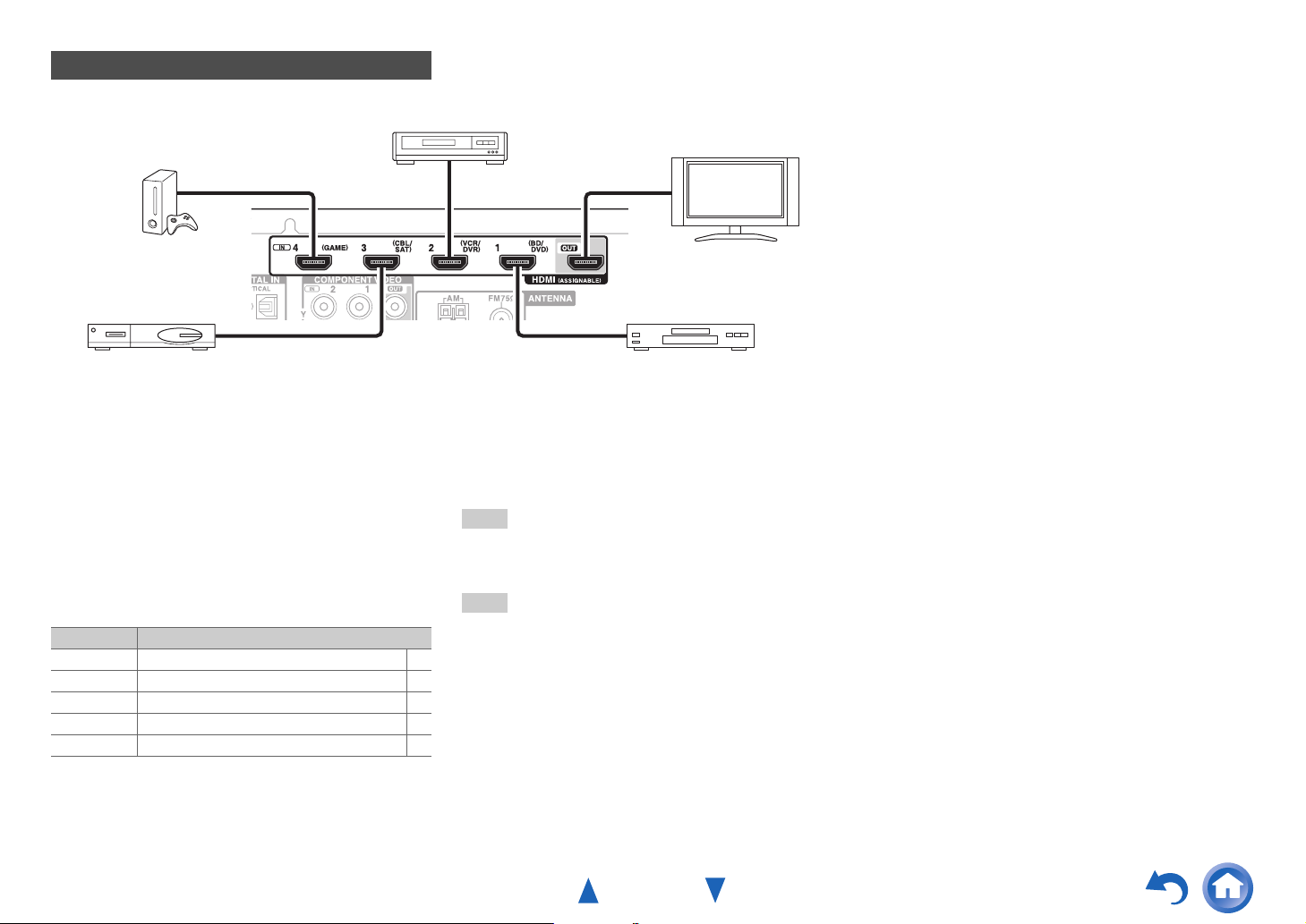
Connecting Components with HDMI
VCR or DVD recorder/digital video recorder
Connections
Game console
Satellite/cable set-top box, etc. Blu-ray Disc/DVD player
*
If your TV doesn’t support Audio Return Channel (ARC), you
need to connect an optical digital cable together with the HDMI
cable to the AV receiver.
*
When listening to an HDMI component through the AV
receiver, set the HDMI component so that its video can be seen
on the TV screen (on the TV, select the input of the HDMI
component connected to the AV receiver). If the TV power is off
or the TV is set to another input source, this may result in no
sound from the AV receiver or the sound may be cut off.
Connect your components to the appropriate jacks. The
default input assignments are shown below.
✔: Assignment can be changed (➔ page 38).
Jack Components
HDMI IN1 Blu-ray Disc/DVD player ✔
HDMI IN2 VCR or DVD recorder/digital video recorder ✔
HDMI IN3 Satellite/cable set-top box, etc. ✔
HDMI IN4 Game console ✔
HDMI OUT TV, projector, etc.
See also:
• “Connection Tips and Video Signal Path” (➔ page 62)
• “Using an RIHD-compatible TV, Player, or Recorder”
(➔ page 63)
• “About HDMI” (➔ page 65)
Tip
• To listen to the audio of a component connected via HDMI
through your TV’s speakers, enable “HDMI Through”
(➔ page 46) and set the AV receiver to standby mode.
Note
• In the case of Blu-ray Disc/DVD players, if no sound is output
despite following the above-mentioned procedure, set your Bluray Disc/DVD player’s HDMI audio settings to PCM.
TV, projector, etc.
■ Audio Return Channel (ARC) function
Audio Return Channel (ARC) function enables an HDMI
capable TV to send the audio stream to the HDMI OUT of
the AV receiver.
• This function can be used when:
– Your TV is ARC capable, and
–The TV/CD input selector is selected, and
–“HDMI CEC (RIHD)” is set to “On” (➔ page 46), and
–“Audio Return Ch (ARC)” is set to “Auto” (➔ page 47).
En-14
Page 15

Connections
Connecting Your Components
A CB
ED F
Connect your components to the appropriate jacks. The
default input assignments are shown below.
See “Connection Tips and Video Signal Path” for more
information (➔ page 62).
The on-screen menus appear only on a TV that is
connected to the HDMI OUT. If your TV is connected
to other video outputs, use the AV receiver’s display
when changing settings.
✔: Assignment can be changed (➔ pages 38, 39).
No. Jack/Port Components
AUX INPUT
A
VIDEO Camcorder, etc.
AUDIO L/R
USB, AUX INPUT
B
C
D
E
F
*1
VIDEO
*2
USB
DIGITAL IN
OPTICAL (TV/CD) TV, CD player ✔
COAXIAL 1 (BD/DVD) Blu-ray Disc/DVD player ✔
COAXIAL 2 (CBL/SAT) Satellite/cable set-top box,
COMPONENT VIDEO
IN 1 (BD/DVD) Blu-ray Disc/DVD player,
IN 2 (CBL/SAT) Satellite/cable set-top box,
OUT TV, projector, etc.
MONITOR OUT TV, projector, etc.
BD/DVD IN Blu-ray Disc/DVD player
VCR/DVR IN VCR, DVD recorder/
CBL/SAT IN Satellite/cable set-top box,
GAME IN Game console, RI dock
TV/CD IN TV, CD player, cassette
iPod/iPhone (video
playback)
iPod/iPhone, MP3 player,
USB flash drive
RI dock, etc.
RI dock
RI dock, etc.
digital video recorder, RI
dock
etc.
tape deck, MD, CD-R,
Turntable
*3
, RI dock
Note
*1
When USB input is selected, you can input video signals from
the AUX INPUT VIDEO jack. Video signals input from AUX
INPUT VIDEO will be output from the MONITOR OUT jack.
*2
Do not connect the AV receiver’s USB port to a USB port on
your computer. Music on your computer cannot be played
through the AV receiver in this way.
*3
Connect a turntable (MM) that has a phono preamp built-in. If
your turntable (MM) doesn’t have it, you’ll need a
commercially available phono preamp.
If your turntable has a moving coil (MC) type cartridge, you’ll
need a commercially available MC head amp or MC
transformer as well as a phono preamp. See your turntable’s
manual for details.
• With connection D, you can enjoy Dolby Digital and
DTS. (To record or listen the audio in Zone 2 as well, use
D and F.)
• With connection F, you can listen to and record audio
✔
from external components while you are in Zone 2.
• With connection F, if your Blu-ray Disc/DVD player has
both the main stereo and multichannel outputs, be sure to
✔
connect to the main stereo.
■ How to record a video source
✔
With the connections described above, you cannot record
the videos through the AV receiver. See “Recording” about
connections for video recording (➔ page 35).
En-15
Page 16

Connections
Connecting Onkyo RI Components
Make sure that each Onkyo component is
1
connected with an analog audio cable (connection
F in the hookup examples) (➔ page 15).
Make the u connection (see the illustration).
2
If you’re using an RI Dock or cassette tape deck,
3
change the Input Display (➔ page 35).
With u (Remote Interactive), you can use the following
special functions:
■ System On/Auto Power On
When you start playback on a component connected via
u while the AV receiver is on standby, the AV
receiver will automatically turn on and select that
component as the input source.
■ Direct Change
When playback is started on a component connected via
u, the AV receiver automatically selects that
component as the input source.
■ Remote Control
You can use the AV receiver’s remote controller to
control your other u-capable Onkyo components,
pointing the remote controller at the AV receiver’s
remote control sensor instead of the component. You
must enter the appropriate remote control code first
(➔ page 54).
L R
ANALOG
e.g., cassette tape deck
RI Dock
Note
•Use only u cables for u connections. u cables are supplied
with Onkyo components.
• Some components have two u jacks. You can connect either
one to the AV receiver. The other jack is for connecting
additional u-capable components.
• Connect only Onkyo components to u jacks. Connecting other
manufacturer’s components may cause a malfunction.
• Some components may not support all u functions. Refer to the
manuals supplied with your other Onkyo components.
• While Zone 2 is on, the System On/Auto Power On and Direct
Change u functions do not work.
AUDIO OUT
ANALOG
AUDIO OUT
L R
Connecting a Recording Component
See “Recording” for details on recording (➔ page 35).
L R
AUDI O
VCR, DVD recorder,
cassette tape deck,
CDR, MD recorder, etc.
Note
• The AV receiver must be turned on for recording. Recording is
not possible while it’s in standby mode.
• If you want to record directly from your TV or playback VCR to
the recording VCR without going through the AV receiver,
connect the TV/VCR’s audio and video outputs directly to the
recording VCR’s audio and video inputs. See the manuals
supplied with your TV and VCR for details.
• Video signals connected to composite video inputs can be
recorded only via composite video outputs. For example, if your
TV/VCR is connected to a composite video input, the recording
VCR must be connected to a composite video output.
• The surround sound and DSP listening modes cannot be recorded.
• Copy-protected Blu-ray Discs and DVDs cannot be recorded.
• Sources connected to a digital input cannot be recorded. Only
analog inputs can be recorded.
• DTS signals will be recorded as noise, so don’t attempt analog
recording of DTS CDs or LDs.
VIDEO
IN
IN
En-16
Page 17
Connections
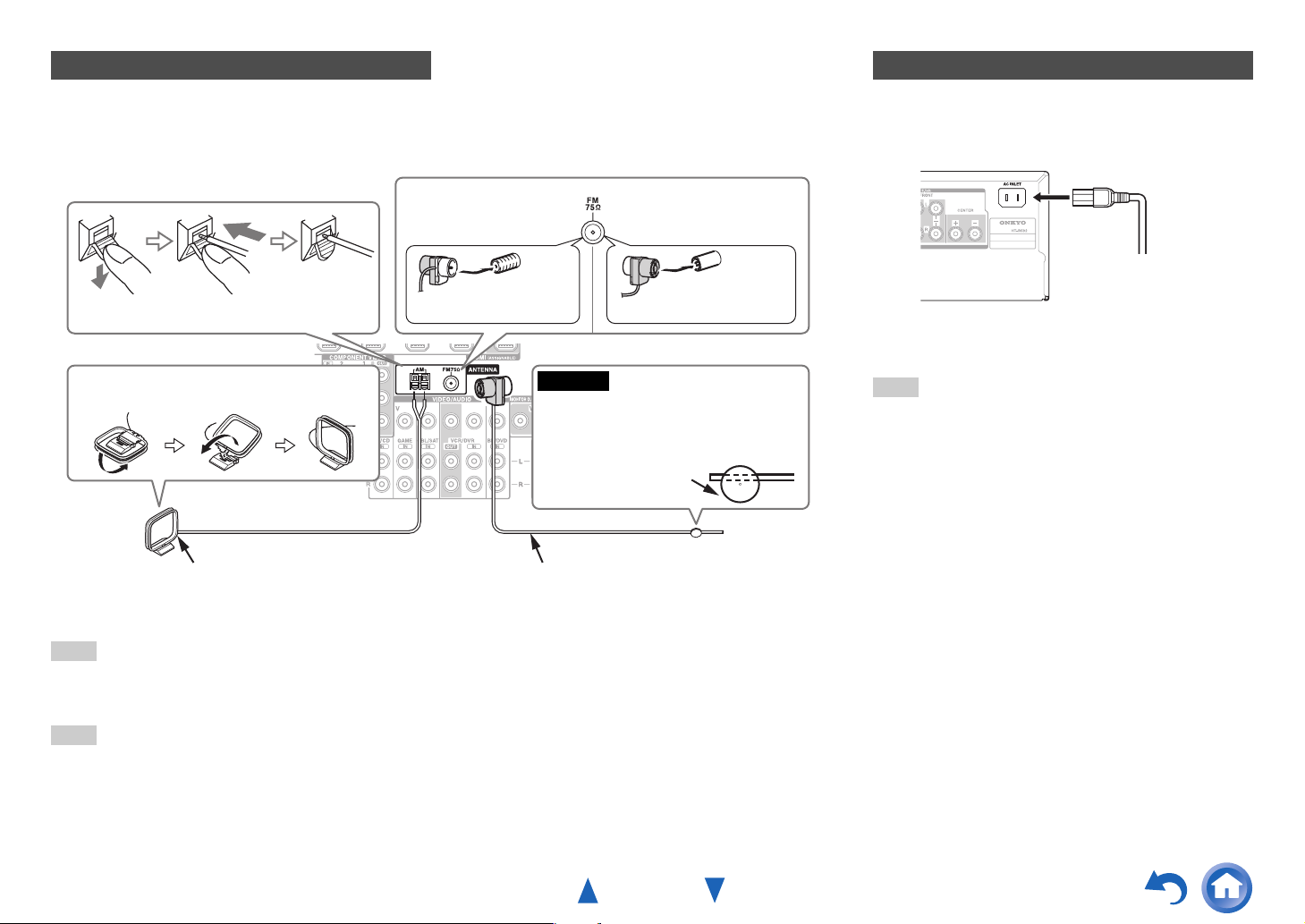
Connecting the Antennas
This section explains how to connect the supplied indoor FM antenna and AM loop antenna.
The AV receiver won’t pick up any radio signals without any antenna connected, so you must connect the antenna to use
the tuner.
North American,
Brazilian and Taiwanese
models
Push. Insert wire. Release.
Assembling the AM loop antenna
Insert the plug fully
into the jack.
Caution
• Be careful not to injure yourself when
using thumbtacks.
AM loop antenna (supplied)
Note
• Once your AV receiver is ready for use, you’ll need to tune into a radio station and position the antenna to achieve the best possible
reception.
• Keep the AM loop antenna as far away as possible from your AV receiver, TV, speaker cables, and power cords.
Tip
• If you cannot achieve good reception with the supplied indoor FM antenna, try a commercially available outdoor FM antenna instead.
• If you cannot achieve good reception with the supplied indoor AM loop antenna, try using it with a commercially available outdoor AM
antenna.
Indoor FM antenna (supplied)
Asian models
Insert the plug fully
into the jack.
Thumbtacks, etc.
Connecting the Power Cord
(Brazilian and Taiwanese models)
1
Connect the supplied power cord to the AV
receiver’s AC INLET.
To AC wall outlet
Plug the power cord into an AC wall outlet.
2
Note
• Before connecting the power cord, connect all of your
speakers and AV components.
• Turning on the AV receiver may cause a momentary power surge
that might interfere with other electrical equipment on the same
circuit. If this is a problem, plug the AV receiver into a different
branch circuit.
• Do not use a power cord other than the one supplied with the AV
receiver. The supplied power cord is designed exclusively for use
with the AV receiver and should not be used with any other
equipment.
• Never disconnect the power cord from the AV receiver while the
other end is still plugged into a wall outlet. Doing so may cause
an electric shock. Always disconnect the power cord from the
wall outlet first, and then the AV receiver.
En-17
Page 18
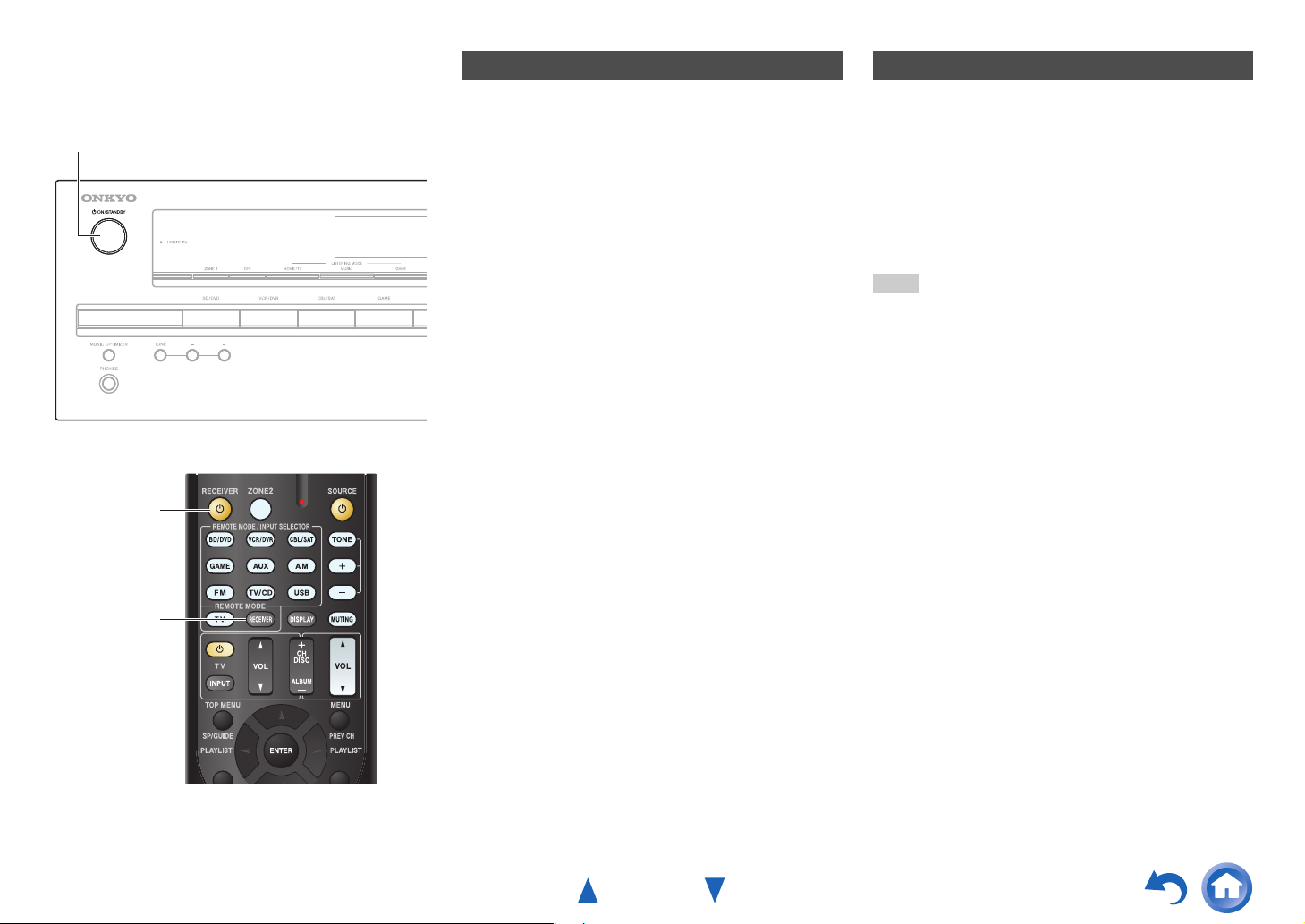
Turning On & Basic Operations
Turning On/Off the AV Receiver
8ON/STANDBY
8
Turning On
Press 8ON/STANDBY on the front panel.
1
or
Press RECEIVER followed by 8 on the remote
controller.
The AV receiver comes on, and its display lights.
Turning Off
Press 8ON/STANDBY on the front panel.
1
or
Press RECEIVER followed by 8 on the remote
controller.
The AV receiver will enter standby mode. To prevent
any loud surprises when you turn on the AV receiver,
always turn down the volume before you turn it off.
Tip
• For details on power management settings, see “Auto Standby”
(➔ page 45).
RECEIVER
En-18
Page 19

Playback
The on-screen menus appear only on a TV that is
connected to the HDMI OUT. If your TV is connected
to other video outputs, use the AV receiver’s display
when changing settings.
Playing the Connected Component
■ Operating with the remote controller
INPUT SELECTOR
Turning On & Basic Operations
■ Operating on the AV receiver
Input selector buttons
MASTER VOLUME LISTENING MODE
This section describes the procedure for using the
remote controller unless otherwise specified.
RECEIVER
VOL q/w
Listening mode buttons
Press RECEIVER followed by an INPUT
1
SELECTOR button.
Start playback on the source component.
2
See also:
• “Playing an iPod/iPhone via USB” (➔ page 21)
• “Playing a USB Device” (➔ page 22)
• “Listening to AM/FM Radio” (➔ page 23)
• “iPod/iPhone Playback via Onkyo Dock”
(➔ page 51)
• “Controlling Other Components” (➔ page 53)
To adjust the volume, use VOL q/w.
3
Select a listening mode and enjoy!
4
See also:
• “Using the Listening Modes” (➔ page 29)
Use the input selector buttons to select the input
1
source.
Start playback on the source component.
2
To adjust the volume, use the MASTER VOLUME
3
control.
Select a listening mode and enjoy!
4
En-19
Page 20

Turning On & Basic Operations
Controlling Contents of USB Devices
Press USB
first.
h
i
a
b
j
c
d
e
f
g
k
l
m
n
o
p
TOP MENU
a
This button displays the top menu for each media or service.
b
q/w and ENTER
These buttons navigate through the menus.
e/r
This button cycles through pages.
PLAYLIST e/r
In Standard Mode (iPod/iPhone), this button selects
playlists.
c
1
This button starts playback.
d
7
This button selects the beginning of the current song.
Pressing this button twice selects the previous song.
e
5
This button fast-reverses the current song.
f
3
This button pauses playback.
SEARCH
g
You can toggle between the playback screen and the list
screen during playback.
DISPLAY
h
This button switches between song information.
CH +/–
i
In Standard Mode (iPod/iPhone), this button selects albums.
RETURN
j
This button returns to the previous menu.
k
6
This button selects the next song.
l
4
This button fast-forwards the current song.
m
2
This button stops playback.
MODE
n
You can switch between Standard Mode and Extended
Mode.
RANDOM
o
This button performs random playback.
REPEAT
p
Press this button repeatedly to cycle through the repeat
modes.
Tip
• See “Controlling Other Components” about the operation of
other components (➔ page 53).
Note
• The buttons you can use will differ depending on the devices and
media used for playback.
En-20
Page 21
Turning On & Basic Operations
Understanding Icons on the Display
This section describes icons that appear on the AV
receiver’s display during media playback.
Icon Description
Folder
Track
Playback
Pause
Fast Forward
Fast Reverse
Artist
Album
Repeat One Track
Repeat Folder (USB Device)
Repeat
Shuffle
Shuffle Album (iPod/iPhone)
Playing an iPod/iPhone via USB
The on-screen menus appear only on a TV that is
connected to the HDMI OUT.
This section explains how to play music files on the
iPod/iPhone.
Compatible iPod/iPhone models
Made for:
iPod touch (1st, 2nd, 3rd, 4th and 5th generation),
iPod classic, iPod nano (2nd, 3rd, 4th, 5th, 6th and 7th
generation), iPhone 5, iPhone 4S, iPhone 4, iPhone 3GS,
iPhone 3G, iPhone
Press USB to select the “USB” input.
1
Connect the USB cable that comes with the
2
iPod/iPhone to the USB port on the front of the AV
receiver.
While reading the contents of your iPod/iPhone, the
message “Connecting...” appears on the AV
receiver’s display.
A list of your iPod/iPhone model’s contents appears
(Extended Mode).
Use q/w to select a folder, and then press ENTER to
3
open it.
Tip
• If you want to operate using the iPod/iPhone or the remote
controller, press MODE to switch to Standard mode.
• When you disconnect the iPod/iPhone, the AV receiver
remembers the current mode. This means that if you
disconnect when in Extended Mode, the AV receiver will
start in Extended Mode the next time you connect the
iPod/iPhone.
• You can also use the q/w, ENTER and TUNING MODE
buttons on the front panel. TUNING MODE allows you to
switch modes.
• When connecting your iPod/iPhone with a USB cable, we
recommend you use an official USB cable from Apple Inc.
Use q/w to select a music file, and press ENTER or
4
1 to start playback.
Note
• While the message “Connecting...” appears on the AV receiver’s
display, do not disconnect the USB cable supplied with your
iPod/iPhone or the USB device from the USB port.
• If you connect an iPod or iPhone to the USB port, no sound will
be output from the headphones jack.
Extended Mode Control
The content information is displayed (lists are displayed),
and you can control the content while looking at the screen.
Top screen list:
Playlists, Artists, Albums, Genres, Songs, Composers,
Shuffle Songs, Now Playing.
Standard Mode Control
The content information is not displayed, but can be
operated using the iPod/iPhone or the remote controller.
En-21
Page 22

Playing a USB Device
The on-screen menus appear only on a TV that is
connected to the HDMI OUT.
This section explains how to play music files from a USB
device (e.g., USB flash drives and MP3 players).
See also:
• “USB Features” (➔ page 66).
Press USB to select the “USB” input.
1
Plug your USB device into the AV receiver’s USB
2
port.
While reading the contents of your USB device, the
message “Connecting...” appears on the AV
receiver’s display.
Press ENTER.
3
A list of the device’s contents appears. To open a
folder, use q/w to select it, and then press ENTER.
Use q/w to select a music file, and press ENTER or
4
1 to start playback.
Turning On & Basic Operations
Note
• While the message “Connecting...” appears on the AV receiver’s
display, do not disconnect the USB cable supplied with your
iPod/iPhone or the USB device from the USB port.
En-22
Page 23
Listening to AM/FM Radio
This section describes the procedure using the buttons
on the front panel unless otherwise specified.
Using the Tuner
With the built-in tuner you can enjoy AM and FM radio
stations. You can store your favorite stations as presets for
quick selection.
You can also change the frequency steps (➔ page 45).
Press AM or FM to select either “AM” or “FM”.
1
In this example, FM has been selected.
Band Frequency
(Actual display depends on the country.)
Tuning into Radio Stations
■ Auto tuning mode
Press TUNING MODE so that the AUTO indicator
1
lights on the AV receiver’s display.
Press TUNING q/w.
2
Searching stops when a station is found.
When tuned into a station, the TUNED indicator
lights. When tuned into a stereo FM station, the FM
STEREO indicator lights as shown.
TUNED
AUTO
FM STEREO
Tip
• Tuning into weak FM stereo stations
If the signal from a stereo FM station is weak, it may be
impossible to get good reception. In this case, switch to
manual tuning mode and listen to the station in mono.
Turning On & Basic Operations
■ Manual tuning mode
In manual tuning mode, FM stations will be in mono.
Press TUNING MODE so that the AUTO indicator
1
goes off on the AV receiver’s display.
Press and hold TUNING q/w.
2
The frequency stops changing when you release the
button.
Press the buttons repeatedly to change the frequency
one step at a time.
■ Tuning into stations by frequency
You can tune into AM and FM stations directly by entering
the appropriate frequency.
On the remote controller, press AM or FM to select
1
“AM” or “FM”, followed by D.TUN.
(Actual display depends on the country.)
Within 8 seconds, use the number buttons to enter
2
the frequency of the radio station.
For example, to tune to 87.5 (FM), press 8, 7, 5 or 8,
7, 5, 0.
If you have entered the wrong number, you can retry
after 8 seconds.
En-23
Page 24
Presetting AM/FM Stations
You can store a combination of up to 40 of your favorite
AM/FM radio stations as presets.
Tune into the AM/FM station that you want to store
1
as a preset.
See the previous section.
Press MEMORY.
2
The preset number flashes.
(Actual display depends on the country.)
While the preset number is flashing (about 8
3
seconds), use PRESET e/r to select a preset from
1 through 40.
Press MEMORY again to store the station or
4
channel.
The station or channel is stored and the preset number
stops flashing.
Repeat this procedure for all of your favorite AM/FM
radio stations.
■ Selecting Presets
To select a preset, use PRESET e/r on the AV
1
receiver, or the remote controller’s CH +/–.
Tip
• You can also use the remote controller’s number buttons to
select a preset directly.
■ Deleting Presets
Select the preset that you want to delete.
1
See the previous section.
While holding down MEMORY, press TUNING
2
MODE.
The preset is deleted and its number disappears from
the AV receiver’s display.
Turning On & Basic Operations
Using RDS (excluding North American,
Brazilian and Taiwanese models)
RDS works only in areas where RDS broadcasts are
available.
When tuned into an RDS station, the RDS indicator lights.
When the station is broadcasting text information, the text
can be displayed.
■ What is RDS?
RDS stands for Radio Data System and is a method of
transmitting data in FM radio signals. It was developed by
the European Broadcasting Union (EBU) and is available
in most European countries. Many FM stations use it these
days. In addition to displaying text information, RDS can
also help you find radio stations by type (e.g., news, sport,
rock, etc.).
The AV receiver supports four types of RDS information:
PS (Program Service)
When tuned to an RDS station that’s broadcasting PS
information, the station’s name will be displayed. Pressing
DISPLAY will display the frequency for 3 seconds.
RT (Radio Text)
When tuned to an RDS station that’s broadcasting text
information, the text will be shown on the AV receiver’s
display as described in the next section.
PTY (Program Type)
This allows you to search for RDS radio stations by type
(➔ page 25).
TP (Traffic Program)
This allows you to search for RDS radio stations that
broadcast traffic information (➔ page 25).
En-24
Page 25

Note
• In some cases, the text characters displayed on the AV receiver
may not be identical to those broadcast by the radio station. Also,
unexpected characters may be displayed when unsupported
characters are received. This is not a malfunction.
• If the signal from an RDS station is weak, RDS data may be
displayed intermittently or not at all.
■ Displaying Radio Text (RT)
Press RT/PTY/TP once.
1
The RT information scrolls across the AV receiver’s
display.
Note
• The message “Waiting” may appear while the AV receiver
waits for the RT information.
• If the message “No Text Data” appears, no RT information
is available.
■ Finding Stations by Type (PTY)
You can search for radio stations by type.
Press RT/PTY/TP twice.
1
The current program type appears on the AV
receiver’s display.
Use PRESET e/r to select the type of program
2
you want.
See the table shown later in this chapter.
To start the search, press ENTER.
3
The AV receiver searches until it finds a station of the
type you specified, at which point it stops briefly
before continuing with the search.
When a station you want to listen to is found, press
4
ENTER.
If no stations are found, the message “Not Found”
appears.
■ Listening to Traffic News (TP)
You can search for stations that broadcast traffic news.
Press RT/PTY/TP three times.
1
If the current radio station is broadcasting TP (Traffic
Program), “[TP]” will appear on the AV receiver’s
display. If “TP” without square brackets appears, this
means that the station is not broadcasting TP.
To locate a station that is broadcasting TP, press
2
ENTER.
The AV receiver searches until it finds a station that’s
broadcasting TP.
If no stations are found, the message “Not Found”
appears.
Turning On & Basic Operations
RDS program types (PTY)
Type Display
None None
News reports News
Current affairs Affairs
Information Info
Sport Sport
Education Educate
Drama Drama
Culture Culture
Science and technology Science
Varied Varied
Pop music Pop M
Rock music Rock M
Middle of the road music Easy M
Light classics Light M
Serious classics Classics
Other music Other M
Weather Weather
Finance Finance
Children’s programmes Children
Social affairs Social
Religion Religion
Phone in Phone In
Travel Travel
Leisure Leisure
Jazz music Jazz
Country music Country
National music Nation M
Oldies music Oldies
Folk music Folk M
Documentary Document
Alarm test TEST
Alarm Alarm!
En-25
Page 26

Turning On & Basic Operations
Using Basic Functions
Using the Automatic Speaker Setup
With the supplied calibrated microphone, Audyssey 2EQ®
automatically determines the number of speakers
connected, their size for purposes of bass management,
optimum crossover frequencies to the subwoofer (if
present), and distances from the primary listening position.
Audyssey 2EQ then removes the distortion caused by room
acoustics by capturing room acoustical problems over the
listening area in both the frequency and time domain. The
result is clear, well-balanced sound for everyone.
Audyssey 2EQ can be used with Audyssey Dynamic EQ
and Audyssey Dynamic Volume
®
(➔ pages 42, 43).
Before using this function, connect and position all of your
speakers.
Audyssey 2EQ offers two ways of measuring: the
“Audyssey Quick Start” and “Audyssey 2EQ Full
Calibration”.
•“Audyssey Quick Start” uses the measurement from one
position to perform the speaker setting only.
•“Audyssey 2EQ Full Calibration” uses the
measurement from three positions to correct room
response in addition to the speaker setting.
The more positions are used in measuring, the better the
listening environment will become. We recommend using
a measurement from three positions to create the best
listening environment.
The Quick Start takes 2 minutes and Full Calibration takes
about 10 minutes.
Total measurement time varies depending on the number
of speakers.
®
Measurement procedure
To create a listening environment in your home theater that
all listeners will enjoy, Audyssey 2EQ takes measurements
at up to three positions within the listening area. Position
the microphone at ear height of a seated listener with the
microphone tip pointed directly at the ceiling using a
tripod. Do not hold the microphone in your hand during
measurements as this will produce inaccurate results.
a First measurement position
Also referred to as the Main Listening Position, this
refers to the most central position where one would
normally sit within the listening environment.
Audyssey 2EQ uses the measurements from this
position to calculate speaker distance, level, polarity,
and the optimum crossover value for the subwoofer.
b Second measurement position
The right side of the listening area.
c Third measurement position
The left side of the listening area.
The distances from position a to b and a to c must be
at least 1 meter (3.3 ft.).
TV
abc
: Listening area
ato c: Listening position
Note
• Make the room as quiet as possible. Background noise and Radio
Frequency Interference (RFI) can disrupt the room
measurements. Close windows, televisions, radios, air
conditioners, fluorescent lights, home appliances, light dimmers,
or other devices. Turn off the cell phone (even if it is not in use)
or place it away from all audio electronics.
• The microphone picks up test tones played through each speaker
as Audyssey 2EQ Room Correction and Speaker Setup runs.
• Audyssey 2EQ Room Correction and Speaker Setup cannot be
performed while a pair of headphones is connected.
En-26
Page 27
Turning On & Basic Operations
Turn on the AV receiver and the connected TV.
1
On the TV, select the input to which the AV receiver
is connected.
Note
• Before plugging the Speaker setup microphone to perform
Automatic Speaker Setup, please make sure that all your
connected speakers and subwoofers produce sound.
Set the speaker setup microphone at the Main
2
Listening Position a, and connect it to the SETUP
MIC jack.
SETUP MIC jack
Speaker setup microphone
The speaker setting menu appears.
Note
• The on-screen menus appear only on a TV that is connected
to the HDMI OUT. If your TV is connected to other video
outputs, use the AV receiver’s display when changing
settings.
When you’ve finished making the settings, press
3
ENTER.
Audyssey
Perform the
2EQ: Auto Setup
Powered Zone 2 No
SurrBk/FrontHigh < SurrBack >
Subwoofer Yes
“4. Sp Config (Speaker Configuration)”
according to your speaker configuration:
– Powered Zone 2 (➔ page 39)
– SurrBk/FrontHigh (➔ page 39)
– Subwoofer (➔ page 39)
If you use a powered subwoofer(s), go to step 4. If not,
go to step 5.
Adjust the subwoofer volume level to 75 dB, and
4
then press ENTER.
Test tones are played through the subwoofer. Use the
volume control on the subwoofer.
Note
• If your subwoofer does not have a volume control, disregard
the displayed level and press ENTER to proceed to the next
step.
• If you set the subwoofer’s volume control to its maximum
and the level displayed is lower than 75 dB, leave the
subwoofer’s volume control at its maximum and press
ENTER to proceed to the next step.
Use q/w to select “Audyssey Quick Start” or
5
“Audyssey 2EQ Full Calibration”, and then press
ENTER.
Press ENTER.
6
Audyssey 2EQ
®
Room Correction and Speaker Setup
starts.
Test tones are played through each speaker as
Audyssey 2EQ Room Correction and Speaker Setup
runs. This process takes a few minutes. Please refrain
from talking during measurements and do not stand
between speakers and the microphone.
Do not disconnect the speaker setup microphone
during Audyssey 2EQ Room Correction and Speaker
Setup, unless you want to cancel the setup.
If you select “Audyssey Quick Start”, you will go to
step 9.
Place the speaker setup microphone at the next
7
position, and then press ENTER.
Audyssey 2EQ performs more measurements. This
takes a few minutes.
When prompted, repeat step 7.
8
Use q/w to select an option, and then press ENTER.
9
2EQ: Auto Setup
<- Review Speaker Configuration ->
Subwoofer : Yes
Front : Small
Center : Small
Surround : Small
Front High : None
Surr Back : Small
Surr Back Ch : 2ch
Crossover : 100Hz
Save
Cancel
Audyssey
The options are:
` Save:
Save the calculated settings and exit
Audyssey 2EQ Room Correction and Speaker
Setup.
` Cancel:
Cancel Audyssey 2EQ Room Correction and
Speaker Setup.
En-27
Page 28
Turning On & Basic Operations
Tip
• You can view the calculated settings for the speaker
configuration, speaker distances, and speaker levels by
using e/r.
Use q/w to select a target, and use e/r to change
10
the setting.
After the results of Audyssey 2EQ have been saved,
the menu will display the “Audyssey” (➔ page 42),
“Dynamic EQ” (➔ page 43), “Dynamic Volume”
(➔ page 43) settings.
Note
•When “Audyssey Quick Start” has been used for
measurement, “Audyssey” cannot be selected.
• These settings are applied to all input selectors.
Press ENTER.
11
Disconnect the speaker setup microphone.
12
Note
• You can cancel Audyssey 2EQ Room Correction and Speaker
Setup at any point in this procedure simply by disconnecting the
setup microphone.
• Do not connect or disconnect any speakers during Audyssey 2EQ
Room Correction and Speaker Setup.
• If the AV receiver is muted, it will be unmuted automatically
when Audyssey 2EQ Room Correction and Speaker Setup starts.
• Changes to the room after Audyssey 2EQ Room Correction and
Speaker Setup requires you run Audyssey 2EQ Room Correction
and Speaker Setup again, as room EQ characteristics may have
changed.
Error Messages
While Audyssey 2EQ® Room Correction and Speaker
Setup is in progress, one of the error messages below may
appear.
2EQ: Auto Setup
Ambient noise is too high.
Retry
Cancel
The options are:
` Retry:
Try again.
` Cancel:
Cancel Audyssey 2EQ Room Correction and Speaker
Setup.
• Ambient noise is too high.
The background noise is too loud. Remove the source of
the noise and try again.
• Speaker Matching Error!
The number of speakers detected was different from that
of the first measurement. Check the speaker connection.
• Writing Error!
This message appears if saving fails. Try saving again. If
this message appears after 2 or 3 attempts, contact your
Onkyo dealer.
• Speaker Detect Error
This message appears if a speaker is not detected. “No”
means that no speaker was detected.
Tip
• See “Speaker Configuration” for appropriate settings
(➔ page 11).
Audyssey
Error message
Changing the Speaker Setup Manually
You can manually make changes to the settings found
during Audyssey 2EQ Room Correction and Speaker
Setup.
See also:
• “4. Sp Config (Speaker Configuration)” (➔ page 39)
• “5. Sp Distance (Speaker Distance)” (➔ page 40)
• “6. Level Cal (Level Calibration)” (➔ page 41)
Using a Powered Subwoofer
If you’re using a powered subwoofer and it outputs very
low-frequency sound at a low volume level, it may not be
detected by Audyssey 2EQ Room Correction and Speaker
Setup.
If the “Subwoofer” appears on the “Review Speaker
Configuration” screen as “No”, increase the subwoofer’s
volume to the half-way point, set it to its highest crossover
frequency, and then try running Audyssey 2EQ Room
Correction and Speaker Setup again. Note that if the
volume is set too high and the sound distorts, detection
issues may occur, so use an appropriate volume level. If the
subwoofer has a low-pass filter switch, set it to Off or
Direct. Refer to your subwoofer’s instruction manual for
details.
En-28
Page 29
Using the Listening Modes
Selecting Listening Modes
See “About Listening Modes” for detailed information
about the listening modes (➔ page 30).
■ Listening Mode Buttons
Press RECEIVER first.
MOVIE/TV, MUSIC, GAME
Turning On & Basic Operations
MOVIE/TV button
This button selects the listening modes intended for use
with movies and TV.
MUSIC button
This button selects the listening modes intended for use
with music.
GAME button
This button selects the listening modes intended for use
with video games.
STEREO button
This button selects the Stereo listening mode and All
Channel Stereo listening mode.
• The Dolby Digital and DTS listening modes can only be
selected if your Blu-ray Disc/DVD player is connected to
the AV receiver with a digital audio connection (coaxial,
optical, or HDMI).
• The listening modes you can select depends on the format
of the input signal. To check the format, see “Displaying
Source Information” (➔ page 35).
• While a pair of headphones is connected, you can select the
following listening modes: Direct, Stereo, and Mono.
MUSIC
MOVIE/TV
GAME
STEREO
En-29
Page 30
About Listening Modes
The AV receiver’s listening modes can transform your
listening room into a movie theater or concert hall, with
high fidelity and stunning surround sound.
■ Explanatory Notes
ab cd e
a Front speakers
b Center speaker
c Surround speakers
d Surround back speakers
e Front high speakers
f Subwoofer
f
Input Source
The following audio formats are supported by the listening
mode.
A
S
D
F
G
H
This is mono (monophonic) sound.
This is stereo (stereophonic) sound. Two
independent audio signal channels are reproduced
through two speakers.
This is 5.1-channel surround sound. This surround
system has five main channels of sound and a sixth
subwoofer channel (called the point-one channel).
This is 7.1-channel surround sound. This is a further
sound enhancement to 5.1-channel sound with two
additional speakers that provide greater sound
envelopment and more accurate positioning of
sounds.
This is DTS-ES surround sound. This surround
system can produce a discrete or a matrix-encoded
sixth channel from existing DTS 5.1 encoded
material.
This is Dolby Digital EX surround sound. This
provides a center back surround channel from 5.1channel sources.
Turning On & Basic Operations
Speaker Layout
The illustration shows which speakers are activated in each
channel. See “4. Sp Config (Speaker Configuration)” for
the speaker setup (➔ page 39).
Z
X
C
N
B
En-30
V
Page 31

■ Onkyo-Original DSP Listening Modes
Listening Mode Description Input
Orchestra
Or c e s t rah
*1
Suitable for classical or operatic music, this
mode emphasizes the surround channels in
order to widen the stereo image, and
simulates the natural reverberation of a large
hall.
Unplugged
Unp u gg edl
*1
Suitable for acoustic instruments, vocals,
and jazz, this mode emphasizes the front
stereo image, giving the impression of being
right in front of the stage.
Studio-Mix
Stu io– Mi xd
*1
Suitable for rock or pop music, listening to
music in this mode creates a lively sound
field with a powerful acoustic image, like
being at a club or rock concert.
TV Logic
TV og i cL
*1
This mode adds realistic acoustics to TV
shows produced in a TV studio, surround
effects to the entire sound, and clarity to
voices.
Game-RPG
Gam – R P Ge
*1
Game-Action
Gam –A c t i one
Game-Rock
Gam –Ro c ke
Gam –Ro c ke
Game-Sports
Gam – S p ortse
*1
*1
*1
In this mode, the sound has a dramatic feel
with a similar atmosphere to Orchestra
mode.
In this mode, sound localization is distinct
with emphasis on bass.
In this mode, sound pressure is emphasized
to heighten live feel.
In this mode, reverberation is increased and
sound localization decreased slightly.
All Ch Stereo Ideal for background music, this mode fills
Al l Ch Stereo
the entire listening area with stereo sound
from the front, surround, and surround back
speakers.
Full Mono In this mode, all speakers output the same
Fu l Monol
sound in mono, so the sound you hear is the
same regardless of where you are within the
listening room.
Source
A
S
D
F
G
H
Speaker
Layout
CN
XCN
Turning On & Basic Operations
Listening Mode Description Input
T-D (TheaterDimensional)
T – D
*1
With this mode you can enjoy a virtual
surround sound even with only two or three
speakers. This works by controlling how
sounds reach the listener’s left and right ears.
Good results may not be possible if there’s
too much reverb, so we recommend that you
use this mode in an environment with little
or no natural reverb.
Source
A
S
D
F
G
H
■ Listening Modes
Listening Mode Description Input
Direct In this mode, audio from the input source is
Di rec t
output without surround-sound processing.
The speaker configuration (presence of
speakers) and speaker distance settings are
enabled, but much of the processing set via
Home menu is disabled. A/V Sync does not
have effect on the analog audio. See “Onscreen Setup” for more details
(➔ page 36).
Stereo Sound is output from the front left and right
Stereo
speakers and subwoofer.
Mono Use this mode when watching an old movie
Mono
with a mono soundtrack, or use it with the
foreign language soundtracks recorded in the
left and right channels of some movies. It
can also be used with DVDs or other sources
containing multiplexed audio, such as
karaoke DVDs.
Multichannel This mode is for use with PCM multichannel
Mu l t i ch
sources.
Source
A
S
D
F
G
H
D
F
Speaker
Layout
ZXC
N
Speaker
Layout
ZXC
*2
N
ZXC
N
XCN
En-31
Page 32

Turning On & Basic Operations
Listening Mode Description Input
Source
*3
DSD
DSD
Dolby Digital
Dolby D
Dolby Digital Plus
Dolby D +
Dolby TrueHD
Dolby TrueHD
DTS
DTS
DTS-HD High
Resolution Audio
DTS– HD HR
DTS-HD Master
Audio
DTS– HD MS TR
DTS Express
DTS E xp r e s s
DTS 96/24
DTS 96 / 2 4
*5
In this mode, audio from the input source is
output without surround-sound processing.
The speaker configuration (presence of
speakers), crossover frequency, speaker
distance, A/V Sync and much of the
processing set via Home menu are enabled.
*4
See “On-screen Setup” for more details
(➔ page 36).
This mode is for use with DTS 96/24
sources. This is high-resolution DTS with a
96 kHz sampling rate and 24-bit resolution,
D XCN
D XCN
FXC
D XCN
FXC
D XCN
D XCN
FXC
D XCN
FXC
D XCN
D XCN
providing superior fidelity. Use it with
DVDs that bear the DTS 96/24 logo.
Speaker
Layout
*2
N
*2
N
*2
N
*2
N
Listening Mode Description Input
Source
*6
DTS-ES Discrete
ES i screteD
This mode is for use with DTS-ES Discrete
soundtracks, which use a discrete surround
back channel for true 6.1/7.1-channel
GV
playback. The seven totally separate audio
channels provide better spatial imaging and
360-degree sound localization, perfect for
sounds that pan across the surround
channels. Use it with DVDs that bear the
DTS-ES logo, especially those with a DTSES Discrete soundtrack.
*6
DTS-ES Matrix
ES a t r i xM
This mode is for use with DTS-ES Matrix
soundtracks, which use a matrix-encoded
back-channel for 6.1/7.1-channel playback.
Use it with DVDs that bear the DTS-ES
logo, especially those with a DTS-ES Matrix
soundtrack.
*7
Dolby Pro Logic IIx
Dolby Pro Logic II
Dolby Pro Logic IIx expands any 2-channel
source for 7.1-channel playback. It provides
a very natural and seamless surround-sound
experience that fully envelops the listener.
As well as music and movies, video games
can also benefit from the dramatic spatial
effects and vivid imaging.
PL Mov i e
If you’re not using any surround back
speakers, Dolby Pro Logic II will be used
S XCN
instead of Dolby Pro Logic IIx.
PL Mus i c
• Dolby PLIIx Movie
Use this mode with any stereo or Dolby
PL Game
Surround (Pro Logic) movie (e.g., TV,
DVD, VHS).
PL x Mov i e
PL x Mus i c
PL x Game
• Dolby PLIIx Music
Use this mode with any stereo or Dolby
Surround (Pro Logic) music source (e.g.,
CD, radio, cassette, TV, VHS, DVD).
•Dolby PLIIx Game
Use this mode with video games, especially
those that bear the Dolby Pro Logic II logo.
• Dolby PLIIx Movie
DV
• Dolby PLIIx Music
These modes use the Dolby Pro Logic IIx
modes to expand 5.1-channel sources for
7.1-channel playback.
Speaker
Layout
En-32
Page 33

Turning On & Basic Operations
Listening Mode Description Input
Source
Dolby Pro Logic IIz
Height
PL z He i gh t
Dolby Pro Logic IIz Height is designed to
more effectively use existing program
material when height channel speaker
outputs are present. Dolby Pro Logic IIz
S
D
F
Height can be used to upmix a variety of
sources from movies and music, but are
particularly well-suited to upmix game
content.
Dolby EX These modes expand 5.1-channel sources for
Dolby EX
Dolby D EX
6.1/7.1-channel playback. They’re especially
suited to Dolby EX soundtracks that include
a matrix-encoded surround back channel.
The additional channel adds an extra
D
H
dimension and provides an enveloping
surround sound experience, perfect for
rotating and fly-by sound effects.
DTS Neo:6 This mode expands any 2-channel source for
up to 7.1-channel playback. It uses seven
full-bandwidth channels of matrix decoding
for matrix-encoded material, providing a
very natural and seamless surround sound
experience that fully envelops the listener.
Neo 6:Ne o 6 C i nema:
•Neo:6 Cinema
Use this mode with any stereo movie (e.g.,
S XCN
TV, DVD, VHS).
Neo 6 Music:
•Neo:6 Music
Use this mode with any stereo music source
(e.g., CD, radio, cassette, TV, VHS, DVD).
Neo 6:
•Neo:6
This mode uses Neo:6 to expand 5.1-
DV
channel sources for 6.1/7.1-channel
playback.
Speaker
Layout
B
V
Note
*1
These listening modes cannot be selected during USB or iPod playback.
*2
Based on the audio channel signal contained in the source, the corresponding speakers will output
the sound.
*3
The AV receiver can input the DSD signal from HDMI IN. Setting the output setting on the player
side to PCM might obtain a better sound according to the player. In that case, set the output setting
on the player side to PCM.
*4
For the Blu-ray Discs, Dolby Digital is used in a 3.1/5.1-channel speaker system.
*5
DTS is used depending on the configuration of the AV receiver.
*6
If there are no surround back speakers, DTS is used.
*7
If there are no surround back speakers, Dolby Pro Logic II is used.
• The listening modes cannot be selected with some source formats.
En-33
Page 34

Turning On & Basic Operations
Using the Home Menu
The Home menu provides quick access to frequently used
settings. You can change settings and view the current
information.
The on-screen menus appear only on a TV that is
connected to the HDMI OUT. If your TV is connected
to other video outputs, use the AV receiver’s display
when changing settings.
Note
• The on-screen menus are displayed when:
– There is no video input, or
– The video input is 480p, 576p, 720p, 1080i, or 1080p.
Press RECEIVER followed by HOME.
1
The Home menu will be superimposed on the TV
screen.
Use q/w and ENTER to make the desired selection.
2
■ Input
` You can select the input source.
Use q/w to select the desired input source.
Pressing ENTER switches to the selected input
source.
■ Audio
` You can change the following settings: “Bass”,
“Treble”, “PM Bass”, “Subwoofer Level”,
“Center Level”, “Audyssey”, “Dynamic EQ”,
“Dynamic Volume”, “Late Night”, “Music
Optimizer”, and “Cinema Filter”.
See also:
• “Audyssey
• “Using the Audio Settings” (➔ page 47)
®
” (➔ page 42)
■ Information
` You can view the information of the following
items: “Input” and “Output”.
■ Listening Mode
` You can select the listening modes that are
grouped in the following categories:
“MOVIE/TV”, “MUSIC” and “GAME”.
Use q/w to select the category and e/r to
select the listening mode. Press ENTER to
switch to the selected listening mode.
Note
*1
Depending on the input source and listening mode, not all
channels shown here output the sound.
*2
• This setting is not available in either of the following cases:
–The “Audio TV Out” setting is set to “On” (➔ page 46).
–“HDMI CEC (RIHD)” is set to “On” (➔ page 46) and
you’re listening through your TV speakers.
*1
*2
Setting the Display Brightness
You can adjust the brightness of the AV receiver’s display.
Press RECEIVER once followed by DIMMER
1
repeatedly to switch between: normal, dim, or
dimmer brightness.
Tip
• (North American, Brazilian
Alternatively, you can use the AV receiver’s DIMMER.
and Taiwanese models)
Using the Sleep Timer
With the sleep timer, you can set the AV receiver to turn
off automatically after a specified period.
Press RECEIVER once followed by SLEEP
1
repeatedly to select the required sleep time.
The sleep time can be set from 90 to 10 minutes in 10
minute steps.
The SLEEP indicator lights on the AV receiver’s
display when the sleep timer has been set. The
specified sleep time appears for about 5 seconds, then
the previous display reappears.
Tip
• If you need to cancel the sleep timer, press SLEEP
repeatedly until the SLEEP indicator goes off.
• To check the time remaining until the AV receiver sleeps,
press SLEEP. Note that if you press again on SLEEP as
the time being displayed is equal to 10 minutes or less, the
sleep timer will go off.
Muting the AV Receiver
You can temporarily mute the output of the AV receiver.
Press RECEIVER followed by MUTING.
1
The output is muted and the MUTING indicator
flashes on the AV receiver’s display.
Tip
• To unmute, press MUTING again or adjust the volume.
• Muting is automatically cancelled when the AV receiver is
set to standby.
En-34
Page 35

Turning On & Basic Operations
Displaying Source Information
You can display various information about the current
input source as follows.
Press RECEIVER once followed by DISPLAY
1
repeatedly to cycle through the available
information.
Tip
• Alternatively, you can use the AV receiver’s DISPLAY.
The following information can typically be displayed.
Input source
& volume
Listening
mode
Signal
format
sampling
frequency
*1
*2
*1
*2
or
When AM or FM radio is used, the band, frequency, and preset
number are displayed.
If the input signal is digital, the signal format is displayed.
Information is displayed for about three seconds, then the
previously displayed information reappears.
Changing the Input Display
When you connect an u-capable Onkyo component, you
must configure the input display so that u can work
properly.
Change the name of the input selector to “DOCK”
1
or “TAPE”.
Tip
•See “Name” in “8. Source Setup” for changing the name
(➔ page 44).
Note
•“DOCK” and “TAPE” cannot be selected for the input
selector at the same time.
• Enter the appropriate remote control code before using the
remote controller for the first time (➔ page 54).
Using the Music Optimizer
The Music Optimizer function enhances the sound quality
of compressed music files.
Press MUSIC OPTIMIZER on the front panel.
1
The M.Opt indicator lights on the AV receiver’s
display.
Tip
• Alternatively, you can use the remote controller’s HOME.
• See “Music Optimizer” for more details (➔ page 48).
Using Headphones
Connect a pair of stereo headphones with a
1
standard plug (1/4 inch or 6.3 mm) to the PHONES
jack.
Note
• Always turn down the volume before connecting your
headphones.
• While the headphones plug is inserted in the PHONES
jack, the speakers are turned off. (The Zone 2 speakers are
not turned off.)
• When you connect a pair of headphones, the listening mode
is set to Stereo, unless it’s already set to Stereo, Mono, or
Direct.
• If you connect an iPod or iPhone to the USB port on the AV
receiver, no sound will be output from the headphones jack.
Recording
This section explains how to record the selected input
source to a component with recording capability.
AV Recording
Audio sources can be recorded to a recorder (e.g., cassette
tape deck, CDR, MD recorder). Video sources can be
recorded to a video recorder (e.g., VCR, DVD recorder).
Use the input selector buttons to select the source
1
that you want to record.
You can watch the source while recording. The AV
receiver’s MASTER VOLUME control has no effect
on recording.
On your recorder, start recording.
2
En-35
On the source component, start playback.
3
If you select another input source during recording,
that input source will be recorded.
Page 36

Advanced Operations
On-screen Setup
The setup menus provides a convenient way to change the
AV receiver’s various settings. Settings are organized into
10 categories.
The on-screen menus appear only on a TV that is
connected to the HDMI OUT. If your TV is connected
to other video outputs, use the AV receiver’s display
when changing settings.
This section describes the procedure for using the
remote controller unless otherwise specified.
Note
• The on-screen menus are displayed when:
– There is no video input, or
– The video input is 480p, 576p, 720p, 1080i, or 1080p.
Common Procedures in Setup Menu
Remote indicator
RECEIVER
ENTER
q/w/e/r
SETUP
Press RECEIVER followed by SETUP.
1
Use q/w to select a menu item, and then press
2
ENTER.
Use q/w to select a setting target, and use e/r to
3
change the setting.
Press SETUP to close the menu.
Press RETURN to return to the previous menu.
RETURN
Explanatory Notes
a
b
c
a Menu selection
b Setting target
c Setting options (default setting underlined)
Menu Sp Config
■ Subwoofer
` Yes
` No
Setup Menu
1. HDMI Input
2. Component
3. Digital Audio
4. Sp Config
5. Sp Distance
6. Level Cal
7. Audio Adjust
8. Source Setup
9. Hardware
10. HDMI Setup
Menu
BD/DVD
VCR/DVR
CBL/SAT
GAME
AUX
TV/CD
Setting target
Note
• This procedure can also be performed on the AV receiver by
using SETUP, the cursor buttons, and ENTER.
• During Audyssey 2EQ
messages, etc., that are displayed on the TV screen will appear on
the AV receiver’s display.
®
Room Correction and Speaker Setup,
En-36
Page 37

Advanced Operations
Setup menu items
Menu item Setting target
1. HDMI Input
(➔ page 38)
2. Component
(➔ page 38)
3. Digital Audio
(➔ page 39)
4. Sp Config
(➔ page 39)
BD/DVD
VCR/DVR
CBL/SAT
GAME
AUX
TV/CD
BD/DVD
VCR/DVR
CBL/SAT
GAME
AUX
TV/CD
BD/DVD
VCR/DVR
CBL/SAT
GAME
AUX
TV/CD
Powered Zone 2
Subwoofer
Front
Center
Surround
Front High
Surround Back
Surround Back Ch
Crossover
Double Bass
Menu item Setting target
5. Sp Distance
(➔ page 40)
6. Level Cal
(➔ page 41)
7. Audio Adjust
(➔ page 41)
8. Source Setup
(➔ page 42)
Unit
Left
Front High Left
Center
Front High Right
Right
Surround Right
Surr Back Right
Surr Back Left
Surround Left
Subwoofer
Left
Front High Left
Center
Front High Right
Right
Surround Right
Surr Back Right
Surr Back Left
Surround Left
Subwoofer
Input Ch (Mux)
Input Ch (Mono)
Panorama
Dimension
Center Width
Height Gain
Dolby EX
Center Image
Listening Angle
Audyssey
Dynamic EQ [Reference Level]
Dynamic Volume
A/V Sync
Name
Audio Selector [Fixed Mode]
Menu item Setting target
9. Hardware
(➔ page 45)
10. HDMI Setup
(➔ page 46)
Volume OSD
Remote ID
AM/FM Freq Step
AM Freq Step
Auto Standby [HDMI Through]
HDMI CEC (RIHD)
HDMI Through
Audio TV Out
Audio Return Ch
LipSync
En-37
Page 38

Advanced Operations
1. HDMI Input
123456
Menu HDMI Input
If you connect a video component to an HDMI input, you
must assign that input to an input selector. For example, if
you connect your Blu-ray Disc/DVD player to HDMI IN 2,
you must assign “HDMI2” to the “BD/DVD” input
selector.
Here are the default assignments.
Input selector Default assignment
BD/DVD HDMI1
VCR/DVR HDMI2
CBL/SAT HDMI3
GAME HDMI4
AUX - - - - -
TV/CD -----
■ BD/DVD, VCR/DVR, CBL/SAT, GAME, AUX,
TV/CD
` HDMI1, HDMI2, HDMI3, HDMI4:
Select the input to which the component has been
connected.
` -----:
Select if you’re not using the HDMI OUT.
Each HDMI input cannot be assigned to two input
selectors or more. When HDMI1 - HDMI4 have already
been assigned, you must first set any unused input
selectors to “-----” or you will be unable to assign
HDMI1 - HDMI4 to input selector.
Note
• If no video component is connected to HDMI output (even if the
HDMI input is assigned), the AV receiver selects the video
source based on the setting of “2. Component (Component Video
Input)”.
• When an HDMI IN is assigned to an input selector as explained
here, the same HDMI IN will be set as a priority in the “3. Digital
Audio (Digital Audio Input)” (➔ page 39). In this case, if you
want to use the coaxial or optical audio input, make the
appropriate selection in the “Audio Selector” setting
(➔ page 44).
• Do not assign an HDMI IN to the TV/CD selector while “HDMI
CEC (RIHD)” is set to “On” (➔ page 46), otherwise
appropriate CEC (Consumer Electronics Control) operation will
not be guaranteed.
• If you assign “-----” to an input selector that is currently
selected in “HDMI Through” (➔ page 46), the “HDMI
Through” setting will be automatically switched to “Off”.
2. Component (Component Video Input)
123456
Menu Component
If you connect a video component to a component video
input, you must assign that input to an input selector. For
example, if you connect your Blu-ray Disc/DVD player to
COMPONENT VIDEO IN 2, you must assign “IN2” to
the “BD/DVD” input selector.
Here are the default assignments.
Input selector Default assignment
BD/DVD IN1
VCR/DVR -----
CBL/SAT IN2
GAME -----
AUX -----
TV/CD -----
■ BD/DVD, VCR/DVR, CBL/SAT, GAME, AUX,
TV/CD
` IN1, IN2:
Select the input to which the component has been
connected.
` -----:
Select if you’re not using the COMPONENT
VIDEO OUT.
Note
•The “TUNER” selector cannot be assigned and is fixed at the
“-----” option.
En-38
Page 39

3. Digital Audio (Digital Audio Input)
123456
Menu Digital Audio
If you connect a component to a digital audio input, you
must assign that input to an input selector. For example, if
you connect your CD player to the COAXIAL IN 1, you
must assign “COAXIAL1” to the “TV/CD” input selector.
Here are the default assignments.
Input selector Default assignment
BD/DVD COAXIAL1
VCR/DVR - - - - -
CBL/SAT COAXIAL2
GAME -----
AUX - - - - -
TV/CD OPTICAL
■ BD/DVD, VCR/DVR, CBL/SAT, GAME, AUX,
TV/CD
` COAXIAL1, COAXIAL2, OPTICAL:
Select the input to which the component has been
connected.
` -----:
Select if the component is connected to an analog
audio input.
Note
•When an HDMI IN is assigned to an input selector in
“HDMI Input” (➔ page 38), the same HDMI IN will be set as
a priority in this assignment. In this case, if you want to use the
coaxial or optical audio input, make the appropriate selection in
the “Audio Selector” (➔ page 44).
• Supported sampling rates for PCM signals (stereo/mono) from a
digital input (optical and coaxial) are 32/44.1/48/88.2/96 kHz/16,
20, 24 bit.
4. Sp Config (Speaker Configuration)
123456
Menu Sp Config
Some of the settings in this section are set automatically
by Audyssey 2EQ® Room Correction and Speaker Setup
(➔ page 26).
Here you can check the settings made by Audyssey 2EQ
Room Correction and Speaker Setup, or set them manually,
which is useful if you change one of the connected
speakers after using Audyssey 2EQ Room Correction and
Speaker Setup.
This section explains how to specify which speakers are
connected and their sizes.
Cone diameter
For speakers with a cone diameter larger than 6-1/2 inches
(16 cm), specify Large (full band). For those with a
smaller diameter, specify Small (default crossover
100 Hz).
The crossover frequency can be changed in the “Crossover
(Crossover Frequency)” (➔ page 40).
Note
• These settings are not available in either of the following cases:
– A pair of headphones is connected.
–The “Audio TV Out” setting is set to “On” (➔ page 46).
–“HDMI CEC (RIHD)” is set to “On” (➔ page 46) and
you’re listening through your TV speakers.
Advanced Operations
■ Powered Zone 2
` No
` Yes:
Zone 2 speakers can be used. (Powered Zone 2
enabled).
Note
• When the “Powered Zone 2” setting is set to “Yes” and Zone 2
is turned on, the surround back and front high speakers cannot be
used.
■ Subwoofer
` Yes
` No
■ Front
` Small
` Large:
Select based on the cone diameter.
Note
• If the “Subwoofer” setting is set to “No”, this setting is fixed to
“Large”.
■ Center*1, Surround
*1
` Small
` Large:
Select based on the cone diameter.
` None
■ Front High
*2*3*4
` Small
` Large:
Select based on the cone diameter.
` None
■ Surround Back
*2*3*5
` Small
` Large:
Select based on the cone diameter.
` None
En-39
Page 40

Advanced Operations
Note
*1
If the “Front” setting is set to “Small”, the “Large” option
cannot be selected.
*2
If the “Surround” setting is set to “None”, this setting cannot
be selected.
*3
If the “Surround” setting is set to “Small”, the “Large”
option cannot be selected.
*4
If the “Surround Back” setting is set to other than “None”,
this setting is set to “None”.
*5
If the “Front High” setting is set to other than “None”, this
setting is set to “None”.
■ Surround Back Ch
` 1ch:
Select if only one surround back speaker is
connected.
` 2ch
:
Select if two (left and right) surround back speakers
are connected.
Note
• If the “Surround Back” setting is set to “None”, this setting
cannot be selected.
• If the “Powered Zone 2” setting is set to “Yes” and Zone 2 is
turned on, this setting cannot be selected.
■ Crossover (Crossover Frequency)
This setting is advantageous for the speakers that you
specified as “Small” in the “4. Sp Config (Speaker
Configuration)” (➔ page 39). To get the best bass
performance from your speaker system, you need to set
the crossover frequency according to the size and
frequency response of your speakers.
` 40Hz, 50Hz, 60Hz, 70Hz, 80Hz, 90Hz, 100Hz,
120Hz, 150Hz, 200Hz
Use the diameter of the smallest speaker in your system
when choosing the crossover frequency.
Speaker cone diameter Crossover frequency
Over 8 in. (20 cm)
6-1/2 to 8 in. (16 to 20 cm)
5-1/4 to 6-1/2 in. (13 to 16 cm) 100 Hz
3-1/2 to 5-1/4 in. (9 to 13 cm) 120 Hz
40/50/60 Hz
70/80/90 Hz
*1
*1
Speaker cone diameter Crossover frequency
Under 3-1/2 in. (9 cm)
*1
Choose the setting suitable for the speaker.
Note
• For a more accurate setting, look up the frequency response in the
manuals supplied with your speakers and set accordingly.
• Choose a higher crossover frequency if you want more sound
from your subwoofer.
150/200 Hz
*1
■ Double Bass
This setting is NOT set automatically by
Audyssey 2EQ® Room Correction and Speaker Setup
(➔ page 26).
` On
` Off
Turn this setting on to boost bass output by feeding bass
sounds from the front left, right, and center channels to the
subwoofer.
Note
• When the “Subwoofer” setting is set to “No” or the “Front”
setting to “Small”, this setting is fixed to “Off” (➔ page 39).
• This setting is set to “On” automatically when the “Subwoofer”
and “Front” settings are set for the first time to “Yes” and
“Large” respectively.
5. Sp Distance (Speaker Distance)
123456
Menu Sp Distance
This setting is set automatically by Audyssey 2EQ Room
Correction and Speaker Setup (➔ page 26).
Here you can specify the distance from each speaker to the
listening position so that the sound from each speaker
arrives at the listener’s ears as the sound designer intended.
Note
• These settings are not available in either of the following cases:
– A pair of headphones is connected.
–The “Audio TV Out” setting is set to “On” (➔ page 46).
–“HDMI CEC (RIHD)” is set to “On” (➔ page 46) and
you’re listening through your TV speakers.
■ Unit
` feet:
Distances can be set in feet. Range: 1ft to 30ft in
1 foot steps.
` meters:
Distances can be set in meters. Range: 0.3m to 9.0m
in 0.3 meter steps.
(The default setting varies from country to country.)
■ Left, Front High Left, Center, Front High Right,
Right, Surround Right, Surr Back Right, Surr
Back Left, Surround Left, Subwoofer
` Specify the distance from the each speaker to your
listening position.
Note
• Speakers that you set to “No” or “None” in the “4. Sp Config
(Speaker Configuration)” (➔ page 39) cannot be selected.
• When the “Powered Zone 2” setting is set to “Yes” and Zone 2
is turned on, the surround back and front high speakers cannot be
used.
En-40
Page 41

Advanced Operations
6. Level Cal (Level Calibration)
123456
Menu Level Cal
This setting is set automatically by Audyssey 2EQ®
Room Correction and Speaker Setup (➔ page 26).
Here you can adjust the level of each speaker with the
built-in test tone so that the volume of each speaker is the
same at the listening position.
Note
• These settings cannot be calibrated in either of the following
cases:
– A pair of headphones is connected.
–The “Audio TV Out” setting is set to “On” (➔ page 46).
–“HDMI CEC (RIHD)” is set to “On” (➔ page 46) and
you’re listening through your TV speakers.
– The AV receiver is muted.
■ Left, Front High Left, Center*1, Front High Right,
Right, Surround Right, Surr Back Right, Surr
Back Left, Surround Left
` –12 dB to 0dB to +12 dB in 1 dB step.
■ Subwoofer
` –15 dB to 0dB to +12 dB in 1 dB step.
Note
• Speakers that you set to “No” or “None” in the “4. Sp Config
(Speaker Configuration)” (➔ page 39) cannot be selected.
•When the “Powered Zone 2” setting is set to “Yes” and Zone 2
is turned on, the surround back and front high speakers cannot be
used.
*1
For the center speaker and subwoofer, the level settings made
by using the Home menu are saved in this menu (➔ page 47).
Tip
• If you’re using a handheld sound level meter, adjust the level of
each speaker so that it reads 75 dB SPL at the listening position,
measured with C-weighting and slow reading.
*1
7. Audio Adjust
123456
Menu Audio Adjust
With the Audio Adjust functions and settings, you can
adjust the sound and listening modes as you like.
Multiplex/Mono
■ Multiplex
Input Ch (Mux)
` Main
` Sub
` Main/Sub
This setting determines which channel of a stereo
multiplex source is output. Use it to select audio channels
or languages with multiplex sources, multilingual TV
broadcasts, and so on.
■ Mono
Input Ch (Mono)
` Left + Right
` Left
` Right
This setting specifies the channel to be used for playing
any 2-channel digital source such as Dolby Digital, or 2channel analog/PCM source in the Mono listening mode.
Dolby
■ PL IIx Music (2ch Input)
These settings apply to only 2-channel stereo sources.
If you’re not using any surround back speakers, these
settings apply to Dolby Pro Logic II, not Dolby Pro Logic
IIx.
Panorama
` On
` Off
With this setting, you can broaden the width of the front
stereo image when using the Dolby Pro Logic IIx Music
listening mode.
Dimension
` –3 to 0
With this setting, you can move the sound field forward or
backward when using the Dolby Pro Logic IIx Music
listening mode. Higher settings move the sound field
backward. Lower settings move it forward.
If the stereo image feels too wide, or there’s too much
surround sound, move the sound field forward to improve
the balance. Conversely, if the stereo image feels like it’s
in mono, or there’s not enough surround sound, move it
backward.
Center Width
` 0 to 3
With this setting, you can adjust the width of the sound
from the center speaker when using the Dolby Pro Logic
IIx Music listening mode. Normally, if you’re using a
center speaker, the center channel sound is output from
only the center speaker. (If you’re not using a center
speaker, the center channel sound will be distributed to the
front left and right speakers to create a phantom center).
This setting controls the front left, right, and center mix,
allowing you to adjust the weight of the center channel
sound.
to +3
to 7
En-41
Page 42

■ PL IIz Height Gain
` Low
` Mid
` High
The Height Gain Control in Dolby Pro Logic IIz enables
the listener to select how much gain is applied to the front
high speakers. There are three settings, “Low”, “Mid” and
“High”, and the front high speakers are accentuated in that
order. While “Mid” is the default listening setting, the
listener may adjust the Height Gain Control to their
personal preference.
Note
• If the “Front High” setting is set to “None” (➔ page 39), this
setting cannot be selected.
• If the “Powered Zone 2” setting is set to “Yes” and Zone 2 is
turned on, this setting cannot be selected.
■ Dolby EX
` Auto:
If the source signal contains a Dolby EX flag, the
Dolby EX listening mode is used.
` Manual
:
You can select any available listening mode.
This setting determines how Dolby EX encoded signals are
handled. This setting is unavailable if no surround back
speakers are connected. This setting is effective with
Dolby Digital, Dolby Digital Plus and Dolby TrueHD only.
Note
• If the “Surround Back” setting is set to “None” (➔ page 39),
this setting cannot be selected.
• If the “Powered Zone 2” setting is set to “Yes” and Zone 2 is
turned on, this setting cannot be selected.
DTS
■ Neo:6 Music
Center Image
` 0 to 2
to 5
The DTS Neo:6 Music listening mode creates 6-channel
surround sound from 2-channel stereo sources. With this
setting, you can specify by how much the front left and
right channel output is attenuated in order to create the
center channel.
Changing the value from “0” to “5” will spread the sound
of the center channel to left and right (outwards).
Theater-Dimensional
■ Listening Angle
` Wide
:
Select if the listening angle is greater than 30 degrees.
` Narrow:
Select if the listening angle is less than 30 degrees.
With this setting, you can optimize the TheaterDimensional listening mode by specifying the angle of the
front left and right speakers relative to the listening
position. Ideally, the front left and right speakers should be
equidistant from the listening position and at an angle close
to one of the two available settings.
Front left speaker Front right speaker
Listening angle: 30°
Note
• For best results, we recommend setting “
“Wide” to 40°.
Narrow” to 20° and
Advanced Operations
8. Source Setup
123456
Items can be set individually for each input selector.
Preparation
Press the input selector buttons to select an input source.
Menu Source Setup
Audyssey
The tone for each speaker is set automatically by
Audyssey 2EQ® Room Correction and Speaker Setup.
To enable the following settings, you must first perform
the Room Correction and Speaker Setup (➔ page 26).
• These technologies cannot be used when:
– A pair of headphones is connected, or
– Direct listening mode is selected, or
–The USB input selector is selected.
■ Audyssey
` Off
` Movie:
` Music:
Note
• When “Audyssey Quick Start” has been used for measurement,
the “Audyssey” cannot be selected.
• Audyssey equalizing does not work for DSD sources.
®
Select this setting for movie material.
The Audyssey indicator lights.
Select this setting for music material.
The Audyssey indicator lights.
En-42
Page 43

■ Dynamic EQ
` Off
` On:
Audyssey Dynamic EQ® becomes active.
The Dynamic EQ indicator lights.
With Audyssey Dynamic EQ, you can enjoy great sound
even when listening at low volume levels.
Audyssey Dynamic EQ solves the problem of deteriorating
sound quality as volume is decreased by taking into
account human perception and room acoustics. It does so
by selecting the correct frequency response and surround
volume levels moment-by-moment so that the content
sounds the way it was created at any volume level — not
just at reference level.
■ Reference Level
Audyssey Dynamic EQ Reference Level Offset
` 0dB:
This should be selected for movie contents.
` 5dB:
Select this setting for content that has a very wide
dynamic range, such as classical music.
` 10 dB:
Select this setting for jazz or other music that has a
wider dynamic range. This setting should also be
selected for TV content as that is usually mixed at
10 dB below film reference.
` 15 dB:
Select this setting for pop/rock music or other
program material that is mixed at very high listening
levels and has a compressed dynamic range.
Movies are mixed in rooms calibrated for film reference.
To achieve the same reference level in a home theater
system each speaker level must be adjusted so that
–30 dBFS band-limited (500 Hz to 2000 Hz) pink noise
produces 75 dB sound pressure level at the listening
position. A home theater system automatically calibrated
®
by Audyssey 2EQ
will play at reference level when the
master volume control is set to the 0 dB position. At that
level you can hear the mix as the mixers heard it.
Audyssey Dynamic EQ is referenced to the standard film
mix level. It makes adjustments to maintain the reference
response and surround envelopment when the volume is
turned down from 0 dB. However, film reference level is
not always used in music or other non-film content.
Audyssey Dynamic EQ Reference Level Offset provides
three offsets from the film level reference (5 dB, 10 dB,
and 15 dB) that can be selected when the mix level of the
content is not within the standard.
Note
• If “Dynamic EQ” setting is set to “Off”, this technology cannot
be used.
■ Dynamic Volume
` Off
` Light:
Activates Light Compression Mode.
` Medium:
Activates Medium Compression Mode.
` Heavy:
Activates Heavy Compression Mode. This setting
affects volume the most. It quiets the loud parts, such
as explosions, and boosts the quiet parts so they can
be heard.
Note
• If you make Dynamic Volume active, “Dynamic EQ” is set to
“On”. The Dynamic Vol indicator lights.
• When “Dynamic EQ” is set to “Off”, “Dynamic Volume” is
automatically switched to “Off”.
Advanced Operations
About Audyssey Dynamic EQ
®
Audyssey Dynamic EQ solves the problem of
deteriorating sound quality as volume is decreased by
taking into account human perception and room
acoustics. Dynamic EQ selects the correct frequency
response and surround levels moment-by-moment at any
user-selected volume setting. The result is bass response,
tonal balance and surround impression that remain
constant despite changes in volume.
Dynamic EQ combines information from incoming
source levels with actual output sound levels in the
room, a prerequisite for delivering a loudness correction
solution. Audyssey Dynamic EQ works in tandem with
®
Audyssey 2EQ
to provide well-balanced sound for
every listener at any volume level.
About Audyssey Dynamic Volume
®
Audyssey Dynamic Volume solves the problem of large
variations in volume level between television programs,
commercials, and between the soft and loud passages of
movies. Dynamic Volume looks at the preferred volume
setting by the user and then monitors how the volume of
program material is being perceived by listeners in real
time to decide whether an adjustment is needed.
Whenever necessary, Dynamic Volume makes the
necessary rapid or gradual adjustments to maintain the
desired playback volume level while optimizing the
dynamic range. Audyssey Dynamic EQ is integrated into
Dynamic Volume so that as the playback volume is
adjusted automatically, the perceived bass response,
tonal balance, surround impression and dialog clarity
remain the same whether watching movies, flipping
between television channels or changing from stereo to
surround sound content.
En-43
Page 44

Advanced Operations
A/V Sync
■ A/V Sync
` 0ms
to 400 ms in 10 msec steps.
When using progressive scanning on your Blu-ray
Disc/DVD player, you may find that the picture and sound
are out of sync. With this setting, you can correct this by
delaying the audio signals.
Press ENTER to view the TV picture while setting the
delay when the video source is output to HDMI OUT.
To return to the previous screen, press RETURN.
The range of values you can adjust will depend on whether
your TV supports HDMI Lip Sync and if the “LipSync”
setting is set to “On” or not (➔ page 47).
Note
• A/V Sync is disabled when the Direct listening mode is used with
an analog input source.
Preset Name For Input Selector
■ Name
` ---
, Blu-ray, DVD, HD DVD, VCR, DVR, Tivo,
CableSTB, SAT STB, PS3, Wii, Xbox, PC, TV, CD,
TAPE, iPod, DOCK:
To reset to the default, select “---”.
You can enter a preset name for each individual input
selector for easy identification. When entered, the preset
name will be displayed.
Note
• You can’t assign the same preset name to multiple input selectors.
• This setting cannot be used for the AM, FM or USB input
selector.
Audio Selector
■ Audio Selector
` ARC:
The audio signal from your TV tuner can be sent to
the HDMI OUT of the AV receiver.
With this selection, the TV’s audio can be
automatically selected as a priority among other
assignments.
` HDMI:
This can be selected when HDMI IN has been
assigned as an input source. If both HDMI (HDMI
IN) and digital audio inputs (COAXIAL IN or
OPTICAL IN) have been assigned, HDMI input is
automatically selected as a priority.
` COAXIAL:
This can be selected when COAXIAL IN has been
assigned as an input source. If both coaxial and
HDMI inputs have been assigned, coaxial input is
automatically selected as a priority.
` OPTICAL:
This can be selected when OPTICAL IN has been
assigned as an input source. If both optical and HDMI
inputs have been assigned, optical input is
automatically selected as a priority.
` Analog:
The AV receiver always outputs analog signals.
You can set priorities of audio output when there are both
digital and analog inputs.
Note
• This setting can be made only for the input source that is assigned
as HDMI IN, COAXIAL IN, or OPTICAL IN.
*1
You can select “ARC” if you select the TV/CD input selector.
But you cannot if you’ve selected “Off” in the “Audio Return
Ch” setting (➔ page 47).
*1
Setting the Incoming Digital Signal (Fixed
Mode)
■ Fixed Mode
` Off
:
The format is detected automatically. If no digital
input signal is present, the corresponding analog
input is used instead.
` PCM:
Only 2-channel PCM format input signals will be
heard. If the input signal is not PCM, the PCM
indicator will flash and noise may also be produced.
` DTS:
Only DTS (but not DTS-HD) format input signals
will be heard. If the input signal is not DTS, the dts
indicator will flash and there will be no sound.
When “HDMI”, “COAXIAL” or “OPTICAL” is selected
in the “Audio Selector” setting, you can then specify the
signal type in “Fixed Mode”.
Normally, the AV receiver detects the signal format
automatically. However, if you experience either of the
following issues when playing PCM or DTS material, you
can manually set the signal format to PCM or DTS.
• If the beginnings of tracks from a PCM source are cut off,
try setting the format to PCM.
• If noise is produced when fast forwarding or reversing a
DTS CD, try setting the format to DTS.
Note
• The setting will be reset to “Off” when you change the setting in
the “Audio Selector”.
En-44
Page 45

.
9. Hardware
123456
Menu Hardware
OSD
■ Volume OSD
` On
` Off
Turn this setting on to display the volume level on the TV
screen while it is adjusted.
Remote ID
■ Remote ID
` 1
, 2, or 3
When several Onkyo components are used in the same
room, their remote ID codes may overlap. To differentiate
the AV receiver from the other components, you can
change its remote ID from “1”, to “2” or “3”.
Note
• If you do change the AV receiver’s remote ID, be sure to change
the remote controller to the same ID (see below), otherwise, you
won’t be able to control it with the remote controller.
Changing the remote controller’s ID
While holding down RECEIVER, press and hold
1
down SETUP until the remote indicator lights
(about 3 seconds).
Use the number buttons to enter ID 1, 2, or 3.
2
The remote indicator flashes twice.
Tuner
■ AM/FM Freq Step (North American, Brazilian and
Taiwanese models)
` 10kHz/200kHz
:
` 9kHz/50kHz:
Select the frequency step according to your area.
■ AM Freq Step (Asian models)
` 10kHz:
` 9kHz
:
Select the frequency step according to your area.
For AM/FM tuning to work properly, you must specify the
AM/FM frequency step used in your area.
Note
• When this setting is changed, all radio presets will be deleted.
Auto Standby
■ Auto Standby
` Off
` On
When “Auto Standby” is set to “On”, the AV receiver
will automatically enter standby mode if there is no
operation for 30 minutes with no audio and no video signal
input.
“Auto Standby” will appear on the AV receiver’s display
and OSD 30 seconds before the Auto Standby comes on.
Default setting: On (Asian models), Off (North
American, Brazilian and Taiwanese models)
Note
On”, the Auto Standby function may activate itself during
•Set to “
playback with some sources.
•The Auto Standby function does not work when Zone 2 is on.
Advanced Operations
■ HDMI Through
` Off
` On
This setting enables or disables the Auto Standby during
HDMI Through by detecting the audio/video input signal.
When this setting is set to “On”, the AV receiver will
automatically enter standby mode if there is no audio and
no video signal input during HDMI Through for 30
minutes.
When this setting is set to “Off”, the status of HDMI
Through is continued regardless of audio/video input
signal.
Tip
• Entering standby mode is possible by setting “HDMI CEC
(RIHD)” to “On” and using CEC-compatible component
regardless of the above-mentioned setting.
See “HDMI CEC (RIHD)” in “10. HDMI Setup” for linked
operation.
• When the HDMI Through is enabled, the power consumption
slightly increases.
Note
• This setting is fixed to “Off” when “Auto Standby” is set to
“Off”.
En-45
Page 46

10. HDMI Setup
123456
Menu HDMI Setup
■ HDMI CEC (RIHD)
` Off
` On
Turn this setting on to allow p-compatible
components connected via HDMI to be controlled by the
AV receiver (➔ page 63).
Note
• When the setting is set to “On” and the menu is closed, the names
of connected p-compatible components and “RIHD On”
are displayed on the AV receiver.
“Search…” → “(name)” → “RIHD On”
When the AV receiver cannot receive the name of the component,
it is displayed as “Player
and indicates the number of components, when two or more are
received).
•When an p-compatible component is connected to the
AV receiver via an HDMI cable, the name of the connected
component is displayed on the AV receiver’s display. For
example, while you are watching TV broadcasting, if you operate
a Blu-ray Disc/DVD player (being powered on) with the remote
control of the AV receiver, the name of the Blu-ray Disc/DVD
player will be displayed on the AV receiver.
• Set it to
• If operation is not normal when set to
“Off” when a connected piece of equipment is not
compatible or it is unclear whether the equipment is compatible
or not.
“Off”.
• Refer to the connected component’s instruction manual for
details.
•When the “HDMI CEC (RIHD)” setting is set to “On”, the
power consumption in standby mode slightly increases.
(Depending on the TV status, the AV receiver will enter standby
mode as usual.)
*
” or “Recorder*”, etc (“*” shows up
“On”, change the setting to
• When the source equipment is connected with the u
connection, it may malfunction if “HDMI CEC (RIHD)” is set
to “On”.
■ HDMI Through
` Off
` BD/DVD, VCR/DVR, CBL/SAT, GAME, AUX,
TV/CD:
Selects the input source for which the HDMI
Through function is enabled.
` Last:
The HDMI Through function is activated on the input
source selected at the time of setting the AV receiver
to standby mode.
When enabling the HDMI Through function, regardless of
whether the AV receiver is on or in standby, both audio
and video streams from an HDMI input will be output to
the TV or other components via HDMI connection. In
standby mode, the HDMI THRU and HDMI indicators
will light (HDMI will be dimly-lit).
This setting is fixed to “Auto” automatically when the
above “HDMI CEC (RIHD)” setting is set to “On”,
resulting in automatic input source selection.
Note
• Only the input source assigned to the HDMI IN via
“HDMI Input” is enabled (➔ page 38).
• The power consumption in standby mode will increase during the
HDMI Through function; however in the following cases, the
power consumption can be saved:
– The TV is in standby mode.
– You are watching a TV program.
• Refer to the connected component’s instruction manual for
details.
• Depending on the connected component, the correct input source
may not be selected with the setting fixed to “Auto”.
• This setting is set to “Off” automatically when the “HDMI CEC
(RIHD)” setting is set to “Off”.
Advanced Operations
■ Audio TV Out
` Off
` On
This preference determines whether the incoming audio
signal is output from the HDMI output. You may want to
turn this preference on if your TV is connected to the
HDMI output and you want to listen to the audio from a
connected component through your TV’s speakers.
Normally, this should be set to “Off”.
Note
• If “On” is selected and the audio can be output from the TV, the
AV receiver will output no sound through its speakers. In this
case, “TV Speaker” appears on the AV receiver’s display by
pressing DISPLAY.
• When
“HDMI CEC (RIHD)” is set to “On”, this setting is fixed
“Auto”.
to
• With some TVs and input signals, no sound may be output even
when this setting is set to
• When “Audio TV Out” or
and you’re listening through your TV’s speakers (➔ page 14),
turning up the AV receiver’s volume control will make the sound
be output from the AV receiver’s front left and right speakers. To
stop the AV receiver’s speakers producing sound, change the
settings, change your TV’s settings, or turn down the AV
receiver’s volume.
• Listening mode cannot be changed when this setting is set to
“On” and the input source is not HDMI.
“On”.
“HDMI CEC (RIHD)” is set to “On”
En-46
Page 47

■ Audio Return Ch (ARC)
` Off
` Auto:
The audio signal from your TV tuner can be sent to
the HDMI OUT of the AV receiver.
The audio return channel (ARC) function allows an ARC
capable TV to send the audio stream to the HDMI OUT of
the AV receiver. To use this function, you must select the
TV/CD input selector and your TV must be ARC capable.
Default setting: “
Note
• This setting is fixed to “----” when the “HDMI CEC (RIHD)”
setting is set to “Off” (➔ page 46).
• This setting is set to “Auto” automatically when the “HDMI
CEC (RIHD)” setting is set to “On” for the first time
(➔ page 46).
• If you set “Audio Return Ch” to “Auto”, the “Audio Selector”
settings of the TV/CD input selector will be automatically
switched to “ARC” (➔ page 44).
■ LipSync
` Off
` On
This function allows the AV receiver to automatically
correct any delay between the video and the audio, based
on the data from the connected monitor.
Note
• This function works only if your HDMI-compatible TV supports
HDMI Lip Sync.
After changing the settings of the “HDMI CEC
(RIHD)”, “HDMI Through” or “Audio Return Ch”
turn off the power on all connected pieces of equipment
and then turn them on again. Refer to the user’s manuals
for all connected pieces of equipment.
----”.
Using the Audio Settings
You can change various audio settings from the Home
menu (➔ page 34).
Press RECEIVER followed by HOME.
1
Use q/w and ENTER to select “Audio”, and then
2
use q/w/e/r to make the desired selection.
Note
• These settings are not available in either of the following cases:
–The “Audio TV Out” setting is set to “On”.
–“HDMI CEC (RIHD)” is set to “On” (➔ page 46) and
you’re listening through your TV speakers.
Tone Control
■ Bass
` –10 dB to 0dB
You can boost or cut low-frequency sounds output
from the front speakers.
■ Treble
` –10 dB to 0dB
You can boost or cut high-frequency sounds output
from the front speakers.
You can adjust the bass and treble for the front speakers,
except when the Direct listening mode is selected.
Operating on the remote controller directly
Press RECEIVER once followed by TONE
1
repeatedly to select either “Bass” or “Treble”.
Use – and + to adjust.
2
Tip
• Alternatively, you can use the AV receiver’s TONE and –/+.
to +10 dB in 2 dB steps
to +10 dB in 2 dB steps
Advanced Operations
Phase Matching Bass
■ PM Bass
` Off
` On
From the warm low notes produced by a cello to the deep
frequencies of electronic music, a good audio system
should be able to deliver plenty of bass resonance.
While traditional enhancement systems effectively boost
low-frequency sound, they are often prone to the effects of
phase shifting, which can overwhelm mid-range
frequencies and muddy the sound. Our Phase-Matching
Bass Boost technology effectively preserves mid-range
clarity-allowing vocals and strings to shine-while
maintaining a smooth, powerful bass response at all
volume levels.
Note
• The Phase Matching Bass is disabled when the Direct listening
mode is selected.
• If the “Subwoofer” setting is set to “No”, this setting is fixed to
“Off”.
Tip
• Alternatively, you can use the AV receiver’s TONE and –/+.
Speaker Levels
■ Subwoofer Level
` –15 dB to 0dB
■ Center Level
` –12 dB to 0dB to +12 dB in 1 dB steps
You can adjust the volume of each speaker while listening
to an input source.
These temporary adjustments are cancelled when the AV
receiver is set to standby. To save the setting you made
here, go to “6. Level Cal (Level Calibration)”
(➔ page 41) before setting the AV receiver to standby.
to +12 dB in 1 dB steps
En-47
Page 48

Note
• These settings cannot be calibrated in either of the following
cases:
– A pair of headphones is connected.
– The AV receiver is muted.
• Speakers that are set to “No” or “None” in the “4. Sp Config
(Speaker Configuration)” (➔ page 39) cannot be adjusted.
Audyssey
®
■ Audyssey
See
“Audyssey” in “8. Source Setup” (➔ page 42).
■ Dynamic EQ
See
“Dynamic EQ” in “8. Source Setup” (➔ page 43).
■ Dynamic Volume
See “Dynamic Volume” in “8. Source Setup” (➔ page 43).
Note
• These technologies can be used when all the following conditions
are met:
– Room Correction and Speaker Setup is completed. Note that
“Audyssey” requires the “Audyssey 2EQ Full Calibration”
method.
– Any listening mode other than Direct is selected.
– A pair of headphones is not connected.
– The input selector other than USB is selected.
• The setting is stored individually for each input selector.
Late Night
■ Late Night
For Dolby Digital and Dolby Digital Plus sources, the
options are:
` Off
` Low:
Small reduction in dynamic range.
` High:
Large reduction in dynamic range.
For Dolby TrueHD sources, the options are:
` Auto
:
The Late Night function is set to “On” or “Off”
automatically.
` Off
` On
Turn this setting on to reduce the dynamic range of Dolby
Digital material so that you can still hear quiet parts even
when listening at low volume levels—ideal for watching
movies late at night when you don’t want to disturb
anyone.
Note
• The effect of the Late Night function depends on the material that
you are playing and the intention of the original sound designer,
and with some material there will be little or no effect when you
select the different options.
• The Late Night function can be used only when the input source
is Dolby Digital, Dolby Digital Plus, or Dolby TrueHD.
• The Late Night function is set to “Off” when the AV receiver is
set to standby. For Dolby TrueHD sources, it will be set to
“Auto”.
Music Optimizer
■ Music Optimizer
` Off
` On
The Music Optimizer function enhances the sound quality
of compressed music files. The M.Opt indicator lights on
the AV receiver’s display.
Tip
• Alternatively, you can use the AV receiver’s MUSIC
OPTIMIZER.
Note
• The Music Optimizer function only works with PCM digital
audio input signals with a sampling rate below 48 kHz and analog
audio input signals.
• The Music Optimizer is disabled when the Direct listening mode
is selected.
• The setting is stored individually for each input selector.
Advanced Operations
CinemaFILTER
■ Cinema Filter
` Off
` On
Turn this setting on to soften overly bright movie
soundtracks, which are typically mixed for reproduction in
a movie theater.
CinemaFILTER can be used with the following listening
modes: Dolby Digital, Dolby Digital EX, Dolby Digital
Plus, Dolby TrueHD, Dolby Pro Logic IIx Movie, Dolby
Pro Logic II Movie, Dolby Pro Logic IIz Height,
Multichannel, DTS, DTS-ES, DTS Neo:6 Cinema, DTS
96/24, Neo:6, DTS-HD High Resolution Audio, DTS-HD
Master Audio and DTS Express.
Note
• The CinemaFILTER may not work when used with certain input
sources.
En-48
Page 49

Advanced Operations
Zone 2
In addition to the main listening room, you can also enjoy
playback in another room, which we call Zone 2. For either
of the rooms, you can specify a different input source.
Making Zone 2 Connections
There are two ways you can connect Zone 2 speakers:
1. Connect them directly to the AV receiver.
2. Connect them to an amp in Zone 2.
Connecting Your Zone 2 Speakers Directly
to the AV receiver
This setup allows you to select different sources for Main
room and Zone 2. This is called Powered Zone, as the
Zone 2 speakers are powered by the AV receiver.
To use this setup, you must activate the Powered
Zone 2 setting (➔ page 39).
Main room
TV
AV receiver
L R
Zone 2
Note
• With this setup, the volume of Zone 2 is controlled by the AV
receiver.
• When Powered Zone 2 is used, playback in the main room is
reduced to 5.1 channels.
Connecting the Zone Speakers to an
Additional Amplifier
This setup allows 7.1-channel playback in your main
listening room and 2-channel stereo playback in Zone 2.
Main room
TV
AV receiver
Zone 2
IN
L
R
Receiver/
integrated amp
Note
• The volume of Zone 2 must be set on the Zone 2 amplifier.
En-49
Page 50

Advanced Operations
Controlling Zone 2 Components
■ Operating on the AV receiver
Input selector buttons
ZONE 2 OFF MASTER VOLUME
8ON/STANDBY
To turn on Zone 2 and select an input source, press
1
ZONE 2 followed by an input selector button
within 8 seconds.
Zone 2 turns on, the Z2 indicator lights on the
display.
To select the same source as the main room’s, press
ZONE 2 twice. “Z2 Sel: Source” appears on the AV
receiver’s display.
To turn off Zone 2, press OFF.
The zone is turned off.
■ Operating on the remote controller
To control Zone 2, you must press ZONE2 on the remote
controller first.
8RECEIVER
ZONE2
Input selector buttons
Press ZONE2 and then press 8RECEIVER.
1
Zone 2 turns on, the Z2 indicator lights on the AV
receiver’s display.
To select an input source for Zone 2, press ZONE2,
2
followed by an input selector button.
To turn off Zone 2, press ZONE2 followed by
3
8RECEIVER.
The zone is turned off.
Adjusting the Volume for Zone 2
■ Operating on the remote controller
Press ZONE2.
1
Use VOL q/w.
2
■ Operating on the AV receiver
Press ZONE 2 (the Z2 indicator on the AV
1
receiver’s display flash).
Use MASTER VOLUME control within 8 seconds.
2
If your Zone 2 speakers are connected to a receiver or
integrated amplifier in Zone 2, use its volume control to
adjust the volume.
Muting Zone 2
■ Operating on the remote controller
Press ZONE2 followed by MUTING.
1
Note
• Only analog input sources are output from the ZONE 2 LINE
OUT L/R jacks and ZONE 2 L/R terminals. Digital input
sources are not output. If no sound is heard when an input source
is selected, verify that the source is connected to an analog input.
• You cannot select different AM or FM radio stations for your
main room and Zone 2. The same AM/FM radio station will be
heard in each room. Namely, if you have selected an FM station
for the main room, that station will also be output in Zone 2.
• When you have selected USB as the input selector, the last
selector selected will be set for both Main room and Zone 2.
• When Zone 2 is activated and its input selector is selected, the
power consumption of standby mode slightly increases.
• While Zone 2 is on, u functions will not work.
• When setting the AV receiver to standby mode while Zone 2 is
active, the Z2 indicator is dimly lit.
• AUX cannot be selected as the input selector for Zone 2.
• When AUX is the input source of Main room and Zone 2 is set to
share the same source, no sound will be output from Zone 2.
MUTING
VOLq/w
Tip
• To unmute, press ZONE2 followed by MUTING again. Zone can
also be unmuted by adjusting the volume.
En-50
Page 51

iPod/iPhone Playback via Onkyo Dock
Using the Onkyo Dock
The Dock is sold separately. Models sold are different
depending on the region.
For the latest information on the Onkyo Dock
components, see the Onkyo web site at:
http://www.onkyo.com
Before using the Onkyo Dock components, update
your iPod/iPhone with the latest software, available
from the Apple web site.
For supported iPod/iPhone models, see the instruction
manual of the Onkyo Dock.
RI Dock
With the RI Dock, you can easily play the music of your
iPod/iPhone, or watch the slideshows and videos of your
iPod/iPhone on a TV. In addition, the on-screen display
(OSD) allows you to view, navigate, and select your
iPod/iPhone model’s contents on your TV, and with the
supplied remote controller, you can control your
iPod/iPhone from the comfort of your sofa. You can even
use the AV receiver’s remote controller to operate your
iPod/iPhone.
Note
• Enter the appropriate remote control code before using the AV
receiver’s remote controller for the first time (➔ page 54).
• Connect the RI Dock to the AV receiver with an u cable
(➔ page 16).
• Set the RI Dock’s RI MODE switch to “HDD” or
“HDD/DOCK”.
• Set the AV receiver’s Input Display to “DOCK” (➔ page 35).
■ System Function
Depending on your iPod/iPhone model and generation,
some of the linked operations may not be available.
System On
When you turn on the AV receiver, the RI Dock and
iPod/iPhone turn on automatically. In addition, when RI
Dock and iPod/iPhone are on, the AV receiver can be
turned on by pressing 8SOURCE.
Auto Power On
If you press the remote controller’s 1 (Playback) while
the AV receiver is on
standby, the AV receiver will
automatically turn on, select your iPod/iPhone as the input
source, and your iPod/iPhone will start playback.
Direct Change
If you start iPod/iPhone playback while listening to another
input source, the AV receiver will automatically switch to
the input to which RI Dock is connected.
Other Remote Operations
You can use the remote controller that came with the AV
receiver to control other iPod/iPhone functions. The
available functionality depends on the AV receiver.
Note
• If you use your iPod/iPhone with any other accessories,
iPod/iPhone playback detection may not work.
• The System On function may not work depending on the RI
Dock.
iPod Alarm
If you use the Alarm function on your iPod to start
playback, the AV receiver will turn on at the specified time
and select your iPod as the input source automatically.
Note
• This linked operation won’t work while a video is being played
or when the sound set for the alarm is a built-in sound (Beep).
• This linked operation won’t work with models on which music
files cannot be used to set the alarm sound.
Controlling Other Components
■ Operating Notes
• Use the AV receiver’s volume control to adjust the playback
volume.
• While your iPod/iPhone is inserted in the RI Dock, its volume
control has no effect.
• If you do adjust the volume control on your iPod/iPhone while
it’s inserted in the RI Dock, be careful that it’s not set too loud
before you reconnect your headphones.
En-51
Page 52

Controlling Other Components
Controlling Your iPod/iPhone
By pressing the REMOTE MODE button that’s been
programmed with the remote control code for your Dock,
you can control your iPod/iPhone in the Dock with the
buttons described further in this section.
See “Entering Remote Control Codes” for details on
entering a remote control code (➔ page 53).
See the Dock’s instruction manual for more information.
RI Dock
• Set the RI Dock’s RI MODE switch to “HDD” or
“HDD/DOCK”.
• 8SOURCE may not work with a remote control code
(without u). In this case, make an u connection and
enter the remote control code 81993 (with u).
■ With the RI Control
Make an u connection and enter the remote
control code 81993 (with u).
• Set the AV receiver’s Input Display to “DOCK”
(➔ page 35).
■ Without the RI Control
You must enter the remote control code 82990 first
(➔ page 54).
Press the appropriate REMOTE
MODE button first.
a
b
c
d
e
f
g
h
i
j
k
■ u Dock operation
Available buttons
TOP MENU
a
b q/w/e/r, ENTER g
PLAYLIST e/r h
c 1, 3, 2, 5, 4,
7, 6
REPEAT
d
RANDOM
e
8SOURCE
Note
• With some iPod/iPhone models, generations and RI Docks,
certain buttons may not work as expected.
• For detailed operation of iPod/iPhone, please refer to the
instruction manual of the RI Dock.
*1
TOP MENU works as the mode button when used with the
DS-A2 RI Dock.
*2
This button does not turn the Onkyo DS-A2 or DS-A2X RI
Dock on or off. Also, your iPod/iPhone may not respond the
first time you press this button, in which case you should press
it again. This is because the remote controller transmits the On
and Standby commands alternately, so if your iPod/iPhone is
already on, it will remain on when the remote controller
transmits the On command. Similarly, if your iPod/iPhone is
already off, it will remain off when the remote controller
transmits the Off command.
*3
DISPLAY turns on the backlight for a few seconds.
*4
Resume mode
With the Resume function, you can resume playback of the
song that was playing when you removed your iPod/iPhone
from the Onkyo DS-A2 RI Dock.
*1
*2
DISPLAY
f
MUTING
ALBUM +/–
i VOL q/w
MENU
j
MODE
k
*3
*4
En-52
Page 53

Controlling Other Components
Controlling Other
Components
You can use the AV receiver’s remote controller to control
your other AV components, including those made by other
manufacturers. This section explains how to enter the
remote control code for a component that you want to
control: DVD, TV, CD, etc.
Preprogrammed Remote Control Codes
The following REMOTE MODE butttons are
preprogrammed with remote control codes for controlling
the components listed. You do not need to enter a remote
control code to control these components.
For details on controlling these components, see the
indicated pages.
BD/DVD Onkyo Blu-ray Disc player (➔ page 55)
TV/CD Onkyo CD player (➔ page 56)
Entering Remote Control Codes
You’ll need to enter a code for each component that you
want to control.
Look up the appropriate remote control code in the
1
separate Remote Control Codes list.
The codes are organized by category (e.g., DVD
player, TV, etc.).
While holding down the REMOTE MODE button to
2
which you want to assign a code, press and hold
down DISPLAY (about 3 seconds).
The remote indicator lights.
Note
• Remote control codes cannot be entered for RECEIVER
and the multi zone button.
• Only TV remote control codes can be entered for TV.
• Except for RECEIVER, TV, and the multi zone button,
remote control codes from any category can be assigned for
the REMOTE MODE buttons. However, these buttons also
work as input selector buttons, so choose a REMOTE
MODE button that corresponds with the input to which you
connect your component. For example, if you connect your
CD player to the CD input, choose TV/CD when entering its
remote control code.
Within 30 seconds, use the number buttons to enter
3
the 5-digit remote control code.
The remote indicator flashes twice.
If the remote control code is not entered successfully,
the remote indicator will flash once slowly.
Remapping Colored Buttons
You can change the configuration of colored buttons, with
which REMOTE MODE buttons are preset.
While holding down the REMOTE MODE button
1
that you want to program, press and hold down A
(Red) until the remote indicator lights (about 3
seconds).
You can only change colored buttons for components
whose codes belong to categories of the Remote
Control Codes list (BD/DVD player, TV, cable set-top
box, etc).
Within 30 seconds, press the colored buttons in the
2
order that you want to reassign them.
The button presses are assigned to each button from
left to right. The remote indicator flashes twice,
indicating that the sequence has been successfully
assigned. If the sequence is not successfully assigned,
the remote indicator will flash once slowly.
Tip
•To reset the REMOTE MODE buttons to their default settings,
see “Resetting the REMOTE MODE Buttons” (➔ page 54).
Note
• If any other button than the colored buttons is pressed, the
operation will be cancelled.
• This operation cannot be done while the AV receiver is in
Receiver mode or when Zone 2 is active.
Note
• Though the provided remote control codes are correct at the time
of release, they are subject to change.
En-53
Page 54

Remote Control Codes for Onkyo Components Connected via RI
Onkyo components that are connected via u are
controlled by pointing the remote controller at the AV
receiver, not the component. This allows you to control
components that are out of view, in a rack, for example.
Make sure the Onkyo component is connected with
1
an u cable and an analog audio cable (RCA).
See “Connecting Onkyo RI Components” for details
(➔ page 16).
Enter the appropriate remote control code for a
2
REMOTE MODE button, by referring to the
previous section.
` 42157:
Onkyo cassette tape deck with u
` 81993:
Onkyo Dock with u
Press the REMOTE MODE button, point the
3
remote controller at the AV receiver, and operate
the component.
Controlling Onkyo components without u
If you want to control an Onkyo component by pointing the
remote controller directly at it, or you want to control an
Onkyo component that’s not connected via u, use the
following remote control codes:
` 30627:
Onkyo DVD player without u
` 71817:
Onkyo CD player without u
` 32900/33100/33500:
Onkyo Blu-ray Disc player
` 32901/33104/33504:
Onkyo HD DVD player
` 70868:
Onkyo MD recorder without u
` 71323:
Onkyo CD recorder without u
` 82990:
Onkyo Dock without u
Resetting the REMOTE MODE Buttons
You can reset a REMOTE MODE button to its default
remote control code.
While holding down the REMOTE MODE button
1
that you want to reset, press and hold down HOME
until the remote indicator lights (about 3 seconds).
Within 30 seconds, press the REMOTE MODE
2
button again.
The remote indicator flashes twice, indicating that the
button has been reset.
Each REMOTE MODE button is preprogrammed
with a remote control code. When a button is reset, its
preprogrammed code is restored.
Resetting the Remote Controller
You can reset the remote controller to its default settings.
While holding down RECEIVER, press and hold
1
down HOME until the remote indicator lights
(about 3 seconds).
Within 30 seconds, press RECEIVER again.
2
The remote indicator flashes twice, indicating that the
remote controller has been reset.
Controlling Other Components
Controlling Other Components
By pressing the REMOTE MODE button that’s been
programmed with the remote control code for your
component, you can control your component as described
below.
For details on entering a remote control code for other
components, see “Entering Remote Control Codes”
(➔ page 53).
Controlling a TV
TV is preprogrammed with the remote control code for
controlling a TV that supports the p
some models). The TV must be able to receive remote
control commands via p and be connected to the
AV receiver via HDMI. If controlling your TV via
p doesn’t work very well, program your TV’s
remote control code into TV and use the TV remote mode
to control your TV.
Use the following remote control codes:
` 11807/13100/13500:
TV with p
Controlling Apple TV
By programming the supplied remote controller with the
appropriate remote control code, you can use it to operate
your Apple TV.
Use the following remote control codes:
` 02615:
Apple TV
*1
(limited to
En-54
Page 55

Controlling a Blu-ray Disc/DVD Player, HD
DVD Player
BD/DVD is preprogrammed with the remote control code
for controlling a component that supports the p*1
(limited to some models). The component must be able to
receive remote control commands via p and be
connected to the AV receiver via HDMI.
Use the following remote control codes:
` 32910/33101/33501/31612:
Blu-ray Disc/DVD player with p
*1
The p supported by the AV receiver is the CEC system
control function of the HDMI standard.
Press the appropriate REMOTE
MODE button first.
a
b
c
d
e
f
g
h
i
j
k
l
m
n
Controlling Other Components
■ TV operation
Available buttons
a 8, INPUT, TV VOL q/w g
GUIDE
b
c q/w/e/r, ENTER i
SETUP
d
e 1, 3, 2, 5, 4,
7, 6
A
f
B
C (Yellow)
D
(Red)
(Green)
(Blue)
*2
*2
*2
*2
*2
Number: 1 to 9, 0
Number: +10
DISPLAY
MUTING
j
CH +/–
k
PREV CH
l
RETURN
m
AUDIO
n
CLR
o
*2
*2
■ Blu-ray Disc player/HD-DVD player operation
Available buttons
TOP MENU
b
c q/w/e/r, ENTER i
SETUP
d
e 1, 3, 2, 5, 4,
7, 6
(Red)
A
f
B
(Green)
(Yellow)
C
D (Blue)
Number: 1 to 9, 0
g
Number: +10
*2
h 8SOURCE
DISPLAY
MUTING
j
CH +/–
k
DISC +/–
MENU
l
RETURN
m
*2
AUDIO
n
CLR
o
En-55
o
Page 56

Press the appropriate REMOTE
MODE button first.
a
b
c
d
e
f
g
h
i
j
k
l
m
n
o
■ DVD player/DVD recorder operation
Available buttons
TOP MENU
b
c q/w/e/r, ENTER i
SETUP
d
e 1, 3, 2, 5, 4,
7, 6
*2
(Red)
A
f
B
(Green)
C
D (Blue)
Number: 1 to 9, 0
g
Number: +10
(Yellow)
*2
*2
*2
h 8SOURCE
DISPLAY
MUTING
j
CH +/–
k
DISC +/–
MENU
l
RETURN
m
*2
AUDIO
n
CLR
o
■ VCR/PVR operation
Available buttons
GUIDE
b
c q/w/e/r, ENTER i
SETUP
d
e 1, 3, 2, 5, 4,
7, 6
Number: 1 to 9, 0
g
Number: +10
h 8SOURCE
DISPLAY
MUTING
j
CH +/–
k
PREV CH
l
RETURN
m
CLR
o
■ Cassette tape deck operation
Available buttons
e 1, 3 (reverse playback),
2, 5, 4, 7, 6
h 8SOURCE
MUTING
j
Controlling Other Components
■ Satellite receiver/Cable receiver operation
Available buttons
GUIDE
b
c q/w/e/r, ENTER i
SETUP
d
e 1, 3, 2, 5, 4,
7, 6
(Red)
A
f
B
(Green)
(Yellow)
C
(Blue)
D
Number: 1 to 9, 0
g
Number: +10
h 8SOURCE
DISPLAY
MUTING
j
CH +/–
k
PREV CH
l
RETURN
m
AUDIO
n
CLR
o
■ CD player/CD recorder/MD recorder operation
Available buttons
c q/w/e/r, ENTER g
SETUP Number: +10
d
e 1, 3, 2, 5, 4,
7, 6
SEARCH
f
REPEAT
RANDOM
MODE
Note
• With some components, certain buttons may not work as
expected, and some may not work at all.
• See “Controlling Your iPod/iPhone” about the operation of
iPod/iPhone (➔ page 52).
*2
The p function is not supported. The p
supported by the AV receiver is the CEC system control
function of the HDMI standard.
Number: 1 to 9, 0
h 8SOURCE
DISPLAY
i
MUTING
j
DISC +/–
k
CLR
o
En-56
Page 57

Appendix
Troubleshooting
If you have any trouble using the AV receiver, look for a
solution in this section. If you can’t resolve the issue
yourself, contact your Onkyo dealer.
If you can’t resolve the issue yourself, try resetting the
AV receiver before contacting your Onkyo dealer.
To reset the AV receiver to its factory defaults, turn it
on and, while holding down VCR/DVR, press
8ON/STANDBY. “Clear” will appear on the AV
receiver’s display and the AV receiver will enter
standby mode.
Note that resetting the AV receiver will delete your radio
presets and custom settings.
Remote indicator
RECEIVER
HOME
To reset the remote controller to its factory defaults,
while holding down RECEIVER, press and hold down
HOME until the remote indicator lights (about 3
seconds). Within 30 seconds, press RECEIVER
again.
The on-screen menus appear only on a TV that is
connected to the HDMI OUT. If your TV is connected
to other video outputs, use the AV receiver’s display
when changing settings.
Power
■ Can’t turn on the AV receiver
Make sure that the power cord is properly plugged
into the wall outlet.
Unplug the power cord from the wall outlet, wait five
seconds or more, then plug it in again.
■ The AV receiver turns off unexpectedly
The AV receiver will automatically enter standby
mode when Auto Standby has been set and launches.
■ The AV receiver turns off and after restoring the
power, it turns off again
The protection circuit has been activated. Remove the
power cord from the wall outlet immediately. Make
sure that all speaker cables and input sources are
properly connected, and leave the AV receiver with
its power cord disconnected for 1 hour. After that,
reconnect the power cord and turn the power on. If
the AV receiver turns off again, unplug the power
cord and contact your Onkyo dealer.
Caution: If “CHECK SP WIRE” appears on the AV
receiver’s display, the speaker cables may be
shorting.
WARNING
If smoke, smell or abnormal noise is produced by the AV
receiver, unplug the power cord from the wall outlet
immediately and contact your Onkyo dealer.
—
—
45
12
Audio
■ There’s no sound, or it’s very quiet
Make sure that the digital input source is selected
properly.
Make sure that all audio connecting plugs are pushed
in all the way.
Make sure that the inputs and outputs of all
components are connected properly.
Make sure that the polarity of the speaker cables is
correct, and that the bare wires are in contact with the
metal part of each speaker terminal.
Make sure that the input source is properly selected. 19
Make sure that the speaker cables are not shorting. 12
Check the volume. The AV receiver is designed for
home theater enjoyment. It has a wide volume range,
allowing precise adjustment.
If the MUTING indicator is flashing on the AV
receiver’s display, press the remote controller’s
MUTING to unmute the AV receiver.
While a pair of headphones is connected to the
PHONES jack, no sound is output from the speakers.
If there’s no sound from a DVD player connected to
an HDMI IN, check the DVD player’s output
settings, and be sure to select a supported audio
format.
Check the digital audio output setting on the
connected device. On some game consoles, such as
those that support DVD, the default setting is off.
With some DVD-Video discs, you need to select an
audio output format from a menu.
If your turntable uses an MC cartridge, you must
connect an MC head amp, or an MC transformer.
Make sure that none of the connecting cables are
bent, twisted, or damaged.
Not all listening modes use all speakers. 30
Specify the speaker distances and adjust the
individual speaker levels.
Make sure that the speaker setup microphone is not
still connected.
39
13
14-16
12
—
34
35
—
—
—
—
—
40
—
En-57
Page 58

Appendix
If the input signal format is set to “PCM” or “DTS”.
Set it to “Off”.
■ Only the front speakers produce sound
When the Stereo or Mono listening mode is selected,
only the front speakers and subwoofer produce
sound.
Check the Speaker Configuration. 39
■ Only the center speaker produces sound
If you use the Dolby Pro Logic IIx Movie, Dolby Pro
Logic IIx Music, or Dolby Pro Logic IIx Game
listening mode with a mono source, such as an AM
radio station or mono TV program, the sound is
concentrated in the center speaker.
Make sure the speakers are configured correctly. 39
■ The surround speakers produce no sound
When the T-D (Theater-Dimensional), Stereo or
Mono listening mode is selected, the surround
speakers produce no sound.
Depending on the source and current listening mode,
not much sound may be produced by the surround
speakers. Try selecting another listening mode.
Make sure the speakers are configured correctly. 39
■ The center speaker produces no sound
When the Stereo or Mono listening mode is selected,
the center speaker produces no sound.
Make sure the speakers are configured correctly. 39
■ The front high or surround back speakers
produce no sound
Depending on the current listening mode, no sound
may be produced by the front high or surround back
speakers. Select another listening mode.
Not much sound may be produced by the front high
or surround back speakers with some sources.
Make sure the speakers are configured correctly. 39
44
31
—
—
29
—
29
—
When Powered Zone 2 is used, playback in the main
room is reduced to 5.1channels and the front high and
surround back speakers produce no sound.
—
■ The subwoofer produces no sound
When you play source material that contains no
information in the LFE channel, the subwoofer
produces no sound.
Make sure the speakers are configured correctly. 39
—
■ There’s no sound with a certain signal format
Check the digital audio output setting on the
connected device. On some game consoles, such as
those that support DVD, the default setting is off.
With some DVD-Video discs, you need to select an
audio output format from a menu.
Depending on the input signal, some listening modes
cannot be selected.
—
—
30-31
■ Can’t get 6.1/7.1 playback
If no surround back speakers and front high speakers
are connected, or the Zone 2 speakers are being used,
6.1/7.1 playback is not possible.
Depending on the number of connected speakers, it is
not always possible to select all of the listening
modes.
—
30-31
■ The speaker volume cannot be set as required
After the volume level of each individual speaker has
been adjusted, the maximum volume may be reduced.
If the volume level of each individual speaker has
been adjusted to high positive values, then the
maximum master volume possible may be reduced.
Note that the individual speaker volume levels are set
automatically after the Audyssey 2EQ
Correction and Speaker Setup has been completed.
®
Room
41
26, 41
■ Noise can be heard
Using cable ties to bundle audio cables with power
cords, speaker cables, and the like may degrade the
audio performance, so refrain from doing it.
—
An audio cable may be picking up interference. Try
repositioning your cables.
—
■ The Late Night function doesn’t work
Make sure the source material is Dolby Digital,
Dolby Digital Plus, or Dolby TrueHD.
48
■ About DTS signals
When DTS program material ends and the DTS
bitstream stops, the AV receiver remains in DTS
listening mode and the dts indicator remains on. This
is to prevent noise when you use the pause, fast
forward, or fast reverse function on your player. If
you switch your player from DTS to PCM, you may
not hear any sound because the AV receiver does not
switch formats immediately. In such case, you should
stop your player for about three seconds and then
resume playback.
With some CD and LD players, you won’t be able to
playback DTS material properly even though your
player is connected to a digital input on the AV
receiver. This is usually because the DTS bitstream
has been processed (e.g., output level, sampling rate,
or frequency response changed) and the AV receiver
doesn’t recognize it as a genuine DTS signal. In such
cases, you may hear noise.
Playing DTS program material, using the pause, fast
forward, or fast reverse function on your player may
produce a short audible noise. This is not a
malfunction.
—
—
—
■ The beginning of audio received by an HDMI IN
can’t be heard
Since it takes longer to identify the format of an
HDMI signal than it does for other digital audio
signals, audio output may not start immediately.
—
En-58
Page 59

Appendix
Video
■ There’s no picture
Make sure that all video connecting plugs are pushed
in all the way.
Make sure that each video component is properly
connected.
If the video source is connected to a component video
input, you must assign that input to an input selector,
and your TV must be connected to COMPONENT
VIDEO OUT.
If the video source is connected to a composite video
input, your TV must be connected to the
corresponding composite video output.
If the video source is connected to an HDMI input,
you must assign that input to an input selector, and
your TV must be connected to the HDMI OUT.
On your TV, make sure that the video input to which
the AV receiver is connected is selected.
■ There’s no picture from a source connected to
an HDMI IN
Reliable operation with an HDMI-to-DVI adapter is
not guaranteed. In addition, video signals from a PC
are not guaranteed.
■ The on-screen menus don’t appear
On your TV, make sure that the video input to which
the AV receiver is connected is selected.
When the AV receiver is not connected to a TV via
HDMI OUT, on-screen menus are not displayed.
13
14, 16
15, 38
15
14, 38
—
65
—
—
Tuner
■ Reception is noisy, FM stereo reception is noisy,
or the FM STEREO indicator doesn’t light
Relocate your antenna. —
Move the AV receiver away from your TV or
computer.
Listen to the station in mono. 23
When listening to an AM station, operating the
remote controller may cause noise.
Passing cars and airplanes can cause interference. —
Concrete walls weaken radio signals. —
If nothing improves the reception, install an outdoor
antenna.
—
—
—
Remote Controller
■ The remote controller doesn’t work
Before operating this unit, be sure to press
RECEIVER.
Make sure that the batteries are installed with the
correct polarity.
Install new batteries. Don’t mix different types of
batteries, or old and new batteries.
Make sure that the remote controller is not too far
away from the AV receiver, and that there’s no
obstruction between the remote controller and the AV
receiver’s remote control sensor.
Make sure that the AV receiver is not subjected to
direct sunshine or inverter-type fluorescent lights.
Relocate if necessary.
If the AV receiver is installed in a rack or cabinet
with colored-glass doors, the remote controller may
not work reliably when the doors are closed.
Make sure you’ve selected the correct remote
controller mode.
When using the remote controller to control other
manufacturers’ AV components, some buttons may
not work as expected.
—
4
4
4
—
—
10, 53
—
Make sure you’ve entered the correct remote control
code.
Make sure to set the same ID on both the AV receiver
and remote controller.
■ Can’t control other components
If it’s an Onkyo component, make sure that the u
cable and analog audio cable are connected properly.
Connecting only an u cable won’t be enough.
Make sure you’ve selected the correct remote
controller mode.
For a proper operation of the remote controller as a
cassette tape deck is connected to the TV/CD IN jack,
or as an RI Dock is connected to the TV/CD IN,
VCR/DVR IN or GAME IN jacks, you must set the
input display accordingly.
If you cannot operate it, you will need to enter the
appropriate remote control code.
To control another manufacturer’s component, point
the remote controller at that component.
To control an Onkyo component that’s connected via
u, point the remote controller at the AV receiver.
Be sure to enter the appropriate remote control code
first.
To control an Onkyo component that’s not connected
via u, point the remote controller at the component.
Be sure to enter the appropriate remote control code
first.
The entered remote control code may not be correct. If
more than one code is listed, try each one.
u Dock for iPod/iPhone
■ There’s no sound
Make sure your iPod/iPhone is actually playing. —
Make sure your iPod/iPhone is properly inserted in
the Dock.
Make sure the AV receiver is turned on, the correct
input source is selected, and the volume is turned up.
Make sure the plugs are pushed in all the way. —
53
45
16
10, 54
35
53
—
53
54
—
—
—
En-59
Page 60

Try resetting your iPod/iPhone. —
■ There’s no video
Make sure that your iPod/iPhone model’s TV OUT
setting is set to On.
Make sure the correct input is selected on your TV or
the AV receiver.
Some versions of the iPod/iPhone do not output
video.
Appendix
Recording
■ Can’t record
—
—
—
On your recorder, make sure the correct input is
selected.
To prevent signal loops and damage to the AV
receiver, input signals are not fed through to outputs
with the same name (e.g., VCR/DVR IN to
VCR/DVR OUT).
—
—
■ The sound changes when I connect my
headphones
When a pair of headphones is connected, the listening
mode is set to Stereo, unless it’s already set to Stereo,
Mono, or Direct.
—
■ The speaker distance cannot be set as required
The values entered may be automatically adjusted
with values best-suited for your home theater.
—
■ The AV receiver’s remote controller doesn’t
control my iPod/iPhone
Make sure your iPod/iPhone is properly inserted in
the Dock. If your iPod/iPhone is in a case, it may not
connect properly to the Dock. Always remove your
iPod/iPhone from the case before inserting it into the
Dock.
The iPod/iPhone cannot be operated while it’s
displaying the Apple logo.
Make sure you’ve selected the right remote mode. 52
When you use the AV receiver’s remote controller,
point it toward your AV receiver.
If you still can’t control your iPod/iPhone, start
playback by pressing your iPod/iPhone model’s Play
button. Remote operation should then be possible.
Try resetting your iPod/iPhone. —
Depending on your iPod/iPhone, some buttons may
not work as expected.
—
—
—
—
—
■ The AV receiver unexpectedly selects my
iPod/iPhone as the input source
Always pause iPod/iPhone playback before selecting
a different input source. If playback is not paused, the
Direct Change function may select your iPod/iPhone
as the input source by mistake during the transition
between tracks.
—
■ iPod/iPhone doesn’t work properly
Try reconnecting your iPod/iPhone. —
Zone 2
■ There’s no sound
Only components connected to analog inputs can be
played in Zone 2.
—
USB Device Playback
■ Can’t access the music files on a USB device
Make sure the USB device is plugged in properly. —
The AV receiver supports USB devices that support
the USB mass storage device class. However,
playback may not be possible with some USB devices
even if they conform to the USB mass storage device
class.
USB memory devices with security functions cannot
be played.
66
22
Others
■ Standby power consumption
In the following cases, the power consumption in
standby mode may reach up to a maximum of 36 W:
–“HDMI CEC (RIHD)” setting is set to “On”.
(Depending on the TV status, the AV receiver will
enter standby mode as usual.)
–The “HDMI Through” setting is set to other than
“Off”.
46
■ How do I change the language of a multiplex
source
Use the “Input Ch (Mux)” setting on the “Audio
Adjust” menu to select “Main” or “Sub”.
41
■ The u functions don’t work
To use u, you must make an u connection and an
analog audio connection (RCA) between the
component and AV receiver, even if they are
connected digitally.
16
■ The functions System On/Auto Power On and
Direct Change don’t work for components
connected via u
These functions don’t work when Zone 2 is turned
on.
16
■ When performing Automatic Speaker Setup, the
measurement fails and the message “Ambient
noise is too high.” is displayed.
This can be caused by a malfunction in your speaker
unit. Check if the unit produces normal sounds.
—
■ The following settings can be made for the
composite video inputs
You must use the buttons on the unit to make these
settings.
On the AV receiver, press the input selector for the input
source that you want to set and the SETUP button
En-60
Page 61

simultaneously. While holding down the input selector
button, press SETUP until “Video ATT :On” appears
on the AV receiver’s display. Then, release both buttons.
To turn the setting off, repeat the above process so that
“Video ATT :Off” appears on the AV receiver’s
display, and release the buttons.
• Video Attenuation
This setting can be made for the BD/DVD, VCR/DVR,
CBL/SAT, GAME, AUX, or USB input.
If you have a games console connected to the composite
video input, and the picture isn’t very clear, you can
attenuate the gain.
Video ATT :Off: (default).
Video ATT :On: Gain is reduced by 2 dB.
■ If the picture on your TV/monitor connected to
the HDMI OUT is unstable, try switching the
DeepColor function off
To turn off the DeepColor function, simultaneously
press the CBL/SAT and 8ON/STANDBY buttons on
the AV receiver. While holding down CBL/SAT, press
8ON/STANDBY until “Deep Color: Off” appears on
the AV receiver’s display. Then, release both buttons.
To reactivate the DeepColor function, repeat the above
process until “Deep Color: On” appears on the AV
receiver’s display and release the buttons.
Appendix
The AV receiver contains a microcomputer for signal
processing and control functions. In very rare situations,
severe interference, noise from an external source, or
static electricity may cause it to lockup. In the unlikely
event that this happens, unplug the power cord from the
wall outlet, wait at least five seconds, and then plug it
back in.
Onkyo is not responsible for damages (such as CD rental
fees) due to unsuccessful recordings caused by the unit’s
malfunction. Before you record important data, make
sure that the material will be recorded correctly.
Before disconnecting the power cord from the wall
outlet, set the AV receiver to standby.
En-61
Page 62

Appendix
Connection Tips and Video Signal Path
The AV receiver supports several connection formats for
compatibility with a wide range of AV equipment. The
format you choose will depend on the formats supported by
your components. Use the following sections as a guide.
The on-screen menus appear only on a TV that is
connected to the HDMI OUT. If your TV is connected
to other video outputs, use the AV receiver’s display
when changing settings.
Note
• The on-screen setup menus are displayed when:
– There is no video input, or
– The video input is 480p, 576p, 720p, 1080i, or 1080p.
Video Connection Formats
Video components can be connected by using any one of
the following video connection formats: composite video,
component video, or HDMI, the latter offering the best
picture quality.
When choosing a connection format, bear in mind that the
AV receiver doesn’t convert between formats, so only
outputs of the same format as the input will output the
signal.
Video Signal Flow Chart
Blu-ray Disc/DVD player, etc.
Composite
AV receiver
Composite
Component
IN
MONITOR OUT
Component
TV, projector, etc.
HDMI
HDMI
Audio Connection Formats
Audio components can be connected by using any of the
following audio connection formats: analog, optical,
coaxial, or HDMI.
When choosing a connection format, bear in mind that the
AV receiver does not convert digital input signals for
analog line outputs and vice versa. For example, audio
signals connected to an optical or coaxial digital input are
not output by the analog VCR/DVR OUT.
If signals are present at more than one input, the inputs will
be selected automatically in the following order of priority:
HDMI, digital, analog.
Audio Signal Flow Chart
Blu-ray Disc/DVD player, etc.
HDMICoaxial Analog
*1
HDMI Analog
*1
AV receiver
*1
Optical
IN
*1
OUT
TV, projector, etc.
*2
En-62
*1
Depends on the “Audio TV Out” setting (➔ page 46).
*2
This is possible, when “Audio Return Ch” is set to “Auto”
(➔ page 47), the TV/CD input selector is selected, and your
TV is ARC capable.
Tip
• When a signal is input via HDMI and the corresponding input
selector is selected, the HDMI indicator lights.
Page 63

Appendix
Using an RIHDcompatible TV, Player,
or Recorder
p, which stands for Remote Interactive over
HDMI, is the name of the system control function found on
Onkyo components. The AV receiver can be used with
CEC (Consumer Electronics Control), which allows
system control over HDMI and is part of the HDMI
standard. CEC provides interoperability between various
components, however, operation with components other
than p-compatible components cannot be
guaranteed.
About p-compatible components
The following components are p-compatible (As
of January 2013).
■ TV
•Sharp TV
■ Players/Recorders
• Onkyo and Integra p-compatible players
• Toshiba players and recorders
• Sharp players and recorders (only when used together
with Sharp TV)
*
Models other than those mentioned above may have some
interoperability if compatible with CEC which is part of the
HDMI Standard, but operation cannot be guaranteed.
Note
• For proper linked operations, do not connect more p-
compatible components than the quantities specified below, to
the HDMI input terminal.
– Blu-ray Disc/DVD players: up to three.
– Blu-ray Disc/DVD recorders/Digital Video Recorders: up to
three.
– Cable/Satellite Set-top boxes: up to four.
• Do not connect the AV receiver to the other AV receiver/AV
amplifier via HDMI.
• Proper linked operations are not guaranteed when more
p-compatible components than the above-mentioned
quantities are connected.
Operations that can be performed with
p connection
■ For p-compatible TV
The following linked operations are enabled by connecting
the AV receiver to an p-compatible TV.
• The AV receiver will enter standby mode when the TV is
set to standby.
• You can set on the menu screen of the TV to either output
the audio from the speakers connected to the AV
receiver, or from the speakers of the TV.
• It is possible to output the audio coming from the tuner or
auxiliary input of your TV to the speakers of the AV
receiver. (A connection such as an optical digital cable or
similar is required in addition to the HDMI cable.)
• Input to the AV receiver can be selected with the remote
controller of the TV.
• Operations such as volume adjustment or similar for the
AV receiver can be performed from the remote controller
of the TV.
■ For p-compatible players/recorders
The following linked operations are enabled by connecting
the AV receiver to an p-compatible
player/recorder.
• When the playback is started on the player/recorder, input
of the AV receiver will switch to the HDMI input of the
player/recorder that is playing back.
• Operation of the player/recorder is possible using the
remote controller supplied with the AV receiver.
En-63
*
Depending on the model used, not all operations may be
available.
Page 64

■ How to connect and setup
Confirm the connecting and setting.
1
1. Connect the HDMI OUT jack to the HDMI input
jack of the TV.
Blu-ray Disc/DVD player, etc.
HDMI
connection
AV receiver
DIGITAL AUDIO
connection
(OPTICAL)
TV, projector, etc.
HDMI
connection
2. Connect the audio output from the TV to the
OPTICAL IN jack of the AV receiver using an
optical digital cable.
Note
• When the audio return channel (ARC) function is used with
an ARC capable TV, this connection is not necessary
(➔ page 47).
3. Connect the HDMI output of the Blu-ray
Disc/DVD player/recorder to the HDMI IN 1 jack
of the AV receiver.
Note
• It is necessary to assign the HDMI input when connecting
the Blu-ray Disc/DVD player/recorder to other jacks
(➔ page 38). Do not assign an HDMI IN to the TV/CD
selector at this time, otherwise appropriate CEC (Consumer
Electronics Control) operation will not be guaranteed.
Change each item in the “HDMI Setup” menu
2
according to the following settings:
• HDMI CEC (RIHD): On
• Audio Return Ch (ARC): Auto
See details of each setting (➔ pages 46, 47).
Confirm the settings.
3
1. Turn on the power for all connected components.
2. Turn off the power of the TV, and confirm that the
power of the connected components is turned off
automatically with the link operation.
3. Turn on the power of the Blu-ray Disc/DVD
player/recorder.
4. Start playback on the Blu-ray Disc/DVD
player/recorder, and verify the following.
• The AV receiver automatically turns on, and
selects the input to which the Blu-ray
Disc/DVD player/recorder is connected.
• The TV automatically turns on, and selects the
input to which the AV receiver is connected.
5. Following the operating instructions of the TV,
select “Use the TV speakers” from the menu
screen of the TV, and confirm that the audio is
output from the speakers of the TV, and not from
the speakers connected to the AV receiver.
6. Select “Use the speakers connected from the AV
receiver” from the menu screen of the TV, and
confirm that the audio is output from the speakers
connected to the AV receiver, and not from the
TV speakers.
Note
• Perform the above operations when you use the AV receiver
for the first time, when the settings of each component are
changed, when the main power of each component is turned
off, when the power cable is disconnected from the power
supply, or when there has been a power outage.
Operate with the remote controller.
4
For buttons that can be operated (➔ page 53).
Note
• Audio from DVD-Audio or Super Audio CD may not output
from the TV speakers. You will be able to output the audio
from the TV speakers by setting the audio output of the
DVD player to 2ch PCM. (It may not be possible depending
on the player models.)
• Even if you set to output audio on the TV speakers, audio
will be output from the speakers connected to the AV
receiver when you adjust the volume or switch the input on
the AV receiver. To output audio from the TV speakers, redo the operations on the TV.
• In case of an p connection with u and u audio
control compatible components, do not connect the u
cable at the same time.
• On the TV, when you select anything other than the HDMI
jack to which the AV receiver is connected, the input on the
AV receiver will be switched to “TV/CD”.
• The AV receiver will automatically power on in conjunction
when it determines it to be necessary. Even if the AV
receiver is connected to an p compatible TV or
player/recorder, it will not power on if it is not necessary. It
may not power on in conjunction when the TV is set to
output audio from the TV.
• Linked functions with the AV receiver may not work
depending on the component model connected. In such
cases, operate the AV receiver directly.
Appendix
En-64
Page 65

Appendix
About HDMI
Designed to meet the increased demands of digital TV,
HDMI (High Definition Multimedia Interface) is a new
digital interface standard for connecting TVs, projectors,
Blu-ray Disc/DVD players, set-top boxes, and other video
components. Until now, several separate video and audio
cables have been required to connect AV components.
With HDMI, a single cable can carry control signals,
digital video, and up to eight channels of digital audio (2channel PCM, multichannel digital audio, and
multichannel PCM).
The HDMI video stream (i.e., video signal) is compatible
with DVI (Digital Visual Interface)
with a DVI input can be connected by using an HDMI-toDVI adapter cable. (This may not work with some TVs and
displays, resulting in no picture.)
The AV receiver uses HDCP (High-bandwidth Digital
Content Protection)*2, so only HDCP-compatible
components can display the picture.
The AV receiver’s HDMI interface is based on the
following:
Audio Return Channel, 3D, x.v.Color, DeepColor, Lip
Sync, DTS-HD Master Audio, DTS-HD High
Resolution Audio, Dolby TrueHD, Dolby Digital Plus,
DSD and Multichannel PCM.
*1
, so TVs and displays
Supported Audio Formats About Copyright Protection
• 2-channel linear PCM (32–192 kHz, 16/20/24 bit)
• Multichannel linear PCM (up to 7.1 ch, 32–192 kHz,
16/20/24 bit)
• Bitstream (DSD, Dolby Digital, Dolby Digital Plus,
Dolby TrueHD, DTS, DTS-HD High Resolution Audio,
DTS-HD Master Audio)
Your Blu-ray Disc/DVD player must also support HDMI
output of the above audio formats.
The AV receiver supports HDCP (High-bandwidth Digital
*2
Content Protection)
, a copy-protection system for digital
video signals. Other devices connected to the AV receiver
via HDMI must also support HDCP.
*1
DVI (Digital Visual Interface): The digital display interface
standard set by the DDWG
*2
HDCP (High-bandwidth Digital Content Protection): The
video encryption technology developed by Intel for
HDMI/DVI. It’s designed to protect video content and requires
a HDCP-compatible device to display the encrypted video.
*3
DDWG (Digital Display Working Group): Lead by Intel,
Compaq, Fujitsu, Hewlett Packard, IBM, NEC, and Silicon
Image, this open industry group’s objective is to address the
industry’s requirements for a digital connectivity specification
for high-performance PCs and digital displays.
Note
• The HDMI video stream is compatible with DVI (Digital Visual
Interface), so TVs and displays with a DVI input can be
connected by using an HDMI-to-DVI adapter cable. (Note that
DVI connections only carry video, so you’ll need to make a
separate connection for audio.) However, reliable operation with
such an adapter is not guaranteed. In addition, video signals from
a PC are not supported.
• The HDMI audio signal (sampling rate, bit length, etc.) may be
restricted by the connected source component. If the picture is
poor or there’s no sound from a component connected via HDMI,
check its setup. Refer to the connected component’s instruction
manual for details.
*3
in 1999.
En-65
Page 66

Appendix
USB Features
USB Device Requirements
• USB mass storage device class (but not always
guaranteed).
• FAT16 or FAT32 file system format.
• Up to 255 folders can be displayed, and folders may be
nested up to 8 levels deep.
• USB hubs and USB devices with hub functions are not
supported.
Note
• If the media you connect is not supported, the message “No
Storage” will be displayed.
• If you connect a USB hard disk drive to the AV receiver’s USB
port, we recommend that you use its AC adapter to power it.
• The AV receiver supports USB MP3 players that support the
USB Mass Storage Class standard, which allows USB devices to
be connected to computers without the need for special drivers or
software. Note that not all USB MP3 players support the USB
Mass Storage Class standard. Refer to your USB MP3 player’s
instruction manual for details.
• Protected WMA music files on an MP3 player cannot be played.
• Onkyo accepts no responsibility whatsoever for the loss or
damage to data stored on a USB device when that device is used
with the AV receiver. We recommend that you back up your
important music files beforehand.
• MP3 players containing music files that are managed with special
music software are not supported.
• Operation is not guaranteed for all USB devices, which includes
the ability to power them.
• Do not connect your USB device via a USB hub. The USB device
must be connected directly to the AV receiver’s USB port.
• If the USB device contains a lot of data, the AV receiver may take
a while to read it.
• USB devices with security functions cannot be played.
Supported Audio File Formats
For playback from a USB device, the AV receiver supports
the following music file formats.
Variable bit-rate (VBR) files are supported. However,
playback time may not be display correctly.
■ MP3 (.mp3 or .MP3)
• MP3 files must be MPEG-1/MPEG-2.5 Audio Layer 3
format with a sampling rates of 8 kHz, 11.025 kHz,
12 kHz, 16 kHz, 22.05 kHz, 24 kHz, 32 kHz, 44.1 kHz,
48 kHz and bitrates of between 8 kbps and 320 kbps.
Incompatible files cannot be played.
■ WMA (.wma or .WMA)
WMA stands for Windows Media Audio and is an audio
compression technology developed by Microsoft
Corporation. Audio can be encoded in WMA format by
using Windows Media
• WMA files must have the copyright option turned off.
• Sampling rates of 32 kHz, 44.1 kHz, 48 kHz, bitrates of
between 48 kbps and 320 kbps are supported.
• WMA DRM/Pro/Voice formats are not supported.
■ AAC (.aac/.m4a/.mp4/.AAC/.M4A or .MP4)
AAC stands for MPEG-2/MPEG-4 Audio.
• Sampling rates of 16 kHz, 22.05 kHz, 24 kHz, 32 kHz,
44.1 kHz, 48 kHz and bitrates of between 8 kbps and
320 kbps are supported.
■ FLAC (.flac or .FLAC)
FLAC is a file format for lossless audio data compression.
• Sampling rates of 32 kHz, 44.1 kHz and 48 kHz are
supported.
• Quantization bit: 16 bit, 24 bit
®
Player.
En-66
Page 67

License and Trademark Information
“x.v.Color” is a trademark of Sony Corporation.
Appendix
Manufactured under license under U.S. Patent Nos: 5,956,674;
5,974,380; 6,226,616; 6,487,535; 7,212,872; 7,333,929;
7,392,195; 7,272,567 & other U.S. and worldwide patents issued
& pending. DTS-HD, the Symbol, & DTS-HD and the Symbol
together are registered trademarks & DTS-HD Master Audio is a
trademark of DTS, Inc. Product includes software. © DTS, Inc.
All Rights Reserved.
Manufactured under license from Dolby Laboratories. Dolby,
Pro Logic and the double-D symbol are trademarks of Dolby
Laboratories.
Music Optimizer™ and “WRAT” are trademarks of Onkyo
Corporation.
“The terms HDMI and HDMI High-Definition Multimedia
Interface, and the HDMI Logo are trademarks or registered
trademarks of HDMI Licensing LLC in the United States and
other countries.”
iPhone, iPod, iPod classic, iPod nano, iPod shuffle, and
iPod touch are trademarks of Apple Inc., registered in the U.S.
and other countries.
“Made for iPod” and “Made for iPhone” mean that an electronic
accessory has been designed to connect specifically to iPod or
iPhone, respectively, and has been certified by the developer to
meet Apple performance standards. Apple is not responsible for
the operation of this device or its compliance with safety and
regulatory standards.
Please note that the use of this accessory with iPod or iPhone
may affect wireless performance.
Apple TV is a trademark of Apple Inc., registered in the U.S. and
other countries.
Manufactured under license from Audyssey Laboratories™, Inc.
U.S. and foreign patents pending. Audyssey 2EQ
Audyssey Dynamic EQ
registered trademarks of Audyssey Laboratories, Inc.
MPEG Layer-3 audio coding technology licensed from
Fraunhofer IIS and Thomson.
®
and Audyssey Dynamic Volume® are
®
,
En-67
Page 68

Appendix
Specifications
Amplifier Section
Rated Output Power
All channels: (North American and Brazilian)
Maximum Effective Output Power
Dynamic Power
*
IEC60268-Short-term maximum output power
THD+N (Total Harmonic Distortion+Noise)
Damping Factor 60 (Front, 1 kHz, 8 Ω)
Input Sensitivity and Impedance (Unbalance)
Rated RCA Output Level and Impedance
Maximum RCA Output Level and Impedance
Frequency Response 5 Hz - 100 kHz/+1 dB, –3 dB (DSP bypass)
Tone Control Characteristics
Signal to Noise Ratio 100 dB (LINE, IHF-A)
Speaker Impedance 6 Ω - 16 Ω
80 watts minimum continuous power per
channel, 8 ohm loads, 2 channels driven
from 20 Hz to 20 kHz, with a maximum
total harmonic distortion of 0.7% (FTC)
130 watts minimum continuous power per
channel, 6 ohm loads, 1 channel driven at
1 kHz, with a maximum total harmonic
distortion of 1%
(Asian)
7 ch × 130 W at 6 ohms, 1 kHz,
1 ch driven of 1 % (IEC)
(Asian)
7 ch × 160 W at 6 ohms, 1 kHz, 1 ch driven
(JEITA)
*
180 W (3 Ω, Front)
160 W (4 Ω, Front)
100 W (8 Ω, Front)
0.7% (20 Hz - 20 kHz, half power)
200 mV/47 kΩ (LINE)
200 mV/2.2 kΩ (REC OUT)
2 V/2.2 kΩ (REC OUT)
±10 dB, 20 Hz (BASS)
±10 dB, 20 kHz (TREBLE)
Video Section
Input Sensitivity/Output Level and Impedance
1 Vp-p/75 Ω (Component Y)
0.7 Vp-p/75 Ω (Component PB/CB, PR/CR)
1 Vp-p/75 Ω (Composite)
Component Video Frequency Response
5 Hz - 100 MHz/+0 dB, –3 dB
Tuner Section
FM Tuning Frequency Range
(North American, Brazilian and
Taiwanese models)
87.5 MHz - 107.9 MHz
(Asian)
87.5 MHz - 108.0 MHz, RDS
AM Tuning Frequency Range
522/530 kHz - 1611/1710 kHz
Preset Channel 40
General
Power Supply (North American, Brazilian and
Power Consumption (North American, Brazilian and
No-sound Power Consumption
Stand-by Power Consumption
Dimensions (W × H × D)
Taiwanese models)
AC 120 V, 60 Hz
(Asian) AC 220 - 240 V, 50/60 Hz
Taiwanese models) 5 A
(Asian) 500 W
(North American, Brazilian and
Taiwanese models) 70 W
(Asian)
70 W (230 V)
75 W (240 V)
(North American, Brazilian and
Taiwanese models) 0.2 W
(Asian) 0.3 W
435 mm × 150 mm × 328 mm
17-1/8" × 5-7/8" × 12-15/16"
Weight (North American , Brazilian and
Taiwanese models)
8.3 kg (18.3 lbs.)
(Asian)
8.6 kg (19.0 lbs.)
■ HDMI
Input IN 1, IN 2, IN 3, IN 4
Output OUT
Video Resolution 1080p
Audio Format Dolby TrueHD, DTS-HD Master Audio,
Supported 3D, Audio Return Channel, DeepColor,
DVD-Audio, DSD
x.v.Color, LipSync, CEC (RIHD)
■ Video Inputs
Component IN 1, IN 2
Composite BD/DVD, VCR/DVR, CBL/SAT, GAME,
AUX
■ Video Outputs
Component OUT
Composite MONITOR OUT, VCR/DVR OUT
■ Audio Inputs
Digital Optical: 1
Analog BD/DVD, VCR/DVR, CBL/SAT, GAME,
Coaxial: 2
TV/CD, AUX
■ Audio Outputs
Analog VCR/DVR, ZONE2 LINE OUT
Subwoofer Pre Output
1
Speaker Outputs Main (L, R, C, SL, SR, SBL/FHL,
Phones 1 (6.3 ø)
SBR/FHR) + ZONE2 (L, R)
En-68
Page 69

■ Others
Setup Mic 1
USB 1 (Front)
RI 1
Specifications and features are subject to change
without notice.
Appendix
En-69
Page 70

Memo
Appendix
En-70
Page 71

Memo
Appendix
En-71
Page 72

2-1, Nisshin-cho, Neyagawa-shi, OSAKA 572-8540, JAPAN
http://www.onkyo.com/
The Americas
18 Park Way, Upper Saddle River, N.J. 07458, U.S.A.
For Dealer, Service, Order and all other Business Inquiries:
Tel: 201-785-2600 Fax: 201-785-2650
http://www.us.onkyo.com/
For Product Support Team Only:
1-800-229-1687
http://www.us.onkyo.com/
Europe
Liegnitzerstrasse 6, 82194 Groebenzell, GERMANY
Tel: +49-8142-4401-0 Fax: +49-8142-4208-213
http://www.eu.onkyo.com/
Unit 19, Building 6, Croxley Green Business Park, Hatters Lane, Watford, WD18 8YH, UK
Tel: +44 (0)8712-00-19-96 Fax: +44 (0)8712-00-19-95
China
(Hong Kong)
Unit 1033, 10/F, Star House, No 3, Salisbury Road, Tsim Sha Tsui Kowloon, Hong Kong.
Tel: 852-2429-3118 Fax: 852-2428-9039
http://www.hk.onkyo.com/
(Mainland)
1301, 555 Tower, No.555 West NanJing Road, Jing’an District, Shanghai, China 200041,
Tel: 86-21-52131366 Fax: 86-21-52130396
http://www.cn.onkyo.com/
Asia, Oceania, Middle East, Africa
Please contact an Onkyo distributor referring to Onkyo SUPPORT site.
http://www.intl.onkyo.com/support/
The above-mentioned information is subject to change without prior notice.
Visit the Onkyo web site for the latest update.
SN 29401463EN
(C) Copyright 2013 Onkyo Corporation Japan. All rights reserved.
Y1302-1
*29401463EN*
Page 73

7.1ch Home Theater Speaker Package
E
n
HTP-591
Supplied Accessories
Make sure you have the following accessories.
Front speakers (SKF-591)
(White)
Front speakers
Speaker cables 10 ft. (3.0 m)
Center speaker (SKC-591N/SKC-591)
Center speaker Speaker cable
SKC-591N (North American and Brazilian)
SKC-591 (Asian)
*1
4 rubber stoppers
*1
Configuration of the rubber stoppers may be different from the
figure, such as being 2 sheets instead of 1 sheet, but the total
number will be same.
(Red)
(Green)
10 ft. (3.0 m)
Surround speakers (SKR-590)
Surround back speakers (SKB-590)
Surround speakers
Surround back
speakers
(Blue)
(Brown)
Speaker cables 26 ft. (8.0 m)
Powered subwoofer (SKW-591)
Subwoofer RCA cable
4 floor pads
10 ft. (3.0 m)
(Gray)
(Tan)
Part Names
Keyhole slot
Speaker terminals
SKF-591
Speaker terminals
SKC-591N/
SKC-591
Keyhole slots
Keyhole slot
Speaker terminals
SKR-590/SKB-590
Caution
• The front grilles are not designed to be removed so do not
attempt to remove them forcibly, as this will damage
them.
En-1
Page 74

■ Front
Status indicator
Off: Subwoofer in standby mode or
disconnected from power source
Blue: Subwoofer on
With the Auto Standby function, the
SKW-591 automatically turns on when
an input signal is detected in standby
mode. When there’s no input signal for
SKW-591
a while, the SKW-591 automatically
enters standby mode.
■ Rear
(North American)
SKW-591
To AC outlet
(Asian) (Brazilian)
OUTPUT LEVEL control
This control is used to adjust the
volume of the subwoofer.
LINE INPUT
This RCA input should be
connected to the subwoofer pre
out on your AV receiver with
supplied RCA cable.
Before Using the Home Theater Speaker Package
Using the Rubber Stoppers for a More Stable
Platform
We recommend using the supplied rubber stoppers to
achieve the best possible sound from your speakers. The
rubber stoppers prevent the speakers from moving,
providing a more stable platform. Use rubber stoppers for
the center speaker.
Rubber stoppers
Bottom of the
SKC-591N/SKC-591
Using the Floor Pads for Subwoofer
Setting the Subwoofer Level
To set the level of the subwoofer, use the
OUTPUT LEVEL control. Set it so that bass
sounds are evenly balanced with the treble sounds
from the other speakers. Because our ears are less
sensitive to very low bass sounds, there’s a temptation to
set the level of the subwoofer too high. As a rule of thumb,
set the subwoofer level to what you think is the optimal
level, and then back it off slightly.
Wall Mounting
To mount the front/surround/surround back speakers
vertically, use the keyhole slot shown to hang each speaker
on a screw that’s securely screwed into the wall.
Keyhole slots for
wall mounting
Note
• The Auto Standby function turns the subwoofer on when the
input signal exceeds a certain level. If the Auto Standby function
does not work reliably, try slightly increasing or decreasing the
subwoofer output level on your receiver.
If the subwoofer is placed on a hard floor (wood, vinyl,
tile, etc.) and playback is very loud, the subwoofer’s feet
may damage the flooring. To prevent this, place the
supplied pads underneath the subwoofer’s feet. The pads
also provide a stable base for the subwoofer.
Pad
En-2
SKF-591
SKR-590/SKB-590
To mount the center speaker horizontally, use the two
keyhole slots shown to hang the speaker on two screws that
are securely screwed into the wall.
Keyhole slots for wall mounting
SKC-591N/
SKC-591
7-7/8" (200 mm)
Tip
• If the center speaker is tilted, loosen the screw on the declined
side to move upward so that the speaker could be adjusted
vertically.
Page 75

Caution
• A mounting screw’s ability to support a
Wall
speaker depends on how well it’s
anchored to the wall. If you have
hollow walls, screw each mounting
screw into a stud. If there are no studs,
or the walls are solid, use suitable wall
anchors. Use screws with a head
3/16" to 7/16"
(5 to 10 mm)
diameter of 5/16" (9 mm) or less and a shank diameter of
1/8" (4 mm) or less. With hollow walls, use a cable/pipe
detector to check for any power cables or water pipes
before making any holes.
• Leave a gap of between 3/16" (5 mm) and 7/16" (10 mm)
between the wall and the base of the screw head, as
shown (We recommend that you consult a home
installation professional).
Enjoying Home Theater
The Home Theater means that you can enjoy surround
sound with a real sense of movement in your own home —
just like being in a movie theater or concert hall.
a Front left and right speakers (SKF-591)
They should be positioned facing the listener at about
ear level, and equally spaced from the TV. Angle them
inward slightly so as to create a triangle, with the
listener at the apex.
b Center speaker (SKC-591N/SKC-591)
Position it close to your TV (preferably on top) facing
forward at about ear level, or at the same height as the
front left and right speakers.
c Surround left and right speakers (SKR-590)
Position them at the sides of the listener, or slightly
behind, about 2 to 3 feet (60 to 100 cm) above ear
level. Ideally they should be equally spaced from the
listener.
d Surround back left and right speakers (SKB-590)
These speakers further enhance the realism of surround
sound and improve sound localization behind the
listener.
Position them behind the listener about 2 to 3 feet (60
to 100 cm) above ear level.
e Subwoofer (SKW-591)
The subwoofer handles the bass sounds of the LFE
(Low-Frequency Effects) channel and bass from the
satellite speakers when a crossover is specified. The
volume and quality of the bass output from your
subwoofer will depend on its position, the shape of
your listening room, and your listening position. In
general, a good bass sound can be obtained by
installing the subwoofer in a front corner, or at onethird the way along the front wall, as shown.
eba
dc
1/3 of wall
position
Corner
position
Connecting the Speakers
Speaker Connection Precautions
Read the following before connecting your speakers:
• Turn off your receiver before making any connections.
• Pay close attention to speaker wiring polarity.
Connect positive (+) terminals to only
positive (+) terminals, and negative (–)
terminals to only negative (–) terminals. If the
speakers are wired incorrectly, the sound will be out of
phase and will sound unnatural.
• Be careful not to short the positive and negative wires.
Doing so may damage your amp.
Note
• When you connect the front high left and right speakers, prepare
for it separately, or use the surround back left and right speakers.
Powered
subwoofer
*
Using the supplied
RCA cable, connect
the subwoofer’s
LINE INPUT to
your AV receiver’s
SUBWOOFER
PRE OUT jack.
Caution
Front right
speaker
Center speaker
Red White
Brown
Surround
back left
speaker
Surround
back right
speaker
Tan
Front left
speaker
Surround
left
speaker
Blue
Green
Surround
right
speaker
Gray
• With other audio-video components, connect the
subwoofer’s LINE INPUT to the subwoofer pre out jack
of your equipment. Never plug any kind of musical
instrument to the subwoofer.
En-3
Page 76

Specifications
■ Powered Subwoofer (SKW-591)
Type Bass-Reflex
Input sensitivity/Impedance
540 mV/20 kΩ
Rated output Power (FTC)
(North American and Brazilian)
120 watts minimum continuous power,
4 ohms, driven at 100 Hz with a
maximum total harmonic distortion of
1%
Rated output Power (IEC)
(Asian)
120 watts minimum continuous power,
4 ohms, driven at 100 Hz with a
maximum total harmonic distortion of
1%
Frequency response 25 Hz to 150 Hz
Cabinet capacity 1.34 cubic feet (38 L)
Dimensions (W × H × D) 12-1/2" × 18-7/16" × 15-11/16"
Weight 20.1 lbs. (9.1 kg)
Audio Input 1 (RCA analog mono)
Drivers unit 10" (25 cm) Cone Woofer × 1
Power supply (North American and Brazilian)
Power consumption 35 W
Other Auto Standby function
■ Front Speakers (SKF-591)
Type 2 Way Bass-Reflex
Impedance 6 Ω
Maximum input power 130 W
Sensitivity 84.5 dB/W/m
Frequency response 55 Hz to 50 kHz
Crossover frequency 4kHz
Cabinet capacity 0.20 cubic feet (5.7 L)
Dimensions (W × H × D) 6-1/8" × 14-7/8" × 6-5/8"
Weight 5.7 lbs. (2.6 kg)
Drivers unit 5" (12 cm) OMF Cone Woofer × 1
(317.5 mm × 468 mm × 398 mm)
(incl. projection)
AC 120 V, 60 Hz
(Asian) AC 220 - 240 V, 50/60 Hz
Non-magnetic shielding
(155 mm × 378 mm × 169 mm)
(incl. grille and projection)
1" (2.5 cm) Balanced Dome × 1
Terminal Spring type color coded
Keyhole slot Available
Grille Fixed
Other Non-magnetic shielding
■ Center Speaker
SKC-591N (North American and Brazilian)
Type 2 Way Bass-Reflex
Impedance 6 Ω
Maximum input power 130 W
Sensitivity 86 dB/W/m
Frequency response 65 Hz to 50 kHz
Crossover frequency 6kHz
Cabinet capacity 0.10 cubic feet (2.8 L)
Dimensions (W × H × D) 16-9/16" × 4-1/2" × 4-11/16"
Weight 5.1 lbs. (2.3 kg)
Drivers unit 3-1/4" (8 cm) Cone Woofer × 2
Terminal Spring type color coded
Keyhole slot Available
Grille Fixed
Other Non-magnetic shielding
SKC-591 (Asian)
Type 2 Way Bass-Reflex
Impedance 6 Ω
Maximum input power 130 W
Sensitivity 86 dB/W/m
Frequency response 65 Hz to 50 kHz
Crossover frequency 6kHz
Cabinet capacity 0.10 cubic feet (2.8 L)
Dimensions (W × H × D) 16-9/16" × 4-1/2" × 4-11/16"
Weight 5.3 lbs. (2.4 kg)
Drivers unit 3-1/4" (8 cm) Cone Woofer × 2
Terminal Spring type color coded
Keyhole slot Available
Grille Fixed
Other Magnetic shielding
(420 mm × 115 mm × 119 mm)
(incl. grille and projection)
1" (2.5 cm) Balanced Dome × 1
(420 mm × 115 mm × 119 mm)
(incl. grille and projection)
1" (2.5 cm) Balanced Dome × 1
■ Surround/Surround Back Speakers
(SKR-590/SKB-590)
Type Full Range Closed Box
Impedance 6 Ω
Maximum input power 130 W
Sensitivity 81 dB/W/m
Frequency response 80 Hz to 20 kHz
Cabinet capacity 0.036 cubic feet (1.0 L)
Dimensions (W × H × D) 4-1/2" × 9-1/16" × 3-3/4"
Weight 2.2 lbs. (1.0 kg)
Drivers unit 3-1/4" (8 cm) Cone Speaker × 1
Terminal Spring type color coded
Keyhole slot Available
Grille Fixed
Other Non-magnetic shielding
(115 mm × 230 mm × 96 mm)
(incl. grille and projection)
Specifications and appearance are subject to change
without prior notice.
Note
For non-magnetic shielded speakers:
Try moving the speakers away from your TV or monitor. If
discoloration should occur, turn off your TV or monitor,
wait 15 to 30 minutes, and then turn it back on again. This
normally activates the degaussing function, which
neutralizes the magnetic field, thereby removing any
discoloration effects.
En-4
Page 77

F
)
r
Ensemble d’enceintes du Home cinéma 7.1 can.
HTP-591
Accessoires fournis
Assurez-vous que le carton contient bien les accessoires
suivants.
Enceintes avant (SKF-591)
(Blanc)
Enceintes avant
Câbles d’enceinte
Enceinte centrale (SKC-591N/SKC-591)
Enceinte centrale Câble d’enceinte 3,0 m
SKC-591N (Nord-américains et brésiliens)
SKC-591 (Asie)
4 bouchons de
caoutchouc
*1
La configuration des bouchons de caoutchouc peut être
différente de la figure, en comportant par exemple 2 feuilles au
lieu d’une, mais leur nombre total est identique.
*1
(Rouge)
3,0 m
(Vert)
Enceintes surround (SKR-590)
Enceintes surround arrière (SKB-590)
Enceintes surround
Enceintes surround
arrière
(Bleu)
(Marron)
Câbles d’enceinte 8,0 m
(Marron clair
Subwoofer amplifié (SKW-591)
Subwoofer Câble RCA 3,0 m
4 tampons de protection
(Gris)
Noms des pièces
Encoche en trou
de serrure
Bornes d’enceinte
SKF-591
Bornes d’enceinte
SKC-591N/
SKC-591
Encoches en trou de serrure
Encoche en trou
de serrure
Bornes d’enceinte
SKR-590/SKB-590
Mise en garde
• Les grilles avant ne sont pas faites pour être retirées, aussi
n’essayez pas de les retirer de force, car ceci les
endommagera.
Fr-1
Page 78

■ Avant
Indicateur d’état
Off : subwoofer en mode veille ou
débranché de la source
d’alimentation
Bleu : subwoofer allumé
Grâce à la fonction de mise en veille
automatique, la SKW-591 s’allume
automatiquement lorsqu’un signal
SKW-591
d’entrée est détecté en mode Veille.
Lorsqu’aucun signal d’entrée n’est
transmis pendant un certain temps, la
SKW-591 passe automatiquement en
mode Veille.
■ Arrière
(Nord-américains)
SKW-591
Vers la prise murale
(Asie) (Brésiliens)
Remarque
• La fonction de mise en veille automatique allume le subwoofer
lorsque le signal d’entrée dépasse un certain niveau. Si la fonction
de mise en veille automatique ne fonctionne pas correctement,
essayez d’augmenter ou de diminuer légèrement le niveau de
sortie du subwoofer de votre récepteur.
Bouton OUTPUT LEVEL
Ce bouton sert à régler le volume
sonore du subwoofer.
LINE INPUT
Cette entrée RCA doit être
branchée à la pré-sortie du
subwoofer de votre ampli-tuner
AV à l’aide du câble RCA fourni.
Avant d’utiliser l’Ensemble d’enceintes du Home cinéma
Utilisation des bouchons en caoutchouc
pour une meilleure stabilité
Nous vous recommandons d’utiliser les bouchons en
caoutchouc fournis pour obtenir le meilleur son possible de
vos enceintes. Les bouchons en caoutchouc empêchent les
enceintes de bouger, en procurant une meilleure stabilité.
Utilisez les bouchons en caoutchouc pour l’enceinte
centrale.
Bouchons de caoutchouc
Dessous de la
SKC-591N/SKC-591
Utilisation des tampons de protection pour
le subwoofer
Si le subwoofer est placé sur un sol dur (bois, vinyle,
carrelage, etc.) et si le niveau sonore de la lecture est élevé,
les pieds du subwoofer peuvent endommager le sol. Pour
empêcher ceci, placez les tampons fournis sous les pieds
du subwoofer. Les tampons fournissent également une base
stable au subwoofer.
Réglage du niveau sonore du subwoofer
Pour régler le niveau sonore du subwoofer, utilisez
le bouton OUTPUT LEVEL. Réglez-le de façon à
ce que les basses soient équilibrées avec les aigus
provenant des autres enceintes. Étant donné que
nos oreilles sont moins sensibles aux basses très faibles,
vous pouvez être tenté de régler le niveau sonore du
subwoofer trop haut. En règle générale, réglez le niveau
sonore du subwoofer au niveau que vous estimez être
optimal, et diminuez-le légèrement.
Fixation au mur
Pour fixer les enceintes avant/surround/
façon verticale, utilisez l’encoche en trou de serrure pour
accrocher chaque enceinte sur une vis bien vissée au mur.
Encoche en trou
de serrure pour la
fixation au mur
SKF-591
Pour fixer l’enceinte centrale de façon horizontale, utilisez
les deux encoches en trou de serrure indiquées pour
accrocher l’enceinte à deux vis bien fixées au mur.
Encoche en trou de serrure pour la fixation au mur
surround arrière
SKR-590/SKB-590
SKC-591N/
SKC-591
de
Fr-2
Tampon
200 mm
Conseil
• Si l’enceinte centrale est inclinée, dévissez la vis du côté incliné
pour régler la position verticale de l’enceinte et la redresser.
Page 79

Mise en garde
• La capacité de la vis de fixation
Mur
permettant de supporter une enceinte
dépend de la façon dont elle est fixée
au mur. Si vos murs sont creux, vissez
chaque vis de fixation dans un montant.
S’il n’y a aucun montant, ou si les murs
5 à 10 mm
sont pleins, utilisez des fixations murales adéquates.
Utilisez des vis dont la tête a un diamètre de 9 mm
maximum et un diamètre de la partie lisse de la tige de
4 mm maximum. Pour les murs creux, utilisez un
détecteur de câbles/canalisations pour vérifier la présence
éventuelle de câbles d’alimentation ou de canalisations
d’eau avant d’effectuer des percements.
• Laissez un espace de 5 à 10 mm entre le mur et la base de
la tête de la vis, comme indiqué (Nous vous
recommandons de consulter un professionnel de
l’installation domestique).
Vivez une expérience cinématographique à domicile
Grâce au Home Cinema, vous pouvez profiter d’un son
surround très réaliste à votre domicile — comme si vous
étiez dans une salle de cinéma ou de concert.
a Enceintes avant gauche et droite (SKF-591)
Elles doivent être positionnées face à l’auditeur, à la
hauteur des oreilles et être situées à distance égale du
téléviseur. Orientez-les légèrement vers l’intérieur de
manière à créer un triangle avec l’auditeur.
b Enceinte centrale (SKC-591N/SKC-591)
Positionnez-la à proximité de votre téléviseur (de
préférence dessus), face à vous, à la hauteur des
oreilles ou à la même hauteur que les enceintes avant
gauche et droite.
c Enceintes surround gauche et droite (SKR-590)
Placez-les sur les côtés de l’auditeur, ou légèrement
derrière lui, 60 à 100 cm environ au-dessus du niveau
des oreilles. Idéalement, elles doivent se situer à égale
distance de l’auditeur.
Enceintes surround arrière gauche et
d
droite
(SKB-590)
Ces enceintes renforcent encore plus le réalisme du son
surround et améliorent la localisation du son derrière
l’auditeur.
Placez-les derrière l’auditeur 60 à 100 cm environ audessus du niveau des oreilles.
e Subwoofer (SKW-591)
Le subwoofer gère les graves du canal chargé des effets
LFE (effets basse fréquence) et les graves des enceintes
satellites lorsqu’un crossover est spécifié. Le volume et
la qualité des sons graves émis par le subwoofer
dépendent de sa position, de la forme de la pièce où le
système est installé et de votre position d’écoute. En
général, il est possible d’obtenir un bon son grave en
installant le subwoofer dans un coin situé devant
l’auditeur ou à environ un tiers de la largeur du mur (cf.
illustration).
eba
dc
1/3 de la
position murale
Position
angulaire
Branchement des enceintes
Précautions concernant le branchement des
enceintes
Lisez ce qui suit avant de brancher vos enceintes :
• Éteignez votre récepteur avant d’effectuer les
branchements.
• Faites très attention à respecter la polarité des
câbles de vos enceintes. Ne branchez les
bornes positives (+) que sur les bornes
positives (+) et les bornes négatives (–) que
sur les bornes négatives (–). Si les enceintes
sont branchées de façon incorrecte, le son sera déphasé et
ne semblera pas naturel.
• Veillez à ne pas mettre ne pas mettre les fils positifs et
négatifs en court-circuit. Vous risqueriez d’endommager
votre amplificateur.
Remarque
• Lorsque vous branchez les enceintes avant hautes G/D, effectuez
la préparation du branchement d’une manière séparée, ou utilisez
les enceintes surround arrière G/D.
Subwoofer
amplifié
*
À l’aide du câble
RCA fourni,
branchez la borne
LINE INPUT du
subwoofer à la prise
SUBWOOFER PRE
OUT de votre amplituner AV.
Mise en garde
Enceinte
avant droite
Marron
Enceinte
surround
arrière gauche
Enceinte centrale
Rouge Blanc
Enceinte
surround
arrière droite
Marron
clair
Enceinte
surround
Enceinte
avant gauche
Bleu
gauche
Vert
Enceinte
surround
droite
Gris
• Avec d’autres composants audio-vidéo, raccordez l’LINE
INPUT du subwoofer à la prise pré-sortie du subwoofer
de votre équipement. Ne branchez jamais un instrument
de musique au subwoofer.
Fr-3
Page 80

Caractéristiques techniques
■ Subwoofer amplifié (SKW-591)
Type Bass-reflex
Sensibilité/impédance d’entrée
540 mV/20 kΩ
Puissance de sortie nominale (FTC)
(Nord-américains et brésiliens)
Puissance continue de 120 watts
minimum, 4 ohms, utilis ant une fréquence
de 100 Hz avec une distorsion
harmonique totale maximale de 1%
Puissance de sortie nominale (IEC)
(Asie)
Puissance continue de 120 watts
minimum, 4 ohms, utilis ant une fréquence
de 100 Hz avec une distorsion
harmonique totale maximale de 1%
Distorsion de fréquence 25 Hz à 150 Hz
Capacité du coffrage 1,34 pieds cubiques (38 L)
Dimensions (L × H × P) 12-1/2" × 18-7/16" × 15-11/16"
Poids 20,1 lbs. (9,1 kg)
Entrée audio 1 (mono analogique RCA)
Amplificateur Woofer conique de 10" (25 cm) × 1
Alimentation (Nord-américains et brésiliens)
Consommation 35 W
Autre Fonction de mise en veille automatique
■ Enceintes avant (SKF-591)
Type Bass-reflex 2 canaux
Impédance 6 Ω
Puissance d’entrée maximale
Sensibilité 84,5 dB/W/m
Distorsion de fréquence 55 Hz à 50 kHz
Fréquence de crossover 4kHz
Capacité du coffrage 0,20 pieds cubiques (5,7 L)
(317,5 mm × 468 mm × 398 mm)
(y compris la projection)
120 V CA, 60 Hz
(Asie) CA 220 - 240 V, 50/60 Hz
Protection non-magnétique
130 W
Dimensions (L × H × P) 6-1/8" × 14-7/8" × 6-5/8"
Poids 5,7 lbs. (2,6 kg)
Amplificateur Woofer conique OMF de 5" (12 cm) × 1
Borne À ressort et à code couleur
Encoche en trou de serrure
Grille Fixe
Autre Protection non-magnétique
(155 mm × 378 mm × 169 mm)
(y compris la grille et la projection)
Dôme équilibré de 1" (2,5 cm) × 1
Disponible
■ Enceinte centrale
SKC-591N (Nord-américains et brésiliens)
Type Bass-reflex 2 canaux
Impédance 6 Ω
Puissance d’entrée maximale
Sensibilité 86 dB/W/m
Distorsion de fréquence 65 Hz à 50 kHz
Fréquence de crossover 6kHz
Capacité du coffrage 0,10 pieds cubiques (2,8 L)
Dimensions (L × H × P) 16-9/16" × 4-1/2" × 4-11/16"
Poids 5,1 lbs. (2,3 kg)
Amplificateur Woofer conique de 3-1/4" (8 cm) × 2
Borne À ressort et à code couleur
Encoche en trou de serrure
Grille Fixe
Autre Protection non-magnétique
SKC-591 (Asie)
Type Bass-reflex 2 canaux
Impédance 6 Ω
Puissance d’entrée maximale
Sensibilité 86 dB/W/m
Distorsion de fréquence 65 Hz à 50 kHz
Fréquence de crossover 6kHz
Capacité du coffrage 0,10 pieds cubiques (2,8 L)
Dimensions (L × H × P) 16-9/16" × 4-1/2" × 4-11/16"
130 W
(420 mm × 115 mm × 119 mm)
(y compris la grille et la projection)
Dôme équilibré de 1" (2,5 cm) × 1
Disponible
130 W
(420 mm × 115 mm × 119 mm)
(y compris la grille et la projection)
Poids 5,3 lbs. (2,4 kg)
Amplificateur Woofer conique de 3-1/4" (8 cm) × 2
Borne À ressort et à code couleur
Encoche en trou de serrure
Grille Fixe
Autre Protection magnétique
Dôme équilibré de 1" (2,5 cm) × 1
Disponible
■ Enceintes surround/surround arrière
(SKR-590/SKB-590)
Type Large bande à coffrage fermé
Impédance 6 Ω
Puissance d’entrée maximale
Sensibilité 81 dB/W/m
Distorsion de fréquence 80 Hz à 20 kHz
Capacité du coffrage 0,036 pieds cubiques (1,0 L)
Dimensions (L × H × P) 4-1/2" × 9-1/16" × 3-3/4"
Poids 2,2 lbs. (1,0 kg)
Amplificateur Cône d’enceinte de 3-1/4" (8 cm) × 1
Borne À ressort et à code couleur
Encoche en trou de serrure
Grille Fixe
Autre Protection non-magnétique
130 W
(115 mm × 230 mm × 96 mm)
(y compris la grille et la projection)
Disponible
Les caractéristiques techniques et l’apparence de cet
appareil sont susceptibles d’être modifiées sans préavis.
Remarque
Pour enceintes blindées non magnétiques :
Essayez d’éloigner les enceintes de votre téléviseur ou de
votre moniteur. Si une décoloration se produit, éteignez
votre téléviseur ou votre moniteur, attendez 15 à 30
minutes, puis rallumez le téléviseur ou le moniteur. Ceci
active normalement la fonction de démagnétisation, qui
neutralise le champ magnétique, supprimant ainsi les effets
de décoloration.
SN 29400973A
(C) Copyright 2012 ONKYO SOUND & VISION CORPORATION Japan. All rights reserved.
Y1202-2
* 2 9 4 0 0 9 7 3 A *
Page 81

Remote Control Codes
Remote Control Codes
/
While holding down the REMOTE MODE button to which you want to assign a
1
code, press and hold down [DISPLAY] (about 3 seconds).
The REMOTE MODE button/Remote indicator lights.
On Integra products, button names are capitalized. For example, “Remote Mode”
button and “Display” button.
Notes:
• Remote control codes cannot be entered for [RECEIVER] and the multi zone button.
• Only TV remote control codes can be entered for [TV].
• Except for [RECEIVER], [TV], and the multi zone button, remote control codes from any
category can be assigned for the REMOTE MODE buttons. However, these buttons also work
as input selector buttons, so choose a REMOTE MODE button that corresponds with the input
to which you connect your component. For example, if you connect your CD player to the CD
input, choose [TV/CD] when entering its remote control code.
Within 30 seconds, use the number buttons to enter the 5-digit remote control
2
code.
The REMOTE MODE button/Remote indicator flashes twice.
If the remote control code is not entered successfully, the REMOTE MODE
button/Remote indicator will flash once slowly.
Notes:
• The flashing element of the remote controller will differ according to your AV receiver’s model.
• The remote controller is preconfigured with remote controller presets of different components.
By entering a code from the Remote Control Code list, you can activate the relevant preset for
that component.
• When there are multiple codes related to one manufacturer, try and enter them one-by-one until
it matches your component.
• Depending on the model and year of your component, compatibility is not guaranteed.
• With some models, the remote controller may not not work or its compatibility may be limited
to part of the component’s functionality.
• Besides, it is not possible to add new codes to the existing remote controller presets.
• Though the provided remote control codes are correct at the time of printing, they are subject to
change by the manufacturer.
1
Page 82

Codes de télécommande Códigos de control remoto
Remote Control Codes
Tout en maintenant enfoncé le bouton REMOTE MODE auquel vous souhaitez
1
associer un code, pressez et maintenez enfoncé le bouton [DISPLAY] (pendant
environ 3 secondes).
Le bouton REMOTE MODE/le témoin Remote s’allume.
Les noms de boutons sont en manjuscules sur les produits Integra. Par exemple, le
bouton « Remote Mode » et le bouton « Display ».
Remarques :
• Les codes de télécommande ne peuvent pas être entrés pour [RECEIVER] et le bouton multi
zone.
• Seul les code de télécommande de téléviseurs peuvent être entrés pour [TV].
• À l’exception de [RECEIVER], [TV] et du bouton multi zone, vous pouvez affecter des codes
de télécommande de n’importe quelle catégorie pour les boutons REMOTE MODE. Cependant,
ces boutons font également office de bouton de sélecteur d’entrée : par conséquent, choisissez
un bouton REMOTE MODE correspondant à l’entrée à laquelle vous souhaitez raccorder votre
appareil. Par exemple, si vous raccordez votre lecteur CD à l’entrée CD, choisissez [TV/CD]
lorsque vous saisissez le code de télécommande.
Vous disposez de 30 secondes pour saisir le code de télécommande à cinq chiffres
2
à l’aide des boutons numérotés.
Le bouton REMOTE MODE/le témoin Remote clignote deux fois.
Si le code de télécommande n’a pas été saisi correctement le bouton REMOTE
MODE/l’indicateur Remote ne clignote qu’une seule fois.
Remarques :
• L’élément clignotant de la télécommande différera selon le modèle de votre ampli-tuner AV.
• La télécommande est préconfigurée avec des préréglages de télécommande de différents
appareils. En entrant un code de la liste des codes de télécommandes, vous pouvez activer le
préréglage approprié pour cet appreil.
• Quand il y a de multiples codes liés à un fabricant, essayez-les et entrez-les un par un jusqu’à ce
que cela corresponde à votre appareil.
• Selon le modèle et l’année de votre appareil, la compatibilité n’est pas garantie.
• Avec certains modèles, la télécommande peut ne pas fonctionner ou sa compatibilité peut être
limitée à une partie de la fonctionnalité de l’appareil.
• En outre, il n’est pas possible d’ajouter de nouveaux codes aux préréglages de télécommande
existants.
• Bien que les codes de télécommande fournis soient corrects au moment de l’impression de la
liste, ils sont susceptibles d’être modifiés par le fabricant.
Manteniendo pulsado el botón REMOTE MODE para el cual desea introducir un
1
código, pulse y mantenga presionado el botón [DISPLAY] (aproximadamente 3
segundos).
Se iluminará el botón REMOTE MODE/indicador Remote.
En los productos Integra, los nombres de los botones aparecen con mayúsculas. Por
ejemplo, el botón “Remote Mode” y el botón “Display”.
Notas:
• No podrán introducirse códigos de mando a distancia para [RECEIVER] y el botón multizona.
• Únicamente podrán introducirse códigos de mando a distancia de televisor para el botón [TV].
• Con la excepción de [RECEIVER], [TV] y el botón multizona, se pueden asignar códigos de
mando a distancia de cualquier categoría a los botones de REMOTE MODE. No obstante, estos
botones también pueden funcionar como botones de selector de entrada; por tanto, seleccione
un botón REMOTE MODE que se corresponda con la entrada a la cual está conectado el
componente. Por ejemplo, si conecta un reproductor de CD a la entrada de CD, seleccione
[TV/CD] cuando introduzca su código de mando a distancia.
Antes de que transcurran 30 segundos, utilice los botones numéricos para
2
introducir el código de mando a distancia de 5 dígitos.
El botón REMOTE MODE/indicador Remote parpadeará dos veces.
Si el código de mando a distancia no se introduce correctamente, el botón REMOTE
MODE/indicador Remote parpadeará una vez despacio.
Notas:
• El parpadeo del mando distancia será distinto según el modelo de receptor de AV.
• El mando a distancia está preconfigurado con los ajustes predeterminados de los distintos
componentes. Al introducir un código de la lista de códigos del mando a distancia se puede
activar el ajuste predeterminado de ese componente.
• Cuando hay múltiples códigos relacionados con un fabricante, pruebe a introducirlos uno a uno
hasta que coincida con su componente.
• Dependiendo del modelo y el año de su componente, la compatibilidad no está garantizada.
• Con algunos modelos, es posible que el mando a distancia no funcione o que su compatibilidad
esté limitada a una parte de las funciones del componente.
• Además, no es posible añadir nuevos códigos a los ajustes predeterminados existentes del
mando a distancia.
• Los códigos de mando a distancia suministrados son correctos en el momento de la impresión,
pero el fabricante puede realizar cambios.
2
Page 83

Codici del telecomando Fernbedienungscodes
Remote Control Codes
Tenendo premuto il tasto REMOTE MODE al quale si desidera assegnare il
1
codice, premere e tenere premuto [DISPLAY] (per circa 3 secondi).
Il tasto REMOTE MODE/l'indicatore Remote si accende.
Sui prodotti Integra, i nomi dei tasti sono scritti con l'iniziale maiuscola. Ad esempio,
tasto “Remote Mode” e tasto “Display”.
Note:
• I codici di controllo del telecomando non possono essere inseriti per [RECEIVER] e i tasti multi
zona.
• Per [TV] è possibile immettere solo codici telecomando del televisore.
• Tranne che per [RECEIVER], [TV], e per il tasto multi zona, è possibile assegnare codici di
controllo di ogni categoria per i tasti REMOTE MODE. Tuttavia, tali tasti fungono anche da
tasti del selettore d'ingresso, quindi scegliere un tasto REMOTE MODE che corrisponda
all'ingresso al quale viene collegato il dispositivo. Per esempio, se si collega il lettore CD
all'ingresso CD, scegliere il [TV/CD] quando si immette il relativo codice telecomando.
Entro 30 secondi utilizzare i tasti numerici per inserire il codice telecomando a 5
2
cifre.
Il tasto REMOTE MODE/l'indicatore Remote lampeggia due volte.
Se il codice telecomando non viene inserito correttamente, il tasto REMOTE
MODE/l'indicatore Remote lampeggia lentamente una volta.
Note:
• L'elemento lampeggiante del telecomando varia a seconda del modello del ricevitore AV.
• Il telecomando è preconfigurato con preselezioni per diversi apparecchi. Inserendo un codice
dall'elenco dei codici telecomando, è possibile attivare la relativa preselezione per tale
apparecchio.
• Se sono presenti più codici relativi allo stesso produttore, provare a inserirli uno a uno finché
non si arrivi al codice corrispondente dell'apparecchio.
• A seconda del modello e dell'anno dell'apparecchio, la compatibilità non è garantita.
• Con alcuni modelli, il telecomando può non funzionare o la sua compatibilità può essere limitata
a una parte della funzionalità dell'apparecchio.
• Inoltre, non è possibile aggiungere nuovi codici alle preselezioni esistenti del telecomando.
• I codici telecomando specificati sono validi alla data della stampa del presente documento, ma
sono soggetti a variazioni da parte del produttore.
Halten Sie die REMOTE MODE-Taste gedruckt, fur die Sie den Code eingeben
1
mochten, und drucken Sie (ca. 3 Sekunden lang) die [DISPLAY]-Taste.
Die REMOTE MODE-Taste/Remote-Anzeige leuchtet.
Bei den Integra-Produkten werden die Namen der Tasten groß geschrieben. Zum
Beispiel „Remote Mode“ (Fernbedienungsmodus)-Taste und „Display“-Taste.
Hinweise:
• Der Fernbedienungscode kann nicht [RECEIVER] und der Multi-Zonen-Taste zugeordnet
werden.
• Der Taste [TV] können nur Fernbedienungscodes für einen Fernseher zugeordnet werden.
• Abgesehen von [RECEIVER], [TV] und der Multi-Zone-Taste, können die
Fernbedienungscodes jeder Kategorie den REMOTE MODE-Tasten zugewiesen werden.
Allerdings dienen diese Tasten auch als Quellenwahltasten. Wählen Sie also nach Möglichkeit
eine REMOTE MODE-Taste, die dem Eingang zugeordnet ist, an den Sie die betreffende Quelle
angeschlossen haben. Wenn Sie z.B. einen CD-Player an den CD-Eingang anschließen, sollten
Sie [TV/CD] wenn Sie den Fernbedienungscode eingeben.
Geben Sie mit den Zifferntasten innerhalb von 30 Sekunden den 5-stelligen
2
Herstellercode ein.
Die REMOTE MODE-Taste/Remote-Anzeige blinkt zwei Mal.
Wenn der Fernbedienungscode nicht ordnungsgemäß eingegeben wurde, blinkt die
REMOTE MODE-Taste/Remote-Anzeige einmal langsam.
Hinweise:
• Das blinkende Element auf der Fernbedienung unterscheidet sich je nach AV-Receiver-Modell.
• Die Fernbedienung ist mit den Voreinstellungen der Fernbedienung der verschiedenen
Komponenten vorkonfiguriert. Indem ein Code aus der Liste der Fernbedienungscodes
eingegeben wird, können Sie die entsprechende Voreinstellung für die Komponente aktivieren.
• Wenn es mehrere Codes gibt, die sich auf einen Hersteller beziehen, versuchen Sie sie einzeln
einzugeben, bis einer mit Ihrer Komponente übereinstimmt.
• Dies hängt vom Modell und Herstellungsjahr Ihrer Komponente ab und die Kompatibilität ist
nicht garantiert.
• Es kann sein, dass bei einigen Modellen die Fernbedienung nicht funktioniert oder ihre
Kompatibilität sich auf nur auf Teile der Funktionalität der Komponente beschränkt.
• Abgesehen davon ist es nicht möglich, den bestehenden Voreinstellungen der Fernbedienung
neue Codes hinzuzufügen.
• Obwohl die angegebenen Fernbedienungscodes dem Stand bei Drucklegung entsprechen, sind
Änderungen durch den Hersteller vorbehalten.
3
Page 84

Afstandsbedieningscodes Fjärrstyrningskoder
Remote Control Codes
Houd terwijl u de REMOTE MODE toets ingedrukt houdt waarvoor u een code
1
wilt toewijzen de [DISPLAY] toets ingedrukt (ongeveer 3 seconden).
De toets REMOTE MODE (afstandsbedieningsmodus) / Het indicatielampje
afstandsbediening gaat branden.
Op producten van Integra staan de namen van de toetesn in hoofdletters. Bijvoorbeeld,
de toetsen “Remote Mode” en “Display”.
Opmerkingen:
• Er kunnen geen afstandsbedieningscodes worden ingevoerd voor [RECEIVER] en de multi
zone-toets.
• Alleen TV afstandsbedieningscodes kunnen worden ingevoerd voor [TV].
• Behalve voor [RECEIVER], [TV] en de multi zone-toets, kunnen afstandsbedieningscodes
vanuit elke categorie worden toegewezen aan de REMOTE MODE toetsen. Deze toetsen
werken overigens ook als ingangsselectortoetsen, kies dus een REMOTE MODE toets die
overeenkomt met de ingang waarop u uw component wilt aansluiten. Kies indien u bijvoorbeeld
uw CD-speler aansluit op de CD-ingang de [TV/CD] toets bij het invoeren van de
afstandsbedieningscode.
Gebruik binnen 30 seconden de cijfertoetsen om de 5-cijferige
2
afstandsbedieningscode in te voeren.
De toets REMOTE MODE (afstandsbedieningsmodus) / Het indicatielampje
afstandsbediening knippert tweemaal.
Indien de afstandsbedieningscode niet met succes wordt ingevoerd, zal de toets
REMOTE MODE/Remote-indicator eenmaal traag knipperen.
Opmerkingen:
• Het knippergedeelte van de afstandsbediening zal verschillen ten opzichte van het model van
uw AV-receiver.
• De afstandsbediening is voorgeprogrammeerd met voorkeuzetoetsen van verschillende
componenten. Door het invullen van een code uit de afstandsbediening codelijst kunt u de
voorkeuzetoets voor die component activeren.
• Wanneer er meerdere codes gerelateerd zijn aan één fabrikant, probeer deze dan een voor een
totdat de juiste code overeenkomt met uw component.
• Afhankelijk van het model en het bouwjaar van uw component is de compatibiliteit niet
gegarandeerd.
• Bij sommige modellen werkt de afstandsbediening mogelijk niet of is de compatibiliteit ervan
beperkt tot een deel van de functionaliteit van de component.
•
Daarnaast is het niet mogelijk om nieuwe codes aan de bestaande voorkeuzetoetsen van de
afstandsbediening toe te voegen.
• Hoewel de gegeven afstandsbedieningscodes correct zijn op het moment van afdrukken, kunnen
deze door de fabrikant gewijzigd worden.
Håll ned knappen för det REMOTE MODE som du vill tilldela en kod samtidigt
1
som du trycker och håller ned [DISPLAY] (i cirka 3 sekunder).
REMOTE MODE-knapp/Fjärrindikatorlampa.
På Integra-produkter, är knappnamnens begynnelsebokstav en versal. Till exempel,
”Fjärrläge”-knapp och ”Display”-knapp.
Anmärkningar:
• Fjärrkontrollkoder kan inte anges för knapparna [RECEIVER] och flerzonsknappen.
• Endast fjärrkontrollkoder för tv kan anges för [TV].
• Förutom [RECEIVER], [TV] och flerzonsknappen, kan fjärrkontrollkoder för vilken som helst
kategori tilldelas för knapparna REMOTE MODE. Dessa knappar fungerar dock även som
ingångväljarknappar, så använd en knapp för REMOTE MODE som motsvarar ingången som
du ansluter utrustningen till. Till exempel, om du ansluter din CD-spelare till CD-ingången ska
du välja [TV/CD] när du anger dess fjärrkontrollkod.
Använd sifferknapparna för att ange den femsiffriga koden inom 30 sekunder.
2
REMOTE MODE-knapp/Fjärrindikatorlampa blinkar två gånger.
Om fjärrkontrollkoden inte ställdes in, blinkar REMOTE MODE-
knappen/fjärrindikatorn långsamt en gång.
Anmärkningar:
• Det blinkande elementet på fjärrkontrollen skiljer sig åt beroende på din modell av AV-receiver.
• Fjärrkontrollen har förkonfigurerats med förvalda kanaler på fjärrkontrollen för olika
komponenter. Genom att ange en kod från fjärrkontrollkodlistan, kan du aktivera relevanta
förvalda kanaler för den utrustningen.
• När det finns flera olika koder för en tillverkare ska du försöka att ange dem en och en tills de
stämmer överens med din utrustning.
• Beroende på utrustningens modell och årgång, går det inte att garantera kompatibilitet.
• På vissa modeller kan det hända att fjärrkontrollen inte fungerar eller så kan dess kompatibilitet
vara begränsad till en del av utrustningens funktion.
• Dessutom går det inte att lägga till nya koder till fjärrkontrollens existerande förvalda kanaler.
• Även om erhållna fjärrkontrollkoder är korrekta vid tryckningen, kan de ändras av tillverkaren.
4
Page 85

遙控代碼 遥控代码
Remote Control Codes
在按住想指定編碼的 REMOTE MODE (遙控模式)按鈕時,同時按住
1
[DISPLAY] (顯示)(約 3 秒)。
REMOTE MODE (遙控模式)按鈕 / 遙控指示燈亮起。
在 Integra 系列產品上,按鈕名稱為大寫。 例如,「Remote Mode」(遙控模式)
按鈕和 「Display」(顯示)按鈕。
注意:
• [RECEIER] (接收機)和多區域按鈕不能輸入遙控編碼。
• 您只能為 [TV] (電視)輸入電視遙控編碼。
• 除 [RECEIVER] (接收機)、[TV] (電視)和多區域按鈕外,您可針對 REMOTE MODE
(遙控模式)按鈕指定任何類別的遙控編碼。 但是,這些按鈕仍可用作為輸入選擇器按
鈕,因此,請選擇與您設備所連接輸入接口對應的 REMOTE MODE 按鈕。 例如,如果
要將 CD 播放機連接到 CD 輸入源上,則需在輸入遙控編碼時選擇 [TV/CD]。
在 30 秒內,使用數字按鈕輸入 5 位數的遙控編碼。
2
REMOTE MODE (遙控模式)按鈕 / 遙控指示燈閃爍兩次。
如果無法成功輸入遙控編碼,REMOTE MODE (遙控模式)按鈕 / 遙控指示燈
會慢慢地閃爍一次。
注意:
• 視您的 AV 接收機型號而定,遙控器的閃爍元件會有不同。
• 遙控器已預先設定有不同設備的遙控器預設值。 透過輸入遙控編碼清單中的編碼,您
可啟用該設備的相關預設值。
• 當有多個編碼與單一製造商相關時,請嘗試一個接著一個輸入,直到與您的設備對應
為止。
• 視設備的型號和年份而定,並不保證與本公司產品相容。
• 在某些型號上,遙控器可能無法作用,或是其相容性限於部份設備功能。
• 除此之外,您無法新增編碼至現有的遙控器預設值。
• 雖然所提供之遙控編碼在本文件列印時為正確,製造商仍可能會對其作出修改。
按住想指定编码的 REMOTE MODE (遥控模式)按钮的同时,按住 [DISPLAY
1
(显示)] (大约 3 秒钟)。
REMOTE MODE (遥控模式)按钮 / 遥控指示灯亮起。
Integra 产品上的按钮名称单词首字母大写。例如,“Remote Mode (遥控模
式)”按钮和 “Display (显示)”按钮。
注意:
• [RECEIVER (接收机)] 和多区域按钮不能输入遥控编码。
• 只能为 [TV (电视)] 输入电视遥控编码。
•
除 [RECEIVER (接收机)]、[TV (电视)] 和多区域按钮外,不能为 REMOTE MODE (遥
控模式)按钮指定任何类别的遥控编码。 但是,这些按钮仍可用作输入选择器按钮,因
此,选择与设备所要连接的输入端对应的 REMOTE MODE(遥控模式) 按钮。 例如,如果
要将 CD 播放机连接到 CD 输入端,应在输入遥控编码时选择 [TV/CD (电视 /CD)]。
在 30 秒内,使用数字按钮输入 5 位数的遥控编码。
2
REMOTE MODE (遥控模式)按钮 / 遥控指示灯闪烁两次。
如果不能顺利输入遥控编码,REMOTE MODE (遥控模式)按钮 / 遥控指示灯会
缓慢闪烁一次。
注意:
• 根据 AV 接收机产品类型的不同,遥控器闪烁元素将会不同。
• 遥控器采用不同设备的遥控器预设进行预配置。通过从遥控器编码列表输入编码,便
可激活相应设备的相关预设。
• 单个制造商关联多个编码时,请尝试逐个输入,直至符合当前设备。
• 根据设备的产品类型和年份的不同,无法保证兼容性。
• 对于某些产品类型,遥控器可能无法工作或其兼容性可能受到部分设备功能性的限制。
• 此外,可能无法将新的编码追加到现有的遥控器预设。
• 尽管付印时所提供的遥控编码是正确的,但制造商会随时更改。
5
Page 86

Remote Control Codes
Cable Set Top Box
ADB 02254, 02769
Aon 02769
Arris 02187
AT&T 00858
Bright House 01376, 01877
BT Vision 02294
Cable & Wireless 01068
Cable One 01376, 01877
Cablecom 01582
Cablevision 01376, 01877
Charter 01376, 01877, 02187
Cisco 01877, 00858, 01982,
02345, 02378
Com Hem 00817, 00660, 01666,
02015, 02447
Comcast 01376, 01877, 01982,
02187
Cox 01376, 01877
Daeryung 01877
Digeo 02187
DX Antenna 01500
France Telecom 00817
Freebox 01482
Fujitsu 01497
Humax 00660, 02142, 02447,
03051, 03053
Insight 01376, 01877
J:COM 03051, 03053
Knology 01877
Kreatel 01385
Macab 00817
Mediacom 01376, 01877
mio TV 02802
Motorola 01376, 00858, 01562,
01982, 01998, 02378
Moxi 02187
NEC 01496
Cable Set Top Box
Neuf TV 03107
Noos 00817
NTL 01068, 01060
Numericable 02767
Ono 01068, 01562
Optus 01060
Orange 00817
Pace 01376, 01877, 01068,
01060, 01982
Panasonic 01488, 01982
Philips 00817, 01582, 02294,
02767
Pioneer 01877, 01500
RCN 01376
Rogers 01877
Sagem 00817
Samsung 01877, 01060, 01666,
02015, 02774
Scientific Atlanta 01877, 00858, 01982,
02345
SFR 03107
Shaw 01376
SingTel 01998, 02802
Sony 01460
Stofa 02015
Suddenlink 01376, 01877
Sumitomo 01500
Telewest 01068
TeliaSonera 01385
Telus 02345
Thomson 01582, 01982, 02769
Time Warner 01376, 01877, 02187
Toshiba 01509
UPC 01582
Verizon 02378
Videotron 01877
Virgin Media 01068, 01060
Cable Set Top Box
Visiopass 00817
VTR 01376
WideOpenWest 01877
Ziggo 00660, 01666, 02015,
02142, 02447, 02774
Cable/PVR Combination
Arris 02187
Bright House 01376, 01877
Cable One 01376, 01877
Cablevision 01376, 01877
Charter 01376, 01877, 02187
Cisco 01877, 01982
Comcast 01376, 01877, 01982,
02187
Cox 01376, 01877
Digeo 02187
Freebox 01482
Humax 02142, 03051, 03053
Insight 01376, 01877
J:COM 03051, 03053
Knology 01877
Mediacom 01376, 01877
Motorola 01376
Moxi 02187
Numericable 02767
Pace 01877
Panasonic 01982
Philips 01582, 02767
Pioneer 01877
Rogers 01877
Samsung 01877
Scientific Atlanta 01877, 01982
Shaw 01376
Suddenlink 01376, 01877
Thomson 01582
Cable/PVR Combination
Time Warner 01376, 01877, 02187
UPC 01582
Videotron 01877
VTR 01376
WideOpenWest 01877
Ziggo 02142
IPTV
ADB 02254, 02769
Aon 02769
AT&T 00858
BT Vision 02294
Canal+ 02657
Cisco 00858, 02345, 02378
Kreatel 01385
mio TV 02802
Motorola 01376, 00858, 01998,
02378
Neuf TV 03107
Pace 02657
Scientific Atlanta 00858, 02345
SFR 03107
SingTel 01998, 02802
TeliaSonera 01385
Telus 02345
Thomson 02769
Verizon 02378
IPTV/PVR Combination
ADB 02769
Aon 02769
AT&T 00858
BT Vision 02294
Cisco 00858, 02345, 02378
Kreatel 01385
Motorola 00858, 02378
6
Page 87

Remote Control Codes
IPTV/PVR Combination
Neuf TV 03107
Philips 02294
Scientific Atlanta 00858
SFR 03107
Verizon 02378
CD/Cassette Dock
TASCAM 73095
CD
Advantage 70032
AH! 70157
Aiwa 70157
Arcam 70157
Atoll Electronique 70157
Audio Research 70157
Audiolab 70157
Audiomeca 70157
Audioton 70157
AVI 70157
Balanced Audio
Technology
Cairn 70157
California Audio Labs 70029, 70303
Cambridge 70157
Cambridge Audio 70157
Carver 70157
CCE 70157
Cyrus 70157
Denon 70626, 70766
DKK 70000
DMX Electronics 70157
Dynaco 70157
Genexxa 70000, 70032
Goldmund 70157
Grundig 70157
70157
CD
Harman/Kardon 70157
Hitachi 70032
Integra 71817, 70101
JVC 70072
Kenwood 70626, 70157, 70036
Krell 70157
Linn 70157
Loewe 70157
Magnavox 70157
Marantz 70626, 70029, 70157
Matsui 70157
MCS 70029
Memorex 70032
Meridian 70157
Micromega 70157
Miro 70000
Mission 70157
Myryad 70157
NAD 70000, 70721
Naim 70157
NSM 70157
Onkyo 71817
Optimus 70000, 70032
Panasonic 70029, 70303
Philips 70626, 70157
Pioneer 70032, 70101
Polk Audio 70157
Primare 70157
Proton 70157
QED 70157
Quad 70157
Quasar 70029
Radiola 70157
RCA 70032
Restek 70157
Revox 70157
CD MD
Rotel 70157
SAE 70157
Sansui 70157
SAST 70157
Siemens 70157
Silsonic 70036
Simaudio 70157
Sonic Frontiers 70157
Sony 70490, 70000
Sylvania 70157
TAG McLaren 70157
Tandy 70032
TASCAM 73533, 73095
TEAC 73531, 73551, 73532
Technics 70029, 70303
Thorens 70157
Thule Audio 70157
Traxdata 70626
Universum 70157
Victor 70072
Wards 70000, 70032, 70157
Yamaha 70490, 70032, 70036
Zonda 70157
CD-R
Denon 70626, 70766
JVC 70072
Kenwood 70626
Marantz 70626
Onkyo 71323
Philips 70626
Sony 70000
TASCAM 71830, 72304
CD-R/MD
TASCAM 73511
Onkyo 70868
Sony 70490, 70000
TEAC 72977
Yamaha 70490
Cassette Deck
Aiwa 40029
Arcam 40076
Audiolab 40029
Carver 40029
Denon 40076
Grundig 40029
Harman/Kardon 40029
Inkel 40070
JVC 40244
Kenwood 40070
Magnavox 40029
Marantz 40029
Myryad 40029
Onkyo 42157
Optimus 40027
Philips 40029
Pioneer 40027
Polk Audio 40029
Radiola 40029
RCA 40027
Revox 40029
Sansui 40029
Sony 40243
Thorens 40029
Victor 40244
Wards 40027, 40029
Yamaha 40097
Accessory
Apple 81115
7
Page 88

Remote Control Codes
Accessory
Jamo 82228
Logitech 82182
Onkyo 82990, 81993, 82351
Polk Audio 82228
Video - Accessory
ADB 02254, 02769
Aon 02769
Apple 02615
AT&T 00858
BT Vision 02294
Canal+ 02657
Cisco 00858, 02345, 02378
Kreatel 01385
mio TV 02802
Motorola 01376, 00858, 01998,
02378
Neuf TV 03107
Pace 02657
Philips 02294
Scientific Atlanta 00858, 02345
SFR 03107
SingTel 01998, 02802
TeliaSonera 01385
Telus 02345
Thomson 02769
Verizon 02378
Receiver
Onkyo 52503
Satellite Set Top Box
@sat 01300
@Sky 01334
Acoustic Solutions 01284
ADB 00642, 00887, 01259
Akura 01626
Satellite Set Top Box
Alba 01284
Allvision 01334
Amstrad 00847, 01175, 01662,
Ansonic 02418
Arnion 01300
ASCI 01334
AssCom 00853
Astro 00173, 01100
Atlanta 02418
Atsat 01300
AtSky 01334
Audiola 02418
Aurora 00879, 00642, 01433
Austar 00879, 00642, 01259
Avanit 01631
Awa 02418
Axil 01413, 01457, 02418
Axitronic 01626
Balmet 01457
Bell ExpressVu 00775
Belson 02418
Big Sat 01457
Black Diamond 01284
Blaupunkt 00173
Boshmann 01413, 01631
Boston 01251
Boxer 01458
British Sky
Broadcasting
BskyB 00847, 01175, 01662
Bush 01284, 01291, 01626
Canal Digital 00853, 01334
Canal Satellite 00853, 02657
Canal+ 00853, 02657
CanalSat 00853, 02657
01693
00847, 01175, 01662
Satellite Set Top Box
Centrex 01457
CGV 01413, 01567
Chess 01334, 01626
CityCom 01176
Clatronic 01413
Clayton 01626
Com Hem 01176, 01915
Comag 01413
Comsat 01413
Coship 01457
Crown 01284
CS 01631
Cyfra+ 01409
Cyfrowy Polsat 00853, 02527
D-box 00723, 01114
Dantax 01626
Denver 02418
Dgtec 01631, 02418
Dick Smith
Electronics
Digi Raum Electronics 01176
Digiality 01334
Digihome 01284
DigiLogic 01284
DigiQuest 01300, 01457, 01631
Digisky 01457
DigitalBox 01100, 01631
Digiwave 01631
DirecTV 01377, 00099
Dish Network 00775
Dishpro 00775
DishTV 01300
DRE 01176
Dream Multimedia 01237
DSE 02280, 02418
DSTV 00879, 00642, 01433
02418
Satellite Set Top Box
Durabrand 01284
Echostar 00775, 00853, 01323,
01409, 02527
Eco-Star 01413
Edision 01631
Elap 01413, 01567
Elbe 02418
Energy Sistem 01631, 02418
Engel 01251
EuroLine 01251
Europhon 01334
Europsat 01413, 01611
Expressvu 00775
Fagor 01611
Ferguson 01291
Finlux 01626
Fly Com 01457
FMD 01413, 01457
Foxtel 00879, 01176, 01356
Freesat 02408
Fuba 00173, 01251
Galaxis 00853, 00879
General Satellite 01176
Globo 01251, 01334, 01626
GOI 00775
Gold Box 00853
Gold Vision 01631
GoldMaster 01334
Goodmans 01284, 01291
Gradiente 00099, 00887
Grandin 01626
Grocos 01409, 01457
Grundig 00847, 00853, 00173,
00879, 01284, 01291
Haier 02418
Hallo 01626
8
Page 89

Remote Control Codes
Satellite Set Top Box
Hama 01567
Hanseatic 01100
Hirschmann 00173
Hitachi 01284
Hornet 01300
HTS 00775
Humax 01377, 01176, 01427,
01675, 01808, 01882,
01915, 02144, 02408,
02616
ID Digital 01176
ID Sat 01334
ILLUSION sat 01631
Imperial 01195, 01334
Indovision 00887
iNETBOX 01237
Inno Hit 01626
Innova 00099
inVion 02418
iotronic 01413
ISkyB 00887
ITT 02418
ITT Nokia 00723
Jadeworld 00642
Jaeger 01334
JVC 00775
KabelBW 01195, 01882, 01915
Kaon 01300
Kathrein 00173, 01561, 01567
Kenwood 00853
Koenig 01631
Kreiling 01626
Kreiselmeyer 00173
L&S Electronic 01334
LaSAT 00173
Lava 01631
Satellite Set Top Box
Leiko 01626
Lemon 01334
Lenoxx 01611
Linsar 01284
Listo 01626
Lodos 01284
Logik 01284
Macab 00853
Manhattan 01300
Maspro 00173
Matsui 00173, 01284, 01626
Maximum 01334
Mediabox 00853
Mediacom 01206
MediaSat 00853
Medion 01334, 01626
MegaSat 01631
Metronic 01334, 01413, 01631,
02418
Metz 00173
Moserbaer 01251
Movistar 02527, 02761
Multichoice 00879, 00642, 01433,
02059, 02060
MySky 01356, 01693, 01850
NEOTION 01334
Netsat 00099, 00887
Nikko 00723
Nokia 00853, 00723, 01223
Nordmende 01611
NPG 01631
Onn 01284
Optex 01413, 01611, 01626
Optus 00879, 01356
Orbis 01334
Orbitech 01100, 01195
Satellite Set Top Box
Pace 00847, 00853, 00887,
01175, 01323, 01356,
01423, 01662, 01693,
01850, 02059, 02060,
02211, 02657
Pacific 01284
Palcom 01409, 01611
Panasat 00879, 01433
Panasonic 00847, 01304, 01404,
03099
Panda 00173
Pass 01567
peeKTon 01457, 02418
Philips 00099, 00853, 00173,
01114, 00887, 00133,
02211
Phoenix 02418
Pino 01334
Pioneer 00853, 01308
PMB 01611
Premiere 00723
Pro Basic 00853
Proline 01284
QNS 01404
RCA 01291
Regal 01251
Roadstar 00853
Rollmaster 01413
Rownsonic 01567
SAB 01251, 01300, 01631
Sagem 01114
Saivod 02418
Samsung 01377, 00853, 01175,
01206, 01458, 01662,
02986
Sansui 01251
Sanyo 01626
Sat Control 01300
Satellite Set Top Box
Sat Industrie 01611
SAT+ 01409
Satplus 01100
SatyCon 01631
Schaub Lorenz 02418
Schneider 01206, 01251
Schwaiger 01334, 01457, 01631
Sedea Electronique 01206, 01626
SEG 01251, 01284, 01626
Servimat 01611
ServiSat 01251
Shark 01631
Sherwood 01409
Siemens 00173, 01334, 01626,
02418
Sigmatek 02418
SKY 00099, 00847, 00887,
01175, 01662, 01693,
01850, 02754
SKY Brazil 00887
SKY Deutschland 02754
SKY Italia 00853, 01693, 01850
SKY New Zealand 02211
SKY PerfecTV! 02299, 02616, 03099
Sky XL 01251
Sky+ 01175, 01662
Skymaster 01334, 01409, 01567,
01611
Skymax 01413
Skyplus 01175, 01334
SkySat 01100
Skyvision 01334
SM Electronic 01409
Smart 01404, 01413, 01631
SmartVision 01457
Sony 00847, 00853, 01558,
02299
9
Page 90

Remote Control Codes
Satellite Set Top Box
Star 00887
Stream System 01300
Strong 00853, 00879, 01284,
01300, 01409, 01626,
02418
Sunny 01300
Sunstar 00642
Supernova 00887
Supratech 01413
Systec 01334
Sytech 02418
TBoston 01251, 02418
TEAC 01251
Technical 01626
Technika 01284
TechniSat 01100, 01195
Technosat 01206
Techwood 01251, 01284, 01626
TELE System 01251, 01409, 01611
Telefonica 02527, 02761
Telestar 01100, 01195, 01251,
01334, 01626
Televes 01300, 01334
Televisa 00887
Tevion 01409
Thomson 00847, 00853, 01175,
01046, 01291, 01662
Tonna 01611
Topfield 01206
Toshiba 01284
Trevi 01251
Triax 00853, 01251, 01291,
01413, 01611, 01626,
01631
Tricolor TV 01176
True Visions 02408
Twinner 01611
Satellite Set Top Box
UBC 00642
UEC 00879, 01356
United 01251, 01626, 02418
Unitymedia 01882
Universum 00173, 01251
Variosat 00173
VEA 02418
Vestel 01251, 01284
Viasat 01195
Vision 01626
Visiosat 01413, 01457
Vitecom 01413
Vivax 02418
Volcasat 02418
Wavelength 01413
Wharfedale 01284
Wisi 00173
Worldsat 01251
Woxter 02418
Xsat 00847, 01323
Xtreme 01300
Yakumo 01413
Yes 00887
Zehnder 01251, 01334, 01413,
Zinwell 02280, 02761
SAT/PVR Combination
@sat 01300
Amstrad 01175, 01662, 01693
Atsat 01300
Bell ExpressVu 00775
British Sky
Broadcasting
BskyB 01175, 01662
Canal Satellite 02657
01631
01175, 01662
SAT/PVR Combination
Canal+ 02657
CanalSat 02657
Cyfrowy Polsat 02527
DigiQuest 01300
DirecTV 01377, 00099, 20739
Dish Network 00775
Dishpro 00775
Dream Multimedia 01237
Echostar 00775, 02527
Edision 01631
Expressvu 00775
Foxtel 01356
Humax 01176, 01427, 01675,
01808
ID Sat 01334
iNETBOX 01237
Kaon 01300
Kathrein 01561
Maximum 01334
Mediacom 01206
MegaSat 01631
Movistar 02527
Multichoice 02059, 02060
MySky 01356, 01693, 01850
NEOTION 01334
Pace 01175, 01356, 01423,
01662, 01693, 01850,
02059, 02060, 02211,
02657
Panasonic 01304, 03099
Philips 00099
Samsung 01175, 01206, 01662
Sat Control 01300
Schneider 01206
Sedea Electronique 01206
SKY 01175, 01662, 01693,
01850, 02754
SAT/PVR Combination
SKY Deutschland 02754
SKY Italia 01693, 01850
SKY New Zealand 02211
SKY PerfecTV! 02299, 03099
Sky+ 01662
Skyplus 01175, 01334
Smart 01631
Sony 02299
Stream System 01300
Strong 01300
Sunny 01300
TechniSat 01195
Technosat 01206
Telefonica 02527
Telestar 01195
Thomson 01175, 01662
Topfield 01206
Viasat 01195
Xtreme 01300
Television
A.R. Systems 10556, 10037
Accent 10037
Acer 11339
Acoustic Solutions 11037, 11667
Action 10650
Addison 10653
AEG 11037, 11324
Agfaphoto 12719
Aiko 10037
Aim 10037, 10499
Akai 10178, 10556, 10037,
10714, 10715, 10208,
11675
Akiba 10037
Akito 10037
10
Page 91

Remote Control Codes
Television
Akura 10171, 10037, 10714,
10668, 11037, 11363,
11585, 11667, 11709
Alba 10037, 10714, 10668,
11037, 11585
Alien 11037
Allstar 10037
Amstrad 10171, 10037, 11037
Anam 10037
Anam National 10037, 10650
Andersson 11585
Anitech 10037
Ansonic 10037, 10668
AOC 10178, 10625, 11365
Ardem 10037, 10714
Arena 10037
Aristona 10556, 10037
ART 11037
Art Mito 11585
Asberg 10037
Astra 10037
ATD 10698
Atlantic 10037
Audiosonic 10037, 10714, 10715
Audioworld 10698
Aventura 10171
Axxon 10714
Baird 10208
Barco 10556
Basic Line 10556, 10037, 10668,
11037
Baur 10037, 10195, 10512
Beaumark 10178
Beijing 10208
Beko 10037, 10714, 10715,
11652
Belson 10698
Television
Belstar 11037
Beon 10037
Berthen 10556, 10668
Bestar 10037
Bexa 12493
Black Diamond 11037
Blaupunkt 10195
Blue Sky 10556, 10037, 10625,
10714, 10668, 11037,
10715, 10499, 11324,
11363, 11652, 11709
Boca 11652
Boman 11324
Bork 11363
BPL 10037, 10208
Brandt 10625, 10714, 10560
Brimax 11709
Brinkmann 10037, 10668
Brionvega 10037
Bush 10556, 10037, 10714,
10668, 11037, 10698,
10208, 11585, 11652,
11667, 12719
Byd:sign 12140, 12209
Camper 10037
Carad 10668, 11037
Carena 10037
Carrefour 10037
Cascade 10037
Casio 10037
Cathay 10037
CCE 10037
Centrum 11037
Centurion 10037
Changhong 10508
Chimei 11666
Clarivox 10037
Television
Classic 10499
Clatronic 10037, 10714, 11324
Clayton 11037
Condor 10037
Conrowa 10698
Contec 10037
Cosmel 10037
CPTEC 10625, 11363
Crown 10037, 10714, 10668,
Cyberpix 11667
D-Vision 10556, 10037
Daewoo 10178, 10556, 10037,
Dansai 10037, 10208
Dantax 10714, 11037, 10715,
Datsura 10208
Dawa 10037
Daytron 10037
De Graaf 10208
DEC 11709
Decca 10037
Denver 10037, 11709
Desmet 10037
Diamant 10037
Diamond 10698
Dick Smith
Electronics
Digatron 10037
Digihome 11667
Digiline 10037, 10668
Digitek 11709
Digitor 10037, 10698
Dixi 10037
DL 11363
11037, 10715, 10208,
11652
10634, 10499, 12098
11652
10698
Television
DMTech 12001
Domeos 10668
Drean 10037
DSE 10698
Dual 10037, 11037, 11585,
11667
Durabrand 10178, 10171, 10714,
11037, 11652
Dux 10037
DX Antenna 11817, 13817
Dynatron 10037
Dynex 12049
e-motion 11709
E:max 11324
Easy Living 11666, 11709
ECE 10037
Elbe 10556, 10037
Electrograph 11755
Element 11886
Elfunk 11037
ELG 10037
Elin 10037
Elite 10037
Emerson 10178, 10171, 10037,
10714, 10668, 11394,
11864, 11886
Envision 11365, 11506
Epson 11379
Erres 10037
ESA 10171
ESC 10037
Euroman 10037
Europa 10037
Europhon 10037
Evesham 11248, 11667
Excello 11037
Exquisit 10037
11
Page 92

Remote Control Codes
Television
Ferguson 10037, 10625, 10560,
10195, 11037, 11585
Fidelity 10171, 10037, 10512
Finlandia 10208
Finlux 10556, 10037, 10714,
10715, 11248, 11667
Firstline 10556, 10037, 10714,
10668, 11037, 10208,
11363
Fisher 10208
Flint 10037
Formenti 10037
Fraba 10037
Friac 10037, 10499
Fujicom 11709
Fujitsu 10809
Fujitsu Siemens 10809, 11248, 11666
Funai 10171, 10714, 10668,
11037, 11394, 11666,
11817, 13817
G-Hanz 11363
Gaba 11037
Galaxi 10037
Galaxis 10037
Gateway 11755
GE 10178, 11454, 10625,
10560
GEC 10037
Genesis 10037
Genexxa 10037
GFM 10171, 11864, 11886
Godrej 11585
Goldfunk 10668
GoldStar 10178, 10037, 10714,
10715
Television
Goodmans 10556, 10037, 10625,
10714, 10560, 10668,
10634, 11037, 10499,
11585, 11667
Gorenje 11585
Gradiente 10037
Graetz 10714
Granada 10037, 10560, 10208
Grandin 10556, 10037, 10714,
10668, 11037, 10715,
11652
Grundig 10556, 10037, 10195,
11223, 11667, 12625
GVA 11363, 12098
H & B 12001
Haier 10037, 10698, 10508
Hallmark 10178
Hankook 10178
Hanseatic 10556, 10037, 10625,
10714, 10634, 10499,
12001
Hantarex 10037
Hantor 10037
Harwood 10037
Hauppauge 10037
HB 11324
HCM 10037
Highline 10037
Hinari 10037, 10208
Hisawa 10714
Hisense 10556, 10508, 10208,
11363, 12098
Hitachi 10150, 10178, 10037,
10634, 11037, 10508,
10499, 10578, 11576,
11585, 11643, 11667,
11691, 12433
Hitachi Fujian 10150
Hitec 10698
Television
Hoeher 10714
Hornyphon 10037
Hugoson 11666
Humax 11295
Hypson 10556, 10037, 10714,
10668, 11037, 10715
Hyundai 11037, 10698
Iberia 10037
ICE 10037
iLo 11394
Imperial 10037
Indiana 10037
Ingelen 10714
Inno Hit 11037, 11585
Innova 10037
Insignia 10171, 11423, 12049
Integra 11807, 13100, 13500
Interbuy 10037
Interfunk 10037, 10512
Internal 10556
Intervision 10037
Irradio 10037
IRT 10698
Isukai 10037
ITS 10037
ITT 10208
ITT Nokia 10208
ITV 10037
JGC 11709
Jinfeng 10208
Jinxing 10556, 10037, 10698
JMB 10556, 10634, 10499
Jubilee 10556
JVC 10650, 10653, 10508,
11428, 11601, 12271
Kaisui 10037
Television
Karcher 10714, 11324
Kathrein 10556
Kendo 10037, 11037, 11585
Kennex 11037
Kioto 10556
Kiton 10037, 10668
KLL 10037
Kneissel 10556, 10037, 10499
Koenig 10037
Kolin 10150, 10037, 11610,
11755
Kolster 10037
Konka 10037, 10714
Korpel 10037
Kosmos 10037
Kunlun 10208
L&S Electronic 10714
Lavic 11363
Lavis 11037
Lecson 10037
Lenco 10037, 11037
Leyco 10037
LG 10178, 10556, 10037,
10714, 10715, 10698,
11423, 11768, 11840,
12182, 12358, 12424,
12834
Liesenkoetter 10037
Lifetec 10037, 10714, 10668,
11037, 12001
Linsar 11585
Local India TV 10208
Local Malaysia TV 10698
Lodos 11037
Loewe 10037, 10512, 11884
Logik 11037, 10698
Logix 10668
12
Page 93

Remote Control Codes
Television
Luma 11037
Lumatron 10037, 10668
Lumenio 10037
Lux May 10037
Luxor 11037, 10208
LXI 10178
M Electronic 10037, 10714, 10634,
10195, 10512, 11652
Madison 10037
Magnavox 10171, 11454, 11365,
11506, 11755, 11867,
12372
Magnum 10037, 10714, 10715
Manesth 10037
Manhattan 10037, 10668, 11037
Marantz 11454, 10556, 10037
Mark 10037, 10714, 10715
Master's 10499
Mastro 10698
Masuda 10037
Matsui 10556, 10037, 10714,
10195, 11037, 10208,
11666, 11667
Matsushita 10650
Maxent 11755
Maxess 12493
Meck 10698
Mediator 10556, 10037
Medion 10556, 10037, 10714,
10668, 11037, 10698,
10512, 11248, 11585,
11667, 12001, 12719
Megatron 10178
MEI 11037
Memorex 10150, 10178, 11037
Mercury 10037
Mermaid 10037
Television
Metronic 10625
Metz 10037, 10668, 10195,
11037
MGA 10150, 10178
Micromaxx 10037, 10714, 10668,
11037, 11324, 12001
Microspot 11614
Mikomi 11037, 11585
Minato 10037
Minerva 10195, 11248
Ministry Of Sound 11667
Minoka 10037
Mirai 11666
Mitsubishi 10150, 11250, 10178,
10556, 10037, 11037,
10512, 11171
Mivar 10609
Moree 10037
Morgan's 10037
Moserbaer 11585
MTC 10512
MTlogic 10714
Mudan 10208
Multitec 10037, 10668, 11037
Multitech 10037
Myrica 11666
Myryad 10556
NAD 10178, 10037
Naiko 10037
Nakimura 10037
National 10508, 10208
NEC 10178, 10653, 10508,
10499
Neckermann 10556, 10037
NEI 10037, 11037
NEO 11324
Netsat 10037
Television
NetTV 11755
Neufunk 10556, 10037, 10714
New Tech 10556, 10037
Newave 10178
Nikkai 10037
Nikkei 10714
Nikko 10178
Nokia 10208
Norcent 11365
Nordmende 10037, 10714, 10560,
10195, 11585, 11667,
12001
Normerel 10037
Nortek 10668
Novatronic 10037
Novita 11585
Nu-Tec 10698
O.K.Line 11037, 11324
Oceanic 10208
Odys 12719
Okano 10037
OKI 11585, 11667
Olevia 11610, 12124
Omni 10698
Onei 11667
Onida 10653
Onimax 10714
Onix 10698
Onkyo 11807, 13100, 13500
Onn 11667, 11709
Onyx 11709
Opera 10037, 10714
Optimus 10650
Orbit 10037
Orion 10556, 10037, 10714,
11037, 12001
Television
Orline 10037
Ormond 10668, 11037
Osaki 10556, 10037
Osio 10037
Osume 10037
Otto Versand 10556, 10037, 10195,
10512
Pacific 10556, 10714, 11037,
11324
Palladium 10556, 10037, 10714
Palsonic 10037, 10698
Panama 10037
Panasonic 11480, 10037, 10650,
10508, 10208, 11636,
12170
Panavision 10037
Panda 10698, 10508, 10208
Pansonic 11636
Penney 10178
Perdio 10037
Perfekt 10037
Petters 10037
Philco 10178, 10171, 10037,
11394
Philips 10178, 10171, 11454,
10556, 10037, 10512,
10605, 10690, 11394,
11506, 11867, 12372
Phocus 10714, 11652
Phoenix 10037
Phonola 10556, 10037
Pioneer 10037, 10698, 10512,
11457, 11636, 12171
Plantron 10037
Playsonic 10037, 10714, 10715,
11652
Powerpoint 10037, 10698
Prinston 11037, 10715
13
Page 94

Remote Control Codes
Television
Profitronic 10037
Proline 10037, 10625, 10634,
11037
Prosonic 10037, 10714, 10668,
11324, 11585, 11667,
11709, 12001
Protech 10037, 10668, 11037
Proton 10178
ProVision 10556, 10037, 10714,
11324
Pvision 12001
Pye 10556, 10037
Qingdao 10208
Quasar 10650
Quelle 10037, 10668, 10195,
11037, 10512
R-Line 10037
Radiola 10556, 10037
Radiomarelli 10037
RadioShack 10178, 10037
Radiotone 10037, 10668, 11037
RCA 10178, 11454, 10625,
10560, 10618, 11781,
12247, 12403, 12434,
12746, 12932
Realistic 10178
Recor 10037
Rectiligne 10037
Redstar 10037
Reflex 10037, 10668, 11037
Relisys 11585
Remotec 10171, 10037
Reoc 10714
Revox 10037
RFT 10037
Roadstar 10037, 10714, 10668,
11037, 10715
Rolson 12001, 12098
Television
Rowa 10037, 10698
Saba 10625, 10714, 10560
Sagem 10618
Saivod 10037, 10668, 11037
Salora 10208, 12001
Sampo 10178, 10171, 10650,
11755
Samsung 10178, 10556, 10037,
10618, 10650, 10208,
12051
Sansui 10171, 10037, 10714,
11248, 12001
Sanyo 11037, 10508, 10208,
11142, 11365, 11585,
11667, 11974
SBR 10556, 10037
Schaub Lorenz 10714, 11324, 11363,
11667, 12001
Schneider 10556, 10037, 10714,
10668, 11037
Schoentech 11037
Scotch 10178
Scott 10178
Sears 10178, 10171
Seaway 10634
Seelver 11037
SEG 10037, 10668, 11037,
12719
SEI 10037
Sei-Sinudyne 10037
Serie Dorada 10178
Shanghai 10208
Sharp 10650, 10818, 11165,
11423, 11659
Shintoshi 10037
Shivaki 10178, 10037
Siam 10037
Siemens 10037, 10195
Television
Siera 10556, 10037
Silva 10037
Silva Schneider 10037
Silver 10715
SilverCrest 11037
Sinudyne 10037
SKY 10037, 11614, 11775
Skyworth 10037, 10698
Sliding 11324
SLX 10668
Solavox 10037
Soniko 10037
Soniq 12493
Sonitron 10208
Sonneclair 10037
Sonoko 10037
Sonolor 10208
Sontec 10037
Sony 10810, 11505, 11167,
11651, 11825
Soundesign 10178
Soundwave 10037, 11037, 10715
Sowa 10178
Squareview 10171
Standard 10037, 11037, 11709
Starlite 10037
Strato 10037
SunBriteTV 11610
Sungoo 11248
Sunny 10037
Sunstar 10037
Sunstech 12001
Sunwood 10037
Supersonic 10208
SuperTech 10556, 10037
Supra 10178
Television
Svasa 10208
Swisstec 11614, 11775
Sylvania 10171, 11394, 11864,
11886
Symphonic 10171, 11394
Synco 10178, 11755
Syntax 11610
Sysline 10037
Tacico 10178
Talent 10178
Tashiko 10650
Tatung 10037, 11248, 11324
TCL 10698, 12403, 12434,
13183
TCM 10714, 12001
TEAC 10178, 10171, 10037,
10714, 10668, 11037,
10698, 10512, 11248,
11363, 11709, 11755
Tec 10037
Tech Line 10037, 10668
Technica 11037
Technics 10556, 10650
Technika 11667
TechniSat 10556
Technisson 10714, 11652
Techno 11585
Technosonic 10556, 10625, 10499,
11324
Techvision 11709
Techwood 11037, 11667
Tecnimagen 10556
Teco 10178, 10653
Tedelex 10208, 11709
Teknika 10150
TELE System 11585
Telecor 10037
14
Page 95

Remote Control Codes
Television
Telefunken 10037, 10625, 10714,
10560, 10698, 11585,
11667
Telefusion 10037
Telegazi 10037
Telemeister 10037
Telesonic 10037
Telestar 10556, 10037
Teletech 10037, 10668, 11037
Teleview 10037
Tennessee 10037
Tensai 10037, 11037, 10715
Tesla 10556, 10037, 10714,
11037, 11652
Tevion 10556, 10037, 10714,
10668, 11037, 11248,
11585, 11667
Thomson 10037, 10625, 10560
Thorn 10037, 10499, 10512
Thorn-Ferguson 10499
TMK 10178
Tokai 10037, 10668, 11037
Tokaido 11037
Topline 10668, 11037
Toshiba 10195, 11037, 10618,
10650, 10508, 11169,
11508, 11524, 11652,
12203
Toyoda 11709
TRANS-continents 10556, 10037, 10668,
11037
Transonic 10037, 10698, 10512,
11363
Triad 10556
Trio 11248
Triumph 10556, 10037
TVTEXT 95 10556
Uher 10037
Television
Ultravox 10037
UMC 11614, 11775
Unic Line 10037
Uniden 12122
United 10556, 10037, 10714,
11037, 10715, 11652
Unitek 11709
Universal 10037, 10714
Universum 10037, 10668, 10195,
11037, 10618, 10512
Univox 10037
V7 Videoseven 11666, 11755
Vestel 10037, 10668, 11037,
11585, 11667
Vexa 10037
Victor 10650, 10653, 11428
Videocon 10037, 10508
VideoSystem 10037
Vidtech 10178
Viewsonic 11365, 11755, 12049
Vision 10037
Vistron 11363
Vivax 11709
Vizio 11758, 12209
Vortec 10037
Voxson 10178, 10037
VU 11365, 12098
Walker 11667
Waltham 10037, 10668, 11037
Wansa 12098
Wards 10178
Watson 10037, 10714, 10668,
11037
Wega 10037
Welltech 10714, 11652
Weltstar 11037
Westinghouse 11755
Television
Wharfedale 10556, 10037, 11324,
11667
White Westinghouse 10037
Wilson 10556
Windsor 10668, 11037
Windy Sam 10556
Wintel 10714
World-of-Vision 12001
Wyse 11365
Xenius 10634
Xiahua 10698
XLogic 10698
Xrypton 10037
Yamaha 10650, 11576
Yamishi 10037
Yokan 10037
Yoko 10037
YU-MA-TU 10037
Zenith 10178, 10037, 11365,
11423, 12358
Zepto 11585
Zonda 10698
VCR
DirecTV 20739
Humax 20739
Panasonic 20616
Philips 20739
ReplayTV 20616
Sonic Blue 20616
TiVo 20739
PVR
DirecTV 20739
Humax 20739
Panasonic 20616
Philips 20739
PVR
ReplayTV 20616
Sonic Blue 20616
TiVo 20739
TV/VCR Combination
Amstrad 10171
Ferguson 10625
Fidelity 10171
GoldStar 10037
Grundig 10556, 10037, 10195
LG 10178
Mitsubishi 10556
Philips 10556, 10037
Radiola 10556
Saba 10625
Sanyo 11974
Schneider 10556, 10037
Sharp 10818
Siemens 10037
Sony 11505
TEAC 10178, 10171
Technics 10556
Thomson 10625
DVD
3D LAB 30539
Accurian 30675
Acoustic Solutions 30713
AEG 30675
AFK 31152
Aiwa 30533
Akai 30675
Alba 30539, 30713
Ambiance 33052
Amstrad 30713
Anthem 32820
15
Page 96

Remote Control Codes
DVD
Aristona 30539, 30646
ASDA 32213
Audix 30713
Autovox 30713
Awa 32587
Basic Line 30713
Bel Canto Design 31571
Black Diamond 30713
Blue Parade 30571
Blue Sky 30713
Brandt 30503
Bush 30713
C-Tech 31152
California Audio Labs 30490
Cambridge Audio 32808
Centrum 30675, 30713
Changhong 30627
Cinetec 30713
Clatronic 30675
Clayton 30713
Crown 30713
Dantax 30539, 30713
Denon 30490, 30634, 31634,
Dick Smith
Electronics
Digihome 30713
DigiLogic 30713
Digix Media 31394
Disney 30675
DSE 30675, 31152
Dual 30713
Durabrand 30675, 30713
Dynex 32596
Dyon 33052
eBench 31152
32258, 32748
31152
DVD
Elfunk 30713
Elite 31152
Emerson 30675, 32213
EuroLine 30675
Ferguson 30713
Finlux 30741
Firstline 30713
Foehn & Hirsch 33052
Funai 30675
GE 30522
GFM 30675
Global Sphere 31152
Go Video 30741
GoldStar 30741
Goodmans 30713, 31152
GPX 30741
Grandin 30713
Grundig 30539, 30713
H & B 30713
Haaz 31152
Hanseatic 30741
Harman/Kardon 30582, 31229, 33228
Henss 30713
Hitachi 30573, 30713, 31664
Hoeher 30713
HotMedia 31152
Humax 30646
Inno Hit 30713
Insignia 30741, 30675, 32428,
32596
Integra 30503, 30571, 30627,
31612, 31634, 32147
Irradio 30646
JVC 30503, 30539, 30623,
30867, 31597, 31602,
32855
Kendo 30713
DVD
Kennex 30713
Kenwood 30490, 30534
Lenco 30713, 33052
Lexicon 32545
LG 30741, 31602
Limit 33052
Lodos 30713
Loewe 30539, 30741, 32474,
32783
Logik 30713
Lumatron 30741, 30713
Lunatron 30741
Luxman 30573
Luxor 30713
Magnavox 30503, 30539, 30646,
30675, 30713, 31354
Manhattan 30713
Marantz 30539, 32414, 32432,
33444
Mark 30713
Matsui 30713
Maxim 30713
MDS 30713
Medion 30630, 30741
Memorex 32213
Metz 30571, 30713
Micromedia 30503, 30539
Micromega 30539
Microsoft 30522, 32083
Minax 30713
Mitsubishi 30713
Momitsu 33052
NAD 30741
NEC 30741, 31602
Onkyo 30503, 30627, 31612,
32147, 30571, 31634
Oppo 30575, 32545
DVD
Orion 30713
Ormond 30713
Pacific 30713
Palladium 30713
Panasonic 30503, 30490, 31579,
31641, 32523, 32710,
32859
Pelican Accessories 30533
Philco 30675
Philips 30503, 30539, 30646,
30675, 30713, 31340,
31354, 32056, 32084,
32434, 32689
Pioneer 30571, 30142, 30631,
31571, 32442, 32860
Polk Audio 30539
Presidian 30675
ProAudio 31394
Proscan 30522
Proson 30713
Pye 30539, 30646
Radionette 30741
Radiotone 30713
RCA 30522, 30571, 32213,
32587
REC 30490
Red 32213
Redstar 31394
Roadstar 30713
Rotel 30623
Salora 30741
Samsung 30490, 30573, 30199,
30820, 31635, 32069,
32329, 32489, 33195
Sanyo 30713
Schneider 30539, 30646, 30713
Schoentech 30713
Scott 31394
16
Page 97

Remote Control Codes
DVD
SEG 30713
Semp 30503
Sharp 30630, 30675, 30713,
32250, 32474, 32652,
32869
Sherwood 30741, 33052
Shinsonic 30533
Silva Schneider 30741
SilverCrest 31152
Skantic 30539, 30713
SM Electronic 31152
Smart 30713
Sony 30533, 30864, 31033,
31070, 31431, 31516,
31633, 32180
Soundwave 30713
Star Clusters 31152
Strato 31152
Strong 30713
Supervision 31152
Sylvania 30630, 30675
Symphonic 30675
Tamashi 31394
Tandberg 30713
Targa 30741
Tchibo 30741
TCL 32587
TCM 30741
TEAC 34004, 30571, 30741,
30675, 31394
Technica 30713
Technics 30490
Techwood 30713
Teletech 30713
Theta Digital 30571
Thomson 30522
DVD
Toshiba 30503, 31639, 32277,
32551, 32705, 33157
Transonic 31394
TVE 30713
United 30675, 30713, 31152
Universum 30741, 30713
Urban Concepts 30503
Vestel 30713
Victor 31597
Vizio 32563
Vtrek 32587
Waltham 30713
Wellington 30713
Weltstar 30713
Wharfedale 30713
Windsor 30713
Windy Sam 30573
Xbox 30522, 32083
XLogic 31152
Yamaha 30490, 30539, 30646,
30817, 31354, 32298,
32299
Zenith 30503, 30741
Blu-ray Disc
Ambiance 33052
Anthem 32820
Cambridge Audio 32808
Denon 32258, 32748
Dyon 33052
Foehn & Hirsch 33052
Funai 30675
Harman/Kardon 33228
Insignia 30675, 32428, 32596
Integra 32147, 32900, 32910,
33100, 33101, 33500,
33501
Blu-ray Disc
JVC 32855
Lenco 33052
Lexicon 32545
LG 30741, 31602
Limit 33052
Loewe 32474, 32783
Magnavox 30675
Marantz 32414, 32432, 33444
Momitsu 33052
Onkyo 32147, 32900, 32910,
33100, 33101, 33500,
33501
Oppo 32545
Panasonic 31641, 32523, 32859
Philips 32084, 32434, 32689
Pioneer 30142, 32442
Samsung 30199, 33195
Sharp 32250, 32474, 32652
Sherwood 33052
Sony 31516, 32180
Sylvania 30675
TASCAM 34004
Toshiba 32551, 32705, 33157
Vizio 32563
Yamaha 32298, 32299
DVD-R
Accurian 30675
Aristona 30646
Denon 30490
Emerson 30675
Funai 30675
Go Video 30741
GPX 30741
Hitachi 31664
Humax 30646
DVD-R
Irradio 30646
JVC 31597
LG 30741
Loewe 30741
Magnavox 30646, 30675
Medion 30741
Panasonic 30490, 31579, 32523,
32710, 32859
Philips 30646, 31340
Pioneer 30631, 32860
Pye 30646
RCA 30522
Samsung 30490, 31635
Schneider 30646
Sharp 30630, 30675, 32869
Sony 31033, 31070, 31431,
31516, 31633, 32180
Sylvania 30675
Targa 30741
Toshiba 31639, 32277, 32551
Victor 31597
Yamaha 30646
Zenith 30741
HD-DVD
Integra 32901, 33104, 33504
LG 30741
Microsoft 32083
Onkyo 32901, 33104 33504
Xbox 32083
TV/DVD Combination
Akai 11675
Black Diamond 11037, 30713
Blue Sky 11037, 30713
Bush 11037, 10698, 12719,
30713
17
Page 98

Remote Control Codes
TV/DVD Combination
Centrum 11037, 30713
Crown 11037, 30713
DMTech 12001
Dual 11037, 30713
Dynex 12049
Elfunk 11037, 30713
Emerson 11394, 11864, 11886,
30675
Ferguson 11037, 30713
Goodmans 11037, 30713
Grandin 30713
Grundig 30539
H & B 12001
Hanseatic 12001
Hitachi 11037, 11667, 30713
Insignia 12049
JVC 12271
LG 11423
Logik 11037, 30713
Luxor 11037, 30713
Magnavox 12372
Matsui 11037, 30713
Medion 12719
Nordmende 12001
Odys 12719
Panasonic 12170
Philips 11454, 10556, 11394,
30539
Powerpoint 10698
Prosonic 12001
Pvision 12001
RCA 12746, 12932
Schaub Lorenz 12001
SEG 11037, 12719, 30713
Sharp 10818
Soniq 12493
TV/DVD Combination
Sunstech 12001
Sylvania 10171, 11394, 11864,
11886, 30630, 30675
TEAC 10698
Technica 11037, 30713
Telefunken 10698
Teletech 11037, 30713
Thomson 10625
Toshiba 11524
United 11037, 30713
Universum 30713
Vestel 11037
Viewsonic 12049
Weltstar 11037, 30713
18
Page 99

Memo
Remote Control Codes
19
Page 100

SN 29401471CODE
(C) Copyright 2013 Onkyo Corporation Japan. All rights reserved.
Y1212-1
*29401471CODE*
 Loading...