

Page 1
2-Dimensional Code Reader (Fixed Type)
V530-R150E-3, EP-3
Intelligent Light
Source and a Twocamera Unit
Respond to a Wide
Variety of
Applications
V530-R150E-3, EP-3
Features
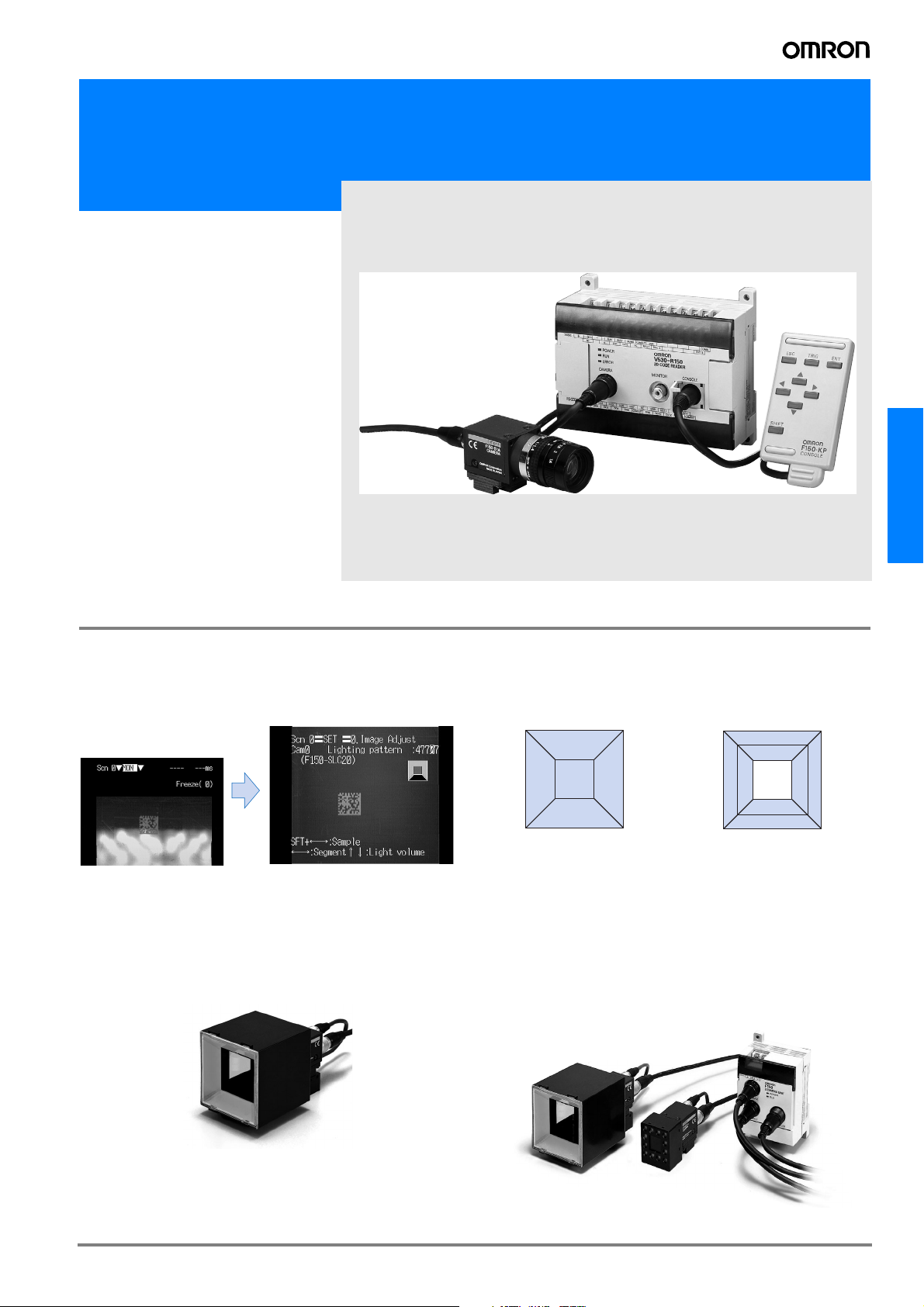
Intelligent Light Source
Versatile lighting control and a dome shape that minimizes external interference provide stable images for 2-dimensional code
reading.
Ring lighting Intelligent Light Source
Reduces the background effects of metal processed parts.
A Variety of Lighting Methods
The lighting direction and intensity can be changed. In addition,
coaxial lighting is available with the F150-SLC20. Optimal lighting methods can be set for a wide variety of workpieces.
F150-SLC20
(Field of vision: 20 mm)
The light intensity can be
set for each of five lighting
blocks, in eight steps.
2
135
Coaxial
lighting
4
Lighting Controlled from Menus
• The lighting block and intensity can be controlled from the Controller menu. Settings can be easily changed without having to touch
the light itself.
• Because light is handled as scene data, the lighting conditions can
be varied to match model changes on mixed-product lines.
• The Controller manages light settings numerically, for accurate
reproducibility.
Two-camera Unit
Two cameras can be switched by a single Controller.
F150-SLC50
(Field of vision: 50 mm)
The light intensity can be
set for each of eight lighting
blocks, in eight steps.
5
1
2684
3
7
C-75V530-R150E-3, EP-3
Page 2
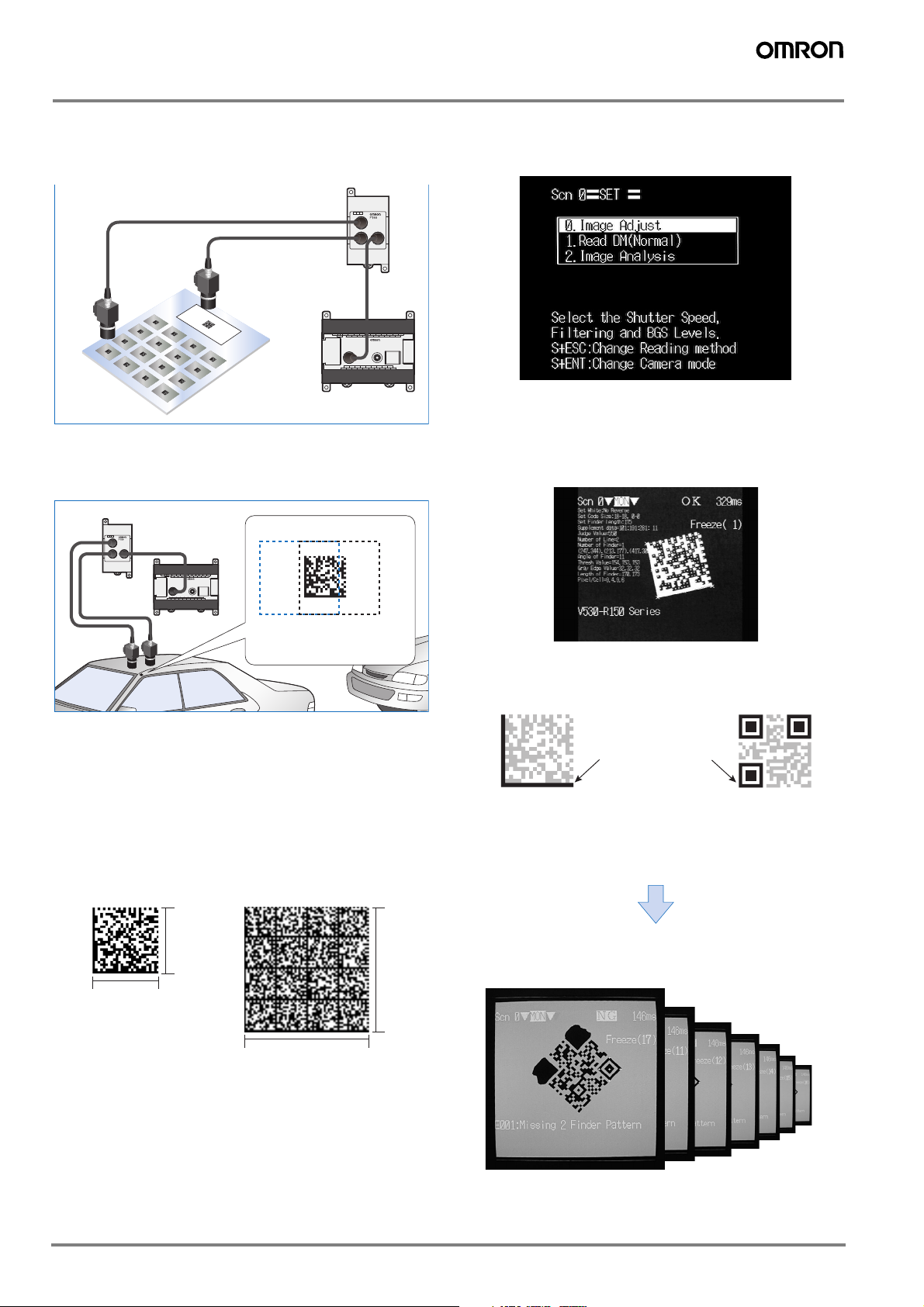
Application Example
Simultaneous single-product and lot management
Single products and lots can be managed simultaneously.
New Guidance Function for the Settings Display
The addition of a guidance function on the display greatly simplifies setting.
Camera 2
Camera 1
Electronic
components
Two-camera Unit
V530-R150
Controller
Greater positioning tolerance
For applications that cannot be covered by the field of view of
only one camera.
Two-camera Unit
V530-R150
Controller
Camera 1 field
ofvision (blue)
Positioning tolerance increased
by using two cameras to
expand the field of vision.
Camera 2 field
ofvision (black)
Easy-to-Read Analytical Data Format
See the reading status at a glance on the reading information
display.
The finder pattern, cell recognition, reading data, etc., can all be
viewed on the display.
Finder pattern (cutting symbol)
Use this pattern to detect the 2-dimensional code position. The
finder pattern is different for each code.
Compatible with Data Matrix Old Version
The V530-R150V3 Controller is also capable of reading the Data
Matrix Old Version. (See note.)
Note: Compatible with ECC000, 050, 080, 100, and 140.
Compatible with Data Matrix ECC200, with
Up to 64 × 64 Cells
To enable the use of more information, ECC200 codes with up to
64 × 64 cells (max. of 418 alphanumeric characters) can be
read.
26
64
26
Max. of 64
alphanumeric
characters.
64
Max. of 418
alphanumeric characters.
Finder pattern
Finder pattern
Data Matrix QR Code
Easy Image Analysis
The image analysis mode helps to detect the cause of marking
problems.
Store up to 24 Defect Images
Use the stored images to confirm defect types.
Stores up to
24 images
Note: Stored images are kept until the power is turned OFF.
C-76 Vision Sensors
Page 3
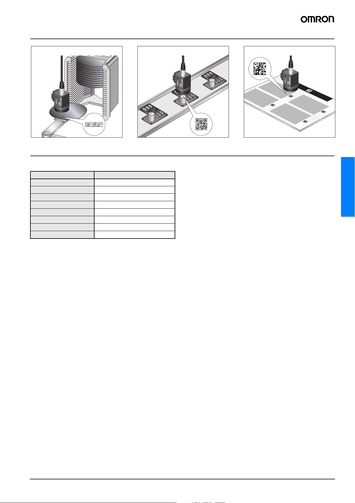
Applications
From batch processing level to
wafer level
Ordering Information
List of Models
Name Model No.
Controller
Console
Camera
Camera Cable (3 m)
Two-camera Unit
Monitor Cable (2 m)
Liquid Crystal Monitor
Video Monitor
V530-R150E-3, EP-3
F150-KP
F150-S1A
F150-VS
F150-A20
F150-VM
F150-M05L
F150-M09
From PCB level to component level
From sheet level to piece level
V530-R150E-3, EP-3
C-77V530-R150E-3, EP-3
Page 4
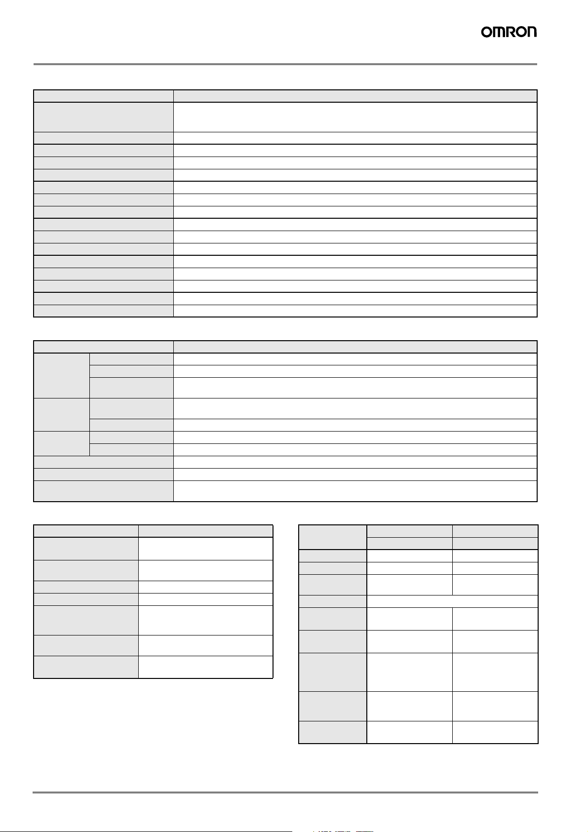
Specifications
Controller
Item V530-R150E-3, EP-3
Data Matrix ECC200: 10 × 10 to 64 × 64, 8 × 18, 8 × 32,12 × 26, 12 × 36,16 × 36,16 × 48
Readable codes
Readable direction
Number of pixels (resolution)
Number of connectable cameras
Number of scenes
Image memory function
Operation method
Processing method
Monitor interface
RS-232C I/F
Parallel I/O
Power supply voltage
Degree of protection
Current consumption
Ambient temperature/humidity
Weight
Camera
Data Matrix Old Ver. (ECC000, 050, 080, 100, 140): 9 × 9 to 25 × 25
QR Code (Model 1, 2): 21 × 21 to 41 × 41 (Version 1 to 6)
360°
512 (H) × 484 (V)
1 (Using F150-A20: 2 max.)
10
Maximum of 24 images stored.
Menu selectable
Gray
1 channel (over scan monitor)
1 channel
3 inputs and 9 outputs including control I/O points
20.4 to 26.4 VDC
IEC 60529: IP 20 (panel mounted)
Approx. 0.5 A
0 to 50°C/35% to 85% (with no condensation)
Approx. 390 g
Item F150-S1A
Picture element
Camera
Effective pixels
Shutter function
Lens
Mounting distance
Field of view
Light
Light source
Lighting method
Ambient temperature
Ambient humidity
Weight (camera only)
1/3” CCD
659 (H) × 494 (V)
Electronic frame shutter
Shutter speed: 1/100, 1/500, 1/2000, or 1/10000 sec (menu selectable)
F150-SLC20: 15 to 25 mmF150-SLC50: 16.5 to 26.5 mm
F150-SL20A: 61 to 71 mmF150-SL50A: 66 to 76 mm
F150-SLC20/SL20A: 20 × 20 mm, F150-SLC50/SL50A: 50 × 50 mm
F150-SLC20/50: Red LED/Green LED, F150-SL20A/50A: Red LED
Pulse (synchronized with camera shutter)
Operating: 0 to 50°C, storage: −25 to 60°C (with no icing or condensation)
Operating/Storage: 35% to 85% (with no condensation)
F150-ALC20: Approx. 280 g, F150-FLC50: Approx. 370 g,
F150-SL20A/50A: Approx. 135 g, F150-S1A: Approx. 80 g
Two-camera Unit Monitor
Item F150-A20
Number of connectable
2
cameras
Camera mode
Power supply voltage
Current consumption
Ambient temperature
Ambient humidity
Weight (2-camera unit
2-camera selectable
Single, independent (camera 0/1)
20.4 to 26.4 VDC
Approx. 0.3 A
Operating: 0 to 50°C
storage: −25 to 60°C
(with no icing or condensation)
Operating/Storage: 35% to 85%
(with no condensation)
Approx. 220 g
only)
Item
Size
Type
Resolution
Input signal
Power supply
voltage
Current con-
sumption
Ambient temperature
Ambient humidity
Weight (monitor
only)
Liquid Crystal Monitor Video Monitor
F150-M05L F150-M09
5.5 inches 9 inches
Liquid crystal color TFT CRT monochrome
320 × 240 dots 800 TV lines min. (at
NTSC composite video (1.0 V/75 Ω)
20.4 to 26.4 VDC 100 to 240 VAC
Approx. 700 mA Approx. 200 mA
Operating: 0 to 50°C
storage: −25 to 60°C
(with no icing or condensation)
Operating/Storage:
35% to 85%
(with no condensation)
Approx. 1 kg Approx. 4.5 kg
center)
(−15%, +10%)
Operating: −10 to 50°C
storage: −20 to 65°C
(with no icing or condensation)
10% to 90%
(with no condensation)
C-78 Vision Sensors
Page 5

System Configuration
Cameras
F150-SLC20 Camera with
Intelligent Light Source
(Field of vision: 20 mm)
F150-SLC50 Camera with
Intelligent Light Source
(Field of vision: 50 mm)
F150-SL20A Camera
with Light Source
(Field of vision: 20 mm)
F150-SL50A Camera
with Light Source
(Field of vision: 50 mm)
V530-R150E-3, EP-3
Controller
F150-VS Camera Cable
(3 m)
Camera Unit Cable (15 cm)
(Provided with the F150-A20)
Power
Supply
Synchronous Sensor
RS-232C
F150-VM Monitor
Cable (2 m)
F150-KP Console
(Cablelength: 2 m)
Programmable
Controller
Personal
Computer
V530-R150E-3, EP-3
F150-S1A Camera
Refer to page B-8 concerning the
use of this camera.
Note: If the field of vision doesnot
match the size of the targetobject
you can use an ordinary CCTV
lens and lighting.
F150-A20 Twocamera Unit
F150-VS Camera Cable
BNC Jack (Provided
with the F150-VM)
Monitors
F150-M05L Liquid
Crystal Monitor
(pin input)
F150-M09 Video
Monitor (BNC input)
Note: In addition to the F150-M05L and
F150-M09, NTSC monitors with external
video input terminals can be used.
C-79V530-R150E-3, EP-3
Page 6

Lighting Methods
Select the appropriate lighting method for the material of the marked object.
Back Lighting
Codes on transparent objects such as glass PCBs can be read
by detecting the contrast between transmitted and blocked light.
Applications: Transparent objects such as LCD glass
Oblique Lighting
Ring lighting close to the marked object
For codes inscribed with a laser maker onto PCBs and other relatively glossy surfaces, oblique lighting provides stable detection
by distinguishing between regular and diffuse reflected light.
Applications: Direct marking on PCBs and electronic parts
Camera
Marked object
(2-dimensional code)
Glass
Light source
Reflected Lighting
Ring Lighting
For codes printed onto paper or other light-diffusing objects, ring
lights can be used to illuminate the marked object. The difference in the reflection factors of the background and the marking
enables stable detection.
Applications: Paper labels and corrugated cardboard
Camera
Light source
Marked object
(2-dimensional code)
Paper
Camera
Light source
Marked object (2-dimensional code)
PCB
Coaxial Lighting
For codes marked directly onto wafers and other mirror-like surfaces, a stable image with few shadows from surface irregularities can be obtained from the marked object by using coaxial
lighting, because it detects only regular reflected light. (The surface of the object must be perpendicular to the optical axis.)
Applications: Mirror-like objects such as wafers
Camera
Light source
Marked object
(2-dimensional code)
Half mirror
Wafer
C-80 Vision Sensors
Page 7

Data Capacity
Data Matrix ECC200
The relation between matrix size (number of cells) and data
capacity is shown in the table below. In this example, the matrix
size is 12 × 12 cells.
QR Code Model 2
The relation between matrix size (number of cells) and data
capacity is shown in the table below. In this example, the matrix
size is 21 × 21 cells.
7 cells
12 cells
7 cells
7 cells
14 cells
Maximum data capacity
Alphanu-
meric
charac-
ters (up-
JIS8
per case
Matrix size
Num-
bers
12 cells
Maximum data capacity
Alphanu-
meric
charac-
Symbols
ters
Japa-
nese
Kanji
(Shift
JIS)
JIS8
Matrix size
(version)
Error
correc-
tion
7 cells
Num-
bers
only)
10 × 10
12 × 12
14 × 14
16 × 16
18 × 18
20 × 20
22 × 22
24 × 24
26 × 26
32 × 32
36 × 36
40 × 40
44 × 44
48 × 48
52 × 52
64 × 64
8 × 18
8 × 32
12 × 26
12 × 36
16 × 36
16 × 48
Note: 1. Maximum Data Capacity
The maximum amount of data that can be stored in a code varies with the code size. In other words, if there is a large amount of data to be stored, then the
code size must also be large. The maximum data capacity will also vary with the type of characters used. With a QR Code or Data Matrix, the numeric capacity (numbers only) is larger than the alpha numeric capacity (numbers and letters), which is in turn larger than the Japanese Kanji (Shift JIS) capacity.
The order and combinations of different characters also affects the data capacity.
2. The matrix size of a QR Code is indicated by the version. "Version 1" indicates that a QR Code contains (the minimum) 21 cells both horizontally and vertically.
The larger the version number, the larger the number of cells per side.
633---1
106513
16 10 9 3 6
24 16 14 5 10
36 25 22 8 16
44 31 28 10 20
60 43 38 14 28
72 52 46 17 34
88 64 57 21 42
12491813060
172 127 113 42 84
228 169 150 56 112
288 214 190 71 142
348 259 230 86 172
408 304 270 101 202
560 418 372 139 278
106513
20 13 12 4 8
32 22 20 7 14
44 31 28 10 20
64 46 41 15 30
98 72 64 23 47
21 × 21
(version 1)
25 × 25
(version 2)
29 × 29
(version 3)
33 × 33
(version 4)
37 × 37
(version 5)
41 × 41
(version 6)
L (7%) 41 25 17 10
M (15%)342014 8
Q (25%)271611 7
H (30%) 17 10 7 4
L (7%) 77 47 32 20
M (15%)63382616
Q (25%)48292012
H (30%)342014 8
L (7%) 127 77 53 32
M (15%) 101 61 42 26
Q (25%)77473220
H (30%)58352415
L (7%) 187 114 78 48
M (15%) 149 90 62 38
Q (25%) 111 67 46 28
H (30%)82503421
L (7%) 255 154 106 65
M (15%) 202 122 84 52
Q (25%) 144 87 60 37
H (30%) 106 64 44 27
L (7%) 322 195 134 82
M (15%) 255 154 106 65
Q (25%) 178 108 74 45
H (30%) 139 84 58 36
Japa-
nese
Kanji
(Shift
JIS)
V530-R150E-3, EP-3
C-81V530-R150E-3, EP-3
Page 8

Cameras with Light Source
Cameras with Intelligent Light Source
20-mm field of view
50-mm field of view
Note: These models consist of an F150-S1A Camera with Lens and Intelligent
Light Source.
Using the Camera with Intelligent Light Source or Camera
with Light Source
• The Lens has a fixed focus. Because there is a certain amount of
variation in the field of view and focus of each Lens, the mounting
distance must be adjusted each time the Lens or Camera is
replaced.
• The camera mounting distance is approximate. Use a mounting
method that allows the distance to be adjusted back and forth in
the direction of the 2-dimensional code.
F150-SLC20
F150-SLC50
Lenses
2-Dimensional Code Reader Distance vs. Field of
view
Mount the Camera at a distance that will provide accurate imaging of the 2-dimensional codes.
F150-SLC20 F150-SLC50
2-dimensional
code
Field of view (20 mm × 20 mm) Field of view (50 mm × 50 mm)
2-dimensional code
Camera distance:
15 to 25 mm
Camera distance:
16.5 to 26.5 mm
CCTV Lenses
CCTV Lenses
Model
3Z4S-LEB1214D-2 3Z4S-LEC1614A 3Z4S-LEB2514D 3Z4S-LEB5014A
42 dia.
30 dia.
30 dia.
48 dia.
Dimensions
37.3
48
Locking mecha-
50
33
Focus/iris locking mechanism
nism
Note: Refer to the following optical graph to select the Lens and Extension Tube according to the field of view and camera mounting distance being
used.
Extension Tubes
Model
Length
3Z4S-LE EX-C6
A set of six Extension Tubes that are 40, 20, 10,
5, 1, and 0.5 mm in length respectively.
C-82 Vision Sensors
Page 9

Optical Graph
15
355555
Point: Based on the necessary field of view and workpiece, select the Lens and Extension Tube to suit the working distance (WD).
Lengthening the Extension Tube lowers the brightness, and increasing distance WD increases the depth of field.
Note: Slight differences exist between cameras. When mounting the Lens, provide a means of adjusting the camera mounting distance. For example, to obtain a cam-
era mounting distance WD of about 30 mm with a field of view of 10 mm, mount a 5-mm Extension Tube to the 3Z4S-LEC1614A.
Optical Graph
50
0
450
400
350
300
250
200
Working distance (mm)
150
35 to 55
35
100
50
0
20
25
30
10
15
15
20
510
1
5
10
1
1
15
1
1
5
5
5
0203040
Field of view L (mm)
1
The values in the graph indicate the
Note:
3Z4S-LEB5014A
3Z4S-LEB2514D
3Z4S-LEC1614A
3Z4S-LEB1214D-2
3Z4S-LE@focal length
F-stop
length (in mm) of the Extension tubes.
Reading the Optical Graph
The X axis of the graph shows field of view L in millimeters, and
the Y axis shows the camera mounting distance A in millimeters.
The curves on the graph indicate different Lenses, and the “t”
values indicate the lengths of the Extension Tubes.
V530-R150E-3, EP-3
Working
distance WD
(mm)
Camera
Extension Tube
Lenses
Field of view L (mm)
C-83V530-R150E-3, EP-3
Page 10

Dimensions
Note: All units are in millimeters unless otherwise indicated.
2-Dimensional Code Reader
V530-R150E-3, V530-R150EP-3
Console
F150-KP
13
50
1.5
4.1
Four, 4.5 dia.
90
120
100
77.6
120
130
Camera
F150-SLC20
(Camera with F150-LTC20 Intelligent Light Source)
70
12 12
2.5
70
2.5
12 12
40
42.5
Mounting
dimensions
73 40
96.25
86.25
F150-SLC50
(Camera with F150-LTC50 Intelligent Light Source)
90
16
90
16
16
2.5
52.5
2.5
16
60
Mounting
dimensions
80 40
103.25
93.25
F150-S1A (Camera only)
14.5
15.5
25
40
37
11
Mounting
dimensions
48
8
(40)
1.5
30.5
16.75
31.25
2021.25
Two, M4 holes
with depth of 10
1/4-20UNC with
depth of 10
6.75
16.75
20
20
F150 connector
(85)
Two, M4 holes
with depth of 10
1/4-20UNC with
depth of 10
6.75
(85)
16.75
Two, M4 holes
with depth of 10
1/4-20UNC with
depth of 10
6.75
31
50
F150 light
connector
12 dia.
2000
Two-camera Unit
F150-A20
Mounting holes
100±0.2
Two,
56±0.2
M4
Liquid Crystal Monitor
F150-M05L
(100)
185
174
Panel cut diagram
Video Monitor
F150-M09
233
143
5
23
66
100
56
Allowable panel thickness for mounting:
1.6 to 4.8
(145)
132
143
(5.5)
F150-VM Monitor Cable
Tolerance: ±1 mm
42.2
Dimensions inside parentheses ( ) are reference values.
+0.5mm
175.5
0
222
190
50
87
5
50
3.3
Two, 4.5 dia.
(mounting holes)
(46 max)
Mounting bracket
(155)
50 min
+0.5mm
133.5
0
250
160
22
12.5
10
90 110
C-84 Vision Sensors
Page 11

V530-R150E-3, EP-3
C-85V530-R150E-3, EP-3
Page 12

ALL DIMENSIONS SHOWN ARE IN MILLIMETERS.
To convert millimeters into inches, multiply by 0.03937. To convert grams into ounces, multiply by 0.03527.
Cat. No. Q12E-EN-01
In the interest of product improvement, specifications are subject to change without notice.
C-86 Vision Sensors
 Loading...