

Page 1

Z334-E1-01A
Cat. No.
Fixed Laser-Type
Barcode Reader
User’s Manual
V500-R2 Series
Page 2

Introduction
Thank you for purchasing the OMRON V500-R2 series.
This manual describes the functions, performance, and application
methods of the V500-R2 series.
This manual is intended for personnel with knowledge of electrical
systems. Be sure to read and understand this manual thoroughly before
using the product, and keep this manual in an easily accessible location
for quick reference when required.
Page 3

Introduction
Introduction Section 1 Section 2 Section 3 Section 4 Section 5 Appendix
Introduc- Section 1 Section 2 Section 3 Section 4
Introduction
Section 1
Section 2
Section 3
Section 4
Section 5
READ AND UNDERSTAND THIS DOCUMENT (Be sure to read this.)
Product Overview
Wiring and Installation
Function Explanation
Setting Method
Example of System Configuration
Section 6
Appendix
Bar Code Reader
User’s Manual
V500-R2 series
Page 4

Introduction
Introduction
READ AND UNDERSTAND THIS DOCUMENT
Please read and understand this document before using the products. Please consult your OMRON
representative if you have any questions or comments.
WARRANTY
OMRON’s exclusive warranty is that the products are free from defects in materials and workmanship for
a period of one year (or other period if specified) from date of sale by OMRON.
OMRON MAKES NO WARRANTY OR REPRESENTATION, EXPRESS OR IMPLIED, REGARDING
NON-INFRINGEMENT, MERCHANTABILITY, OR FITNESS FOR PARTICULAR PURPOSE OF THE
PRODUCTS. ANY BUYER OR USER ACKNOWLEDGES THAT THE BUYER OR USER ALONE HAS
DETERMINED THAT THE PRODUCTS WILL SUITABLY MEET THE REQUIREMENTS OF THEIR
INTENDED USE. OMRON DISCLAIMS ALL OTHER WARRANTIES, EXPRESS OR IMPLIED.
LIMITATIONS OF LIABILITY
OMRON SHALL NOT BE RESPONSIBLE FOR SPECIAL, INDIRECT, OR CONSEQUENTIAL
DAMAGES, LOSS OF PROFITS OR COMMERCIAL LOSS IN ANY WAY CONNECTED WITH THE
PRODUCTS, WHETHER SUCH CLAIM IS BASED ON CONTRACT, WARRANTY, NEGLIGENCE, OR
STRICT LIABILITY.
In no event shall responsibility of OMRON for any act exceed the individual price of the product on which
liability is asserted.
IN NO EVENT SHALL OMRON BE RESPONSIBLE FOR WARRANTY, REPAIR, OR OTHER CLAIMS
REGARDING THE PRODUCTS UNLESS OMRON’S ANALYSIS CONFIRMS THAT THE PRODUCTS
WERE PROPERLY HANDLED, STORED, INSTALLED, AND MAINTAINED AND NOT SUBJECT TO
CONTAMINATION, ABUSE, MISUSE, OR INAPPROPRIATE MODIFICATION OR REPAIR.
SUITABILITY FOR USE
THE PRODUCTS CONTAINED IN THIS DOCUMENT ARE NOT SAFETY RATED. THEY ARE NOT
DESIGNED OR RATED FOR ENSURING SAFETY OF PERSONS, AND SHOULD NOT BE RELIED
UPON AS A SAFETY COMPONENT OR PROTECTIVE DEVICE FOR SUCH PURPOSES. Please refer
to separate catalogs for OMRON's safety rated products.
OMRON shall not be responsible for conformity with any standards, codes, or regulations that apply to
the combination of products in the customer’s application or use of the product.
At the customer’s request, OMRON will provide applicab le third party certification documents identifying
ratings and limitations of use that apply to the products. This information by itself is not sufficient for a
complete determination of the suitability of the products in combination with the end product, machine,
system, or other application or use.
The following are some examples of applications for which particular attention must be given. This is not
intended to be an exhaustive list of all possible uses of the products, nor is it intended to imply that the
uses listed may be suitable for the products:
• Outdoor use, uses involving potential chemical contamination or electrical interference, or conditions or
uses not described in this document.
V500-R2 series
2
User’s Manual
Page 5

Introduction
• Nuclear energy control systems, combustion systems, railroad systems, aviation systems, medical
equipment, amusement machines, vehicles, safety equipment, and installations subject to separate
industry or government regulations.
• Systems, machines, and equipment that could present a risk to life or property.
Please know and observe all prohibitions of use applicable to the products.
NEVER USE THE PRODUCTS FOR AN APPLICATION INVOLVING SERIOUS RISK TO LIFE OR
PROPERTY WITHOUT ENSURING THAT THE SYSTEM AS A WHOLE HAS BEEN DESIGNED TO
ADDRESS THE RISKS, AND THAT THE OMRON PRODUCT IS PROPERLY RATED AND INSTALLED
FOR THE INTENDED USE WITHIN THE OVERALL EQUIPMENT OR SYSTEM.
PERFORMANCE DATA
Performance data given in this document is provided as a guide for the user in determining suitability and
does not constitute a warranty. It may represent the result of OMRON’s test conditions, and the users
must correlate it to actual application requirements. Actual performance is subject to the OMRON
Warranty and Limitations of Liability.
CHANGE IN SPECIFICATIONS
Product specifications and accessories may be changed at any time based on improvements and other
reasons.
Introduction
It is our practice to change model numbers when published ratings or features are changed, or when
significant construction changes are made. However, some specifications of the product may be
changed without any notice. When in doubt, special model numbers may be assigned to fix or establish
key specifications for your application on your request. Please consult with your OMRON representative
at any time to confirm actual specifications of purchased products.
DIMENSIONS AND WEIGHTS
Dimensions and weights are nominal and are not to be used for manufacturing purposes, even when
tolerances are shown.
ERRORS AND OMISSIONS
The information in this document has been carefully checked and is believed to be accurate; however, no
responsibility is assumed for clerical, typographical, or proofreading errors, or omissions.
PROGRAMMABLE PRODUCTS
OMRON shall not be responsible for the user’s programming of a programmable product, or any
consequence thereof.
COPYRIGHT AND COPY PERMISSION
This document shall not be copied for sales or promotions without permission.
This document is protected by copyright and is intended solely for use in conjunction with the product.
Please notify us before copying or reproducing this document in any manner, for any other purpose. If
copying or transmitting this document to another, please copy or transmit it in its entirety.
V500-R2 series
User’s Manual
3
Page 6

Introduction
Introduction
Meanings of Signal Words
In this manual, precautions are indicated using the following symbols and signal words to ensure safe
use of the V500-R2 series. The precautions indicated by these symbols and signal words are important
for safety and must be observed.
Indicates a potentially hazardous situation which, if not avoided, will result in
WARNING
minor or moderate injury, or may result in serious injury or death. Additionally
there may be significant property damage.
Indicates a potentially hazardous situation which, if not avoided, may result in
minor or moderate injury or in property damage.
Meanings of Alert Symbols
Indicates the possibility of laser radiation.
Indicates prohibition when there is a risk of minor injury from electrical shock or other
source if the product is disassembled.
Indicates instruction for the user to always connect the ground wire.
V500-R2 series
4
User’s Manual
Page 7

For the Safety Use of Laser Products
• Warning display
WARNING
Avoid eye exposure to direct or scattered radiation reflected by a mirror
surface.
Laser beam emitted from a laser has high power density and may become
blind when the beam is directed into eyes.
Do not disassemble this bar code reader.
Laser beam may be scattered around when it is disassembled.
• Caution display
Introduction
Introduction
Caution-Use of controls or adjustments or performance of procedures other
than those specifies herein may result in hazardous radiation exposure.
This Bar Code Reader uses a laser as the light source.
Lasers are classified on IEC standard (IEC 60825-1).
V500-R2CF
Wavelength 650 nm
Peak power 1 mW max.
Classification 2
Labeling on Laser Use
This Bar Code Reader has the following WARNING Label.
This Bar Code Reader is compliant with IEC 60825 and the U.S. FDA (Food and Drug Administration)
laser regulations.
V500-R2 series
User’s Manual
5
Page 8

Introduction
Introduction
Usage
• Use laser enclosure device to prevent specular object from reflecting laser beam.
When used without an enclosure, be sure to avoid a laser path from eye level.
• Although the safety distance (NOHD) is approximately 1 m; it is advisable, however, to terminate the laser on its path
if possible. Nonreflective, flatting material is recommendable for termination.
• Wear protective glassed to protect against laser light during set up and adjustment.
Outline of IEC 60825-1 Standard
The following are the safety measures to be taken by the user for each type of laser equipment.
Classification
Required items
Remote interlock Not required Connect to room or door circuits.
Key control Not required Remove key when not in use.
Beam attenuator Not required When in use prevents inadvertent
Emission indicator
device
Warning signs Not required Follow precautions on warning
Beam path Not required Terminate beam at end of useful length.
Specular reflection Not required Prevent unintentional reflections.
Eye protection Not required Required if engineering and
Protective clothing Not required Sometimes
Training Not required Required for all operator and maintenance personnel.
* With respect to the requirements of remote interlock connector, key control, beam attenuator, emission indicator
device, and eye protection, Class 3B laser products not exceeding five times the AEL of Class 2 in the wavelength
range of 400 nm to 700 nm are to be treated as Class 3A laser products.
Class 1 Class 2 Class 3A Class 3B* Class 4
exposure.
Not required Indicates laser is energized.
signs.
administrative procedures not
practicable and MPE exceeded.
Specific
required.
requirements.
V500-R2 series
6
User’s Manual
Page 9

Precautions for Safe Use
Observe the following precautions to ensure safe use of the product.
1. Installation Environment
• Do not use the product in environments containing flammable or explosive gases.
• Do not use the product in environments containing corrosive or combustible gases.
• Do not use the product in environments containing dust, salt, or metallic powders.
• Do not use the product in environments containing droplets, water or mist, oil or
chemical agents.
• Do not use the product in environments that may be affected by a CRT's flashing or
other ambient light.
• Do not install or use the product outdoors.
• For the purpose of ensuring safe operation and maintenance, do not install the
product close to high-voltage devices or electrically powered devices.
Introduction
Introduction
2. Power Supply and Wiring
• To assure noise and insulation resistance, be sure to use S8VS-01505 (made by
OMRON) as a driving power supply.
• Do not connect a voltage or AC power supply that has a voltage exceeding the rating
voltage (5 V+/-10%).
• Avoid reverse connection of power supply. Do not short circuit a load on OK/NG
output signal (open collector).
• Avoid applying a load that exceeds the rating.
• Be sure to turn the power OFF before connecting or disconnecting a cable.
Connecting or disconnecting a cable while the power is ON may cause failure.
• Connect different cables from high-voltage or power cable s to th e pr od uc t. If th e
same cable or duct is used, electromagnetic induction may result, which may result in
malfunction or damage.
• Tighten the fixing screws at the torque specified in this manual.
3. Communication with Upper Equipment
• Check that the product has started up, and then start communication with upper
equipment.
• Indefinite signals may be generated from the upper interface while the product starts
up. Clear the receive buffer of the devices before starting initial operation.
V500-R2 series
User’s Manual
7
Page 10

Introduction
Introduction
4. Other
• Do not use the product in a safety circuit for nuclear or life-support systems.
• Never attempt to disassemble, repair, modify, deform by applying pressure, or burn
the product.
• Dispose of the product as industrial waste.
• If the product becomes extremely hot, or abnormal odors or smoke are emitted, stop
using the product immediately, turn the power OFF, and consult with your OMRON
representative.
5. Regulations and standards
This product complies with the following standards.
Laser safety standards: IEC 60825-1:2007 (2nd Edition) Class 2
JIS C 6802 Class 2
EN Standard (CE mark): EN55022/EN55024
V500-R2 series
8
User’s Manual
Page 11

Introduction
Precautions for Correct Use
Always observe the following precautions to prevent operation failures, malfunctions, and adverse effects
on performance and equipment.
1. Installation location
The product must not be installed in a place:
• where ambient temperature is outside the range defined in the specifications,
• where a rapid temperature change (dew condensation) occurs,
• where ambient humidity is outside the range defined in the specifications,
• where direct vibration or shock may affect the product,
• where exposed to intense ambient light (laser, arc welding, or UV light),
• where exposed to direct sunlight or heat from heating appliances, and
• where a strong magnetic or electric field exists.
Introduction
Because of the protection rating described in the manual, avoid using
locations containing:
• corrosive or combustible gases,
• dust, salt, or metallic powders,
• droplets, water mist, oil or chemical agents.
2. Power supply, connection, and wiring
• Be sure to use S8VS-01505 (made by OMRON) as a driving power supply.
• Do not install the product in a location where a high-voltage device is inst alled.
• Be sure to user the supplied insulation board to assure the noise resistance.
• After connecting the cables, check that the correct power supply is used, that there is
no load short-circuiting or other inappropriate co nnections, and that the load current is
correct before turning the power ON. Faulty wiring may be the cause of failure.
• Use a wrist strap or other similar device to avoid electrostatic char ge when you touch
terminals and signal lines within a connector, and to avoid damage due to static
electricity.
• Try to keep the length of the power cable to a minimum (less than 3 m).
3. Installation
• When installing this code reader , use the provided insulating plate and mounting
bracket.
• Use the provided screws for installation, an d tighten to the torque specified in these
instructions.
• Incline the bar code reader about 15° to read the target bar code.
• Do not apply stress on the cable when mounting and using.
V500-R2 series
User’s Manual
9
Page 12

Introduction
Introduction
• V500-R2 series are precision instruments. Be careful not to give an impact or make
them fall.
• Do not hold the sensor only by the cable part when moving the sensor. A sensor body
part will be damaged.
• Distance and angle allowed to read differs according the bar code. Check if the used
bar code can be read actually, before mounting.
4. Timing input with photo-electronic sensor
When taking timing with the photo-electronic sensor , mount the bar co de reader so that
the footlight beam of the photo-electronic sensor does not spot directly on the reading
window of the bar code reader or on the bar code.
Bar code
Photo-electronic sensor
Footlight beam of the photo-electronic sensor spots
on the reading window of the bar code reader.
Footlight beam of the photoelectronic sensor spots on the
bar code.
5. Influence of reflective objects
When there is any reflective object such as metal or mirror surface on the bar code
beam-scanning surface, reading character may be deteriorate. Cover the reflective
object with something or change the bar code position to avoid influence.
V500-R2 series
10
User’s Manual
Page 13

Introduction
6. Mutual interference
When mounting the bar code readers side-by-side, laser beams may interfere reading
each other. The bar code readers should be placed far enough not to affect reading.
Bar code
Introduction
7. Bar code label
• The height of the bar code should be more than the luster scan width (max. 10 mm)
and use a label considering attaching error.
• When reading bar code, margin is necessary on the both sides of the bar code. Set
the label so that margin parts do not hide. A space of one character or more and 2.5
mm or more is necessary of both right and left side of the label. (Rough standard: 12
or 13 times or more of the narrow bar width)
Bar code
Margin
Width
Label
(Paper which a bar code is printed on)
Narrow bar
(Slim lines)
Margin
Height
8. To improve reading reliability
• When the digit is determined, designate the digit to use the bar code.
• Use the modulus check (addition of check digit).
• Bar codes other than the reading object should be set to reading prohibition.
p.62
9. Maintenance and check
• Check for any dust or dirt on the reading window regularly. When it is dirty, wipe with
a dry, soft and clean cloth. Do not use solutions such as thinner.
• Handle with care, not to apply strong shock such as dropping.
V500-R2 series
User’s Manual
11
Page 14
Introduction
Introduction
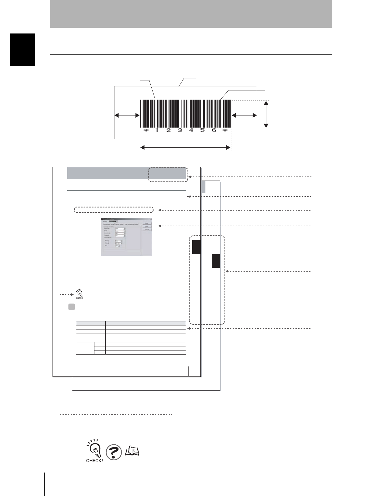
How to Use This Manual
How to Use This Manual
In this manual, each part of the bar code is described as follows.
Label
Bar code
(Paper which a bar code is printed on)
Narrow bar
(Slim lines)
Margin
Margin
Height
Width
For a page format
Section 4
System Settings
Creating Setting Files Using the 2DCR Configear
Creates the data setting file for loading set data to the Handheld 2D Code Reader.
Make the settings for the communications conditions, functions, and display conversion.
Se lect Setting Reader - Create Data... from the menu.
The following window for creating the setting data file will be displayed.
System Settings
Section 4
Section 4 Creating Setting Files Using the 2DCR Configear
Section title
Outline
Move to the setting screen.
Screen display
■ Open
Opens the previously created data setting file for editing.
The [Receive (R
Reader and edit it.
■ Save
Saves the created data setting file.
)] function can be used to open the data file downloaded from the Code
To save data to the Memory Card, create a folder with the name SETTINGS, and save. If the data is
saved to a folder other than “SETTINGS”, it cannot be uploaded.
Communication Settings
The settings shown in the following table are set in the Communica tion Settings Tab
Page in the Create Setting Data Window.
Setting item Settings
Baud Rate
Parity
Data Length
Stop Bit
Header/Footer Prefix
The default settings are indicated with an asterisk.
*
, 19,200, or 38,400
9,600
*
None
, odd, or even
8 bits
77 bits or
*
or 2 bits
1sbit
None*, 02 <STX>, or 1B <ESC>
Suffix
ETX, 0A LF,
FCS
ON or
OFF
0D CR
*
*
*
, or 0D0A CR+LF
V500-R2 series
User’s Manual
65
V500-R2 series
User’s Manual
Procedure and additional explanations
Information useful during the operation and reference
pages are provided here with special marks to indicate
the kind of information being provided.
Section 4 Uploading from the Memory Card
Index label
Provides the section number
and subject matter. Can be
used to immediately open the
desired page.
Describes the settings.
69
V500-R2 series
12
User’s Manual
*This page does not actually exist in this manual.
Page 15

Visual Aids
Introduction
Introduction
Indicates points that are important in using product functions or in application procedures.
Indicates page numbers providing related information.
Indicates helpful information when a problem occurs and explanations of technical terms.
Visual Aids
V500-R2 series
User’s Manual
13
Page 16

Introduction Contents
Introduction
Contents
Introduction
Meanings of Signal Words 4
Meanings of Alert Symbols 4
For the Safety Use of Laser Products 5
Precautions for Safe Use 7
Precautions for Correct Use 9
How to Use This Manual 12
Visual Aids 13
Contents 14
Section 1 Product Overview 17
Features 18
Product Composition 20
Part Names 21
Rating/Performance 22
Usage Flow Chart 27
Section 2 Wiring and Installation 29
Wiring 30
Installation 33
Section 3 Function Explanation 35
Explanation of Reading System 36
Operation Flow Chart 37
Communication Data Format 45
Test Reading Function 48
V500-R2 series
14
User’s Manual
Page 17

Introduction
Section 4 Setting Method 51
How to Use Menu Sheet/Command 52
Menu Sheet/Command List 56
Section 5 Example of System Configuration 97
Example of Connection with a PC 98
Example of Connection with Programmable Controller (CS1) 99
Example of Multi-drop Connection 102
How to Use Command Link Unit V700-L12 106
Introduction Contents
Section 6 Appendix 123
External Dimension 124
Troubleshooting 129
ASCII Code Table 130
Explanation of Terms 131
Corresponding Bar Code List 136
Revision History 140
V500-R2 series
User’s Manual
15
Page 18

Introduction Contents
Introduction
MEMO
V500-R2 series
16
User’s Manual
Page 19

Section 1
Product Overview
This section explains about features and rating/performance of this bar code
reader.
Features 18
Product Composition 20
Part Names 21
Rating/Performance 22
Usage Flow Chart 27
Section 1 Product Overview
V500-R2 series
User’s Manual
17
Page 20

Section 1
Product Overview
Features
Section 1 Features
A bar code reader is a device to read a bar code attached on a product and transfer the
information to upper equipment.
Various types of information can be managed efficiently by using it combining with PC and
programmable controllers.
Problems on site Bar code solution!
Work data are recorded on papers.
> Reading and writing mistakes and
distribution of workers exist.
> Formats are difficult to learn because various
kinds are produced in small numbers.
Cost should be as cheap as possible as
the product price is low.
Register product numbers and setting on PC
and programmable controllers beforehand and
import a product number only by reading a bar
code. Input mistake or distribution of workers
are eliminated.
Cost is very low by only attaching a printed bar
code label.
Ultra-compact design
Optimum for the assembly to each device
34.5 mm
17 mm
29 mm
Easy installation
Easy to read by pressing the SCAN button and know the reading rate with LED
illumination and buzzer sound in real time.
As reading position is easy to check at site before connecting with upper equipment,
installation work and maintenance work hour can be greatly reduced.
p.48
Simple function setting
You can either set the function by reading a menu sheet or by inputting a command on
the upper equipment. You can select the setting method according to the condition.
p.52
V500-R2 series
18
User’s Manual
Page 21

Section 1
Product Overview
Perfect reading performance
High speed reading with 1000 scan/sec. realized high reliability and wide reading
distance of 70 mm to 330 mm (in case of narrow bar width 1.0 mm).
p.24
Easy multi-drop
Connect communication link unit V700-L12 to collect read data from plural bar code
readers (max. 31) for one set of upper equipment.
p.102
Communication link
unit
V700-L12
Communication
Upper
equipment
converter
K3SC
Bar code reader
V500-R2 series
Section 1 Features
Max. 31 sets
V500-R2 series
User’s Manual
19
Page 22

Section 1
Product Overview
Product Composition
Section 1 Product Composition
The bar code reader is used by connecting with upper equipment such as PC and
programmable controllers.
The upper equipment receives information which the bar code reader reads and refers with
the registered information and records.
V500-R2 series
Tip of the cable is a connector. Use an appropriate connecting cable according to the
upper equipment.
PC (PC/AT compatible)
p.98
Power supply (5 VDC)
Recommended:
S8VS-01505
Programmable controller
Bar code reader
V500-R2 series
Cable for connecting with PC/AT compatible
V509-W011D
Programmable controller made by OMRON
Connecting cable
V509-W011
p.99
V500-R2 series
20
User’s Manual
Page 23

Part Names
Section 1
Product Overview
Front side
Back side
Section 1 Part Names
Main cable
Laser alarm label
Reading window
Laser beam radiates from here
READ OK LED
Illuminates when read correctly.
SCAN button
Press it once to read once.
V500-R2 series
User’s Manual
21
Page 24

Section 1
Product Overview
Rating/Performance
Section 1 Rating/Performance
Model V500-R2CF
Direction of view Front view
Applicable
codes
Reading
performance
(*)
Interface Communication
Function setting method Menu sheet reading method or host command method
Functional
specifications
Power supply
specification
General specification
Bar code WPC(JAN/EAN/UPC), Codabar(NW-7), ITF,Industrial2of5(STF),
Code39, Code93, Code128, GS1-128(EAN-128), GS1-Databar(RSS-
14), GS1-Databar Limited(RSS Limited), GS1-Databar Expanded(RSS
Expanded)
Number of reading
digits
Minimum resolution Bar code: 0.15 mm
Contrast (PCS) 0.45 or more (white reflectance 70 % or more)
Reading distance 60 to 270 mm (At narrow bar: 0.5 mm)
Reading angle Within 40° (Including margins at left and right sides)
Skew angle (α) ±60°(However, exclude from 10° upper side to 7° lower side)
Pitch angle (β) ±30°
Tilt angle (γ) ±25°
Reading of bar codes
on curved surfaces (R)
Light source Red laser diode (Wave length: 650 nm)
Light output 1.0m W or less (Correspond to JIS class 2)
Scan type Raster scan
Number of scan 1000 scan/sec.
specification
OK/NG outputs NPN open collector outp ut (cable work required)
Reading trigger External trigger (Transistor input)
OK/NG signals OK signal is turned on to indicate a successful read
Indication LED OK LED (green) illuminates to indicate a successful read
Buzzer Notifies a successful reading with a buzzer sound (Muting available)
Power voltage 4.5 to 5.5 VDC
Consumption current During operation: 500 mA or less; during standby: 150 mA or less
Inrush current 2.0 A MAX
No upper limit (depends on bar width and reading distance)
R 20mm (UPC 12 digit)
RS-232C
Trigger by command (RS-232C)
Trigger a test reading by pressing the SCAN button on the product
NG signal is turned on to indicate a successful read of a non-registered
label
V500-R2 series
22
User’s Manual
Page 25

Section 1
Product Overview
Environmental
specifications
Degree of protection IP54 (IEC60529)
Weight Main unit only Approximately 80 g
Dimensions Main unit Approximately 29(W) × 34.5(D) × 17(H)mm
Input/output connector Round DIN connector
Code length Approximately 1.5 m
Minimum bending radius of cord Approximately 23 mm
Accessories Operation manual, menu sheet, mounting bracket, insulation plate,
Material, Color Upper side case Die-cast magnesium, black
* Unless otherwise specified, use a JAN x1 , MRD 63% or higher (PCS = 0.9 or higher) barcode with a pitch angle
α =0°, a skew angle β =15°, a tilt angle
Ambient temperature
range
Ambient humidity range At operation and storage: 20 to 85% RH (with no icing or condensation)
Ambient atmosphere No corrosive gases
Ambient light Fluorescent lamp: 4,000lx or less, Sunlight: 80,000lx or less
Vibration resistance 10 to 150 Hz, half amplitude 0.35 mm, 3 directions (X/Y/Z), 8 minutes
Including accessories Approximately 190 g (including mounting bracket, insulation plate and
Packaged weight Approximately 270 g (including packing carton)
Packing carton Approximately 245(W) × 110(D) × 40(H)mm
Pront panel PC, black
Labe PET
Reading window PMMA, transparent
Cable Polyvinyl chloride (PVC), black
Insulation plate ABS, black
Mounting bracket SUS304, silver
At operation: 0 to + 45°C; At storage: -20 to + 60°C
each 10 times
screws)
M3 × 6 screw (two), M3 × 8 screws (one), M5 × 10 screws (two)
γ =0°, and a curvature R = ∞.
Section 1 Rating/Performance
V500-R2 series
User’s Manual
23
Page 26

Section 1
Product Overview
Number of reading range performance
Explained with examples of following conditions:
Section 1 Rating/Performance
• Contrast: MRD 63 % (PCS = 0.9)
• Bar code: CODE39
• Installation condition:Pitch angle α = 0°, skew angle β = 15°
Tilt angle γ = 0°, curvature R = ∞
Reading distance (Unit: mm)
0100200300400
40°
Narrow bar width
Narrow bar width
A 0.15 mm 70 to 140 mm
B 0.25 mm 60 to 200 mm
C 0.5 mm 60 to 270 mm
D 1.0 mm 70 to 330 mm
Reading distance
(*1)
A
B
C
D
*1 Distance from the end of the case.
V500-R2 series
24
User’s Manual
Page 27

Reading angle performance
Section 1
Product Overview
Pitch angle
In the following conditions, readable up to α = 30° on either side.
• Bar code: Resolution = 0.25 mm, CODE39 (9 digits), PCS = 0.9
• Reading distance: 11 0 mm fro m the case end
• Installation condition: Skew angle β = 15°, tilt angle γ = 0°, curvature R = ∞
−α
+α
Section 1 Rating/Performance
Skew angle
In the following conditions, readable up to β = ± 60°. However, range from β = -8° to +10° is
an area difficult to read due to regular reflection.
• Bar code: Resolution = 0.25 mm, CODE39 (9 digits), PCS = 0.9
• Reading distance: 110 mm from the case en d
• Installation condition: Pitch angle α = 0°, tilt angle γ = 0°, curvature R = ∞
−β
+β
V500-R2 series
User’s Manual
25
Page 28

Section 1
Product Overview
Tilt angle
Generally, a tilt angle is not specified, because it differs according to the bar code
Section 1 Rating/Performance
height.
Scan all the bar code with the laser.
Curvature
In case of the following conditions, the bar code of 8-digit EAN, curvature range 15 mm
or more and 13-digit EAN, curvature range 20 mm or more can be read.
• Bar code: Resolution = 0.26 mm, EAN, PCS = 0.9
• Reading distance: 110 mm from the case end
• Installation condition: Pitch angle α = 0°, skew angle β = 15°, tilt angle γ = 0°
V500-R2 series
26
User’s Manual
Page 29

Usage Flow Chart
Section 1
Product Overview
Examination of the bar code beforehand, installation, and introduction flow chart is as shown below.
Examination
beforehand
Check the type, width, height and numbers of digit of bar codes.
p.22 Rating/Performance
p.136 Corresponding Bar Code List
Wiring.
Connection
p.30 Wiring
Connect peripheral equipment.
p.97 Example of System Configuration
Section 1 Usage Flow Chart
Turn on the power switch.
Check that the bar code in subject can be read.
p.48 Test Reading Function
Preparation
Investigate the reading timing and moving speed.
p.37 Operation Flow Chart
Set the reading condition corresponding to the purpose.
p.56 Menu Sheet/Command List
V500-R2 series
User’s Manual
27
Page 30

Section 1
Product Overview
Section 1 Usage Flow Chart
Install.
Execution of reading
of using
p.33 Installation
Installation -
Test in the actual usage envir on me n t.
p.48 Test Reading Function
Execute reading.
Applied way
Read only the registered bar code.
p.79 Setting for label registration
In case of trouble:
A bar code cannot be read correctly.
p.129 Troubleshooting
I can't understand the operation flow.
p.37 Operation Flow Chart
V500-R2 series
28
User’s Manual
I don't know the communication specification.
p.45 Communication Data Format
Page 31

Section 2
Wiring and Installation
This section explains about the wiring method and installation method of the
bar code reader.
Wiring 30
Installation 33
Section 2 Wiring and Installation
V500-R2 series
User’s Manual
29
Page 32

Section 2 Wiring
Section 2
Wiring and Installation
Wiring
• Extension length of the RS-232C line (SD, RD, and SG) should be up to 15 m.
• Wiring should avoid approaching to a high-power heavy electric current wire.
• Turn off the power switch before connecting or disconnecting a connector.
• To assure noise and insulation resistance, be sure to use S8VS-01505 (made by OMRON) as a driving power
supply.
• Do not connect a voltage or AC power supply that has a voltage exceeding the rating voltage (5 V+/-10%).
• Avoid reverse connection of power supply. Do not short circuit a load on OK/NG output signal (open
collector).
Wiring diagram
V500-R2 series
(Pin alignment)
Connector part (DIN: 8P plug)
Made by Hosiden Corporation
TCP1394-715267 (TypeA)
Wire color Pin No. Signal name Function
Green 1 SD Transmission data
White 2 RD Received data
Gray 3 RS Transmission request
Blue 4 CS Transmission allowed
Brown 5 TRIG External trigger signal
- 6 NC Not connected
Black 7 S.GND 0 V
Red 8 VCC Power supply
Yellow - (Note) OK READ OK output External
Orange - (Note) NG READ NG output External
Reader
Signal direction
Upper equipment
External
External
Connection with upper equipment p.98, p.99
The OK and NG output lines are not connected to the DIN 8-pin connector. To use the OK and NG
outputs, cut the cables.
V500-R2 series
30
User’s Manual
Page 33

Wiring and Installation
When you make a connection cable, use the following connectors.
Recommended parts for the connector
Usage Manufacturer Model
For cable relay Hosiden Corporation TCS8587-0170477
For panel installation 2 Hosiden Corporation TCS1080-0120177
Section 2
Logic of external trigger signal can be selected.
Positive logic
(HIGH active)
Negative logic
(LOW active)
You can select the output logic of READ OK and READ NG signal.
Trigger ON
Trigger ON
Setting method p.57
Power supply
Recommended parts for the power supply
Manufacturer Model
OMRON Corporation S8VS-01505
Input/output circuit
Input circuit for the external trigger signal (V500-R2 series)
Vcc
Section 2 Wiring
External trigger signal
Von/off
Item
Terminal voltage Von when a
transistor is turned on
Terminal voltage Voff when a
transistor is turned off
TRIG
SG
Minimum
value
0 V 0.8 V
2.0 V 3.3 V
Maximum
Internal
circuit
value
V500-R2 series
User’s Manual
31
Page 34

Section 2
Wiring and Installation
READ OK/NG signal output circuit
Section 2 Wiring
OK/NG
Internal
circuit
SG
Item Specification
Output system NPN open collector
Rated load 24 VDC 30 mA
Leak current at OFF 0.5 mA or less
Residual voltage at ON 1 V or less
Cable specification
• Shape: Straight cable
• Diameter: φ3.8 mm
• Length: 1500 ± 50 mm
• Number of core: 9
V500-R2 series
32
User’s Manual
Page 35

Section 2
Wiring and Installation
Installation
To avoid regular reflection of laser, incline approx. 15° against the bar code subject to read
when installing the bar code reader . Use this mounting bracket as the mounting surface of an
associated mounting bracket is inclined 15°.
V500-R2 series
8° to 60
°
8
°
10
°
V500-R2 series
10° to 60
0
°
°
1. Attach the insulating plate and mounting bracket to the barcode reader. (M3 screws,
Tightening torque 0.54 N•m)
0
°
Section 2 Installation
M3 × 6
M3 × 8
2. Install. (M5 screws, Tightening torque 2.3 N•m)
Horizontal
15°
When you attach this line
of the bracket horizontally,
the bar code reader
inclines 15°.
When you attach this line of the bracket
vertically, the bar code reader inclines 15°.
15°
Vertical
• Do not apply stress on the cable when installing or using.
• Distance and angle allowed to read differs according the bar code. Check if the used bar code can
be read actually, before installing.
V500-R2 series
User’s Manual
33
Page 36

Section 2 Installation
Section 2
Wiring and Installation
MEMO
V500-R2 series
34
User’s Manual
Page 37

Section 3
Function Explanation
This section explains about representative functions of the bar code reader.
Explanation of Reading System 36
Operation Flow Chart 37
Communication Data Format 45
Test Reading Function 48
Section 3 Function Explanation
V500-R2 series
User’s Manual
35
Page 38

Section 3 Explanation of Reading System
Section 3
Function Explanation
Explanation of Reading System
There are following reading systems for this bar code reader.
Setting method p.69
Reading system Trigger reading Full-time reading
Trigger
Input method
Reading
operation
External
trigger
signal
RS-232C
command
SCAN
button
(Back side)
Single
reading
Plural
reading
Continuous
reading
Reading starts by applying reading trigger
from outside.
This system is mainly used when operation.
When the external trigger signal is turned
on, laser radiates and starts reading. The
"Trigger controlled system" reads during
the trigger is ON, and the "Effective
duration designation system" reads only the
effective duration (*1) which is set
beforehand after the trigger is ON.
The upper equipment sends the
communication command and the laser
beam radiates to start reading. After
receiving the command, it reads only for the
effective duration (*1) which is set
beforehand.
Press the SCAN button once to read once.
Handy to use to check if the reading
condition setting is appropriate.
When the reading succeeds, the data is
output and ends reading automatically.
Reads bar codes continuously during the
trigger is ON or effective duration (*1).
When the first reading is completed, data is
once output and while reading the same
bar codes continuously, no output is made.
Outputs newly only when the data differ
from the adjacent bar code.
Reads bar codes continuously during the
trigger is ON or effective duration (*1).
Outputs data continuously even for the
same bar code.
During the power is turned on, laser is
radiated all the time, to be able to read
any time. This system is mainly used at
installation and system testing.
–
(Ignored even when input.)
–
(Ignored even when input.)
–
(Ignored even when pressed.)
Reads continuously and outputs the data
continuously.
The bar code reading continues in series.
While reading the same bar code, output
is not newly made. Outputs newly only
when the data differ from the adjacent bar
code.
Reads continuously and outputs the data
continuously.
*1 Effective duration of reading
When the trigger input method is external trigger signal effective duration designation system or RS-232C
command, effective duration setting is required beforehand.
Effective duration setting method p.75
V500-R2 series
36
User’s Manual
Page 39

Operation Flow Chart
Basic operation flow chart
This clause explains steps of "Power on > Reading > Data output" in case of trigger
reading.
In case of single reading
Power on
Wait for the
reading trigger
Laser radiation
Section 3
Function Explanation
Section 3 Operation Flow Chart
Repeat
Reading process execution
Is reading
succeeded?
Laser beam goes out
READ OK LED illuminates
Is reading trigger end?
Laser beam goes out
(*1)
Has reading
effective duration
passed?
(*2)
Repeat
Process when reading succeeded
*1 When the trigger by a command is used, ignore this clause.
*2 In case of trigger controlled system (reads while the trigger is ON), consider that the reading effective duration
is set to 0.
Reading data output
Process when reading failed
Repeat
Process when reading failed
V500-R2 series
User’s Manual
37
Page 40

Section 3
Function Explanation
In case of plural reading
Power on
Wait for the
eading trigger
Repeat
Laser radiation
Section 3 Operation Flow Chart
Reading process execution
Is reading
succeeded?
Is the data
differ from the previous
reading?
READ OK LED illuminates
Reading data output
Process when reading succeeded
Repeat
Is reading trigger end?
(*1)
Has reading effective
duration passed?
(*2)
Laser beam goes out
Is reading
succeeded even just
once?
Process when reading failed
*1 When the trigger by a command is used, ignore this clause.
*2 In case of trigger controlled system (reads while the trigger is ON), consider that the reading effective duration
is set to 0.
V500-R2 series
38
User’s Manual
Repeat
Process when reading failed
Page 41

In case of continuous reading
Power on
Wait for the
reading trigger
Laser radiation
Reading process execution
Is reading
succeeded?
Section 3
Function Explanation
Repeat
Section 3 Operation Flow Chart
READ OK L E D illuminate s
Reading data output
Process when reading
succeeded
Repeat
Is reading trigger
end? (*1)
Has reading
effective duration
passed?
(*2)
Laser beam goes out
Is reading
succeeded even
just once?
Process wh en reading failed
*1 When the trigger by a command is used, ignore this clause.
*2 In case of trigger controlled system (reads while the trigger is ON), consider that the reading effective duration
is set to 0.
Repeat
Process when reading failed
V500-R2 series
User’s Manual
39
Page 42

Section 3
Function Explanation
Communication protocol
There are following two types of system to transmit the data read by the bar code
reader to the upper equipment.
Nonprocedural system (no protocol system)
The bar code reader transmits the data to the upper equipment and ends.
Bar code reader
V500-R2 series
Data
Section 3 Operation Flow Chart
Upper equipment
End
ACK/NAK system
This bar code reader waits for the upper equipment response after transmitting the data.
When ACK (06H) 1 byte is received from the upper equipment, buzzer sounds
indicating the normal finishing and ends data transmission.
Bar code reader
V500-R2 series
Data
Upper equipment
ACK
When NAK (15H) 1 byte is received from the upper equipment data is transmitted
again. When the time-up time comes which is set beforehand, the time-up buzzer
sounds and the data transmission ends.
Bar code reader
V500-R2 series
End
Data
Upper equipment
V500-R2 series
40
User’s Manual
Data
ACK ACK
Data
Page 43

Function Explanation
Communication timing chart
This section explains the indication timing of the buzzer and LED indication.
In case when reading OK (single reading)
Trigger
input (*1)
Laser
radiation
Section 3
Reading
operation
Buzzer,
LED
Communi-
cation
*1 You can change the setting for the trigger input logic.
Reading
p.53
Time Description
T0 Trigger ON time. (When effective duration is designated, consider it as effective duration.)
T1 Chattering prevention time. (5 ms)
T2 Buzzer and indication LED illumination time. (Initial value: 200 ms, changing allowed)
T3 Trigger signal minimum OFF time. Be sure to set 30 ms or more.
T4 Communication time. Differs according to communication condition.
Section 3 Operation Flow Chart
• In case of continuous reading and plural re ading , laser is alwa ys r adiatin g d uring trig ger inpu t i s ON
(or during reading effective duration). Concept of T0 to T4 other th an this is the same as the case o f
single reading.
• A rough guide of reading time
As this bar code reader is approx. 1000 decode/sec., decode process time for once is 1 ms. In case
of plural time conformance, "1 ms x (conformance time + 1)". However, it differs according to the
reading bar code condition (dirt or thin spot, etc.)
• Concept of communication time
Communication
time (ms) =
(Data length) + (1: In case when parity exists) + (Number of stop bit)
(Communication speed)
(Number of digit of transmission data +
x
Number of header characters +
Number of footer characters) x 10
V500-R2 series
User’s Manual
3
41
Page 44

Section 3
Function Explanation
In case when reading NG (single reading)
Trigger
input (*1)
Laser
radiation
Reading
operation
Reading
Section 3 Operation Flow Chart
Buzzer,
LED
Communi-
cation
*1 You can change the setting for the trigger input logic.
p.57
Time Description
T0 Trigger ON time. (When effective duration is designated, consider it as effective duration.)
T1 Chattering prevention time (5 ms)
T2 Buzzer and indication LED illumination time. (Initial value: 200 ms, changing allowed)
T3 Trigger signal minimum OFF time. Be sure to set 30 ms or more.
T4 Communication time. Differs according to communication condition.
• In case of continuous reading and plural re ading , laser is alwa ys r adiatin g d uring trig ger inpu t i s ON
(or during reading effective duration). Concept of T0 to T4 other th an this is the same as the case o f
single reading.
• Concept of communication time
Communication
time (ms) =
V500-R2 series
42
User’s Manual
(Data length) + (1: In case when parity exists) +
(Number of stop bit)
(Communication speed)
(Number of digit of transmission data +
x
Number of header characters +
Number of footer characters) x 10
3
Page 45

Function Explanation
Concept of moving direction/line speed
When reading a moving bar code, fully investigate from the following viewpoint.
Confirmation of the timing chart
Duration from the reading trigger and outputting the data of actual reading differs
according to condition.
Operation Flow Chart p.37
Confirmation of trigger input timing
Section 3
When constructing the system to read the moving bar code, input timing of the external
trigger signal is important. Input the external trigg er signal allowing enough timing
considering the moving speed (moving dis tance) of the ba r co de .
Photoelectronic
sensor
Checking the tack timing
In case when bar codes come continuously, calculate how close the bar codes may
come, considering above two points.
Section 3 Operation Flow Chart
When the timing is too slow...
The bar code is already
passed and cannot read.
V500-R2 series
User’s Manual
43
Page 46

Section 3
Function Explanation
Moving direction of a bar code
St ability of reading differs according to the moving direction against the scanning
direction.
As the appropriate direction differs according to the size of a label, investigate when
installing.
Scanning direction
Section 3 Operation Flow Chart
Bar code moving direction Scanning range
Whole height of a bar code
is scanned.
In case of tall size label, this
direction is stable.
A part of the height
of a bar code is
scanned.
In case of short
size label, this
direction is stable.
V500-R2 series
44
User’s Manual
Page 47

Section 3
Function Explanation
Communication Data Format
This section explains about communication data format of the bar code reader and the upper
equipment.
Upper equipment
Reading data output
Input command
Bar code reader
V500-R2 series
Reading trigger input by RS-232C command
Reading trigger command format is as show n bel ow.
or
MEASURE
CR
(0DH)
or
or
STX
(02H)
M
CR
(0DH)
ETX
Z
(03H)
Section 3 Communication Data Format
Set command input
Reading condition set command can be transmitted from the upper equipm ent. Format
is as follows.
Command
(In case of one character, m1 only)
For details of command, refer to Section 4.
p.56
V500-R2 series
User’s Manual
45
Page 48

Section 3
Function Explanation
Data output format when reading succeeded
When bar code reading is succeeded, following data is transmitted to the upper
equipment.
Section 3 Communication Data Format
Header
Number
Output item Description Initial setting
Header
Number of
digit
Footer
Letter strings to add at the head of transmitted data.
Max 4 arbitrary characters can be set.
Number of digit of the read data is output in two-digit ASCII code.
Whether or not to output the number of digit is selectable.
Letter strings to add at the end of transmitted data.
Max 4 arbitrary characters can be set.
Data of read bar code
Footer
No header
No number of digit
output
CR (0DH)
Setting methods of whether to output header, number of digit and footer p.83
Note: If a read trigger is input by a MEASURE command or an abbreviated form of one of these
commands, OK+CR(ODH) is returned before the data output format.
Process when reading failed
Output format differs according to what is set to "reading failed process".
Selection of output format when reading failed Remarks
No process Nothing is transmitted
BR [CR] is transferred –
[STX]?[ETX], [STX]>[ETX] is transferred ?: When it is judged as no bar code
?[CR], >[CR] are transferred
[CAN] [CR] are transferred –
[STX] [CAN] [ETX] are transferred –
>: In cases other than above
Setting method p.73
V500-R2 series
46
User’s Manual
Page 49

Section 3
Function Explanation
Data transfer contents of each reading code type
Reading code Description
UPC-A You can select whether or not to transfer the head character "0" for
transfer digit number adjustment and check digit C/D. ("0" is the
additional character combining with C/D to adjust the number of digit to
be in accordance with EAN-13.)
0 S X1 X2 X3 X4 X5 X6 X7 X8 X9 X10 C/D
S: Number system character (Automatically decided according to the
combination of each character of X1 to X10.)
UPC-E You can select whether or not to transfer the head character "0" for
transfer digit number adjustment and check digit C/D. ("0" is the
additional character combining with C/D to adjust the number of digit to
be in accordance with EAN-13.)
0 S X1 X2 X3 X4 X5 X6 C/D
S: Number system character (Automatically decided according to the
combination of each character of X1 to X10.)
EAN Reading data (8-digit or 13-digit) is transferred as it is.
ITF, Industrial 2 of 5(STF) Transfers in the order from the next character of the start code to the
character before the stop code. (Start code and stop code are not
transferred.)
Codabar(NW-7), CODE39 You can select whether or not to transfer the start code and stop code.
When the start code and stop code is permitted to transfer, you can
select whether the transferred start/stop code of Codabar(NW-7) is in
lower-case "a/b/c/d" or in upper-case "A/B/C/D".
Transfer start/stop code of CODE39 is "*".
GS1-128(EAN128) Add a control character "C1" (ASCII code 5D, 43, 31) which indicates
GS1-128, at the head of the transfer data. Also, FNC1 character, as a
separating character, is replaced to GS (ASCII code 1DH) character
and transferred.
Section 3 Communication Data Format
Setting method p.64
V500-R2 series
User’s Manual
47
Page 50

Section 3
Number of decoded time in one sec.
Of those, correct reading data (*) detected rate = Reading rate
Correct reading data (*)
ESC [ 3 A CR 500d SPACE Ok: 93.5% CR ABCDE CR
Function Explanation
Test Reading Function
You can check ho w stably the sub je ct ba r co de can be read .
Read a bar code at resting state for one sec. and calculate the reading rate.
To enter reading measurement mode using a command
1. Install the bar code at a reading position.
Section 3 Test Reading Function
2. Enter command ".V".
Mode enters to reading rate measurement mode.
Reading rate of every one sec. is measured.
3. To finish the reading rate measurement mode, enter command ".W" or re-start the bar
code reader.
Return to the normal measurement mode.
Do not execute write command "Z2" to nonvolatile memory.
A sample setting condition is overwritten and stored, which erases the already set reading condition.
Output format
Reading rate of every one sec. is output to the upper equipment, while in reading rate
measurement mode.
Data, which detected most during measurement mode, is “correct reading data”.
Communication data format
V500-R2 series
48
User’s Manual
Page 51

Section 3
Function Explanation
A rough guide of reading rate
The LED illumination patter on the back side changes according to the result of reading
rate.
Reading rate READ OK LED Description
76~100 %
51~75 %
26~50 %
0~25 %
Reading is possible without problem.
When the bar code is at still state when read, reading is possible
without problem.
However, when the target bar code is moving, reading may be failed
according to speed.
There is a possibility to fail even reading at still state. Check if the
installation location and angle of the bar code reader is appropriate
once more.
Reading is not stable. Check if there is no dirt or lack on the bar code.
Check if the installation location and angle of the bar code reader is
appropriate once more.
Section 3 Test Reading Function
LED indication
: Lights out : Blink : Illuminate
V500-R2 series
User’s Manual
49
Page 52

Section 3
Function Explanation
MEMO
Section 3 Test Reading Function
V500-R2 series
50
User’s Manual
Page 53

Section 4
Setting Method
This section explains about setting methods using a menu sheet an d entering
command from the upper equipment.
How to Use Menu Sheet/Command 52
Menu Sheet/Command List 56
Section 4 Setting Method
V500-R2 series
User’s Manual
51
Page 54

Section 4
Setting Method
How to Use Menu Sheet/Command
There are following two setting method s fo r the bar cod e re ad er. Select either method
according to the condition.
Read the menu sheet. This method reads the menu sheet of the function you want to set.
Input a command from the upper
equipment.
Read the menu sheet
Section 4 How to Use Menu Sheet/Command
The menu sheet is a special bar code used to set this bar code function.
Setting can be changed by reading this menu sheet.
Setting method Description
It is convenient for the initial setting and when testing.
This method inputs a command from the upper equipment.
It is convenient when changing setup according to the type of the bar
code.
1. Read "ZZ" of the menu sheet that means setting start/end.
Buzzer sounds continuously.
The bar code reader entered setting mode.
_ZZ_
2. Read "U2" on the menu sheet that means to return to factory default setting.
_U2_
3. Read the item on the menu sheet you want to change setting.
Menu Sheet/Command List p.56
4. To finish setting, read "ZZ" on the menu sheet for setting start/end, again.
Buzzer sound stops and returns to normal mode.
_ZZ_
V500-R2 series
52
User’s Manual
Page 55

Section 4
Setting Method
How to create menu sheet
The used menu sheet is a code system of CODE39. However, the code is special,
using start code and stop code for a space mark. (Normally "*")
You can create a menu sheet using bar code creation sof tware availab le in the market,
as shown below.
E.g.: When creating a menu sheet "A3"
Create "* A3 *" and cut the parts of "*" with scissors to create the menu sheet "A3".
Cutting off section
Cutting off section
Section 4 How to Use Menu Sheet/Command
V500-R2 series
User’s Manual
53
Page 56

Section 4
Setting Method
Input command from the upper equipment
1. Transmit the command character strings of the function you want to set.
Section 4 How to Use Menu Sheet/Command
Upper equipment
Transmit command character strings.
Command
(In case of one character, m1 only)
Menu Sheet/Command List p.56
During the bar code reader is processing command, it notifies externally that it is in processing
mode turning off the RS signal line.
When the RS signal line is not connected, interval between inputting commands should be taken
sufficiently.
Bar code reader
V500-R2 series
2. Transmits "Z2", in order to write the set data on the nonvolatile memory in the bar code
reader.
Be sure to write when a condition is set by inputting command from the upper equipment. When you
turn off the power without writing the setting in the memory, the set content may be deleted.
V500-R2 series
54
User’s Manual
Page 57

Section 4
Setting Method
Transmission method of the command by designating values and characters is
explained as follows.
E.g. 1: Set "AB [CR]" on header. (When designating codes directly)
Transmit a header setting command.
Transmit a character "A".
Transmit a character "B".
Transmit CR code.
E.g. 2: Set "AB [CR]" on header. (When designating hexadecimal number directly)
Transmit a header setting command.
Transmit 41 "A" in hexadecimal number.
Transmit 42 "B" in hexadecimal number.
Transmit CR code.
"00H" (zero) cannot be designated as header or footer. It is regarded as end character.
Characters until just before 00H are valid.
Section 4 How to Use Menu Sheet/Command
V500-R2 series
User’s Manual
55
Page 58

Section 4
Setting Method
Menu Sheet/Command List
Groups are classified as follows. Please refer to the corresponding pages.
Start/end setting using menu sheets p.57
Write setting contents on the nonvolatile memory p.57
Setting for external trigger signal p.57
Return to the factory default setting p.58
Collective setting p.60
Setting of reading permission and prohibition p.62
Detail setting for reading code p.64
Setting for the number of times of reading coincidence p.69
Setting for reading operation p.70
Section 4 Menu Sheet/Command List
Setting for reading effective duration p.70
Setting for plural reading reset time p.72
Setting for failed reading p.73
Setting for the number of reading digits p.74
Setting for the READ OK LED p.75
Setting for the buzzer p.75
Setting for READ OK signal output p.77
Setting for label registration p.79
Setting for communication conditions p.80
Setting for the communication protocol p.82
Setting for the header and footer p.83
Number of digit output p.84
Direct code designation p.85
Setting item Reference
V500-R2 series
56
User’s Manual
Page 59

Section 4
Setting Method
Start/end setting using menu sheets
When setting the reader using menu sheets, read this menu sheet at the start and end
of the procedure.
Menu sheet Command
Start/end setting using menu sheets
None
_ZZ_
Write setting contents on the nonvolatile memory
Be sure to write the settings in the nonvolatile memory whenever a condition is set by
inputting a command from the upper equipment. Whe n you turn the power OFF without
writing the setting in the memory, the settings will be lost.
Menu sheet Command
Write the contents set with a command in the nonvolatile
memory.
Z2
Section 4 Menu Sheet/Command List
(No menu sheet)
Setting for external trigger signal
Select positive logic or negative logic of the external trigger signal.
Menu sheet Command
External trigger signal, positive logic (H active)
YA
_YA_
External trigger signal, negative logic (L active) (factory
default setting)
YB
_YB_
V500-R2 series
User’s Manual
57
Page 60

Section 4
Setting Method
Section 4 Menu Sheet/Command List
Return to the factory default setting
Menu sheet Command
Return to the factory default setting
U2
_U2_
Factory default setting
Item Setting content
Readable code types JAN/UPC (A and E)/EAN(13 and 8), CODE39, Codabar(NW-7),
Industrial2of5, ITF, CODE128, CODE93, and GS1 DataBar (RSS)
(composite is excluded)
Detail
conditions
Reading
conditions
LED READ OK LED illumination time: 200 ms
Buzzer Enable the buzzer
UPC/EAN detail
settings
CODE39 detail
settings
Codabar (NW-7) detail
settings
Industrial2of5(STF)
detail settings
GS1-Databar(RSS)
detail settings
GS1-128(EAN128)
detail settings
Reading method
(normal reading /
trigger reading)
Number of reading
verification times
Reading operation Single reading
Failed reading Transmit nothing
Number of reading
digits
Reading valid time 2 seconds
Plural reading reset
time
UPC-A: Transfer C/D without an 0 in the beginning
UPC-E: Transfer C/D without an 0 in the beginning
EAN-13: Transfer C/D
EAN-8: Transfer C/D
Not calculate C/D
Transfer C/D
Not transfer ST/SP
Not calculate C/D
Transfer C/D
Not transfer ST/SP
Data character of at least 5 digits
Not calculate C/D
Transfer C/D
Transfer C/D
Disable FNC1 to GS conversion
Trigger reading
Once
Not specified
6 frames
Single-tone buzzer
Buzzer sound duration: 50 ms
Buzzer sound volume: Max
V500-R2 series
58
User’s Manual
Page 61

Item Setting content
External trigger signal Negative logic (L active)
READ OK/NG
signal output
Label registration None
Communication
conditions
Signal output Output signals
Signal output system External trigger synchronous system (positive logic, H active)
Communication speed 9600 bps
Data length 8 bits
Parity None
Stop bit 1 bit
Header None
Footer CR
Number of digit output None
RS/CS control None (no protocol system)
CS waiting time Not limited
ACK/NAK waiting time Not limited
Section 4
Setting Method
Section 4 Menu Sheet/Command List
V500-R2 series
User’s Manual
59
Page 62

Section 4
Setting Method
Section 4 Menu Sheet/Command List
Collective setting
Collective setting of conditions appropriate for connection of programmable controller
(EDB) and for connection of multi-drop using link unit (EDA) is allowed.
Menu sheet Command
Setting of programmable controller connection
[EDB
_EDB_
Hatching parts are the changed point from the factory default setting.
Collective setting
Item Setting content
Types of code, which is possible to
read
Number of reading digits No designated number of digits
Detail
condition
Reading
condition
Communication
condition
LED illumination LED illumination time after decoding is 200 ms.
Buzzer sound Buzzer sound duration after decoding is 200 ms.
Buzzer sound volume Max.
Buzzer frequency 3 kHz, 2 kHz
External trigger signal Negative logic (L active)
READ OK/NG signal output Output
READ OK/NG signal output system Trigger synchronous system, positive logic (H active)
CODE39 detail setting Invalid C/D of CODE39
Codabar (NW-7) detail
setting
ITF/
Industrial2of5(STF)
detail setting
Reading system Trigger reading
Reading operation Single reading
Reading valid time Trigger + 2 sec.
Number of reading
coincidence
Communication speed 9600 bps
Data length
Parity
Stop bit length
Header None
Footer CR
Transfer number of dig it s
RS/CS control None
CS waiting time Infinity
Communication
protocol
Process when reading is NG
EAN/UPC, CODE39, Codabar (NW-7), Industrial2of5(STF), ITF
Transfer C/D of CODE39
Transfer ST/SP of CODE39
Invalid C/D of Codabar (NW-7)
Transfer C/D of Codabar (NW-7)
Transfer ST/SP of Codabar (NW-7) (abcd/abcd)
Invalid C/D of ITF/Industrial2of5(STF)
Transfer C/D of ITF/Industrial2of5(STF)
Twice (Verification: once)
7-bit
Even number
2-bit
Not transferred
No protocol system
Transfer ? (CR), > (CR)
V500-R2 series
60
User’s Manual
Page 63

Setting Method
Menu sheet Command
Setting for connecting link unit (V700-L12)
[EDA
_EDA_
Hatching parts are the changed point from the factory default setting.
Collective setting
Item Setting content
Types of code, which is possible to
read
Number of reading digits No designated number of digits
Detail
condition
Reading
condition
Communication
condition
LED illumination LED illumination time after decoding is 200 ms.
Buzzer sound Buzzer sound duration after decoding is 200 ms.
Buzzer sound volume Max.
Buzzer frequency 3 kHz, 2 kHz
External trigger signal Negative logic (L active)
READ OK/NG signal output Output
READ OK/NG signal output system Trigger synchronous system, positive logic (H active)
CODE39 detail setting Invalid C/Dof CODE39
Codabar (NW-7) detail
setting
ITF/
Industrial2of5(STF)
detail setting
Reading system Trigger reading
Reading operation Single reading
Reading valid time Trigger + 2 sec.
Number of reading
coincidence
Communication speed 9600 bps
Data length 8-bit
Parity
Stop bit length 1-bit
Header None
Footer CR
Transfer number of
digits
RS/CS control None
CS waiting time Infinity
Communication
protocol
Process when reading
is NG
EAN/UPC, CODE39, Codabar (NW-7), Industrial2of5(STF), ITF
Transfer C/D of CODE39
Transfer ST/SP of CODE39
Invalid C/D of Codabar (NW-7)
Transfer C/D of Codabar (NW-7)
Transfer ST/SP of Codabar (NW-7) (abcd/abcd)
Invalid C/D of ITF/Industrial2of5(STF)
Transfer C/D of ITF/Industrial2of5(STF)
Twice (Verification: once)
Even number
Not transferred
No protocol system
Transfer ? (CR), > (CR)
Section 4
Section 4 Menu Sheet/Command List
V500-R2 series
User’s Manual
61
Page 64

Section 4
Setting Method
Setting of reading permission and prohibition
Select the types of code to be read.
For higher reading reliability, prohibit reading of codes that will not be read.
Menu sheet Command
All codes except add-ons (Factory default setting)
_A0_
A0
Section 4 Menu Sheet/Command List
Reading prohibition for all codes
_B0_
Reading permission for UPC codes
_R1_
Permission for UPC add-on 2-digit codes
_R2_
Permission for UPC add-on 5-digit codes
_R3_
Reading permission for JAN/EAN codes
_R4_
B0
R1
R2
R3
R4
Permission for EAN add-on 2-digit codes
Permission for EAN add-on 5-digit codes
Reading permission for CODE39 codes
Reading permission for Cadabar(NW-7) codes
V500-R2 series
62
User’s Manual
R5
_R5_
R6
_R6_
B2
_B2_
B3
_B3_
Page 65

Menu sheet Command
Reading permission for Industrial2of5(STF) codes
_R7_
Section 4
Setting Method
R7
Reading permission for ITF codes
_R8_
Reading permission for CODE128 codes
_B6_
Reading permission for CODE93 codes
_B5_
Reading permission for GS1 DataBar(RSS-14) codes
_JX_
Reading permission for GS1 DataBar(RSS-Limited) codes
_JY_
R8
B6
B5
Section 4 Menu Sheet/Command List
JX
JY
Reading permission for GS1 DataBar(RSS-Expanded) codes
_DR_
DR
V500-R2 series
User’s Manual
63
Page 66

Section 4
Setting Method
Detail setting for reading code
Conditions for details about reading codes, such as whether to use the check digit (C/
D) or to transmit the start code/stop code (ST/SP), are set.
UPC-A
Menu sheet Command
Transfer C/D without an 0 in the beginning (Factory default setting)
E3
_E3_
Section 4 Menu Sheet/Command List
Not transfer C/D without an 0 in the beginning
_E5_
Transfer C/D with 0 in the beginning
_E2_
Not transfer C/D with 0 in the beginning
_E4_
UPC-E
Menu sheet Command
Transfer C/D without an 0 in the beginning (Factory default setting)
_E7_
Not transfer C/D without an 0 in the beginning
E5
E2
E4
E7
E9
Transfer C/D with 0 in the beginning
Not transfer C/D with 0 in the beginning
V500-R2 series
64
User’s Manual
_E9_
E6
_E6_
E8
_E8_
Page 67

EAN-13
Transfer C/D (Factory default setting)
_6K_
Section 4
Setting Method
Menu sheet Command
6K
Not transfer C/D
_6J_
EAN-8
Menu sheet Command
Transfer C/D (Factory default setting)
_6I_
Not transfer C/D
_6H_
CODE39
Menu sheet Command
Not calculate C/D (Factory default setting)
6J
6I
Section 4 Menu Sheet/Command List
6H
C1
_C1_
Calculate C/D
_C0_
Transfer C/D (Factory default setting)
_D9_
Not transfer C/D
_D8_
Transfer ST/SP
_D0_
C0
D9
D8
D0
V500-R2 series
User’s Manual
65
Page 68

Section 4
Setting Method
Not transfer ST/SP (Factory default setting)
Codabar(NW-7)
Not calculate C/D (Factory default setting)
Menu sheet Command
D1
_D1_
Menu sheet Command
H7
_H7_
Section 4 Menu Sheet/Command List
Calculate C/D
_H6_
Transfer C/D (Factory default setting)
_H8_
Not transfer C/D
_H9_
Not transfer ST/SP (Factory default setting)
_F0_
ST/SP: ABCD/ABCD
_F3_
H6
H8
H9
F0
F3
ST/SP: abcd/abcd
ST/SP: ABCD/TN*E
ST/SP: abcd/tn*e
V500-R2 series
66
User’s Manual
F4
_F4_
F1
_F1_
F2
_F2_
Page 69

Menu sheet Command
ST/SP: <DC1><DC2><DC3><DC4>/<DC1><DC2><DC3><DC4>
_HJ_
Section 4
Setting Method
HJ
Data character of at least 1 digit
_HC_
Data character of at least 3 digits
_HB_
Data character of at least 5 digits
_HF_
Industrial2of5(STF)
Menu sheet Command
Not calculate C/D (Factory default setting)
_G0_
Calculate C/D
HC
HB
HF
Section 4 Menu Sheet/Command List
G0
G1
_G1_
Transfer C/D (Factory default setting)
_E0_
Not transfer C/D
_E1_
Data character of at least 1 digit
_GE_
Data character of at least 3 digits
_GF_
E0
E1
GE
GF
V500-R2 series
User’s Manual
67
Page 70

Section 4
Setting Method
Data character of at least 5 digits
_GI_
GS1-128(EAN-128)
Disable GS1 conversion (Factory default setting)
_X/0_
Menu sheet Command
GI
Menu sheet Command
[X/0
Section 4 Menu Sheet/Command List
Enable GS1 conversion
_X/4_
GS1-Databar(RSS) Menu sheet
Menu sheet Command
Not transfer C/D
_DM_
Transfer C/D
_DL_
[X/4
DM
DL
V500-R2 series
68
User’s Manual
Page 71

Section 4
Setting Method
Setting for the number of times of reading
coincidence
When reading result coincides the number of times you have set, the reading result is
output to the RS-232C interface.
The verification system is AND verification (Continuous coincidence system). (This
cannot be changed.)
Menu sheet Command
Reading once and verification zero times
X0
_X0_
Reading twice and verification once (Factory default setting)
_X1_
Reading three times and verification twice
_X2_
Reading four times and verification three times
_X3_
Reading five times and verification four times
_BS_
Reading six times and verification five times
_BT_
X1
X2
X3
BS
BT
Section 4 Menu Sheet/Command List
V500-R2 series
User’s Manual
69
Page 72

Section 4
Setting Method
Setting for reading operation
The reading operation is set.
Menu sheet Command
Single reading (Factory default setting)
_S0_
S0
Section 4 Menu Sheet/Command List
Plural reading
_S1_
Continuous reading
_S2_
Reading method
Normal reading
_S7_
trigger reading(Factory default setting)
_S8_
S1
S2
Menu sheet Command
S7
S8
Setting for reading effective duration
The time during which the reading continues after a trigger is input is set. When it is set
to 0 sec., reading is controlled by the external trigger and the trigger is effective while
the external trigger is ON.
0 seconds (controlled by the external trigger)
1 second
V500-R2 series
70
User’s Manual
Menu sheet Command
Y0
_Y0_
Y1
_Y1_
Page 73

2 seconds (Factory default setting)
_Y2_
Section 4
Setting Method
Menu sheet Command
Y2
3 seconds
4 seconds
5 seconds
6 seconds
7 seconds
Y3
_Y3_
Y4
_Y4_
Y5
Section 4 Menu Sheet/Command List
_Y5_
Y6
_Y6_
Y7
_Y7_
8 seconds
9 seconds
Infinity
Y8
_Y8_
Y9
_Y9_
YM
_YM_
V500-R2 series
User’s Manual
71
Page 74

Section 4
Setting Method
Section 4 Menu Sheet/Command List
Setting for plural reading reset time
This setting has effect when plural reading is enabled.
This setting specifies the number of frames (length of time) during which the reader
should be kept away from the code before reading the same code again.
Frames
A frame is another representation of time (ms). Intervals between frames are not constant and they
differ depending on codes. When the frame is set to infinity, the next code must differ from the
previous one as long as a trigger is input.
(Example)
Frame 123456
Time (ms) 50 100 200 300 400 500
Menu sheet Command
1 frame
AH
_AH_
2 frames
_AI_
3 frames
_AJ_
4 frames
_AK_
5 frames
_AL_
6 frames (Factory default setting)
AI
AJ
AK
AL
AM
Infinity
V500-R2 series
72
User’s Manual
_AM_
AG
_AG_
Page 75

Section 4
Setting Method
Setting for failed reading
Process for failed reading is set.
With the factory default setting, nothing is transmitted in the event of failed reading.
Error message - No label
Direct input characters of up to 4 digits can be set. These ch ar ac te rs ar e tra n sm i tted
when no code (label) is detected during the reading time.
• The error message is disabled when no direct input characters are read after the command.
• This may be output simultaneously with “Error message - Decoding failure”.
Error message - Decoding failure
Direct input characters of up to 4 digits can be read. The se char ac te rs ar e tr an sm itte d
when a code (label) is detected during the reading time but nothing is read.
• The error message is disabled when no direct input characters are read after the command.
• This may be output simultaneously with “Error message - No label”.
E.g.: In the following two examples, the “NL<CR>” message is set for “No label” and the “ND<CR>” message
for “Decoding failure”. Those two examples may occur at the same time.
When no code is detected
during the reading time
Setting start (ZZ)
Error - No label (TH)
N (0N)
L (0L)
When a code is detected during
the reading time but nothing is
read
Setting start (ZZ)
Error - Decoding failure (TI)
N (0N)
D (0D)
Section 4 Menu Sheet/Command List
Setting end (ZZ/Z2)
Error message - No label
<CR> (1M)
Menu sheet Command
_TH_
<CR> (1M)
Setting end (ZZ/Z2)
TH
V500-R2 series
User’s Manual
73
Page 76

Section 4
Setting Method
Error message - Decoding failure
Menu sheet Command
TI
_TI_
Section 4 Menu Sheet/Command List
Not transmit an error message (Factory default setting)
TG
_TG_
Setting for the number of reading digits
When the number of reading digits is fixed, all codes having other lengths than that
specified can be rejected. Up to two reading digits can be set.
This setting is effective for codes such as Interleaved 2 of 5 for which security against
partial reading is insufficient.
While the number of reading digits to be fixed can be set by reading the code, the
number of reading digits cannot be set with a command since a code of the necessary
length must be read.
• To read codes of a known length, it is recommended that the number of digits be fixed.
• While the number of reading digits to be fixed can be set by reading the code, it is not affected by a
detail setting (p.64) for reading codes, including “Transfer ST/SP”, “Not transfer ST/SP”, “Transfer C/
D” and “Not transfer C/D”.
• Fixing the number of reading digits does not affect WPC (JAN/EAN/UPC) or other fixed-length codes.
E.g.: The following describes the steps for fixing the number of reading digits.
Setting start (ZZ)
Fixed number of digits ON (H1)
Read the first code of the necessary length
Read the second code of the necessary length
Setting end (ZZ)
Menu sheet Command
Fixed number of digits OFF for all codes (Factory default setting)
_H0_
Fixed number of digits ON for all codes
_H1_
H0
None
V500-R2 series
74
User’s Manual
Page 77

Section 4
Setting Method
Setting for the READ OK LED
The READ OK LED is disabled or its illumination time is set. The READ OK LED
illuminates when reading succeeds.
Menu sheet Command
Disable the READ OK LED
T4
_T4_
READ OK LED illumination time: 200 ms (Factory default setting)
T5
_T5_
READ OK LED illumination time: 400 ms
T6
_T6_
READ OK LED illumination time: 800 ms
T7
_T7_
Setting for the buzzer
The buzzer is enabled or disabled or its type and sound duration and volume are set.
The buzzer sounds when reading succeeds.
Menu sheet Command
Disable the buzzer
W0
Section 4 Menu Sheet/Command List
Enable the buzzer (Factory default setting)
Single-tone buzzer (Factory default setting)
_W0_
_W8_
_W1_
W8
W1
V500-R2 series
User’s Manual
75
Page 78

Section 4
Setting Method
High-low buzzer
Menu sheet Command
W2
_W2_
Section 4 Menu Sheet/Command List
High-high buzzer
_W3_
Buzzer sound duration: 50 ms (Factory default setting)
_W7_
Buzzer sound duration: 100 ms
_W4_
Buzzer sound duration: 200 ms
_W5_
Buzzer sound duration: 400 ms
_W6_
W3
W7
W4
W5
W6
Buzzer sound volume: Max (Factory default setting)
_T0_
Buzzer sound volume: High
_T1_
Buzzer sound volume: Medium
_T2_
Buzzer sound volume: Low
_T3_
T0
T1
T2
T3
V500-R2 series
76
User’s Manual
Page 79

Section 4
Setting Method
Setting for READ OK signal output
When you want to output reading succeeded to the READ OK signal, set the conditions
of output system and duration, then set them for “signal output (X*Q)”.
The READ NG signal is output when any code other than the labels registered in
“Setting for label registration” (p.79) is read.
Menu sheet Command
Output the signal (Factory default setting)
[X*Q
_X*Q_
Not output the signal
_X*R_
External trigger signal synchronous system (positive logic, H active) (Factory default
setting)
_X*C_
External trigger signal synchronous system (negative logic, L active)
_X*D_
One-shot system (positive logic, H active)
_X*E_
One-shot system (negative logic, L active)
_X*F_
[X*R
Section 4 Menu Sheet/Command List
[X*C
[X*D
[X*E
[X*F
One-shot duration: 10 ms
One-shot duration: 20 ms
One-shot duration: 30 ms
_X*G_
_X*H_
_X*I_
[X*G
[X*H
[X*I
V500-R2 series
User’s Manual
77
Page 80

Section 4
Setting Method
One-shot duration: 40 ms
Menu sheet Command
[X*J
_X*J_
Section 4 Menu Sheet/Command List
One-shot duration: 50 ms
One-shot duration: 60 ms
One-shot duration: 70 ms
One-shot duration: 80 ms
One-shot duration: 90 ms
[X*K
_X*K_
[X*L
_X*L_
[X*M
_X*M_
[X*N
_X*N_
[X*O
_X*O_
One-shot duration: 100 ms
[X*P
_X*P_
V500-R2 series
78
User’s Manual
Page 81

Section 4
Setting Method
Setting for label registration
You should first register codes in the reader so that they are recognized as OK. This
function outputs the OK signal when the reader read s a cod e that m atches one of the
registered codes and outputs the NG signal for a code that does not match any of th ose
codes.
Up to 5 codes can be registered.
Up to 123 bytes of a single set of data, and up to 250 bytes of data in total can be registered.
E.g.: The following describes the steps for registering labels.
Setting start (ZZ)
Label registration (+9)
Read the first code you want to register
Read the second code you want to register
Read the fifth code you want to register
Setting end (ZZ)
Menu sheet Command
Register labels
+9
_+9_
To cancel a label registration, end the setting without reading a label in label
registration processing.
Section 4 Menu Sheet/Command List
V500-R2 series
User’s Manual
79
Page 82

Section 4
Setting Method
Setting for communication conditions
The settings made here are not fixed until the menu sheet “ZZ” for ending setting is
read or the setting save command “Z2” is transmitted and the reader is restarted.
Menu sheet Command
Communication speed: 300 bps
K1
_K1_
Section 4 Menu Sheet/Command List
Communication speed: 600 bps
_K2_
Communication speed: 1200 bps
_K3_
Communication speed: 2400 bps
_K4_
Communication speed: 4800 bps
_K5_
Communication speed: 9600 bps (Factory default setting)
_K6_
K2
K3
K4
K5
K6
Communication speed: 19200 bps
Communication speed: 38400 bps
Communication speed: 57600 bps
Communication speed: 115200 bps
V500-R2 series
80
User’s Manual
K7
_K7_
K8
_K8_
K9
_K9_
SZ
_SZ_
Page 83

Data length: 7 bits
Section 4
Setting Method
Menu sheet Command
L0
_L0_
Data length: 8 bits (Factory default setting)
_L1_
Parity: None (Factory default setting)
_L2_
Parity: Even number
_L3_
Parity: Odd number
_L4_
Stop bit: 1 bit (Factory default setting)
_L5_
L1
L2
L3
Section 4 Menu Sheet/Command List
L4
L5
Stop bit: 2 bits
L6
_L6_
V500-R2 series
User’s Manual
81
Page 84

Section 4
Setting Method
Setting for the communication protocol
Menu sheet Command
Communication protocol: No protocol system (Factory default setting)
_P0_
P0
Section 4 Menu Sheet/Command List
Communication protocol: With RS/CS control (Ready/Busy system)
_P1_
Communication protocol: ACK/NAK system
_P3_
CS waiting time: Not limited (Factory default setting)
_I0_
CS waiting time: 100 ms
_I1_
CS waiting time: 200 ms
_I2_
P1
P3
I0
I1
I2
CS waiting time: 400 ms
V500-R2 series
82
User’s Manual
I3
_I3_
Page 85

Section 4
Setting Method
Setting for the header and footer
Direct input header and footer of up to 4 digits can be set.
The number of digit output setting (p.84) can be included as 1 digit in the header.
E.g.: The following describes the steps for setting the header (AB).
Setting start (ZZ)
Set the headers collectively (RY)
Set “A” (0A)
Set “B” (0B)
Setting end (ZZ)
Menu sheet Command
Set the headers collectively (Applied to all codes)
_RY_
Clear the header (Applied to all codes)
_MG_
Set the footers collectively (Applied to all codes)
_RZ_
Clear the footer (Applied to all codes)
_PR_
Section 4 Menu Sheet/Command List
RY
MG
RZ
PR
V500-R2 series
User’s Manual
83
Page 86

Section 4
Setting Method
Number of digit output
Whether to output the number of digits to the data output format is specified.
This setting item can be registered as 1 item of the header and is added to a location
determined by the order of registration.
Set “Clear the header (PR)” to clear the number of digit output.
E.g.: The following describes the steps for setting the number of digit output.
Setting start (ZZ)
Set the headers collectively (RY)
Output the number of digits ($3)
Section 4 Menu Sheet/Command List
Number of digit output
(Bar code: 2 digits)
Number of digit output
(Bar code: 6 digits)
The output format is as shown below.
• When the the number of digits output is set to [ZZRY$3ZZ] (barcode 2 digits), the number of digits is
"05" when the data of the barcode of the scanned code is "ABCDE".
• When the number of digits output is set to [ZZRY$6ZZ] (barcode 6 digits), the number of digits is
"000005" when the data of the barcode of the scanned code is "ABCDE".
Setting end (ZZ)
Menu sheet Command
$3
_$3_
$6
_$6_
V500-R2 series
84
User’s Manual
Page 87

Section 4
Setting Method
Direct code designation
Used to set character strings and values directly when desig nating the header or footer.
Menu sheet Command
<SPACE>
5A
_5A_
!
5B
_5B_
"
_5C_
#
5C
Section 4 Menu Sheet/Command List
5D
_5D_
$
5E
_5E_
%
5F
_5F_
&
'
(
)
_5G_
_5H_
_5I_
_5J_
5G
5H
5I
5J
V500-R2 series
User’s Manual
85
Page 88

Section 4
Setting Method
*
Menu sheet Command
5K
_5K_
Section 4 Menu Sheet/Command List
+
5L
_5L_
,
5M
_5M_
-
5N
_5N_
.
5O
_5O_
/
5P
_5P_
:
6A
_6A_
;
6B
_6B_
<
6C
_6C_
=
6D
_6D_
>
6E
_6E_
V500-R2 series
86
User’s Manual
Page 89

Section 4
Setting Method
Menu sheet Command
?
6F
_6F_
@
[
\
]
^
6G
_6G_
7A
_7A_
7B
Section 4 Menu Sheet/Command List
_7B_
7C
_7C_
7D
_7D_
_
7E
_7E_
`
7F
_7F_
{
9T
_9T_
|
9U
_9U_
}
9V
_9V_
V500-R2 series
User’s Manual
87
Page 90

Section 4
Setting Method
~
Menu sheet Command
9W
_9W_
Section 4 Menu Sheet/Command List
0
Q0
_Q0_
1
Q1
_Q1_
2
Q2
_Q2_
3
Q3
_Q3_
4
Q4
_Q4_
5
Q5
_Q5_
6
Q6
_Q6_
7
Q7
_Q7_
8
Q8
_Q8_
9
Q9
_Q9_
V500-R2 series
88
User’s Manual
Page 91

Section 4
Setting Method
Menu sheet Command
A
0A
_0A_
B
0B
_0B_
C
0C
_0C_
D
0D
Section 4 Menu Sheet/Command List
_0D_
E
0E
_0E_
F
0F
_0F_
G
0G
_0G_
H
0H
_0H_
I
0I
_0I_
J
0J
_0J_
K
0K
_0K_
V500-R2 series
User’s Manual
89
Page 92

Section 4
Setting Method
L
Menu sheet Command
0L
_0L_
Section 4 Menu Sheet/Command List
M
0M
_0M_
N
0N
_0N_
O
0O
_0O_
P
0P
_0P_
Q
0Q
_0Q_
R
0R
_0R_
S
0S
_0S_
T
0T
_0T_
U
0U
_0U_
V
0V
_0V_
V500-R2 series
90
User’s Manual
Page 93

W
Section 4
Setting Method
Menu sheet Command
0W
_0W_
X
0X
_0X_
Y
0Y
_0Y_
Z
0Z
Section 4 Menu Sheet/Command List
_0Z_
a
$A
_$A_
b
$B
_$B_
c
$C
_$C_
d
$D
_$D_
e
$E
_$E_
f
$F
_$F_
g
$G
_$G_
V500-R2 series
User’s Manual
91
Page 94

Section 4
Setting Method
h
Menu sheet Command
$H
_$H_
Section 4 Menu Sheet/Command List
i
$I
_$I_
j
$J
_$J_
k
$K
_$K_
l
$L
_$L_
m
$M
_$M_
n
$N
_$N_
o
$O
_$O_
p
$P
_$P_
q
$Q
_$Q_
r
$R
_$R_
V500-R2 series
92
User’s Manual
Page 95

Section 4
Setting Method
Menu sheet Command
s
$S
_$S_
t
$T
_$T_
u
$U
_$U_
v
$V
Section 4 Menu Sheet/Command List
_$V_
w
$W
_$W_
x
$X
_$X_
y
z
(NULL)
(SOH)
(STX)
$Y
_$Y_
$Z
_$Z_
9G
_9G_
1A
_1A_
1B
_1B_
V500-R2 series
User’s Manual
93
Page 96

Section 4
Setting Method
(ETX)
Menu sheet Command
1C
_1C_
Section 4 Menu Sheet/Command List
(EOT)
(ENQ)
(ACK)
(BEL)
(BS)
1D
_1D_
1E
_1E_
1F
_1F_
1G
_1G_
1H
_1H_
(HT)
(LF)
(VT)
(FF)
(CR)
1I
_1I_
1J
_1J_
1K
_1K_
1L
_1L_
1M
_1M_
V500-R2 series
94
User’s Manual
Page 97

(SO)
Section 4
Setting Method
Menu sheet Command
1N
_1N_
(SI)
(DLE)
(DC1)
(DC2)
(DC3)
1O
_1O_
1P
_1P_
1Q
Section 4 Menu Sheet/Command List
_1Q_
1R
_1R_
1S
_1S_
(DC4)
(NAK)
(SYN)
(ETB)
(CAN)
1T
_1T_
1U
_1U_
1V
_1V_
1W
_1W_
1X
_1X_
V500-R2 series
User’s Manual
95
Page 98

Section 4
Setting Method
(EM)
Menu sheet Command
1Y
_1Y_
Section 4 Menu Sheet/Command List
(SUB)
(ESC)
(FS)
(GS)
(RS)
1Z
_1Z_
9A
_9A_
9B
_9B_
9C
_9C_
9D
_9D_
(US)
DELL
9E
_9E_
9F
_9F_
V500-R2 series
96
User’s Manual
Page 99

Section 5
Example of System Configuration
This section explains about connection method with upper equipment.
Example of Connection with a PC 98
Example of Connection with Programmable Controller (CS1)
Example of Multi-drop Connection 102
How to Use Command Link Unit V700-L12 106
99
Section 5 Example of System Configuration
V500-R2 series
User’s Manual
97
Page 100

Section 5
Example of System Configuration
Example of Connection with a PC
Example of connection with PC/AT compatible PC is explained.
Bar code reader
V500-R2 series
PC/AT compatible PC
Special cable
V509-W011D
Power supply for bar code
S8VS-01505
AC 100 V
Section 5 Example of Connection with a PC
Example of BASIC program
100 CLS
11 0 CLOSE #1
120 OPEN "COM:N81NN" AS #1
130 BCDATA$=""
140 AA$=INPUT$(1,#1)
150 IF AA$=CHR$(&H03) GOTO 170
160 BCDATA$=BCDATA$+AA$:GOTO 140
170 PRINT "READ DATA=" ; BCDATA$
180 GOTO 130
V500-R2 series
98
User’s Manual
 Loading...