

Omron SMARTSLICE GRT1-PNT, SMARTSLICE GRT1-PRT, SMARTSLICE GRT1-DRT, SMARTSLICE GRT1-CRT, SMARTSLICE GRT1-ML2 System Configuration Manual
Page 1
SmartSlice
The smartest modular I/O system
OMRON's SmartSlice I/O system is compact, intelligent and
easy. When used with OMRON's CS1/CJ1 DeviceNet or
CompoNet master units, no configuration tool is required.
By using built-in functions such as pre-scaling, totalising,
differentiation and alarming in analog I/O units, PLC programming can be minimised. Preventive maintenance data
collected by all I/O units can be accessed using CX-Integrator or NS-series Smart Active Parts.
• Most compact in the market (84 mm high)
• Easy set-up, backup and restore functions
• Diagnostics and preventive maintenance data at I/O level
• Detachable terminal blocks allow hot-swapping without
re-wiring
• 3-wire I/O connection with 'push-in' technology, no screwdriver required
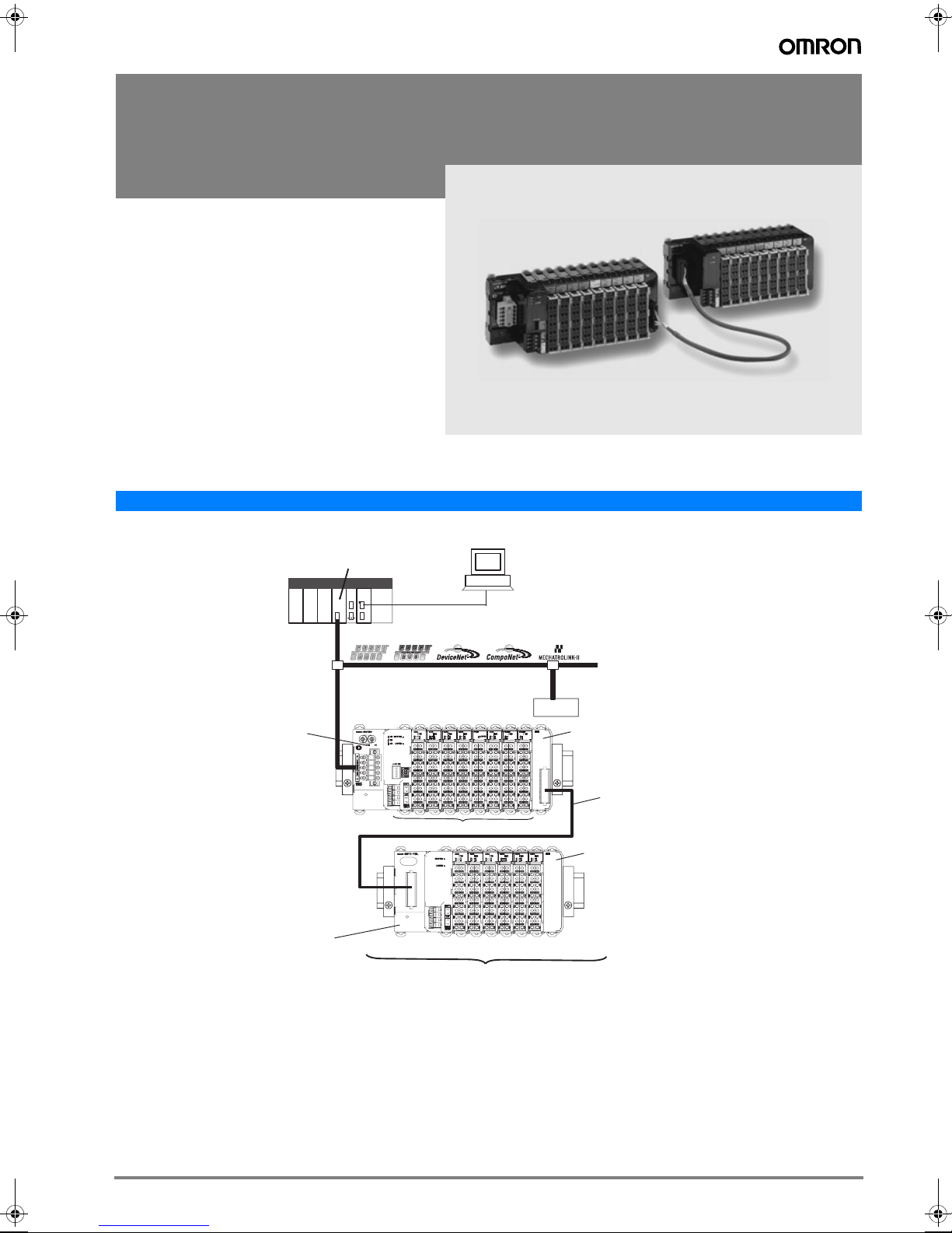
System Configuration
CS1/CJ1 PLC series or
Trajexia Motion Controller (ML-II only)
PLC
Communication Unit
GRT1-TBL Left Turnback Unit
Up to 64 I/O Units can be connected to a Communication Unit.
I/O Units
CX-One for setup,
monitoring and operation
of all OMRON Devices
Slave
GRT1-TBR Right Turnback Unit
GCN2-100 Turnback Cable (1 m)
Max. 2 per station.
GRT1-END End Unit
1SmartSlice
Page 2
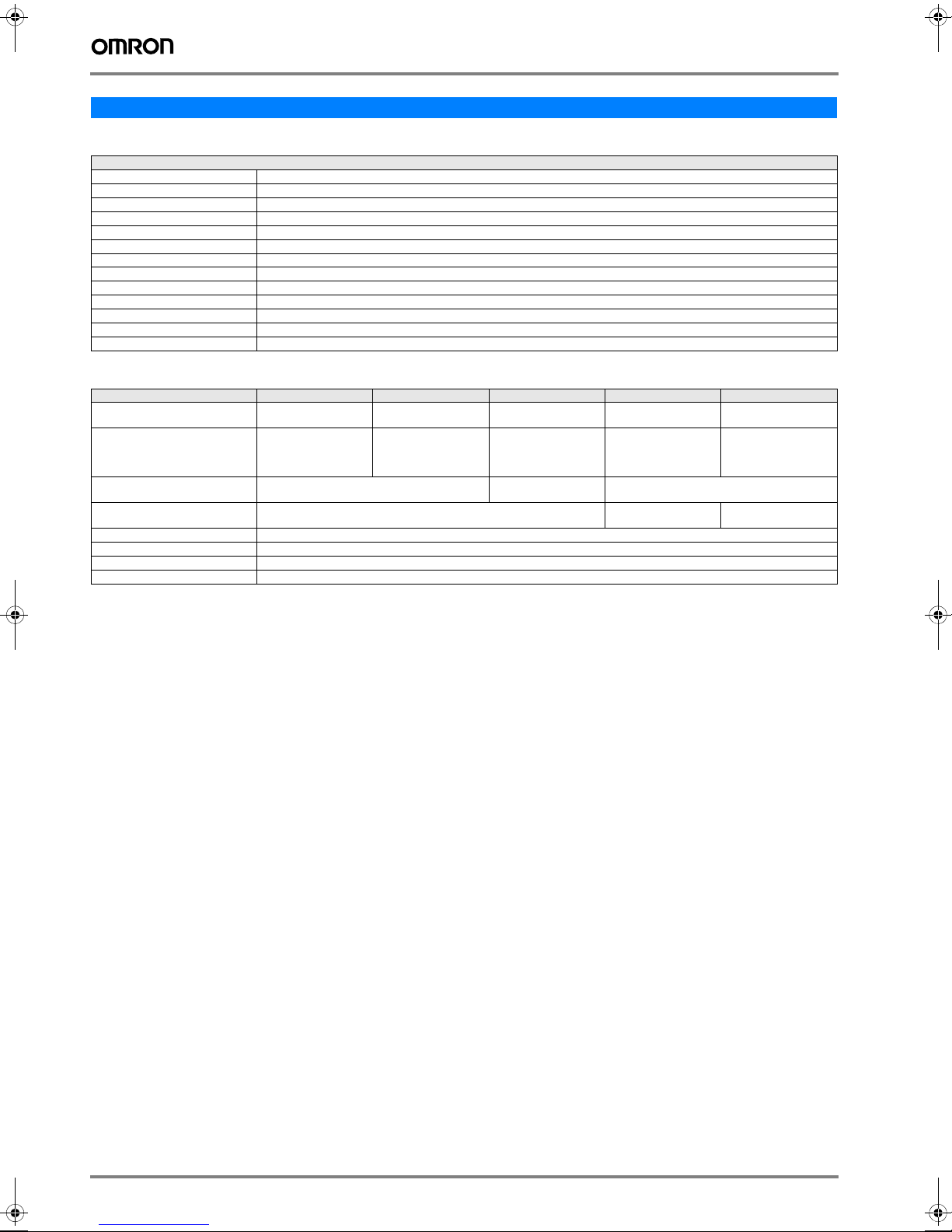
Specifications
General Specifications
Common SmartSlice Specifications
Unit power supply voltage 24 VDC (20.4 to 26.4 VDC)
I/O power supply voltage 24 VDC (20.4 to 26.4 VDC)
I/O connection Screwless push-in technology
Noise immunity Conforms to IEC61000-4-4, 2.0 kV (power supply line)
Vibration resistance 10 to 60 Hz: 0.7 mm double amplitude 60 to 150 Hz: 50 m/s
Shock resistance 150 m/s2, 3 times in each direction
Dielectric strength 500 VAC (between isolated circuits)
Insulation resistance 20 MΩ min. (between isolated circuits)
Ambient operating temperature -10 to 55°C (with no icing or condensation)
Ambient operating humidity 25% to 85%
Operating environment No corrosive gases
Ambient storage temperature -25 to 65°C (with no icing or condensation)
Mounting 35 mm DIN rail
Communication Units
Model name GRT1-PNT GRT1-PRT GRT1-DRT GRT1-CRT GRT1-ML2
Network Specification PROFINET-IO PROFIBUS-DPV1 DeviceNet CompoNet MECHATROLINK-II for
Network connector 2 x RJ45, built-in switch
Network interface power supply Internal External,
Number of I/O points 1,024 inputs and outputs max. (128 bytes each) 32 bytes input + 32 bytes
Number of connectable Units 64 SmartSlice I/O Units max.
I/O power supply 24 VDC, 4 A max.
Status flags 1 word for Communications Unit status flags
Parameter backup and restore up to 2 KB of data per I/O Unit.
with support for MRP redundancy.
9-pin D-Sub Open-style DeviceNet
2
connector,
dual screwless push-in
dual connections.
11 to 25 VDC, 22 mA
4-pin CompoNet 2 x ML-II
Internal
output max.
Trajexia
1,024 inputs and outputs
max. (128 bytes each)
2 Control System
Page 3
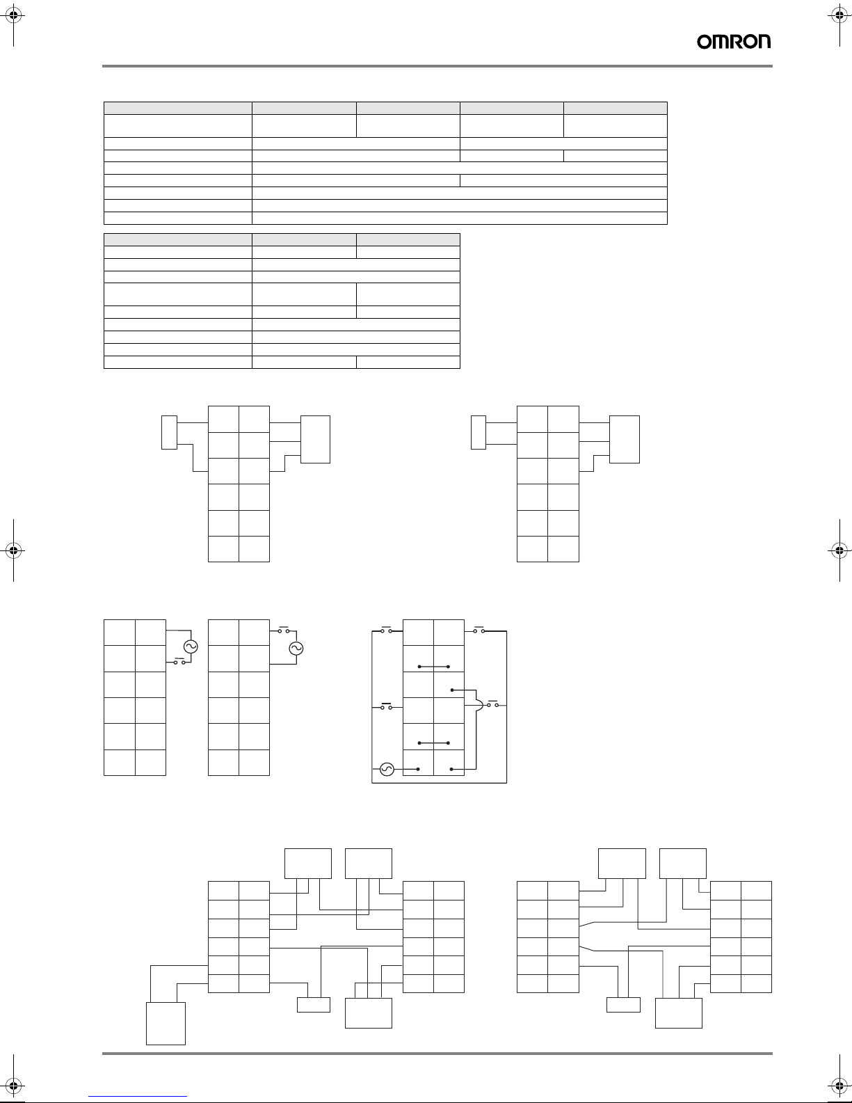
Digital Input Units
Model name GRT1-ID4 GRT1-ID4-1 GRT1-ID8 GRT1-ID8-1
Signal type DC input (for sinking out-
puts, NPN type)
Number of input points 4 inputs 8 inputs
Power terminals 4 x V (24 V) + 4 x G (0 V) 4 x G (0 V) 4 x V (24 V)
ON voltage 15 VDC min.
ON current 6 mA max./point (at 24 VDC) 4 mA max./point (at 24 VDC)
OFF voltage 5 VDC max.
OFF current 1 mA max.
ON delay / OFF delay 1.5 ms max.
Model name GRT1-IA4-1 GRT1-IA4-2
Signal type AC input, 110 V AC input, 230 V
Number of input points 4 inputs
Power terminals None
Input voltage 100 to 120 VAC
-15% to +10%, 50/60 Hz
ON voltage 70 VAC min. 120 VAC min.
ON current 4 mA min.
OFF voltage 20 VAC max.
OFF current 2 mA max.
ON delay / OFF delay 10 ms max./55 ms max. 10 ms max./40 ms max.
GRT1-ID4 (NPN)
0
+
–
2-wire sensor
(such as a limit switch)
1
V
V
G
G
2
3
Signal
24 V
0 V
3-wire sensor
with NPN output
(photoelectric or
proximity sensor)
DC input (for sourcing
outputs, PNP type)
200 to 240 VAC
-15% to +10%, 50/60 Hz
GRT1-ID4 -1 (PNP)
2-wire sensor
(such as a limit switch)
DC input (for sinking outputs, NPN type)
–
+
0
V
G
2
DC input (for sourcing
outputs, PNP type)
1
V
G
3
Signal
24 V
0 V
3-wire sensor with NPN output
(photoelectric or proximity sensor)
V
V
G
G
V
V
G
G
GRT1-IA4-1/GRT1-IA4-2
0A 1A
0B 1B
0B 1B
2A 3A
2B 3B
2B 3B
Note: No common signal for inputs.
GRT1-ID8 (NPN) GRT1-ID8-1 (PNP)
+
External
24-V I/O
power
supply
−
0A 1A
0B 1B
0B 1B
2A 3A
2B 3B
2B 3B
GRT1-PD8
VV
VV
GG
VV
VV
GG
Note: Common signal for four inputs.
3-wire sensor 3-wire sensor
0 V
24 V
Signal
0 V
24 V
+
–
2-wire switch
0 V
24 V
3-wire sensor 3-wire sensor
Signal
Signal
GRT1-ID8
0A 1A
0B 1B
0B 1B
2A 3A
2B 3B
2B 3B
01
23
GG
45
67
GG
GRT1-PC8-1
GG
VV
GG
GG
VV
GG
3-wire sensor 3-wire sensor
0 V
24 V
Signal
0 V
+
–
2-wire switch
0 V
24 V
24 V
Signal
Signal
GRT1-ID8-1
01
VV
23
45
VV
67
SmartSlice 3
Page 4

Digital Output Units
Model name GRT1-OD4 GRT1-OD4-1 GRT1-OD4G-1 GRT1-OD4G-3
Signal type Transistor output
Number of output points 4 outputs
Power terminals 4 x V (24 V) 4 x G (0 V) 4 x V (24 V) + 4 x G (0 V)
Rated voltage 24 VDC (20.4 to 26.4 VDC) 24 V I/O power supply
Rated output current 500 mA max./point from 4 x 2.0 A at 30 °C
Residual voltage 1.2 VDC max. (at 500 mA) 1.2 VDC max. (at 2 A)
Leakage cuurent 0.1 mA max.
ON delay / Off delay 0.5 / 1.5 ms max.
(NPN type, sinking)
Transistor output
(PNP type, sourcing)
Transistor output
(PNP type, sourcing), with short-circuit protection
via the front terminal of
the unit.
to 4 x 1.0 A at 55 °C
Model name GRT1-OD8 GRT1-OD8-1 GRT1-OD8G-1 GRT1-ROS2
Signal type Transistor output
Number of output points 8 outputs 2 outputs (with 2 termi-
Power terminals 4 x V (24 V) 4 x G (0 V) n.a.
Rated voltage 24 VDC (20.4 to 26.4 VDC) 250 VAC / 24 VDC
Rated output current 500 mA max./point 2 A (min. 1 mA @ 5 VDC)
Residual voltage 1.2 VDC max. (at 500 mA) Leakage cuurent 0.1 mA max. ON delay / Off delay 0.5 / 1.5 ms max. 15 ms max.
Mechanical life expectancy - 20,000,000 times min.
Electrical life expectancy - 100,000 times min.
(NPN type, sinking)
GRT1-OD4
0
NC
NC
1
V
V
NC
2
3
V
V
NC
Solenoid,
valve, etc.
Transistor output
(PNP type, sourcing)
GRT1-OD4-1
0
1
NC
G
NC
NC
G
2
3
NC
G
G
Transistor output
(PNP type, sourcing),
with short-circuit protection
Solenoid,
valve, etc.
Relay output
(normally open)
nals per connection)
GRT1-OD4G-1 (PNP)
0
1
V
V
G
G
2
3
V
V
G
G
Solenoid,
valve, etc.
3-wire
actuator
3-wire
GRT1-PC8-1 GRT1-OD8
G
G
V
V
G
G
G
G
V
V
G
G
actuator
Solenoid,
valve, etc.
3-wire
actuator
3-wire
actuator
4 Control System
GRT1-OD8 (NPN)
0
1
V
V
2
3
4
5
V
V
6
7
GRT1-OD4G-3 (PNP)
G
G
0
0
24 VDC
G
G
+
V
V
2
2
G
G
G
G
1
1
G
G
V
V
3
3
G
G
Solenoid,
valve, etc.
3-wire
actucator
Page 5

3-wire
actuator
V
V
V
V
G
G
V
V
V
V
G
G
3-wire
actuator
GRT1-OD8(G)-1 (PNP)
GRT1-OD8-1GRT1-PC8
1
0
3
2
G
G
5
4
7
6
G
G
GRT1-ROS2
0
0
C0
C0
NC
NC
1
1
C1
C1
NC
NC
AC power supply
(or DC power supply)
Load
AC power supply
(or DC power supply)
Load
Solenoid,
valve, etc.
3-wire
actuator
Pulse I/O Units
Model name GRT1-CT1 GRT1-CT1-1 GRT1-CP1-L
Counter input A/B incremental
Counter signal type 24 VDC, NPN type 24 VDC, PNP type 24 VDC, PNP type, or
Max. frequency 60 kHz 100 kHz
Counter range 32 bit double signed integer
Comparison values 1 range (2 comparison values) 2 independent ranges
Control Input IN0, DC input (NPN type) IN0, DC input (PNP type)
Control Input functions Capture, Preset, Reset Capture, Preset, Reset,
Control Outputs OUT0, Transistor Output
Control Output functions Range comparison, manual override
Additional functions On-the-fly reconfiguration, Frequency measurement
encoder,
or pulse/direction,
or pulse up/down
(NPN, sinking)
A/B incremental
encoder,
or pulse/direction,
or pulse up/down
OUT0, Transistor Output
(PNP, sourcing)
A/B/Z incremental
encoder,
or pulse/direction/reset
RS422 Line driver levels
Z enable
OUT0, OUT1, Transistor
Output (PNP, sourcing)
GRT1-CT1(-1) GRT1-CP1-L
GRT1-CT1 (NPN)
A
OUT
B
V
Z/IN
N.C.
GRT1-CT1-1 (PNP)
A
OUT
B
N.C.
Z/IN
G
24-V rotary encoder
(all DIP switch pins ON)
A
N.C.
B
N.C.
Z
N.C.
Line driver rotary encoder
(all DIP switch pins OFF)
A+
A–
B+
B–
Z+
Z–
N.C.
N.C.
V
V
G
G
N.C.
V
G
N.C.
V
G
SmartSlice 5
IN
OUT0
V
OUT1
G
G
IN
OUT0
V
OUT1
G
G
Page 6

Analog I/O Units
Model name GRT1-AD2 GRT1-DA2V GRT1-DA2C
Signal type Analog Input: 0-20mA,
4-20mA,
±10V, 0-10V, 0-5V, 1-5V
Analog Output:
±10V, 0-10V, 0-5V, 1-5V
Analog Output:
0-20mA, 4-20mA,
Number of points 2 inputs 2 outputs
Resolution 1/6000 full scale
Conversion time 2ms / 2points
Model name GRT1-TS2P GRT1-TS2PK GRT1-TS2T
Signal type Temperature input,
Pt100, (2-wire, 3-wire)
Temperature input,
Pt1000, (2-wire, 3-wire)
Thermocouple,
R, S, K, J, T, E, B, N, L,
U, W, or PL2
Number of points 2 inputs
Indication range -200 to +200 °C /
Accuracy ±0.3% of PV or ±0.8 °C* (whichever is larger)
Resolution 0.1 °C, 16-bit signed integer, or
-200 to +850 °C
±1 digit max.
* (or ±0.5 °C for -200 °C to +200 °C input range)
0.01 °C, 32-bit signed double integer
Depends on thremocou-
ple type
±2°C ±1 digit max.
Mounting restrictions
apply. See Operation
Manual W455
Conversion time 250 ms / 2 points
GRT1-AD2 GRT1-DA2V GRT1-DA2C
NC NC
NC NC
NC NC
IN0
Short for IN0
current input
0 + 1 +
0 - 1 -
AG AG
Sh0 Sh1
Sh0 Sh1
IN1
Short for IN1
current input
NC NC
NC NC
V0 + V1 +
OUT
0
0 - 1 -
OUT
1
NC NC
GRT1-TS2P/PK (2-wire) GRT1-TS2P/PK (3-wire) GRT1-TS2T
0A 1A
0B 1B
0B 1B
SHT
0A
SHT
0B
NC
SHT
1A
SHT
1B
NC
0A 1A
0B 1B
0B 1B
SHT
SHT
0A
1A
SHT0BSHT
1B
NC NC
Thermocouple input
Cold Junction Sensor
(do not remove)
NC NC
NC NC
I0 + I1 +
OUT
0
0 - 1 -
OUT
1
NC NC
NC
NC
1−
0−
1+
0+
NC
NC
NC
NC
6 Control System
Page 7

Power Feed and Distribution Units
GRT1-PD2 GRT1-PD2G GRT1-PD8
NC
24 VDC
NC
NC
V
G
NC
NC
NC
NC
V
G
NC
24 VDC
RESET
V(R)
NC
V
G
NC
NC
NC
NC
NC
V
V
G
V
G
24 VDC
V
V
G
GRT1-PD8-1 GRT1-PC8 GRT1-PC8-1
G
V
G
G
V
G
24 VDC
G
G
V
V
G
G
G
G
V
V
G
G
V
V
V
V
G
G
V
V
V
V
G
G
V
V
G
V
V
G
G
V
G
G
V
G
SmartSlice 7
Page 8

Dimensions
I/O-units Communication Units
End units
GRT1-END
GRT1-END-M
GRT1-TBR
GRT1-CRT
GRT1-DRT
GRT1-ML2
GRT1-PNT
GRT1-PRT
GRT1-TBL
8 Control System
Page 9

Ordering Information
Communication Units
Function Specification Model code
DeviceNet interface unit For up to 64 I/O units 84x58x70 GRT1-DRT
CompoNet interface unit For up to 64 I/O units (limited to 32 byte in + 32 byte out) 84x58x70 GRT1-CRT
PROFIBUS-DP interface unit For up to 64 I/O units 84x58x70 GRT1-PRT
PROFINET-IO interface unit For up to 64 I/O units 84x58x70 GRT1-PNT
MECHATROLINK-II interface unit For up to 64 I/O units (slave to Trajexia motion controller) 84x58x70 GRT1-ML2
End plate One unit required per bus interface 84x20x58 GRT1-END
End plate with memory function Supports toolless replacement of PROFINET-IO interface unit 84x20x58 GRT1-END-M
*1
Available 06-2008
I/O units
Function Specification Model code
4 NPN inputs 24 VDC, 6 mA, 3-wire connection 84x15x74 GRT1-ID4
4 PNP inputs 24 VDC, 6 mA, 3-wire connection 84x15x74 GRT1-ID4-1
8 NPN inputs 24 VDC, 4 mA, 1-wire connection + 4xG 84x15x74 GRT1-ID8
8 PNP inputs 24 VDC, 4 mA, 1-wire connection + 4xV 84x15x74 GRT1-ID8-1
4 AC inputs 110 VAC, 2-wire connection 84x15x74 GRT1-IA4-1
4 AC inputs 230 VAC, 2-wire connection 84x15x74 GRT1-IA4-2
4 NPN outputs 24 VDC, 500 mA, 2-wire connection 84x15x74 GRT1-OD4
4 PNP outputs 24 VDC, 500 mA, 2-wire connection 84x15x74 GRT1-OD4-1
4 PNP outputs with short-circuit protection 24 VDC, 500 mA, 3-wire connection 84x15x74 GRT1-OD4G-1
4 PNP outputs with short-circuit protection 24 VDC, 2 A, 2-wire connection 84x15x74 GRT1-OD4G-3
8 NPN outputs 24 VDC, 500 mA, 1-wire connection + 4xV 84x15x74 GRT1-OD8
8 PNP outputs 24 VDC, 500 mA, 1-wire connection + 4xG 84x15x74 GRT1-OD8-1
8 PNP outputs with short-circuit protection 24 VDC, 500 mA, 1-wire connection + 4xG 84x15x74 GRT1-OD8G-1
2 relay outputs 240 VAC, 2A, normally-open contacts 84x15x74 GRT1-ROS2
60 kHz Counter unit, NPN A+B encoder inputs + 1 Z/control input + 1 output (NPN-type) 84x15x74 GRT1-CT1
60 kHz Counter unit, PNP A+B encoder inputs + 1 Z/control input + 1 output (PNP-type) 84x15x74 GRT1-CT1-1
100 kHz Counter / Positioner unit A+B+Z encoder inputs (line driver or 24 V selectable) +
2 analog inputs, current/voltage ±10 V, 0-10 V, 0-5 V, 1-5 V, 0-20 mA, 4-20 mA 84x15x74 GRT1-AD2
2 analog outputs, voltage ±10 V, 0-10 V, 0-5 V, 1-5 V 84x15x74 GRT1-DA2V
2 analog outputs, current 0-20 mA, 4-20 mA 84x15x74 GRT1-DA2C
2 Pt100 inputs Pt100, 2-wire or 3-wire connection 84x15x74 GRT1-TS2P
2 Pt1000 inputs Pt1000, 2-wire or 3-wire connection 84x15x74 GRT1-TS2PK
2 Thermocouple inputs Types B, E, J, K, N, R, S, T, U, W, PL2, with cold junction compen-
1 control input + 2 outputs (PNP-type)
sation
84x15x74 GRT1-CP1-L
84x15x74 GRT1-TS2T
*1
*1
Other units
Function Model code
I/O power feed unit, separates power supply between groups of I/O units 84x15x74 GRT1-PD2
I/O power feed unit with electronic overload protection, separates power supply between groups of I/O units 84x15x74 GRT1-PD2G
I/O power feed and distribution unit, separates power supply between groups of I/O units, 8xV + 4xG 84x15x74 GRT1-PD8
I/O power feed and distribution unit, separates power supply between groups of I/O units, 4xV + 8xG 84x15x74 GRT1-PD8-1
I/O power connection unit, 8xV + 4xG 84x15x74 GRT1-PC8
I/O power connection unit, 4xV + 8xG 84x15x74 GRT1-PC8-1
Turnback Unit, right-hand side 84x20x58 GRT1-TBR
Turnback Unit, left-hand side 84x58x70 GRT1-TBL
Turnback cable, one meter 1 m GCN2-100
Accessories
Function Model code
Replacement front connectors, pack of 5 pcs. GRT1-BT1-5
PROFIBUS-DP connector, 9-pin D-sub PROFIBUS Connector
PROFIBUS-DP connector, 9-pin D-sub, with bus termination PROFIBUS Term. Conn.
CompoNet screw terminal connector (order per 10 pcs) DCN4-TB4
CompoNet branch line connector (order per 10 pcs) DCN4-BR4
CompoNet Y-connector (order per 10 pcs) DCN4-MD4
839550
846086
SmartSlice 9
Page 10

Master Units
Function Model code
PROFINET-IO Controller for CJ1-series PLCs CJ1W-PNT21
PROFIBUS-DP Master Unit for CS1-series PLCs CS1W-PRM21
PROFIBUS-DP Master Unit for CJ1-series PLCs CJ1W-PRM21
DeviceNet Master Unit for CS1-series PLCs CS1W-DRM21-V1
DeviceNet Master Unit for CJ1-series PLCs CJ1W-DRM21
CompoNet Master Unit for CS1-series PLCs CS1W-CRM21
CompoNet Master Unit for CJ1-series PLCs CJ1W-CRM21
MECHATROLINK-II Master Unit for Trajexia (4 stations max.) TJ1-ML04
MECHATROLINK-II Master Unit for Trajexia (16 stations max.) TJ1-ML16
HMI with PLC and DeviceNet Master NSJxx-T@@@@-G5D
HMI with PLC and PROFIBUS-DP Master NSJxx-T@@@@-G5P
*1
Available 06-2008
*1
Software
Function Model code
CX-One, Omron's integrated software for programming and configuration of all control system components,
including PLCs, remote I/O, HMI, servo drives, inverters, temperature controllers and advanced sensors.
CX-ONE-AL@@ C-E
@@ = number of licenses
(01, 03, 10)
In the interest of product improvement, specifications are subject to change without notice.Cat. No. P15E-EN-03A
OMRON EUROPE B.V.
Wegalaan 67-69,
NL-2132 JD, Hoofddorp,
The Netherlands
Phone: +31 23 568 13 00
Fax: +31 23 568 13 88
www.industrial.omron.eu
10 Control System
 Loading...