

Page 1

DeviceNet Communications Unit
Cat. No. W454-E1-03
SmartSlice
GRT1-DRT
OPERATION MANUAL
Page 2

SmartSlice
GRT1-DRT
DeviceNet Communications Unit
Operation Manual
Revised April 2008
Page 3

iv
Page 4

v
Notice:
OMRON products are manufactured for use according to proper procedures by a qualified operator
and only for the purposes described in this manual.
The following conventions are used to indicate and classify precautions in this manual. Always heed
the information provided with them. Failure to heed precautions can result in injury to people or damage to property.
!DANGER Indicates an imminently hazardous situation which, if not avoided, will result in death or
serious injury. Additionally, there may be severe property damage.
!WARNING Indicates a potentially hazardous situation which, if not avoided, could result in death or
serious injury. Additionally, there may be severe property damage.
!Caution Indicates a potentially hazardous situation which, if not avoided, may result in minor or
moderate injury, or property damage.
OMRON Product References
All OMRON products are capitalized in this manual. The word “Unit” is also capitalized when it refers to
an OMRON product, regardless of whether or not it appears in the proper name of the product.
The abbreviation “Ch,” which appears in some displays and on some OMRON products, often means
“word” and is abbreviated “Wd” in documentation in this sense.
The abbreviation “PLC” means Programmable Controller. “PC” is used, however, in some Programming Device displays to mean Programmable Controller.
Visual Aids
The following headings appear in the left column of the manual to help you locate different types of
information.
Note Indicates information of particular interest for efficient and convenient opera-
tion of the product.
1,2,3... 1. Indicates lists of one sort or another, such as procedures, checklists, etc.
OMRON, 2005
All rights reserved. No part of this publication may be reproduced, stored in a retrieval system, or transmitted, in any form, o
r
by any means, mechanical, electronic, photocopying, recording, or otherwise, without the prior written permission o
f
OMRON.
No patent liability is assumed with respect to the use of the information contained herein. Moreover, because OMRON is constantly striving to improve its high-quality products, the information contained in this manual is subject to change without
notice. Every precaution has been taken in the preparation of this manual. Nevertheless, OMRON assumes no responsibility
for errors or omissions. Neither is any liability assumed for damages resulting from the use of the information contained in
this publication.
Page 5

vi
Page 6

vii
TABLE OF CONTENTS
PRECAUTIONS . . . . . . . . . . . . . . . . . . . . . . . . . . . . . . . . . . . xv
1 Intended Audience. . . . . . . . . . . . . . . . . . . . . . . . . . . . . . . . . . . . . . . . . . . . . . . . . . . . . . . . . xvi
2 General Precautions. . . . . . . . . . . . . . . . . . . . . . . . . . . . . . . . . . . . . . . . . . . . . . . . . . . . . . . . xvi
3 Safety Precautions . . . . . . . . . . . . . . . . . . . . . . . . . . . . . . . . . . . . . . . . . . . . . . . . . . . . . . . . . xvi
4 Operating Environment Precautions . . . . . . . . . . . . . . . . . . . . . . . . . . . . . . . . . . . . . . . . . . . xvii
5 Application Precautions. . . . . . . . . . . . . . . . . . . . . . . . . . . . . . . . . . . . . . . . . . . . . . . . . . . . .xviii
6 EC Directives . . . . . . . . . . . . . . . . . . . . . . . . . . . . . . . . . . . . . . . . . . . . . . . . . . . . . . . . . . . . . xix
SECTION 1
Overview . . . . . . . . . . . . . . . . . . . . . . . . . . . . . . . . . . . . . . . . . 1
1-1 Overview of Slice I/O Terminals. . . . . . . . . . . . . . . . . . . . . . . . . . . . . . . . . . . . . . . . . . . . . . 2
1-2 Features and System Configuration. . . . . . . . . . . . . . . . . . . . . . . . . . . . . . . . . . . . . . . . . . . . 2
1-3 Specifications. . . . . . . . . . . . . . . . . . . . . . . . . . . . . . . . . . . . . . . . . . . . . . . . . . . . . . . . . . . . . 4
1-4 List of Available Units. . . . . . . . . . . . . . . . . . . . . . . . . . . . . . . . . . . . . . . . . . . . . . . . . . . . . . 6
1-5 Basic Operating Procedure . . . . . . . . . . . . . . . . . . . . . . . . . . . . . . . . . . . . . . . . . . . . . . . . . .7
SECTION 2
Component Names and Functions. . . . . . . . . . . . . . . . . . . . . 9
2-1 Nomenclature and Dimensions . . . . . . . . . . . . . . . . . . . . . . . . . . . . . . . . . . . . . . . . . . . . . . . 10
2-2 Node Address Settings and I/O Allocation . . . . . . . . . . . . . . . . . . . . . . . . . . . . . . . . . . . . . . 14
2-3 Unit Functions . . . . . . . . . . . . . . . . . . . . . . . . . . . . . . . . . . . . . . . . . . . . . . . . . . . . . . . . . . . . 23
SECTION 3
Installation and Wiring . . . . . . . . . . . . . . . . . . . . . . . . . . . . . 39
3-1 Installation . . . . . . . . . . . . . . . . . . . . . . . . . . . . . . . . . . . . . . . . . . . . . . . . . . . . . . . . . . . . . . . 40
3-2 Power Supply Wiring. . . . . . . . . . . . . . . . . . . . . . . . . . . . . . . . . . . . . . . . . . . . . . . . . . . . . . . 44
3-3 Wiring DeviceNet Communications Cables . . . . . . . . . . . . . . . . . . . . . . . . . . . . . . . . . . . . . 47
3-4 Connecting the Turnback Cable . . . . . . . . . . . . . . . . . . . . . . . . . . . . . . . . . . . . . . . . . . . . . . 50
SECTION 4
Setup and Operating Procedures . . . . . . . . . . . . . . . . . . . . . 51
4-1 Basic Operating Procedure and Example Configuration. . . . . . . . . . . . . . . . . . . . . . . . . . . . 52
4-2 Preparation for Operation . . . . . . . . . . . . . . . . . . . . . . . . . . . . . . . . . . . . . . . . . . . . . . . . . . . 53
4-3 Setting and Wiring Hardware . . . . . . . . . . . . . . . . . . . . . . . . . . . . . . . . . . . . . . . . . . . . . . . . 55
4-4 Starting Communications . . . . . . . . . . . . . . . . . . . . . . . . . . . . . . . . . . . . . . . . . . . . . . . . . . .57
4-5 Checking Operation. . . . . . . . . . . . . . . . . . . . . . . . . . . . . . . . . . . . . . . . . . . . . . . . . . . . . . . . 60
SECTION 5
Communications Characteristics . . . . . . . . . . . . . . . . . . . . . 61
5-1 Remote I/O Communications Characteristics . . . . . . . . . . . . . . . . . . . . . . . . . . . . . . . . . . . . 62
5-2 Message Communications Characteristics . . . . . . . . . . . . . . . . . . . . . . . . . . . . . . . . . . . . . . 66
Page 7

viii
TABLE OF CONTENTS
SECTION 6
Troubleshooting . . . . . . . . . . . . . . . . . . . . . . . . . . . . . . . . . . . 67
6-1 Troubleshooting Overview . . . . . . . . . . . . . . . . . . . . . . . . . . . . . . . . . . . . . . . . . . . . . . . . . . 68
6-2 LED Indicators and Error Processing . . . . . . . . . . . . . . . . . . . . . . . . . . . . . . . . . . . . . . . . . . 68
6-3 Reading the Error History with the DeviceNet Configurator . . . . . . . . . . . . . . . . . . . . . . . . 71
6-4 Other Errors . . . . . . . . . . . . . . . . . . . . . . . . . . . . . . . . . . . . . . . . . . . . . . . . . . . . . . . . . . . . . . 74
Appendices
A DeviceNet Explicit Messages . . . . . . . . . . . . . . . . . . . . . . . . . . . . . . . . . . . . . . . . . . . . . . . . 77
B Using Another Company's Master Unit . . . . . . . . . . . . . . . . . . . . . . . . . . . . . . . . . . . . . . . . 83
C Standard Models . . . . . . . . . . . . . . . . . . . . . . . . . . . . . . . . . . . . . . . . . . . . . . . . . . . . . . . . . . 91
D Power Consumption Tables . . . . . . . . . . . . . . . . . . . . . . . . . . . . . . . . . . . . . . . . . . . . . . . . . 95
E I/O Current Consumption . . . . . . . . . . . . . . . . . . . . . . . . . . . . . . . . . . . . . . . . . . . . . . . . . . . 97
Glossary . . . . . . . . . . . . . . . . . . . . . . . . . . . . . . . . . . . . . . . . . . 99
Index. . . . . . . . . . . . . . . . . . . . . . . . . . . . . . . . . . . . . . . . . . . . . 101
Revision History . . . . . . . . . . . . . . . . . . . . . . . . . . . . . . . . . . . 103
Page 8

ix
About this Manual:
This manual describes the installation and operation of the DeviceNet Communications Unit for Slice I/
O Terminals and includes the sections described below. The DeviceNet Communications Unit for Slice
I/O Terminals is an interface Unit that connects Slice I/O Units with a DeviceNet Master.
Please read this manual carefully and be sure you understand the information provided before
attempting to install or operate the DeviceNet Communications Units. Be sure to read the precau-
tions provided in the following section.
The following manuals also cover information related to DeviceNet applications. Use the DeviceNet
Operation Manual together with other required manuals.
Precautions provides general precautions for planning, installing, and operating the DeviceNet Communications Unit and related devices.
Section 1 provides an overview of the DeviceNet Communications Unit with information such as the
features and system configuration.
Section 2 describes the DeviceNet Communications Unit’s components, describes the Unit’s functions
in detail, and explains how to allocate I/O.
Section 3 explains how to install and wire the DeviceNet Communications Unit and Slice I/O Terminals.
Section 4 describes the procedures required to begin actual communications between the DeviceNet
Communications Unit and Slice I/O Terminals.
Section 5 provides information on communications using the remote I/O communications function and
message communications function, such as response times and transmission delays.
Section 6 explains how to monitor and correct errors that occur in a DeviceNet Communications Unit
or Slice I/O Unit, interpret the Unit’s LED indicators, and read the error history from the DeviceNet Configurator.
Appendix explains how to handle EDS setting files required for multivendor environments and how to
list the device profile of the DeviceNet Communications Unit and information on related products.
Manual Contents Cat. No.
DeviceNet Communications Unit
for Slice I/O Terminals
Operation Manual
(this manual)
Describes the specifications, functions, operating procedures, and
applications of the DeviceNet Communications Unit, which allows
Slice I/O Units to be set, controlled, and monitored through
DeviceNet.
W454
GRT1 Series
Slice I/O Units
Operation Manual
Describes the models, specifications, functions, operating procedures, and applications of GRT1-series Slice I/O Units.
W455
DeviceNet
Operation Manual
Describes the configuration and construction of a DeviceNet network,
including installation procedures and specifications for cables, connectors, and other connection devices, as well as information on
functions, operating procedures, and applications.
Read this manual carefully and be sure you understand the information provided before attempting to use DeviceNet.
W267
CS/CJ Series
DeviceNet Units
Operation Manual
Describes the specifications, functions, operating procedures, and
applications of CS-series and CJ-series DeviceNet Units. (A CS/CJseries DeviceNet Unit can operate as both a DeviceNet master and
DeviceNet slave at the same time.)
W380
DeviceNet Configurator Ver. 2.@
Operation Manual
Describes the operating procedures of the DeviceNet Configurator.
The DeviceNet Configurator can be used to configure, set, and maintain a DeviceNet system through an easy-to-use graphical interface.
Refer to this manual when necessary.
W382
Page 9

x
!WARNING Failure to read and understand the information provided in this manual may result in per-
sonal injury or death, damage to the product, or product failure. Please read each section
in its entirety and be sure you understand the information provided in the section and
related sections before attempting any of the procedures or operations given.
Page 10

xi
Read and Understand this Manual
Please read and understand this manual before using the product. Please consult your OMRON
representative if you have any questions or comments.
Warranty and Limitations of Liability
WARRANTY
OMRON's exclusive warranty is that the products are free from defects in materials and workmanship for a
period of one year (or other period if specified) from date of sale by OMRON.
OMRON MAKES NO WARRANTY OR REPRESENTATION, EXPRESS OR IMPLIED, REGARDING NONINFRINGEMENT, MERCHANTABILITY, OR FITNESS FOR PARTICULAR PURPOSE OF THE
PRODUCTS. ANY BUYER OR USER ACKNOWLEDGES THAT THE BUYER OR USER ALONE HAS
DETERMINED THAT THE PRODUCTS WILL SUITABLY MEET THE REQUIREMENTS OF THEIR
INTENDED USE. OMRON DISCLAIMS ALL OTHER WARRANTIES, EXPRESS OR IMPLIED.
LIMITATIONS OF LIABILITY
OMRON SHALL NOT BE RESPONSIBLE FOR SPECIAL, INDIRECT, OR CONSEQUENTIAL DAMAGES,
LOSS OF PROFITS OR COMMERCIAL LOSS IN ANY WAY CONNECTED WITH THE PRODUCTS,
WHETHER SUCH CLAIM IS BASED ON CONTRACT, WARRANTY, NEGLIGENCE, OR STRICT
LIABILITY.
In no event shall the responsibility of OMRON for any act exceed the individual price of the product on which
liability is asserted.
IN NO EVENT SHALL OMRON BE RESPONSIBLE FOR WARRANTY, REPAIR, OR OTHER CLAIMS
REGARDING THE PRODUCTS UNLESS OMRON'S ANALYSIS CONFIRMS THAT THE PRODUCTS
WERE PROPERLY HANDLED, STORED, INSTALLED, AND MAINTAINED AND NOT SUBJECT TO
CONTAMINATION, ABUSE, MISUSE, OR INAPPROPRIATE MODIFICATION OR REPAIR.
Page 11

xii
Application Considerations
SUITABILITY FOR USE
OMRON shall not be responsible for conformity with any standards, codes, or regulations that apply to the
combination of products in the customer's application or use of the products.
At the customer's request, OMRON will provide applicable third party certification documents identifying
ratings and limitations of use that apply to the products. This information by itself is not sufficient for a
complete determination of the suitability of the products in combination with the end product, machine,
system, or other application or use.
The following are some examples of applications for which particular attention must be given. This is not
intended to be an exhaustive list of all possible uses of the products, nor is it intended to imply that the uses
listed may be suitable for the products:
• Outdoor use, uses involving potential chemical contamination or electrical interference, or conditions or
uses not described in this manual.
• Nuclear energy control systems, combustion systems, railroad systems, aviation systems, medical
equipment, amusement machines, vehicles, safety equipment, and installations subject to separate
industry or government regulations.
• Systems, machines, and equipment that could present a risk to life or property.
Please know and observe all prohibitions of use applicable to the products.
NEVER USE THE PRODUCTS FOR AN APPLICATION INVOLVING SERIOUS RISK TO LIFE OR
PROPERTY WITHOUT ENSURING THAT THE SYSTEM AS A WHOLE HAS BEEN DESIGNED TO
ADDRESS THE RISKS, AND THAT THE OMRON PRODUCTS ARE PROPERLY RATED AND
INSTALLED FOR THE INTENDED USE WITHIN THE OVERALL EQUIPMENT OR SYSTEM.
PROGRAMMABLE PRODUCTS
OMRON shall not be responsible for the user's programming of a programmable product, or any
consequence thereof.
Page 12

xiii
Disclaimers
CHANGE IN SPECIFICATIONS
Product specifications and accessories may be changed at any time based on improvements and other
reasons.
It is our practice to change model numbers when published ratings or features are changed, or when
significant construction changes are made. However, some specifications of the products may be changed
without any notice. When in doubt, special model numbers may be assigned to fix or establish key
specifications for your application on your request. Please consult with your OMRON representative at any
time to confirm actual specifications of purchased products.
DIMENSIONS AND WEIGHTS
Dimensions and weights are nominal and are not to be used for manufacturing purposes, even when
tolerances are shown.
PERFORMANCE DATA
Performance data given in this manual is provided as a guide for the user in determining suitability and does
not constitute a warranty. It may represent the result of OMRON's test conditions, and the users must
correlate it to actual application requirements. Actual performance is subject to the OMRON Warranty and
Limitations of Liability.
ERRORS AND OMISSIONS
The information in this manual has been carefully checked and is believed to be accurate; however, no
responsibility is assumed for clerical, typographical, or proofreading errors, or omissions.
Page 13

xiv
Page 14

xv
PRECAUTIONS
This section provides general precautions for installing and using the DeviceNet Communications Unit and related devices.
The information contained in this section is important for the safe and reliable application of the DeviceNet
Communications Unit. You must read this section and understand the information contained before attempting to
set up or operate a DeviceNet network using a DeviceNet Communications Unit.
1 Intended Audience . . . . . . . . . . . . . . . . . . . . . . . . . . . . . . . . . . . . . . . . . . . . . xvi
2 General Precautions . . . . . . . . . . . . . . . . . . . . . . . . . . . . . . . . . . . . . . . . . . . . xvi
3 Safety Precautions. . . . . . . . . . . . . . . . . . . . . . . . . . . . . . . . . . . . . . . . . . . . . . xvi
4 Operating Environment Precautions . . . . . . . . . . . . . . . . . . . . . . . . . . . . . . . . xvii
5 Application Precautions . . . . . . . . . . . . . . . . . . . . . . . . . . . . . . . . . . . . . . . . . xviii
6 EC Directives . . . . . . . . . . . . . . . . . . . . . . . . . . . . . . . . . . . . . . . . . . . . . . . . . xix
Page 15

xvi
Intended Audience 1
1 Intended Audience
This manual is intended for the following personnel, who must also have
knowledge of electrical systems (an electrical engineer or the equivalent).
• Personnel in charge of purchasing FA systems.
• Personnel in charge of designing FA systems.
• Personnel in charge of installing and connecting FA systems.
• Personnel in charge of managing FA systems and facilities.
2 General Precautions
The user must operate the product according to the specifications described
in the operation manuals.
Before using the product under conditions which are not described in the
manual or applying the product to nuclear control systems, railroad systems,
aviation systems, vehicles, combustion systems, medical equipment, amusement machines, safety equipment, and other systems, machines, and equipment that may have a serious influence on lives and property if used
improperly, consult your OMRON representative.
Make sure that the ratings and performance characteristics of the product are
sufficient for the systems, machines, and equipment, and be sure to provide
the systems, machines, and equipment with redundant safety mechanisms.
This manual provides information for installing and operating OMRON
DeviceNet products. Be sure to read this manual before operation and keep
this manual close at hand for reference during operation.
!WARNING It is extremely important that a PLC and all PLC Units be used for the speci-
fied purpose and under the specified conditions, especially in applications that
can directly or indirectly affect human life. You must consult with your OMRON
representative before applying a PLC system to the above mentioned applications.
3 Safety Precautions
!WARNING Never attempt to disassemble any Units or touch the terminal block while
power is being supplied. Doing so may result in serious electrical shock or
electrocution.
!WARNING Provide safety measures in external circuits (i.e., not in the Programmable
Controller), including the following items, to ensure safety in the system if an
abnormality occurs due to malfunction of the PLC or another external factor
affecting the PLC operation. Not doing so may result in serious accidents.
• Emergency stop circuits, interlock circuits, limit circuits, and similar safety
measures must be provided in external control circuits.
• The PLC will stop operation when its self-diagnosis function detects any
error or when a severe failure alarm (FALS) instruction is executed. As a
countermeasure for such errors, external safety measures must be provided to ensure safety in the system.
Page 16

xvii
Operating Environment Precautions 4
• The PLC outputs may remain ON or OFF due to deposits on or burning of
the output relays, or destruction of the output transistors. As a countermeasure for such problems, external safety measures must be provided
to ensure safety in the system.
• When the 24-V DC output (service power supply to the PLC) is overloaded or short-circuited, the voltage may drop and result in the outputs
being turned OFF. As a countermeasure for such problems, external
safety measures must be provided to ensure safety in the system.
• Slice I/O Terminals will continue operating even if one or more I/O Units is
removed from or falls out of the Slice I/O Terminal, i.e., the other I/O Units
will continue control operations, including outputs. As a countermeasure
for such a possibility, external safety measures must be provided to
ensure safety in the system.
!WARNING The CPU Unit refreshes I/O even when the program is stopped (i.e., even in
PROGRAM mode). Confirm safety thoroughly in advance before changing the
status of any part of memory allocated to Output Units, Special I/O Units, or
CPU Bus Units. Any changes to the data allocated to any Unit may result in
unexpected operation of the loads connected to the Unit. Any of the following
operations may result in changes to memory status.
• Transferring I/O memory data to the CPU Unit from a Programming
Device
• Changing present values in memory from a Programming Device
• Force-setting/-resetting bits from a Programming Device
• Transferring I/O memory files from a Memory Card or EM file memory to
the CPU Unit
• Transferring I/O memory from a host computer or from another PLC on a
network
4 Operating Environment Precautions
Install the system properly according to the directions in this manual.
Do not operate the control system in the following places.
• Locations subject to direct sunlight.
• Locations subject to temperatures or humidity outside the range specified
in the specifications.
• Locations subject to condensation as the result of severe changes in temperature.
• Locations subject to corrosive or flammable gases.
• Locations subject to dust (especially iron dust) or salts.
• Locations subject to water, oil, or chemicals (General Units)
• Locations subject to acid or chemicals.
• Locations subject to shock or vibration.
Take appropriate and sufficient countermeasures when installing systems in
the following locations:
• Locations subject to static electricity or other forms of noise.
• Locations subject to strong electromagnetic fields.
• Locations subject to possible exposure to radioactivity.
• Locations close to power supplies.
Page 17

xviii
Application Precautions 5
!Caution The operating environment of the PLC System can have a large effect on the
longevity and reliability of the system. Improper operating environments can
lead to malfunction, failure, and other unforeseeable problems with the PLC
System. Be sure that the operating environment is within the specified conditions at installation and remains within the specified conditions during the life
of the system.
5 Application Precautions
Observe the following precautions when using the DeviceNet Communications Unit.
• Fail-safe measures must be taken by the customer to ensure safety in the
event of incorrect, missing, or abnormal signals caused by broken signal
lines, momentary power interruptions, or other causes.
• Provide external interlock circuits, limit circuits, and other safety circuits in
addition to any provided within the PLC to ensure safety.
• Use the power supplies specified in the operation manuals.
• If the system is installed at a site with poor power supply conditions, take
appropriate measures to ensure that the power supply remains within the
rated voltage and frequency specifications.
• Provide circuit breakers and other safety measures to provide protection
against shorts in external wiring.
• Always ground the system to 100
Ω or less when installing the system to
protect against electrical shock.
• Mount the PLC securely on DIN Track or with screws.
• Always turn OFF the power supply when mounting a DeviceNet Communications Unit.
• Always turn OFF the communications power supply and the power supplies to the PLC and Slaves before attempting any of the following.
• Mounting or removing a Unit such as an I/O Unit, CPU Unit, Memory
Cassette, or Master Unit.
• Mounting or removing Remote I/O Terminal circuit sections.
• Assembling any devices or racks.
• Setting rotary switches.
• Connecting or wiring cables.
• Connecting or disconnecting connectors.
• Do not attempt to disassemble, repair, or modify any Units.
• Be sure that all the terminal screws are tightened to the torque specified
in the relevant manuals. Loose screws may cause fire, malfunction, or
damage the Unit.
• Be sure that all the mounting screws and cable connector screws are
tightened to the torque specified in the relevant manuals.
• Be sure that all the communications connector screws are tightened
securely. (The communications connector screw torque is 0.5 to 0.6 N•m.)
• Do not remove the label from a Unit before wiring. Always remove the
label after completing wiring, however, to ensure proper heat dispersion.
• Use the correct wiring components when wiring.
• Use crimp terminals for wiring. Do not connect bare stranded wires
directly to terminals.
• Double-check all wiring before turning ON the power supply.
Page 18

xix
EC Directives 6
• When wiring or performing other tasks, do not allow metal objects such as
wire strands to enter the Unit.
• Always follow the electrical specifications for terminal polarity, communications path wiring, power supply wiring, and I/O jumpers. Incorrect wiring
can cause failures.
• Always wire the Unit as shown in the manual.
• Be sure to press terminals until they are fully seated.
• Mount Units only after checking terminal blocks completely.
• Be sure that the communications cable connectors and other items with
locking devices are properly locked into place.
• Do not drop the Unit or subject the Unit to excessive vibration or shock.
Doing so may cause malfunction or damage to the Unit.
• Use the special packing box when transporting the Unit. Ensure that the
product is handled carefully so that no excessive vibration or impact is
applied to the product during transportation.
• Check the user program for proper execution before actually running it
with the system.
• Do not bend or pull the cables excessively.
• When connecting communications cables, always turn OFF the PLC
power supply, all Slave power supplies, and all communications power
supplies.
• Observe the following precautions when wiring the communications
cables.
• Wire the communications cables separately from the power lines or
high-tension lines.
• Do not bend the communications cables excessively.
• Do not pull on the communications cables excessively.
• Do not place objects on top of the communications cables.
• Route communications cables inside ducts.
• Always enable the scan list before operation.
• Before clearing the scan list of a Unit that has user-allocated remote I/O,
always confirm that no errors occur after the I/O Area setting is changed
to fixed allocation.
• When adding a new node to the network, check that the new node’s baud
rate is the same as the baud rate set on the other nodes.
• Do not extend connection distances beyond the ranges given in the specifications.
6 EC Directives
DeviceNet products conform to EMS and low-voltage level directives as follows:
EMC Directives
OMRON devices that comply with EC Directives also conform to the related
EMC standards, so that they can more easily be built in to other devices or the
overall machine. The actual products have been checked for conformity to
EMC standards. Whether they conform to the standards in the system used
by the customer, however, must be checked by the customer.
EMC-related performance of the OMRON devices that comply with EC Directives will vary depending on the configuration, wiring, and other conditions of
Page 19
xx
EC Directives 6
the equipment or control panel on which the OMRON devices are installed.
The customer must, therefore, perform the final check to confirm that devices
and the overall machine conform to EMC standards.
1,2,3... 1. The DeviceNet Communications Units are designed for installation inside
control panels. All DeviceNet Units must be installed within control panels.
2. Use reinforced insulation or double insulation for the DC power supplies
used for the communications power supply, internal circuit power supply,
and the I/O power supplies. The power supplies must also be able to provide stable output for 10 ms when a momentary power interruption occurs
at the input.
3. The DeviceNet Communications Units conform to the EN61131-2 (Immunity Zone A), EN61000-6-2, and EN61000-6-4 standards, but the radiated
emission characteristics (10-m regulations) may vary depending on the
configuration of the control panel used, other devices connected to the
control panel, wiring, and other conditions. You must therefore confirm that
the overall machine or equipment complies with EC Directives.
The following examples shows how to reduce noise.
1,2,3... 1. Noise from the communications cable can be reduced by installing a ferrite
core on the communications cable within 10 cm of the DeviceNet Communications Unit.
2. Wire the control panel with as thick and short cables as possible and
ground to 100
Ω min.
3. Keep DeviceNet communications cables as short as possible and ground
to 100
Ω min.
Ferrite Core (Data Line Filter): 0443-164151 (manufactured by Nisshin Electric)
Impedance specifications
25 MHz: 156 Ω
100 MHz: 250 Ω
30 mm
13 mm
29 mm
33 mm
Page 20

1
SECTION 1
Overview
This section provides an overview of the DeviceNet Communications Unit, including basic information such as the features
and system configuration.
1-1 Overview of Slice I/O Terminals . . . . . . . . . . . . . . . . . . . . . . . . . . . . . . . . . . 2
1-2 Features and System Configuration . . . . . . . . . . . . . . . . . . . . . . . . . . . . . . . . 2
1-2-1 Features. . . . . . . . . . . . . . . . . . . . . . . . . . . . . . . . . . . . . . . . . . . . . . . 2
1-2-2 System Configuration. . . . . . . . . . . . . . . . . . . . . . . . . . . . . . . . . . . . 4
1-3 Specifications . . . . . . . . . . . . . . . . . . . . . . . . . . . . . . . . . . . . . . . . . . . . . . . . . 4
1-3-1 Communications Specifications . . . . . . . . . . . . . . . . . . . . . . . . . . . . 4
1-3-2 General Specifications . . . . . . . . . . . . . . . . . . . . . . . . . . . . . . . . . . . 5
1-3-3 DeviceNet Communications Unit Specifications . . . . . . . . . . . . . . . 5
1-4 List of Available Units . . . . . . . . . . . . . . . . . . . . . . . . . . . . . . . . . . . . . . . . . . 6
1-5 Basic Operating Procedure . . . . . . . . . . . . . . . . . . . . . . . . . . . . . . . . . . . . . . . 7
Page 21
2
Overview of Slice I/O Terminals Section 1-1
1-1 Overview of Slice I/O Terminals
Slice I/O Terminals are building-block style Slaves that can be expanded in
small I/O increments, so a system can be configured to exactly match various
customer applications. Slice I/O Units communicate with the Master by
remote I/O communications through a DeviceNet Communications Unit.
DeviceNet Communications Units are equipped with a network power supply
monitor function and error history for network diagnosis and Slice I/O Units
are equipped with troubleshooting functions such as the I/O power supply
function.
1-2 Features and System Configuration
1-2-1 Features
The DeviceNet Communications Unit for Slice I/O controls I/O between the
DeviceNet Master and Slice I/O Units over the DeviceNet network.
Manage More Than One
Slice I/O Units as One
Slave
A single DeviceNet Communications Unit with up to 64 connected Slice I/O
Units can be managed as a Slave (a single module) from the DeviceNet Master.
Remote I/O
Communications
Remote I/O communications can be used to share I/O data between the Master and more than one Slice I/O Units through the DeviceNet Communications
Unit.
In addition to actual I/O data, various status information can be allocated in
the Master by making custom settings with the Configurator.
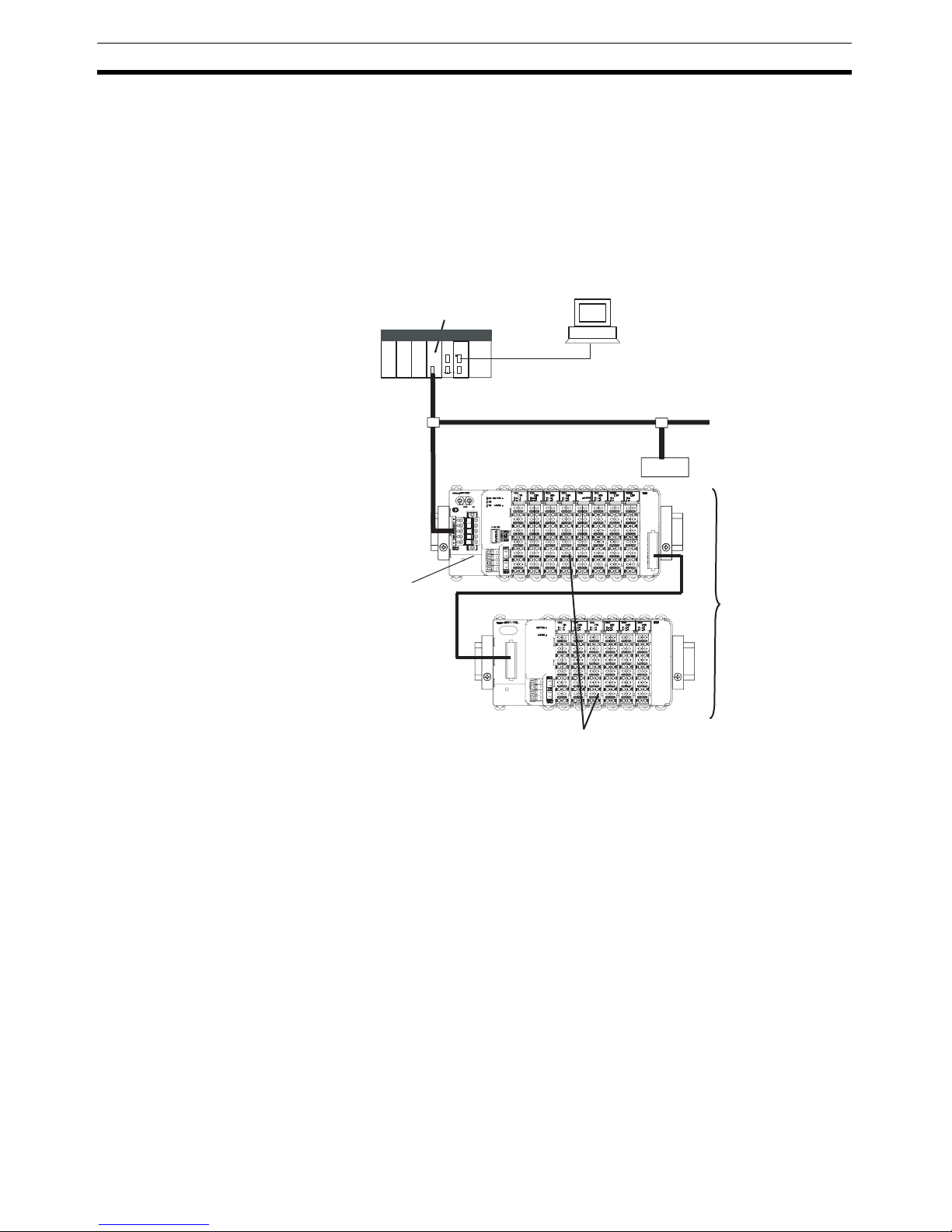
Simplified Startup The DeviceNet Communications Unit can be set up easily, just by wiring the
Unit, setting the DeviceNet node address on the Unit’s rotary switches, and
making simple DIP switch settings.
DeviceNet
PLC
Serial connection
(For setting, monitoring, and operating)
Slave
GRT1-DRT DeviceNet
Communications Unit
Slice I/O Units
Up to 64 Slice I/O Units can be connected to one DeviceNet Communications Unit.
Slice I/O Terminals
DeviceNet Master Unit
Page 22

3
Features and System Configuration Section 1-2
The Unit’s configuration is read automatically when the power is turned ON
and I/O is also automatically allocated in the Slice I/O Units. It is not necessary to make any settings with a special Programming Device.
Simplified I/O Wiring All of the Slice I/O Units that connect to a DeviceNet Communications Unit are
equipped with screw-less clamp terminal blocks. Wiring to external I/O is
accomplished just by inserting the wire into the terminals, eliminating the
need to tighten terminal screws.
Table Registration The configuration of the Slice I/O Units (mounting order and I/O size) con-
nected to a DeviceNet Communications Unit can be registered in a table simply by switching a pin on the DeviceNet Communications Unit’s DIP switch.
Once the table has been registered, the actual configuration is compared to
the registered configuration each time that the power is turned ON. If the configuration does not match, a status flag can be turned ON in the DeviceNet
Master to indicate the error.
Communications Error
History Monitor
The communications error history in the DeviceNet Communications Unit can
record the four most recent communications errors in the DeviceNet network
and the 64 most recent Slice I/O Terminal errors. The communications error
information (communications error cause code and communications power
supply voltage when error occurred) can be read with an explicit message
command or from the Configurator.
Online Replacement of I/O
Units
The Slice I/O Unit’s circuit section can be removed, so it isn’t necessary to
turn OFF the power to replace a Unit. Communications can be maintained in
the remaining (connected) Units.
Parameter Backup and
Restore
Before replacing a Slice I/O Unit for maintenance, the parameter data set in
the I/O Unit can be backed up in the DeviceNet Communications Unit by
switching a pin on the Communications Unit’s DIP switch. After the I/O Unit
has been replaced, another DIP switch operation can be used to select the
mode that automatically writes the backed-up parameter data to the appropriate Units.
Automatic Baud Rate
Recognition
The DeviceNet Communications Unit automatically detects the Master’s communications baud rate, so it isn’t necessary to set the baud rate. (If the Master’s baud rate has been changed, the DeviceNet Communications Unit must
be turned OFF and then ON again to change its baud rate.)
Network Power Supply
Volt a g e M onito r
The DeviceNet network’s power supply voltage values (present, maximum,
and minimum values) are recorded in the DeviceNet Communications Unit.
The Configurator can be used to read the recorded information. Furthermore,
a warning voltage level can be set in the DeviceNet Communications Unit in
order to notify the Master if the voltage drops below that preset warning level.
Unit Power ON Time
Monitor
This function records the total time that the DeviceNet Communications Unit's
internal circuit power has been ON. The Configurator or explicit messages
can be used to read the information. Furthermore, a warning voltage level can
be set in the DeviceNet Communications Unit in order to notify the Master if
the set warning time is exceeded.
Unit Comment A user-set name can be assigned to each DeviceNet Communications Unit
and recorded in the Unit. When making settings or monitoring operation, the
comments make it easy to identify individual Units based on their application
or location.
Page 23
4
Specifications Section 1-3
Last Maintenance Date The dates on which maintenance is performed can be written to the
DeviceNet Communications Unit. The recorded date shows when maintenance is required next.
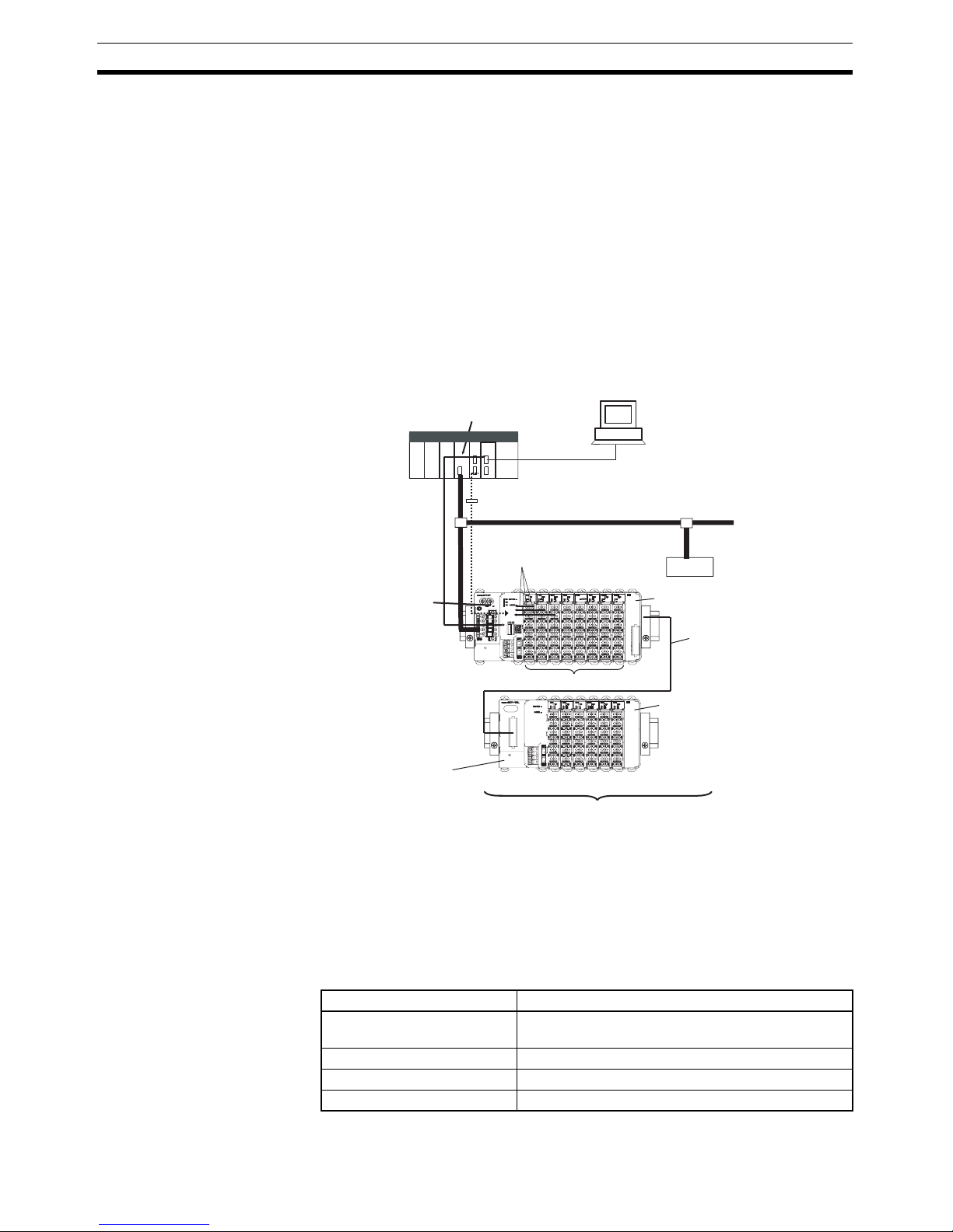
1-2-2 System Configuration
The DeviceNet Communications Unit connects to the Master by a network
cable and it connects to the Slice I/O Units by directly coupling the Units with
slide connectors.
The I/O Unit data in the DeviceNet Communications Unit is shared with the
Master’s Input and Output Areas through the DeviceNet network. The I/O
Units’ data is collected in the DeviceNet Communications Unit and exchanged
with the Master asynchronously.
It is also possible to send explicit message commands addressed to the
DeviceNet Communications Unit.
Note Always install an End Unit on the last I/O Unit in the last node.
1-3 Specifications
1-3-1 Communications Specifications
CS/CJ-series DeviceNet Unit (master)
DeviceNet
PLC
Serial connection
(For setting, monitoring, and operating)
CX-One (CX-Integrator)
Explicit messages
Used to monitor operation and write
parameters to the Slice I/O Units or
DeviceNet Communications Unit.
Remote I/O communications
I/O data is collected from
the connected Slice I/O
Units and exchanged in a
batch with the Master.
I/O data first goes to the
Communications Unit.
Slave
GRT1-DRT DeviceNet
Communications Unit
I/O Units
GRT1-TBR Right Turnback Unit
GRT1-TBL Left Turnback Unit
GCN2-100 Turnback Cable (1 m)
GRT1-END End Unit
Up to 64 Slice I/O Units can be connected to one DeviceNet Communications Unit.
Up to 2 sets of Turnback Units
can be used per Communications Uni
t
Item Specification
Number of connectable Slice
I/O Units
64 Units max.
Baud rate 3 Mbps
Communications signal level RS-485
Turnback Cable Length 1 m max., up to 2 cables can be connected.
Page 24

5
Specifications Section 1-3
1-3-2 General Specifications
1-3-3 DeviceNet Communications Unit Specifications
Total number of I/O points 1,024 points max. (128 bytes)
(combined total for inputs and outputs)
Slice I/O Terminal connections
Building-block style configuration with slide connectors (Terminals connect with Turnback Cables.)
Baseblock power supply Voltage: 24 V DC
Current: 4 A
Event messaging Supported.
Item Specification
Item Specification
Ambient operating temperature
−10 to 55°C (with no icing or condensation)
Ambient operating humidity 25% to 85%
Ambient storage temperature −25 to 65°C (with no icing or condensation)
Noise immunity Conforms to IEC 61000-4-4, 2.0 kV
Vibration resistance 10 to 60 Hz: 0.7 mm double amplitude
60 to 150 Hz: 50 m/s
2
Shock resistance
150 m/s
2
Withstand voltage 500 VAC (between isolated circuits)
Enclosure rating IP20
Item Specification
Model number GRT1-DRT
Number of I/O points 1,024 points max. (128 bytes)
(combined total for inputs and outputs)
Number of connectable Units 64 Slice I/O Units max.
Slice I/O Unit unit numbers 1 to 64 (assigned automatically)
Slice I/O Unit data size 0, 2, or 4 bits
0 to 16 words (complete words)
Status flags Use 1 word (for Communications Unit status flags)
Parameter backup and restore Can back up and restore up to 2 KB of data per Unit.
Network
power
supply
Voltage 11 to 25 V DC
Current 22 mA
Inrush current 6 A max. (at cold start)
I/O power supply Voltage: 24 V DC
Current: 4 A
Indicators MS (Two-color
LED)
Indicates the DeviceNet Communications Unit’s
operating status
NS (Two-color
LED)
Indicates the host communications (DeviceNet) status.
TS (Two-color
LED)
Indicates the Slice I/O Terminal’s operating status
PWR (One-color
LED)
Indicates the Unit power supply status
IO PWR (Onecolor LED)
Indicates the I/O power supply status
Page 25

6
List of Available Units Section 1-4
1-4 List of Available Units
The following table shows the Units that can be used in Slice I/O Terminals as
well as the devices that can be connected. Refer to the GRT1 Series Slice I/O
Units Operation Manual for details, such as Slice I/O Unit specifications.
Switches Node-address
setting switches
Decimal rotary switches
Set the Unit’s node address as a DeviceNet Slave.
Other switches DIP switch
Pin 1: Create/Enable registered table (Switch from
OFF to ON to register the table. Leave ON to enable
the table.)
Pin 2: Always OFF.
Pin 3: Automatic restore (Auto-restore enabled when
ON.)
Pin 4: Backup trigger (Switch from OFF to ON two
times to backup the parameter data.)
Connector One open connector for DeviceNet, with screws
The XWG4-05C4-TF-D Multi-drop Connector can be
connected.
Terminals Two terminals for I/O power supply
Two terminals for Unit power supply
Power consumption 3 W
Power consumption per block 80 W max. (Unit power supply)
(If more than 80 W is required, separate into blocks
using Turnback Units.)
Block separation Basic block plus up to two other blocks
I/O current consumption 4 A max.
Weight 137 g
Accessories XW4G-05C4-TF-D Connector
For multi-drop node connection. Connector screws
provided.
Item Specification
Model
number
Specifications
GRT1-DRT DeviceNet Communications Unit (Up to 64 I/O Units can be con-
nected.)
GRT1-ID4 Slice I/O Unit with 4 DC inputs (NPN)
GRT1-ID4-1 Slice I/O Unit with 4 DC inputs (PNP)
GRT1-OD4 Slice I/O Unit with 4 DC outputs (NPN)
GRT1-OD4-1 Slice I/O Unit with 4 DC outputs (PNP)
GRT1-ROS2 Slice I/O Unit with 2 relay outputs
GRT1-AD2 Slice I/O Unit with 2 analog inputs
GRT1-DA2V Slice I/O Unit with 2 voltage analog outputs
GRT1-DA2C Slice I/O Unit with 2 current analog outputs
GRT1-END End Unit
GRT1-PD2 I/O Power Supply Unit
GRT1-TBR Right Turnback Unit (Mounts to the right side of I/O Terminal.)
GRT1-TBL Left Turnback Unit (Mounts to the left side of I/O Terminal.)
GCN2-100 Turnback Cable (1 m)
Page 26

7
Basic Operating Procedure Section 1-5
1-5 Basic Operating Procedure
The following procedure shows the basic steps required before using the Slice
I/O Terminals.
Operating Procedure
1,2,3... 1. Connect the DeviceNet Communications Unit to the Master and connect
the desired Slice I/O Units.
2. Turn ON the power supply to the DeviceNet Communications Unit.
3. Turn ON (from OFF to ON) pin 1 of the DIP switch on the front of the DeviceNet Communications Unit. When pin 1 is turned ON, the existing Slice
I/O Unit configuration (connection order and I/O size) is registered in the
DeviceNet Communications Unit as a registered table. (After the table is
registered, leave pin 1 ON to enable the table.)
4. The next time that the power is turned ON, the connected Slice I/O Unit
configuration at that moment is automatically compared to the registered
table and any Slice I/O Units that do not match the registered table (connection order or I/O size) will not participate in I/O communications. I/O
communications will start with the other Slice I/O Units.
Note (1) When a communications error has occurred, the DeviceNet Communica-
tions Unit’s TS indicator will flash red and the affected Slice I/O Unit’s TS
indicator will flash red. At the same time, the error code and error details
code will be stored in the DeviceNet Communications Unit’s error history.
(2) For details on the operating procedures, refer to SECTION 4 Setup and
Operating Procedures.
Page 27

8
Basic Operating Procedure Section 1-5
Page 28

9
SECTION 2
Component Names and Functions
This section describes the names and functions of the components in the DeviceNet Communications Unit.
2-1 Nomenclature and Dimensions . . . . . . . . . . . . . . . . . . . . . . . . . . . . . . . . . . . . 10
2-1-1 LED Indicators . . . . . . . . . . . . . . . . . . . . . . . . . . . . . . . . . . . . . . . . . 11
2-1-2 Switch Settings . . . . . . . . . . . . . . . . . . . . . . . . . . . . . . . . . . . . . . . . . 13
2-2 Node Address Settings and I/O Allocation. . . . . . . . . . . . . . . . . . . . . . . . . . . 14
2-2-1 Setting the Node Address . . . . . . . . . . . . . . . . . . . . . . . . . . . . . . . . . 14
2-2-2 Unit Numbers of Slice I/O Units (Automatically Allocated) . . . . . . 15
2-2-3 I/O Allocation to the Slice I/O Terminal’s Master Unit . . . . . . . . . . 16
2-2-4 I/O Allocation with the Configurator (Ver. 2.@ or Higher) . . . . . . . 20
2-3 Unit Functions. . . . . . . . . . . . . . . . . . . . . . . . . . . . . . . . . . . . . . . . . . . . . . . . . 23
2-3-1 Table Registration Function . . . . . . . . . . . . . . . . . . . . . . . . . . . . . . . 24
2-3-2 Backup Function. . . . . . . . . . . . . . . . . . . . . . . . . . . . . . . . . . . . . . . . 26
2-3-3 Automatic Restore Function. . . . . . . . . . . . . . . . . . . . . . . . . . . . . . . 26
2-3-4 Online Replacement Function . . . . . . . . . . . . . . . . . . . . . . . . . . . . . 28
2-3-5 Automatic Baud Rate Recognition . . . . . . . . . . . . . . . . . . . . . . . . . . 29
2-3-6 Network Power Supply Voltage Monitor . . . . . . . . . . . . . . . . . . . . . 29
2-3-7 Unit Conduction Time Monitor . . . . . . . . . . . . . . . . . . . . . . . . . . . . 30
2-3-8 Unit Comments. . . . . . . . . . . . . . . . . . . . . . . . . . . . . . . . . . . . . . . . . 32
2-3-9 Network Communications Error History Monitor . . . . . . . . . . . . . . 34
2-3-10 I/O Communications Error History Monitor . . . . . . . . . . . . . . . . . . 35
2-3-11 Last Maintenance Date . . . . . . . . . . . . . . . . . . . . . . . . . . . . . . . . . . . 37
Page 29
10
Nomenclature and Dimensions Section 2-1
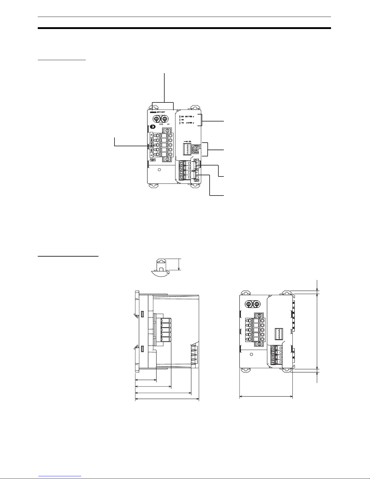
2-1 Nomenclature and Dimensions
Nomenclature
Dimensions (mm)
DIP Switch
Sets the I/O allocation method and registers the I/O Unit
configuration information.
SW1 (REGS): Create/enable registration table.
SW2 (I/O): Always OFF
SW3 (ADR): Automatic restore
SW4 (BACK): Backup trigger
Rotary switches
Set the Unit's node address as a DeviceNet
Slave. Set a decimal node address between
0 and 63.
DeviceNet communications connector
Connect the DeviceNet network's
communications cable to this connector.
Indicators
Unit power supply terminals
Connect the power supply for the Unit's internal circuits and
the connected Slice I/O Units' internal circuits.
I/O power supply terminals
Connect the power supply for the connected Slice I/O Units'
external I/O.
Refer to 2-1-1 LED Indicators for details.
24
40
62
70
58
3
84
12
3
Page 30
11
Nomenclature and Dimensions Section 2-1
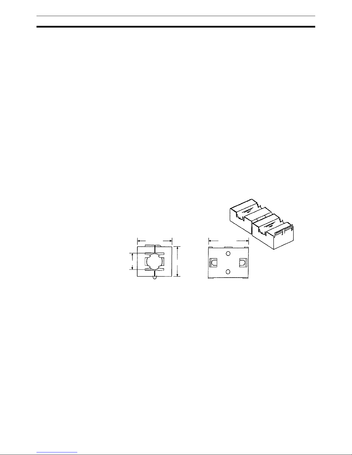
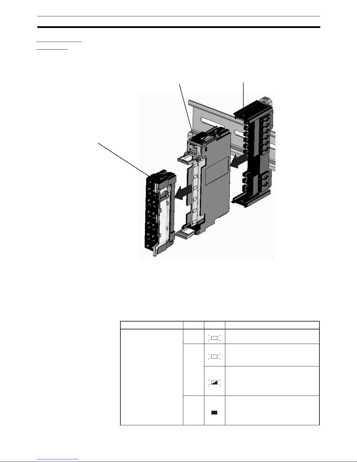
Slice I/O Unit
Structure
The Slice I/O Unit is made up of three blocks, as shown in the following diagram. When replacement is necessary, individual blocks can be replaced.
Note Refer to the GRT1 Series Slice I/O Units Operation Manual (W455) for details
such as Slice I/O Unit specifications and standard models.
2-1-1 LED Indicators
The DeviceNet Communications Unit’s LED indicators indicate the status of
the Unit, the DeviceNet network, and communications between the Unit and
Slice I/O Units.
Main Block
Base Block
This is the Slice I/O Unit's bus connector.
If a faulty Unit is being replaced, this
block can be left attached during online replacement.
Terminal Block
This is the Slice I/O Unit's terminal block.
If a faulty Unit is being replaced, the wiring can be
left attached and just the Main Block replaced.
Name Color Status Meaning
MS
DeviceNet Communica-
tions Unit status
Green Normal status (DeviceNet Communica-
tions Unit operating normally)
Red Non-recoverable, fatal error occurred.
• Watchdog timer error
• RAM error
Recoverable, non-fatal error occurred.
• EEPROM checksum error
• Parameter setting logic error
• EEPROM hardware error
--- No power
• The Unit’s power supply is OFF.
• The Unit is being reset.
• The Unit is waiting for initialization.
MS
MS
MS
MS
Page 31

12
Nomenclature and Dimensions Section 2-1
NS
DeviceNet network status
Green Unit is online with communications
established (normal network status).
Unit is online, but communications are
not established (waiting for communications from Master).
Red Fatal communications error occurred.
(Network communications are not possible.)
• Node address duplicated
• Bus Off error
Non-fatal communications error
occurred.
• Communications timeout
--- Offline or power OFF
• Waiting for completion of node
address duplication check by Master.
• Power is not being supplied to the
DeviceNet Communications Unit.
TS
Slice I/O Terminal com-
munications status
Green Communicating with I/O Unit (commu-
nications established).
I/O Unit joining system.
(Flashing once every 1 s)
Backup/Restore function operating.
(Flashing once every 0.5 s)
• Restoring settings to I/O Unit, backup
function operating
• Downloading I/O Unit settings.
Red Fatal communications error occurred.
Failure occurred while restoring settings to I/O Unit or downloading I/O
Unit settings.
(Lit for 2 s)
Non-fatal communications error
occurred.
• Communications timeout
• Verification error occurred with registered table.
• Different model Unit detected after I/O
Unit replacement.
--- • Power not being supplied.
• Communications haven’t started with
I/O Unit.
• Overcurrent detected.
UNIT PWR
Unit power supply status
Green 24 V is being supplied to the Unit
power supply.
Unit power supply is OFF.
IOPWR
External I/O power sup-
ply status
Red 24 V is being supplied to the I/O power
supply.
I/O power supply is OFF.
Name Color Status Meaning
NS
NS
NS
NS
NS
TS
TS
TS
TS
TS
TS
TS
MS
MS
MS
MS
Page 32

13
Nomenclature and Dimensions Section 2-1
2-1-2 Switch Settings
Note The DeviceNet Communications Unit detects the Master’s communications
baud rate automatically, so it is not necessary to set the baud rate.
Rotary Switches
Use the rotary switches to set the Unit’s DeviceNet node address between 00
and 63. (Do not set values 64 to 99.)
DIP Switch The DIP switch is used for the Unit settings and operations described below.
The DIP switch functions are only introduced here. For details, refer to 2-3
Unit Functions.
Create/Enable
Registration Table
(REGS, pin 1)
If pin 1 is turned from OFF to ON while the Unit’s power is ON, the existing
Slice I/O Unit configuration (connection order and I/O size) is registered in the
DeviceNet Communications Unit as a registered table.
If pin 1 is ON when the Unit’s power is turned ON, the actual Slice I/O Unit
configuration at startup is automatically compared to the registered table. Any
Slice I/O Units that do not match the registered table will not participate in
Slice I/O communications.
I/O Allocation Mode
(I/O, pin 2)
Always leave pin 2 set to OFF.
Automatic Restore
(ADR, pin 3)
When pin 1 is ON (r
egistered table enabled) and pin 3 is ON, parameter data is
automatically restored to the Slice I/O Units that had parameter data backed
up.
×10
DeviceNet
Node address setting
×1
0
1
2
3
4
5
6
7
8
9
0
1
2
3
4
5
6
7
8
9
ON
1
2
3
4
REGS
I/O
ADR
BACK
Switch setting Function
ON Registered table is enabled. (If there is a verification error, the
affected Unit will not participate in communications.)
OFF Registered table is disabled. (All Units participate in communica-
tions.)
OFF to ON Register I/O Unit table. (Of course, pin 1 must be turned OFF to
ON while the Unit is ON.)
ON to OFF Clear registered table.
Switch setting Function
ON Automatic restore function enabled (when pin 1 is ON).
OFF Automatic restore function disabled.
Page 33

14
Node Address Settings and I/O Allocation Section 2-2
Backup Trigger
(BACK, pin 4)
When pin 1 is ON (registered table enabled) and pin 4 is turned OFF to ON, the
parameter data of all connected Slice I/O Units is backed up in the Communications Unit.
Note The factory setting is OFF for all DIP switch pins.
2-2 Node Address Settings and I/O Allocation
I/O words in the Master (the CPU Unit’s I/O memory) are allocated to the Slice
I/O Terminal based on the DeviceNet Communications Unit’s node address
setting. Once the DeviceNet node address is set, I/O will be allocated to the
Slice I/O Terminal by default and remote I/O communications will start automatically.
Note When the power is turned ON, unit numbers are allocated automatically to the
Slice I/O Units in the Slice I/O Terminal.
2-2-1 Setting the Node Address
The Slice I/O Terminal’s node address as a DeviceNet Slave is set with the
rotary switches on the front of the DeviceNet Communications Unit. The node
address determines the starting word of the area allocated to the Slice I/O
Terminal.
Switch setting Function
ON Switch ON to OFF to ON to start the parameter backup (when pin
1 is ON).
OFF ---
ON OFF ON
1 s 1 s 1 s
The backup operation starts after pin 4 is turned
from ON to OFF to ON within 3 seconds.
DeviceNet
Master Unit
Set the first allocated
word with the node
address setting.
I/O memory
Slice I/O
Terminal
CPU Unit
The DeviceNet Communications
Unit's DeviceNet node address
setting determines the first word
of the I/O memory area allocated
in the CPU Unit.
DeviceNet
Communications Unit
Slice I/O Terminal
Page 34

15
Node Address Settings and I/O Allocation Section 2-2
DeviceNet Node Address
Setting
The left rotary switch sets the ten's digit, and the right rotary switch sets the
one's digit. Any number in the allowed range (00 to 63) can be set as long as
it is not set on another node (Master, Slave, or Configurator) in the network.
Note (1) Always turn OFF the DeviceNet communications power supply and De-
viceNet Communications Unit’s power supply before setting the node address.
(2) The factory default setting for the node address is 00.
(3) If the node address is duplicated on another node, a node address dupli-
cation error will occur and the Unit will not be able to join the network.
2-2-2 Unit Numbers of Slice I/O Units (Automatically Allocated)
The numbers used to identify the Slice I/O Units in a Slice I/O Terminal are
called the Slice I/O Units’ unit numbers. These unit numbers are allocated
automatically from left to right starting from #1, when the power is turned ON.
It is not necessary for the user to set these numbers.
Note The unit numbers allocated automatically to the Slice I/O Units are unrelated
to the DeviceNet node address set with the rotary switches.
×10
×1
DeviceNet node
address setting
DeviceNet
Communications Unit
The Slice I/O Units' unit numbers are allocated
automatically in order, from left to right.
I/O
#1
I/O
#2
I/O #3I/O
#4
I/O
#64
:
:
Page 35

16
Node Address Settings and I/O Allocation Section 2-2
2-2-3 I/O Allocation to the Slice I/O Terminal’s Master Unit
The Slice I/O Terminal’s I/O data is allocated in the I/O memory of the CPU
Unit in which the Master Unit is mounted and the I/O memory location is
determined by the DeviceNet Communications Unit’s DeviceNet node
address.
The user can set the Slice I/O Terminal’s allocated data freely with a
DeviceNet Configurator.
E
Connected order
CPU Unit
CS/CJ-series
DeviceNet Unit
I/O memory
A
B
CD
E
DeviceNet
Communications
Unit
A
BC
D
Slice I/O Terminals (Slaves)
Data is allocated to I/O memory in the order
that the Units are connected, from lowest to
highest.
I/O Units with bit allocation are allocated data
from the rightmost to leftmost bit, in 2-bit units.
I/O Units with word allocations are allocated
data from the lower to higher word address.
0
8
16
Order of allocation
(1) Communications Unit status
(2) Each Slice I/O Unit's I/O data.
(3) Slice I/O Unit network
participation status.
Page 36

17
Node Address Settings and I/O Allocation Section 2-2
I/O Allocation
Example
I/O data is allocated to the I/O Units in the order that they are connected to the
Communications Unit, regardless of the I/O Units’ models. Unless special
allocation data settings are selected with the Configurator, data is allocated
from the first word starting with the Communications Unit’s status flags and
then the leftmost I/O Unit’s data.
Data in the Master’s input and output areas is allocated to the Slice I/O Units
based on their unit numbers.
Note I/O Units with bit allocation (such as the GRT1-ID4/OD4) are allocated data in
2-bit units. I/O Units with word allocation (such as the GRT1-AD2) are allocated data in 1-word units. The following example shows the allocation to an
Output Unit.
Allocated Data
Patterns
The following kinds of data can be allocated in the Master. The Configurator
can be used to freely select the kinds/combination of data allocated. If the
Configurator isn’t used to select the data pattern, the default setting is used,
which is I/O data + Communications Unit status flags (pattern number 1 in the
following table).
Data Allocated to Master
Note The Communications Unit’s status flags and Slice I/O Units’ communications
participating/withdrawn flags cannot be allocated in the output area.
+2
+3
#4
+1
Word
15 8
0
#1 #3 #2
#6
Word
15 8
0
#5
#2
ID4
#3
ID4
#4
AD2
#5
OD4
#1
ID4
#6
ROS2
Some areas may be unused
when data is allocated.
Communications
Unit
Communications Unit status
Unused
First word
First word Unused
Output area
Input area
#2
OD4
#3
OD4
#4
ROS
2
#5
OD4
#1
OD4
#6
DA2
+1
+2
#6
+0
Word
#1
+3
#5
#2 #3
#4 #5
Communications
Unit
Data is allocated in 2-bit units
to I/O Units that require 4 bits,
so there may be unused areas
as shown in the following table.
Unused
Slice I/O Terminal configuration
15
8
0
Allocated data pattern
1 I/O data (inputs) + Communications Unit status flags
2 I/O data (inputs and outputs) only
3 Communications Unit status flags only
4 Slice I/O Unit communications participating/withdrawn flags only
Page 37

18
Node Address Settings and I/O Allocation Section 2-2
Allocated Data Size
Note When allocating data, be sure that it does not exceed the maximum that can
be allocated (64 words).
Status Flags The status flags can be allocated in the Master independently or together with
the I/O data. There are two kinds of status flags, the Communications Unit’s
status flags and I/O Units’ communications participating/withdrawn flags, and
these status flags must be allocated in separate areas.
Communications Unit’s
Status Flags
These flags can be used to monitor the status of the connection with the Master and the status of Slice I/O Units connected to the Communications Unit.
The status flags take up 2 words and the information is transferred to the Master.
With the default data pattern (pattern 1), these status flags are allocated in the
Master together with the I/O data. The status flags can also be read with the
Configurator or an explicit message command.
Data type Data size
I/O data (input and output) When only the actual I/O data is allocated:
64 input words max. or 64 output words max.
The GRT1-ID4(-1) and GRT1-OD4(-1) use 4 bits
per Unit.
The GRT1-ROS2 uses 2 bits.
Communications Unit status flags 1 word
Slice I/O Unit communications
participating/withdrawn flags
Participating flags: 4 words
Withdrawn flags: 4 words
Total: 8 words
I/O data (inputs) + Communications Unit status flags
Amount of I/O data being used + 1 word
Bit Content Description
0 Slice I/O Bus Communications Error Flag Monitors the status of Slice I/O Terminal communications.
1 Reserved ---
2 Slice I/O Unit Warning Flag
0: Normal; 1: Error detected
Indicates a major Slice I/O Unit error. This flag goes ON when
there is an error in any one of the connected Slice I/O Units.
3 Reserved ---
4 Slice I/O Unit Alarm Flag
0: Normal; 1: Error detected
Indicates a minor Slice I/O Unit error. This flag goes ON when
there is an error in any one of the connected Slice I/O Units.
Status flags (16 bits)
Master CPU Unit
DeviceNet
Communications Unit
First word
I/O data (4 bits)
Status flags
Slice I/O Unit (4 inputs)
Input Area
Page 38

19
Node Address Settings and I/O Allocation Section 2-2
Slice I/O Unit
Participating/Withdrawn
Flags
These flags can be used to monitor the connection status (participating or
withdrawn) of the Slice I/O Units connected to the Communications Unit.
There are always 8 words allocated to the Participating/Withdrawn Flags (4
words for the Participating Flags and 4 words for the Withdrawn Flags),
regardless of the number of I/O Units that are connected.
These flags are not allocated in the Master by default. The flags must be allocated with the Configurator.
These flags can be read with the Configurator or an explicit message command.
Note (1) Each bit corresponds to the unit number of a connected Slice I/O Unit.
(Up to 64 Units can be monitored.)
(2) Each Unit’s status can also be monitored with the TS indicator on the front
of the I/O Unit.
5 Reserved ---
6 Reserved ---
7 Reserved ---
8 Reserved ---
9 Reserved ---
10 Reserved ---
11 Network Power Supply Voltage Monitor
Error Flag
0: Normal; 1: Error (monitor value reached)
Monitors the network power supply voltage using the voltage
threshold set with the network power supply voltage monitor
function.
12 Unit Maintenance Flag
0: Normal; 1: Error (monitor value reached)
Monitors the Unit’s operating time the power ON time threshold set with the Unit power ON time monitor function.
13 Automatic Restore Monitor Flag
0: Restore successful; 1: Restore failed
Indicates whether or not the automatic parameter restoration
to the Slice I/O Units was completed properly. This flag will be
ON if the restore operation failed and OFF if data was restored
properly to all Units.
14 Communications Unit Error Flag
0: Normal; 1: Error occurred
This is the overall Unit status flag. This flag will be ON if any
one of the other flags (bits 0 to 13) is ON.
15 I/O Refreshing Flag
0: I/O communications stopped
1: I/O communications normal
Indicates whether I/O data is being exchanged normally.
Bit Content Description
Table name Description
Participating table ON: Participating (properly allocated to Master)
OFF: Not participating (An I/O Unit will not join communications if the registered table is enabled and a verification error
occurred with the Unit.)
Withdrawn table ON: Communications error occurred or the Unit was with-
drawn after participating in communications.
OFF: Never joined communications or participating normally.
15 Bit 14 Bit 13 Bit 12 Bit 11 Bit 10 Bit 9 Bit 8 Bit 7 Bit
5 Bit 4 Bit 3 Bit 2 Bit 1 Bit
0 Bit
0
16 15 14 13 12 11 10 9 8 7 6 5 4 3 2
1
+1
32 31 30 29 28 27 26 25 24 23 22 21 20 19 18
17
+2
48 47 46 45 44 43 42 41 40 39 38 37 36 35 34
33
+3
64 63 62 61 60 59 58 57 56 55 54 53 52 51 50
49
+4
16 15 14 13 12 11 10 9 8 7 6 5 4 3 2
1
+5
32 31 30 29 28 27 26 25 24 23 22 21 20 19 18
17
+6
48 47 46 45 44 43 42 41 40 39 38 3 36 35 34
33
+7
64 63 62 61 60 59 58 57 56 55 54 53 52 51 50
49
Participating
table
Withdrawn
table
6 Bit
Page 39

20
Node Address Settings and I/O Allocation Section 2-2
2-2-4 I/O Allocation with the Configurator (Ver. 2.@ or Higher)
The following procedure shows how to use the Configurator to select and allocate particular I/O data or status flags in the Master instead of using the
default settings.
Allocating I/O Data
from the Master Unit
1,2,3... 1. In the Master’s Edit Device Parameters Window, select the DeviceNet
Communications Unit to be set, and specify the connection in the Advanced Setting Window. Select the I/O data (pattern) in the connection
path setting.
2. In the Master’s Edit Device Parameters Window, allocate Slave I/O.
Note For details on connections and connection paths, refer to Appendix
B DeviceNet Connections in the DeviceNet Units Operation Manual
(W380).
The following setting example shows how to allocate 4 inputs + Communications Unit status flags as the data.
Example: 4 inputs + 4 inputs + Status flags
Procedure
1,2,3... 1. In the Network Configuration Window, select the Master Unit, and double-
click or click the right mouse button and select Parameter – Edit – General, and then select the Smart Slave to be set.
Bits 15 8 0
CIO 3300
Communications Unit status flags
CIO 3301 Unused
4 inputs 4 inputs
Page 40

21
Node Address Settings and I/O Allocation Section 2-2
2. Click the Advanced Setup Button, click the Connection Tab, and select
User Setup. Select Use Poll Connection and Use COS Connection and
then select output data, input data, and generic status for the respective
connection paths. In this example, the IN size for COS connection is set to
generic status, the IN size for poll connection is set to input data, and
OUT size for poll connection is set to output data.
3. Click the OK Button.
Note If there are checks in the check boxes but the connection path settings are left
blank, the following settings will be made automatically.
IN (Smart Slave to Master Unit) OUT (Master Unit to Smart Slave)
Poll Input Data + Generic Status Output Data
Bit-Strobe Input Data + Generic Status Not set.
COS Input Data + Generic Status Not set.
Cyclic Input Data + Generic Status Not set.
Page 41

22
Node Address Settings and I/O Allocation Section 2-2
4. Click the I/O Allocation (IN) Tab and edit the I/O allocations.
Select the Smart Slave to be set and click the Edit Button to display the
Edit I/O Allocate Window.
Set the Poll settings (indicates input data) to block 1, allocated 3300.
Set the COS settings (indicates generic data) to block 2, allocated 3500.
5. Click the OK Button.
Page 42

23
Unit Functions Section 2-3
6. In the same way as above, click the I/O Allocation (OUT) Tab and edit the
I/O allocations. Set to block 1, allocated 3200.
7. Return to the General Tab Page and click Download.
Note When Auto allocation as is registered. is selected in the General Tab Page,
each time the connection path is set, a message will be displayed indicating
that the current I/O allocations have been deleted because the connection
has been changed. To set the connection path, deselect Auto allocation as is
registered. before registering the Slaves.
2-3 Unit Functions
Function List The following table lists the DeviceNet Communications Unit’s functions.
Function name Summary Setting/monitoring method
Table registration Reads the configuration of the Slice I/O Units connected to the
Communications Unit and registers that information in a table.
Set with DIP switch.
Backup Records the parameter data of all connected I/O Units in the Com-
munications Unit.
Set with DIP switch.
Automatic restore Automatically downloads the backed-up parameter data to the
appropriate Unit.
Set with DIP switch.
Online replacement I/O Units can be replaced without turning the power OFF. No setting required.
Automatic baud rate
recognition
The Master's communications baud rate is automatically detected
and adopted.
No setting required.
Network power supply voltage monitor
The DeviceNet network's power supply voltage values are
recorded in the DeviceNet Communications Unit.
Set/read with Configurator or
explicit message.
Unit power ON time
monitor
Records the total time that the DeviceNet Communications Unit's
internal circuit power has been ON.
Set/read with Configurator or
explicit message.
Unit comment A user-set name can be assigned to the Communications Unit. Set/read with Configurator or
explicit message.
Network communications error history
A communications error history from the viewpoint of the Communications Unit can be collected in the Communications Unit.
Set/read with Configurator or
explicit message.
Page 43

24
Unit Functions Section 2-3
2-3-1 Table Registration Function
Function Overview This function registers the configuration of the Slice I/O Units connected to the
DeviceNet Communications Unit in a table within the Unit, so that the registered I/O table can be automatically compared with the actual configuration
each time that the power is turned ON. The configuration is registered simply
by turning ON (OFF to ON) pin 1 of the DeviceNet Communications Unit’s DIP
switch while the Slice I/O Terminal’s power supply is ON. The registered table
is enabled if pin 1 is ON when the power is turned ON. If pin 1 is OFF when
the power is turned ON, the registered table is disabled and the Communications Unit will automatically detect the actual I/O configuration and start communications.
Creating a New
Registration Table
The Slice I/O Terminal’s present I/O configuration can be read and registered
in the table just by turning DIP switch pin 1 (REGS) from OFF to ON while the
DeviceNet Communications Unit’s power supply is ON. If the registration table
is being refreshed, the old registration table will be erased.
Note The configuration information shows the order that the Slice I/O
Units are connected and the I/O size (input or output, number of
bits) of each Slice I/O Unit. The I/O Unit model numbers are not recorded.
I/O communications
error history
A history of communications errors with connected I/O Units can
be collected in the Communications Unit.
Set/read with Configurator or
explicit message.
Last maintenance
date
The date on which maintenance was performed can be written to
the Communications Unit.
Set/read with Configurator or
explicit message.
Function name Summary Setting/monitoring method
Power ON
Turn pin 1 from
OFF to ON with
the power ON.
Registration table
Reads the configuration information, creates
the re
g
istration table, and records the table.
4
contact
inputs
DeviceNet
Communications
Unit
Figure 1
#1
#2 #3 #4
4
contact
inputs
4
contact
outputs
2
relay
outputs
Page 44

25
Unit Functions Section 2-3
Comparison with the
Registered Table
When DIP switch pin 1 (REGS) is ON and an I/O configuration table has been
registered in the Communications Unit, the actual I/O configuration is automatically compared to the registered table when the power is turned ON. A
verification error will occur if a registered I/O Unit cannot join I/O communications or an unregistered I/O Unit is detected.
If there are verification errors, the affected Slice I/O Units will not join in I/O
communications. I/O communications will start with the other Slice I/O Units.
■ Example of Comparison between Figure 1 and Figure 2
Note (1) Register the I/O configuration table when all of the Slice I/O Units are
communicating, i.e., when the DeviceNet Communications Unit’s TS indicator is lit green.
(2) A mismatch (verification error) with the registered table is indicated at the
DeviceNet Communications Unit’s TS indicator (flashing red) and can be
read from the Configurator. The error details can be read from the Configurator or the error history can be read with an explicit message command.
#1
#2
#3
#4
#1
#2
#3
#4
From left
Mismatch
I/O
Input
Input
Output
Output
Bits
4
4
4
2
Registered table
Actual configuration
From left
I/O
Input
Input
Output
Output
Bits
4
4
2
2
There are the same number of
Units, but the I/O data size does
not match, so a verification error
occurs and this I/O Unit does not
join in communications.
#1
#2 #3 #4
Pin 1 ON when power
was turned ON.
Registration table
The actual configuration is compared to the registered table.
Units that do not match the registered table do not participate
in I/O communications. I/O communications start with the other
I/O Units.
Four
contact
inputs
Figure 2
Four
contact
inputs
Tw o
relay
outputs
Tw o
relay
outputs
DeviceNet
Communications
Unit
Page 45

26
Unit Functions Section 2-3
2-3-2 Backup Function
Function Overview The backup function records the parameter data of all Slice I/O Units con-
nected to the DeviceNet Communications Unit. The parameter data recorded
in the Communications Unit can be restored to the Slice I/O Units later with
the automatic restore function when a Slice I/O Unit has been replaced.
Backup Procedure
1,2,3... 1. Verify that the power is ON, DIP switch pin 1 (REGS) is ON, and all of the
Slice I/O Units are participating in I/O communications.
2. Turn DIP switch pin 4 (BACK) ON, then OFF, and then ON again within 3 s
to start the back up.
3. While the data is being backed up, the DeviceNet Communications Unit’s
TS indicator will flash green every 0.5 s. The TS indicator will stop flashing
(not lit) when the backup is completed. If the restore operation fails, the TS
indicator will be lit red for 2 s.
Note (1) Do not turn OFF the power supply or reset the Configurator while data is
being backed up. The data will not be backed up properly if the power is
turned OFF.
(2) The backup data will be erased along with the registered I/O configuration
table if the power supply is turned ON or the Slave is reset while DIP
switch pin 1 (REGS) is turned OFF.
(3) We recommend backing up the parameter data in case a Unit fails in the
future.
2-3-3 Automatic Restore Function
Function Overview When a Slice I/O Unit has been replaced, this function will automatically
download (restore) Slice I/O Unit parameter data that was previously backed
up in the DeviceNet Communications Unit. The following conditions are
required to execute the automatic restore function:
• DIP switch pin 1 (REGS) was ON when the power was turned ON, so the
registered table is enabled.
• DIP switch pin 3 (ADR) was ON when the power was turned ON, so the
automatic restore function is enabled.
• Parameter data has been backed up in the DeviceNet Communications
Unit.
DeviceNet
Communications
Unit
Turn pin 4 ON, OFF, and
then ON again while the
power is ON and pin 1 is ON.
Downloads all of the I/O Units' unit
information and
p
arameter data.
#1
#2 #3 #4
Power ON
Page 46

27
Unit Functions Section 2-3
Preparation for Data
Restoration
1,2,3... 1. Create backup data in the Communications Unit with the backup function.
For details, see 2-3-2 Backup Function.
2. Turn ON DIP switch pin 3 (ADR).
Unit Replacement
Procedure
1,2,3... 1. Turn OFF the Slice I/O Terminal’s power supply and the I/O power supply.
2. Release the hook on the front of the I/O Unit that you want to replace and
remove the terminal block. The wiring can remain connected.
3. Remove the main block of the Slice I/O Unit and replace it with a new I/O
Unit.
4. Mount the terminal block that was removed in step 2 and latch the hook
that was released.
5. When the power is turned ON again, the Communications Unit will automatically detect the Unit that was replaced and download the backup data.
The I/O Unit’s TS indicator will indicate the results of the restore operation.
• If the download was successful, the Unit will be reset automatically and
join I/O communications normally. The I/O Unit’s TS indicator will be lit
green.
• If the download failed, the I/O Unit’s TS indicator will be flash red.
• If the connected Unit is the wrong model, the I/O Unit’s TS indicator will be
lit red.
Note (1) Do not turn OFF the power supply or reset the Configurator while data is
being restored. The data will not be restored up properly if the power is
turned OFF.
(2) When an I/O Unit has been replaced with the power ON and the new I/O
Unit joins I/O communications, the new Unit will be compared to the previous one and the parameter data restore operation will start automatically. While data is being restored, the DeviceNet Communications Unit’s TS
indicator will flash green every 0.5 s. The TS indicator will stop flashing
(not lit) when the restore operation is completed. If the restore operation
fails, the Automatic Restore Monitor Flag (bit 13 of the Communications
Unit status flags) will be turned ON and the Communications Unit’s TS indicator will be lit red for 2 s.
DeviceNet
Communications
Unit
Pin 1 was ON when power
is turned ON and pin 3 is
turned from OFF to ON.
Parameter data is automatically restored only
to the replacement Unit (same unit number,
same model number, different serial number).
Parameter data
Power ON
#1
#2 #3 #4
Page 47

28
Unit Functions Section 2-3
2-3-4 Online Replacement Function
Function Overview When one of the Slice I/O Units connected to the DeviceNet Communications
Unit must be replaced, the Unit can be replaced without turning OFF the
power. The Units can be replaced online because the Slice I/O Units are
made up of 3 blocks: the base block, main block, and terminal block. When
replacing a Slice I/O Unit, leave just the base block connected and replace the
main block. I/O communications will continue with the other I/O Units even
while the problem Unit is being removed and replaced.
Replacement Procedure
1,2,3... 1. Turn OFF the I/O power supply of the I/O Unit being replaced.
2. Release the hook on the front of the I/O Unit that you want to replace and
remove the terminal block. The wiring can remain connected.
3. Remove the main block of the Slice I/O Unit and replace it with a new I/O
Unit.
4. Mount the terminal block that was removed in step 2 and latch the hook
that was released.
5. Turn ON the I/O power supply.
Note (1) When a Unit withdraws from I/O communications during replacement, the
corresponding Slice I/O Unit Communications Withdrawn Flag will go ON
and the DeviceNet Communications Unit’s TS indicator will flash red.
(2) Before using the automatic restore function, the preparation for automatic
restoration (creating backup data and turning ON DIP switch pin 3) must
be completed. See 2-3-3 Automatic Restore Function for details.
(3) Always turn OFF the I/O Unit’s I/O power supply before replacement in
order to prevent false output signals, false input signals, and electrical
shocks. In addition, if external power is supplied to the terminal block for
a Unit such as a Relay Output Unit, turn OFF that power supply before
replacing the Unit.
(4) Only replace one I/O Unit at a time.
(5) Always replace the I/O Unit with the same model of I/O Unit. If a Unit is
replaced with a different model, there may be unexpected outputs and the
restore operation may not be completed properly.
(6) If the base block is faulty or damaged, turn OFF the power supply and re-
place the entire Unit. Even in this case, the I/O Unit’s parameter data will
be restored automatically if the automatic restore function is enabled
when the power is turned ON.
To keep the system online, leave the
communications block connected.
Unit being
replaced
If pin 1 and pin 3 are ON,
data is automatically restored
to the replaced Unit.
Power ON
DeviceNet
Communications
Unit
#1
#2
#3
#4
Page 48

29
Unit Functions Section 2-3
2-3-5 Automatic Baud Rate Recognition
The DeviceNet Communications Unit’s baud rate is automatically adjusted to
match the Master's baud rate. The Communications baud rate is set and
saved after the power is turned ON and communications with the Master are
established. The baud rate setting is retained until the next time that the
power is turned ON.
Note If the Master’s baud rate has been changed, the DeviceNet Communications
Unit must be turned OFF and then ON again to change its baud rate.
2-3-6 Network Power Supply Voltage Monitor
Function Overview The present, bottom, and peak values of the Network power voltage can be
recorded in the DeviceNet Communications Unit. A monitor voltage level can
be set with the Configurator and recorded in the DeviceNet Communications
Unit. The Network Power Voltage Error Flag in the Status Area will be turned
ON when the voltage drops below the set monitor value. The current, minimum, and maximum values of the Network power voltage, and the Network
Power Voltage Error Flag can be read from the Configurator.
Note 1. The communications power voltage of the actual DeviceNet is 11 V mini-
mum, so if the communications power voltage drops below 11 V, the operation for reading the measurement values using the Configurator may not
function properly.
2. The maximum and minimum Network power voltages are cleared when the
Network power is turned OFF.
Setting Using the
DeviceNet
Configurator
The method used to set values from the DeviceNet Configurator (Ver. 2.43 or
later) is described here.
1,2,3... 1. Turn ON the DeviceNet Communications Unit’s power supply.
2. From the Main Window, open the Network Configuration Window and double-click or click the right mouse button over the icon of the DeviceNet
Communications Unit to be set. Select Parameter and Edit to display the
Edit Device Parameters Window.
From the Maintenance Mode Window, click the right mouse button over the
icon of the DeviceNet Communications Unit to be set. Select Parameter
and Edit to display the Edit Device Parameters Window.
Page 49

30
Unit Functions Section 2-3
3. Select the General Ta b.
4. Enter the desired value in the Network Power Voltage field. (The default
value is 11 V.)
5. Click the Download Button, and then click the Reset Button to reset the
Unit.
6. Click the OK Button.
2-3-7 Unit Conduction Time Monitor
Function Overview The total ON time (unit: 0.1 h) of the DeviceNet Communications Unit's inter-
nal circuit power can be calculated and recorded.
The monitor value can be maintained in the DeviceNet Communications Unit
and the Unit Maintenance Flag in the Status Area will be turned ON when the
total time reaches the set monitor value. The total ON time can be read using
the Configurator or explicit messages.)
• Measured time: 0 to 429496729 hours (stored data: 00000000 to
FFFFFFFF Hex)
• Measuring unit: 0.1 hr
ON
OFF
DeviceNet
DeviceNet
Communications Unit
Total ON time
Recorded in Unit
Total ON time
Internal circuit
power
Page 50

31
Unit Functions Section 2-3
Note The Unit conduction time monitor (Power ON time monitor) calculates the total
time that the Smart Slave's Network power supply is ON. The total time is not
calculated when the power is OFF.
Setting Using the
DeviceNet
Configurator
The method used to set values from the DeviceNet Configurator (Ver. 2.43 or
later) is described here.
1,2,3... 1. Turn ON the DeviceNet Communications Unit's power supply.
2. From the Main Window, open the Network Configuration Window and double-click or click the right mouse button over the icon of the DeviceNet
Communications Unit to be set. Select Parameter and Edit to display the
Edit Device Parameters Window.
From the Maintenance Mode Window, click the right mouse button over the
icon of the DeviceNet Communications Unit to be set. Select Parameter
and Edit to display the Edit Device Parameters Window.
3. Select the General Ta b.
4. Enter the desired value in the Unit Conduction Time field.
5. Click the Download Button, and then click the Reset Button to reset the
Unit.
6. Click the OK Button.
Page 51

32
Unit Functions Section 2-3
2-3-8 Unit Comments
Function Overview The user can assign and record a name or comment for every Unit (up to 32
characters). The Configurator or explicit messages can be used to read and
write these Unit names (comments).
Setting Using the
DeviceNet
Configurator
The method used to set values from the DeviceNet Configurator (Ver. 2.43 or
later) is described here.
Either of the following two settings methods can be used.
Setting Method 1
1,2,3... 1. Turn ON the DeviceNet Communications Unit's power supply.
2. From the Main Window, open the Network Configuration Window and double-click or click the right mouse button over the icon of the DeviceNet
Communications Unit to be set. Select Parameter and Edit to display the
Edit Device Parameters Window.
From the Maintenance Mode Window, click the right mouse button over the
icon of the DeviceNet Communications Unit to be set. Select Parameter
and Edit to display the Edit Device Parameters Window.
3. Select the General Ta b.
4. Enter the desired name in the Comment field.
DeviceNet Network
Unit comment (name)
Recorded in Unit
Configurator
Unit comment
(name)
DeviceNet
Communications Unit
What is this
Unit used for?
Page 52

33
Unit Functions Section 2-3
5. Click the Download Button, and then click the Reset Button to reset the
Unit.
6. Click the OK Button.
Setting Method 2 The procedure for this setting method is the same from both the Main Window
and the Maintenance Mode Window.
1,2,3... 1. Turn ON the DeviceNet Communications Unit's power supply.
2. Click the right mouse button over the icon of the DeviceNet Communications Unit to be set in the Network Configuration Window, and select
Change Device Comment.
3. The following window will be displayed. Enter the desired name.
4. Click the OK Button.
5. Click the right mouse button over the icon of the DeviceNet Communications Unit to be set, and select Parameter and Download.
Page 53

34
Unit Functions Section 2-3
2-3-9 Network Communications Error History Monitor
Function Overview The error status information (communications error code, communications
power voltage when the error occurred) for the last four communications
errors that occurred between the DeviceNet Communications Unit and Master
can be recorded in the DeviceNet Communications Unit.
(The Configurator or explicit message commands can be used to read the
communications error history.)
Checking Using the
DeviceNet
Configurator
The method used to check error information from the DeviceNet Configurator
(Ver. 2.43 or later) is described here.
1,2,3... 1. Turn ON the DeviceNet Communications Unit's power supply.
2. Click the right mouse button over the icon of the DeviceNet Communications Unit to be set in the Network Configuration Window, and select Mon-
itor.
DeviceNet Network
DeviceNet
Communications Unit
Error history
recorded
in the Slave.
What happened to cause
a communications error?
Status when communications
error occurred
First error
Second error
Third error
Fourth error
Page 54

35
Unit Functions Section 2-3
3. Select the Error History Tab in the Monitor Device Window. The communications error history for the last four errors that occurred will be displayed, as shown in the following window. To display the most recent error
history, click the Update Button.
Note From the Maintenance Mode Window, double-click the Slave icon, and select
the Error History Tab from the Maintenance Information Window.
2-3-10 I/O Communications Error History Monitor
Function Overview The DeviceNet Communications Unit can record the 64 most recent Slice I/O
Terminal communications errors and internal Communications Unit errors in
the Unit’s error history. When more than 64 errors occur, the oldest entry is
deleted to make space for the newest error entry. The communications error
history can be read from the Configurator or explicit message commands.
DeviceNet Network
DeviceNet
Communications Unit
Error log
recorded
in Slave.
What happened to cause
a communications error?
Status when communications
error occurred
1st error
64th error
Page 55

36
Unit Functions Section 2-3
Checking Using the
DeviceNet
Configurator
The method used to check error information from the DeviceNet Configurator
(Ver. 2.43 or later) is described here.
1,2,3... 1. Turn ON the DeviceNet Communications Unit's power supply.
2. Click the right mouse button over the icon of the DeviceNet Communications Unit to be set in the Network Configuration Window, and select Mon-
itor.
3. Select the I/O Unit Error History Tab in the Monitor Device Window. The
communications error history for the most recent errors that occurred will
be displayed, as shown in the following window. To display the most recent
error history, click the Update Button.
Page 56

37
Unit Functions Section 2-3
2-3-11 Last Maintenance Date
Function Overview This function enables the date on which maintenance was last performed to
be written to the Unit. This means that the timing for future maintenance can
be judged more easily. The date can be written using the Configurator.
Setting Using the DeviceNet Configurator
1,2,3... 1. From the Main Window, double-click the icon of the DeviceNet Communi-
cations Unit to be set to display the Edit Device Parameters Window. (From
the Maintenance Mode Window, click the right mouse button over the icon
of the DeviceNet Communications Unit to be set and select Parameter and
Edit to display the Edit Device Parameters Window.)
2. Click the General Tab, and select the desired date from the pull-down
menu for the Last Maintenance Date field. (Click the Today Button to enter
the current date.)
3. Click the Download Button, and then click the Reset Button to reset the
Unit.
4. Click the OK Button.
Page 57

38
Unit Functions Section 2-3
Page 58

39
SECTION 3
Installation and Wiring
This section provides information on installing and wiring a Slice I/O Terminal.
3-1 Installation. . . . . . . . . . . . . . . . . . . . . . . . . . . . . . . . . . . . . . . . . . . . . . . . . . . . 40
3-1-1 Connecting the DeviceNet Communications Unit and Slice I/O Unit 40
3-1-2 Connecting Additional Slice I/O Units. . . . . . . . . . . . . . . . . . . . . . . 41
3-1-3 Installation on a DIN Track . . . . . . . . . . . . . . . . . . . . . . . . . . . . . . . 42
3-2 Power Supply Wiring . . . . . . . . . . . . . . . . . . . . . . . . . . . . . . . . . . . . . . . . . . . 44
3-2-1 Connecting the Slice I/O Terminal Power Supply . . . . . . . . . . . . . . 44
3-2-2 Wiring Methods . . . . . . . . . . . . . . . . . . . . . . . . . . . . . . . . . . . . . . . . 45
3-3 Wiring DeviceNet Communications Cables . . . . . . . . . . . . . . . . . . . . . . . . . . 47
3-3-1 Connecting Communications Cables . . . . . . . . . . . . . . . . . . . . . . . . 47
3-3-2 Connecting to the DeviceNet Communications Unit . . . . . . . . . . . . 50
3-4 Connecting the Turnback Cable . . . . . . . . . . . . . . . . . . . . . . . . . . . . . . . . . . . 50
3-4-1 Connecting the Turnback Units . . . . . . . . . . . . . . . . . . . . . . . . . . . . 50
Page 59

40
Installation Section 3-1
3-1 Installation
The Slice I/O Terminal is installed and set up as a DeviceNet Slave. The
DeviceNet Communications Unit’s communications connector connects to the
Master Unit through a DeviceNet communications cable.
Up to 64 Slice I/O Units can be connected to one DeviceNet Communications
Unit.
Note (1) Do not connect or disconnect the DeviceNet Communications Unit’s com-
munications cable while the DeviceNet network is operating. Short-circuits or poor contacts in the DeviceNet cable may prevent normal
communications.
(2) Be sure that the power supplies for the DeviceNet Communications Unit,
Slice I/O Units connected to the DeviceNet Communications Unit, and external I/O are wired correctly through the DeviceNet Communications
Unit’s terminal block.
3-1-1 Connecting the DeviceNet Communications Unit and Slice I/O
Unit
Connect the first Slice I/O Unit to the DeviceNet Communications Unit by
aligning the sides of the Units and sliding in the Slice I/O Unit from the front.
Additional Slice I/O Units can be connected consecutively to the first.
Note Do not touch the connector on the Unit’s base block.
DeviceNet
Master
DeviceNet
Communications Unit
Slide Slice I/O Units in from
the front to install.
Slice I/O Units (64 max.)
24 VDC
for Unit
24 VDC
for I/O
Slide the Slice I/O Unit toward the DIN Track from
the front. Insert the Unit until you hear a click,
which indicates that the Unit has locked on the Track.
It is not normally necessary to release the DIN Track
mountin
g
hook when mounting the Unit.
Page 60

41
Installation Section 3-1
3-1-2 Connecting Additional Slice I/O Units
Connect additional Slice I/O Units by aligning the sides of the Units and sliding in the next Unit from the front. Up to 64 Slice I/O Units can be connected
to one DeviceNet Communications Unit.
Connecting Turnback
Units
When a Slice I/O Terminal is divided into blocks, connect a GRT1-TBR Right
Turnback Unit to the right end of the first block. Connect a GRT1-TBL Left
Turnback Unit to the left side of the expansion block and connect additional
Slice I/O Units. Use a GCN2-100 Turnback Cable to connect the Turnback
Units together.
Note The Turnback Units can be used to divide a Slice I/O Terminal into up to three
blocks.
Slide the Unit to the DIN Track from the front.
Insert the Unit until you hear a click, which indicates
that the Unit has locked on the Track.
It is not normally necessary to release the DIN Track
mountin
g
hook when mounting the Unit.
GRT1-TBR Turnback Unit
(
for right side of block
)
Turnback Cable connectors
GRT1-TBL Turnback Unit
(
for left side of block
)
Page 61

42
Installation Section 3-1
Connecting the End
Unit
A GRT1-END End Unit must be connected to the end of the Slice I/O Terminal.
3-1-3 Installation on a DIN Track
DIN Track Installation Mount the DeviceNet Communications Unit and Slice I/O Units on a DIN
Track. Attach the DIN Track with screws in every fourth mounting hole.
PFP-50N (50 cm) or PFP100N (100 cm) DIN Track
PFP-M End Plate (Two
Required)
GRT1-END End Unit
Attach the track with screws at a
maximum spacing of 105 mm
between adjacent screws.
Page 62

43
Installation Section 3-1
Slice I/O Terminal
Orientation
There is no particular restriction on the Slice I/O Terminal’s orientation. The
Terminal can be mounted in any of the following 6 directions.
Installing a Unit Press the Units onto the DIN Track firmly from the front. Press the Unit firmly
until it clicks, indicating that the Unit’s DIN Track Mounting Hook has locked
onto the DIN Track.
Removing a Unit Use a standard screwdriver to release the DIN Track Mounting Hooks at the
top and bottom of the Unit and pull the Unit straight away from the DIN Track.
Press firmly towards the DIN Track.
Press firmly until you hear a click,
indicating that the Mounting Hooks
have locked.
Mounting Hooks
When the Unit is pushed onto the DIN Track,
verify that the Mounting Hooks have locked.
Page 63

44
Power Supply Wiring Section 3-2
Installing the End
Plates
Always secure the Slice I/O Terminal on the DIN Track by installing End Plates
on both sides of the Terminal. First hook the bottom of the End Plate on the
bottom edge of the DIN Track (1), attach the top of the End Plate, and pull the
End Plate down onto the top edge of the DIN Track (2).
Tighten the End Plate’s securing screw.
Note Always secure the Slice I/O Terminal by attaching End Plates on both ends.
3-2 Power Supply Wiring
Both the Slice I/O Terminal power supply and the external I/O power supply
are connected with screwless clamping-type terminals on the DeviceNet
Communications Unit.
3-2-1 Connecting the Slice I/O Terminal Power Supply
The DeviceNet Communications Unit has two sets of power supply terminals
for the following two systems.
Evaluating the Power
Supply Requirements
Unit Power Supply The maximum power consumption for a Slice I/O Terminal is 80 W per block.
1,2,3... 1. Calculate the power consumption of all of the Slice I/O Units connected to
the DeviceNet Communications Unit.
2. If the power consumption exceeds 80 W, mount a Right Turnback Unit
(GRT1-TBR) on the Slice I/O Unit at the point where the power consumption is less than 80 W.
3. Connect the 24 VDC Unit power supply to the Left Turnback Unit (GRT1TBL).
1
2
End Unit
End Plate
End Plate
Power supply
terminals
Description
Unit power supply
terminals
These terminals supply power to the DeviceNet Communications Unit’s internal circuits as well as the connected Slice I/O
Units’ internal circuits (supplied through the Slice bus).
I/O power supply terminals
These terminals supply power to the external I/O that is connected to the Terminal’s Slice I/O Units.
Page 64

45
Power Supply Wiring Section 3-2
Power Consumption of Slice I/O Units
Refer to Appendix E I/O Current Consumption for the power consumption of
the various Slice I/O Units and Turnback Units.
Note When dividing the power supply, always wire (supply) the power from the
same power supply. (Refer to the following wiring example.)
I/O Power Supply The maximum I/O current consumption is 4 A.
1,2,3... 1. Calculate the total current consumption used by all external I/O of the con-
nected Slice I/O Units (including other Units such as Turnback Units).
2. If the current consumption exceeds 4 A or you want to provide separate
systems for inputs and outputs, divide the Slice I/O Units at the desired
point with a GRT1-PD2 I/O Power Supply Unit and provide a separate external I/O power supply.
3. It is also possible to provide a separate external I/O power supply at a Left
Turnback Unit (GRT1-TBL).
Current Consumption for Slice I/O Unit I/O
Refer to Appendix D Power Consumption Tables for the I/O current consump-
tion of the various Slice I/O Units and Turnback Units.
Note (1) Always use isolated power supplies for the power supplies.
(2) Power is not supplied through the GCN2-100 Turnback Cable.
(Refer to the following wiring example.)
Wiring Example
3-2-2 Wiring Methods
Supplying Power to
the Units
Connect the power supply wires (24 VDC) to the DeviceNet Communications
Unit’s screwless clamping power supply terminals. If pin terminals are used on
the wire ends, the pin terminals can just be inserted to wire the power.
I/O
(AD)
I/O
(AD)
I/O
(AD)
I/O
(IN)
I/O
(IN)
I/O
(OUT)
I/O
(OUT)
I/O
(OUT)
CPU
I/O
(OUT)
I/O
(OUT)
I/O
(AD)
I/O
(AD)
I/O
power
supply
GRT1-PD2 I/O Power Supply Unit
End Unit
Connector
Power is not supplied through
the Turnback Cable.
DeviceNet
Communications Unit
Power supply
(24 VDC)
GRT1-TBR Turnback Unit (Right)
Do not exceed 80 W
power consumption
in one block.
I/O
power
supply
I/O
power
supply
Connector
GRT1-TBL Turnback Unit (Left)
Do not exceed 80 W
power consumption
in one block.
Use the same power supply
as the Communications Unit.
Page 65

46
Power Supply Wiring Section 3-2
Note The GRT1-TBL Left Turnback Unit has the same screwless clamping power
supply terminals. Those terminals are wired in the same way as the
DeviceNet Communications Unit’s terminals, just by inserting the power supply wires.
Supplying I/O Power The power supply for I/O devices is supplied through the DeviceNet Commu-
nications Unit’s screwless clamping power supply terminals. If pin terminals
are used on the wire ends, the pin terminals can just be inserted to wire the
power.
Note The GRT1-TBL Left Turnback Unit and GRT1-PD2 I/O Power Supply Unit
have the same screwless clamping power supply terminals. Those terminals
are wired in the same way as the DeviceNet Communications Unit’s terminals,
just by inserting the power supply wires.
Removing Wires Press the release button above the terminal hole with a slotted precision
screwdriver and pull out the wire.
Use the following screwdriver or an equivalent to remove the wires.
Recommended Screwdriver
These terminals supply power to both
the DeviceNet Communications Unit's
internal circuits and the connected
Slice I/O Units' internal circuits.
Holes for wires
(pin terminals)
Release button
Press the release button with a screwdrive
r
and pull out the wire (pin terminal).
24 VDC
These terminals supply power to the
external I/O devices connected to the
Slice I/O Units.
Holes for wires
(pin terminals)
Release button
Press the release button with a screwdriver
and pull out the wire (pin terminal).
24 VDC
Model Maker
SZF1 Phoenix Contact
Slotted precision screwdriver
Release button
Page 66

47
Wiring DeviceNet Communications Cables Section 3-3
Recommended Power
Supplies
Use a SELV power supply with overcurrent protection.
A SELV power supply has redundant or increased insulation between the I/O,
an output voltage of 30 Vr.m.s and a 42.4-V peak or maximum of 60 VDC.
Recommended power supply: S82K-10024 (OMRON) or S8J-10024D
(OMRON)
Recommended Wire
Strip Length Strip between 7 and 10 mm of insulation at the ends of the wires (stranded or
solid wire).
Pin Terminal Length Use pin terminals with a pin (conductor) length of 8 to 10 mm.
3-3 Wiring DeviceNet Communications Cables
This section explains how to prepare the DeviceNet communications cables
that connect to the DeviceNet Communications Unit and how to attach communications connectors.
For details on supplying the DeviceNet communications power and grounding
the DeviceNet Network, refer to the DeviceNet Operation Manual (W267).
3-3-1 Connecting Communications Cables
Use the following procedure to prepare the communications cables and connect them to the connectors.
The same methods are used to connect the cables to connectors with and
without set screws.
1,2,3... 1. Remove about 30 to 80 mm of the cable covering, being careful not to dam-
age the mesh shield underneath. Do not remove more than necessary. Removing excessive cable covering may cause a short-circuit.
3.5 mm0.6 mm
Side view Front vie
w
Type Gauge
Stranded wire 20 AWG to 16 AWG
(0.5 to 1.25 mm2)
Solid wire
Pin terminal
Strip 7 to 10 mm.
Pin length: 8 to 10 mm
About 30 to 80 mm
(Remove as little as possible.)
Page 67

48
Wiring DeviceNet Communications Cables Section 3-3
2. Peel back the mesh shield carefully to expose the signal lines, power lines,
and the shielding wire. The shielding wire will be loose on the outside of
the other lines, but it is harder than the mesh shield and should be easily
identified.
3. Remove the exposed mesh shield, remove the aluminum tape from the signal and power lines, and strip the covering from the signal and power lines
to the proper length for the crimp terminal connectors. Twist together the
wires of each of the signal and power lines.
4. Attach the crimp terminals to the lines and then cover any exposed areas
of the cable and lines with electrician's tape or heat-shrinking tubes.
Orient the connector properly, loosen the line set screws, and then insert
the lines in order: Red, white, shield, blue, and then black.
The DeviceNet Communications Unit is equipped with screwless clamping
terminals. It is not necessary to secure the lines with screws as with previous connectors. Push up the orange tab and then insert each line into the
back of each hole.
Release the orange lever after inserting the lines, and gently pull each line
to check that it is securely connected to the connector.
There are colored stickers provided on the Master Unit and Slaves that
match the colors of the lines to be inserted. Check that the colors of the
lines and stickers match when wiring the connectors.
The colors used are as follows:
Color Signal
Red Power line, positive voltage (+V)
White Communications line, high (CAN H)
-Shield
Blue Communications line, low (CAN L)
Black Power line, negative voltage (−V)
Shield wir
e
Strip to match
the crimp
terminals.
Red (+V)
White
(CAN H)
Shield
Black (−V)
Blue
(CAN L)
Page 68

49
Wiring DeviceNet Communications Cables Section 3-3
The following connector is included with the Unit.
Note GRT1-DRT Connector Compatibility
The following table classifies connectors in terms of compatibility with the
GRT1-DRT. Before using any connectors other than those shown here, check
for incompatibility related to structure or cables.
• Compatible Connectors
• Incompatible Connectors
• The following crimp terminals are recommended.
Phoenix Contact AI Series and A1 Series
Model Specifications Remarks
XW4G-05C4-TF-D Multi-branch Parallel Clamp
Connector with Screws
Provided with Unit.
Model Specifications Remarks
XW4B-05C1-H1-D Parallel Connector with Screws
For node and T-branch tap connection. Connector screws provided.
---
XW4B-05C1-VIR-D Orthogonal Connector with Screws
For node and T-branch tap connection. Connector screws provided.
The cable comes
out of the left side
when viewed from
the front of the
Unit.
XW4G-05C1-H1-D Parallel Clamp Connector with Screws
For node and T-branch tap connection. Connector screws provided.
---
XW4G-05C4-TF-D Multi-branch Parallel Clamp Connec-
tor with Screws
For multi-drop node connection. Con-
nector screws provided.
Provided with
Unit.
Model Specifications Remarks
XW4B-05C4-TF-D Multi-branch Parallel Connector with
Screws
---
XW4B-05C4-T-D Multi-branch Parallel Connector without
Screws
Connector type
Cable type
XW4B-05C1-H1-D
XW4B-05C1-V1R-D
XW4G-05C1-H1-D
XW4G-05C4-TF-D
Crimp tool
Thin
Cable
Signal line AI 0.25-6YE AI 0.25-8YE CRIMPFOX
ZA3
or
CRIMPFOX
UD6
Power line AI 0.5-6WH AI 0.5-10WH
Thick
Cable
Signal line A1-6 A1-10
Power line AI 2.5-8BU AI 2.5-10BU
Page 69

50
Connecting the Turnback Cable Section 3-4
3-3-2 Connecting to the DeviceNet Communications Unit
Align the DeviceNet Communications Unit connector with the cable connector,
and insert the cable connector fully into the DeviceNet Communications Unit
connector.
Always tighten the connector’s screws to a torque between 0.25 and 0.3 N-m
to secure the connector.
3-4 Connecting the Turnback Cable
When a Slice I/O Terminal is divided into blocks to expand the system, connect a GRT1-TBR Right Turnback Unit to the GRT1-TBL Left Turnback Unit
with a GCN2-100 Turnback Cable.
Note Power is not supplied through the GCN2-100 Turnback Cable. Always wire
(supply) the power to the GRT1-TBL Left Turnback Unit from the same power
supply that supplies the DeviceNet Communications Unit.
3-4-1 Connecting the Turnback Units
Connect the Turnback Units with a Turnback Cable, as shown in the following
diagram. A single DeviceNet Communications Unit can be expanded with up
to two additional blocks, connected with two sets of Turnback Units.
DeviceNet
Communications Unit
GRT1-TBR Turnback Unit
GRT1-TBL Turnback Unit
GCN2-100 Turnback Cable
Insert the cable's connector fully
until it clicks, which indicates that
the connector's top and bottom
latches have locked.
Page 70

51
SECTION 4
Setup and Operating Procedures
This section outlines the basic procedures for setting up and operating the DeviceNet Communications Unit.
4-1 Basic Operating Procedure and Example Configuration . . . . . . . . . . . . . . . . 52
4-1-1 Basic Operating Procedure . . . . . . . . . . . . . . . . . . . . . . . . . . . . . . . . 52
4-1-2 Example System Configuration . . . . . . . . . . . . . . . . . . . . . . . . . . . . 53
4-2 Preparation for Operation . . . . . . . . . . . . . . . . . . . . . . . . . . . . . . . . . . . . . . . . 53
4-2-1 Determining the Slice I/O Terminal’s I/O Specifications . . . . . . . . . 53
4-2-2 Selecting the Slice I/O Units. . . . . . . . . . . . . . . . . . . . . . . . . . . . . . . 53
4-2-3 Confirming Specifications . . . . . . . . . . . . . . . . . . . . . . . . . . . . . . . . 53
4-2-4 Determining the DeviceNet Network Wiring Method . . . . . . . . . . . 54
4-2-5 Determining the Communications Power Supply Method. . . . . . . . 54
4-3 Setting and Wiring Hardware . . . . . . . . . . . . . . . . . . . . . . . . . . . . . . . . . . . . . 55
4-3-1 Mounting and Setting the Master Unit . . . . . . . . . . . . . . . . . . . . . . . 55
4-3-2 Mounting and Setting the Slice I/O Terminal. . . . . . . . . . . . . . . . . . 55
4-3-3 Connecting Cables . . . . . . . . . . . . . . . . . . . . . . . . . . . . . . . . . . . . . . 57
4-4 Starting Communications . . . . . . . . . . . . . . . . . . . . . . . . . . . . . . . . . . . . . . . . 57
4-4-1 Creating I/O Tables for the Master Unit. . . . . . . . . . . . . . . . . . . . . . 57
4-4-2 Starting the System. . . . . . . . . . . . . . . . . . . . . . . . . . . . . . . . . . . . . . 58
4-4-3 Creating and Registering Scan Lists. . . . . . . . . . . . . . . . . . . . . . . . . 58
4-5 Checking Operation . . . . . . . . . . . . . . . . . . . . . . . . . . . . . . . . . . . . . . . . . . . . 60
4-5-1 Indicator Status . . . . . . . . . . . . . . . . . . . . . . . . . . . . . . . . . . . . . . . . . 60
4-5-2 Checking I/O Communications . . . . . . . . . . . . . . . . . . . . . . . . . . . . 60
Page 71

52
Basic Operating Procedure and Example Configuration Section 4-1
4-1 Basic Operating Procedure and Example Configuration
This section outlines the basic procedure for using a Slice I/O Terminal in a
DeviceNet network and describes the basic configuration.
4-1-1 Basic Operating Procedure
The following lists outline the basic operating procedures. Refer to the reference pages provided for details on each step and refer to the DeviceNet master operation manual or GRT1 Series Slice I/O Units Operation Manual when
necessary.
Preparation
Setting Up Hardware and
Wiring
Starting Communications
Confirming Operation
Note This section shows the minimum settings required to operate a Slice I/O Ter-
minal. Refer to the DeviceNet master operation manual and GRT1 Series
Slice I/O Units Operation Manual when more advanced settings are required
for the actual application.
Determine Slice I/O Unit I/O specifications. (See page 53.)
↓
Select the Slice I/O Units. (See page 53.)
↓
Confirm the specifications. (See page 53.)
Determine wiring methods. (See page 54.)
↓
Determine the power supply method. (See page 54.)
↓
Layout cable.
↓
Setup and install Master Unit. (See page 55.)
↓
Setup and install Slice I/O Terminal. (See page 55.)
↓
Connect cables. (See page 57.)
↓
Create the I/O table. (See page 57.)
↓
Start the system. (See page 58.)
↓
Create and register the Slice I/O table. (See page 58.)
↓
Check the Unit’s LED indicators (See page 60.)
↓
Write data to check operation. (See page 60.)
↓
Page 72

53
Preparation for Operation Section 4-2
4-1-2 Example System Configuration
This section explains the operating procedure for the following minimal system configuration. Connect the communications cable between the DeviceNet
Master Unit and DeviceNet Communications Unit after connecting the desired
Slice I/O Units to the DeviceNet Communications Unit.
4-2 Preparation for Operation
4-2-1 Determining the Slice I/O Terminal’s I/O Specifications
A single GRT1-DRT DeviceNet Communications Unit can control up to 64
Slice I/O Units with up to 1,024 I/O bits (64 words). In this example the Slice I/
O Terminal has the following configuration.
• 16 inputs
• 16 outputs
4-2-2 Selecting the Slice I/O Units
The following devices were selected, as shown in the basic system configuration in 4-1-2 Example System Configuration.
Master Unit: CS1W-DRM21-V1
DeviceNet Communications Unit: GRT1-DRT1
Slice I/O Units: Four GRT1-ID4, four GRT1-OD4, and one GRT1-END
Note OMRON has a wide variety of DeviceNet compatible Master Units and Slave
Units available. Select the best Units for your application.
4-2-3 Confirming Specifications
Number of I/O Points Less
Than 1,024 (64 Words)
Verify that the total number of I/O points is less than the maximum of 1,024
points (64 words). This example uses the following calculation:
4 Units × 4 inputs (16 points) + 4 Units × 4 outputs (16 points) = 32 points
Power Consumption Less
Than 80 W/Block
Verify that the power consumption is less than 80 W per block. This example
uses the following calculation:
1 GRT1-DRT Unit × 3 W = 3 W
4 GRT1-ID4 Units × 1 W = 4 W
4 GRT1-OD4 Units × 1 W = 4 W
Total = 11 W
DeviceNet
GRT1-DRT DeviceNet
Communications Unit
Slice I/O Terminal
GRT1-END
End Unit
DeviceNet Configurato
r
CS1W-DRM21-V1
DeviceNet Master Unit
GRT1-ID4 GRT1-OD4
Page 73

54
Preparation for Operation Section 4-2
Note If the total power consumption of the Slice I/O Units connected to the
DeviceNet Communications Unit exceeds 80 W, divide the Slice I/O Terminal
into blocks with Turnback Units and supply power to the added block through
the GRT1-TBL Left Turnback Unit.
4-2-4 Determining the DeviceNet Network Wiring Method
Either thin cable or thick cable can be used in a DeviceNet network.
The cables can be branched freely using either T-branch Taps or multi-drop
connections.
The maximum network length and total branch line length depend on the
baud rate and type of cable used. For details on network configurations and
specifications, refer to the DeviceNet Operation Manual (W267).
Note Use the OMRON Connectors shown below when using Thick Cables and
multi-drop connections.
XW4G-05C4-TF-D (With connector screws)
4-2-5 Determining the Communications Power Supply Method
Each node in the DeviceNet network (Master Unit and DeviceNet Communications Unit) must be supplied with a 24 V DC power supply for proper
DeviceNet communications. The communications power, however, can be
supplied by communications cables and does not require separate wiring.
I/O
(AD)
I/O
(AD)
I/O
(AD)
I/O
(IN)
I/O
(IN)
I/O
(OUT)
I/O
(OUT)
I/O
(OUT)
CPU
I/O
(OUT)
I/O
(OUT)
I/O
(AD)
I/O
(AD)
I/O
power
supply
GRT1-PD2 I/O Power Supply Unit
End Unit
Connector
Power is not supplied through
the Turnback Cable.
DeviceNet
Communications Unit
Power supply
(24 VDC)
GRT1-TBR Turnback Unit (Right)
Do not exceed 80 W
power consumption
in one block.
I/O
power
supply
I/O
power
supply
Connector
GRT1-TBL Turnback Unit (Left)
Do not exceed 80 W
power consumption
in one block.
Use the same power supply
as the Communications Unit.
Page 74

55
Setting and Wiring Hardware Section 4-3
For details on methods of supplying communications power, refer to the
DeviceNet Operation Manual (W267).
4-3 Setting and Wiring Hardware
4-3-1 Mounting and Setting the Master Unit
The following diagrams show the component names and functions of the
CS1W-DRM21, CS1W-DRM21-V1 or CJ1W-DRM21 Master Units, which can
be mounted to a CS/CJ-series PLC. For details on Master Unit settings, refer
to the DeviceNet CS/CJ Series Units Operation Manual (W380).
CS1W-DRM21 (-V1) The Master Unit is mounted to the Backplane of the PLC in the same way as
other Units are normally mounted.
CJ1W-DRM21 The Master Unit does not connect to a Backplane. The Units connect together
by joining the connectors on the sides.
Note For details on mounting Master Units to PLCs, and mounting PLCs to control
panels, refer to the applicable PLC operation manual.
4-3-2 Mounting and Setting the Slice I/O Terminal
Setting the DeviceNet
Communications Unit
Use the following flowchart when setting the DeviceNet Communications Unit
according to the requirements of the application. For details on setting the
Unit, refer to SECTION 2 Component Names and Functions.
Indicators
Unit number switch
This rotary switch sets the Unit's one-digit hexadecimal
unit number in the PLC.
Node address switches
These rotary switches set the two-digit decimal node
address of the Unit.
DIP switch
Pins 1 and 2: Baud rate
Pin 3: Continue/stop remote I/O communications for errors (for
Master function).
Pin 4: Hold/clear I/O for communications error (for Slave function).
Communications connector
This connector is connected to the Network communications cable.
Communications power is also supplied through this connector.
An XW4B-05C1-H1-D Parallel Connector with Screws is provided as
the node connector.
Indicators
Unit number switch
This rotary switch sets the Unit's one-digit hexadecimal
unit number in the PLC.
Node address switches
These rotary switches set the two-digit decimal node
address of the Unit.
DIP switch
Pins 1 and 2: Baud rate
Pin 3: Continue/stop remote I/O communications for errors (for
Master function).
Pin 4: Hold/clear I/O for communications error (for Slave function).
Communications connector
This connector is connected to the Network communications cable.
Communications power is also supplied through this connector. An XW4B05C1-H1-D Parallel Connector with Screws is provided as the node connector.
Page 75

56
Setting and Wiring Hardware Section 4-3
Settings not needed.
No
No
Yes
Yes
Connect the Master and DeviceNet Communications
Unit with the communications cable.
Connect the Slice I/O Units to the DeviceNet
Communications Unit.
Set the DeviceNet node address with the rotary
switches or the Configurator. After setting the node
address, turn the power ON again or reset the Unit
from the Configurator.
Turn ON (OFF to ON) pin 1 of the DIP switch on the
front of the DeviceNet Communications Unit. The
Unit will create a table recording the Slice I/O Unit
configuration at that time. The Unit compares the
configuration in the table with the actual configuration
when the power is turned ON. A new table can be
created by turning pin 1 ON again with power ON.
Set functions in the
DeviceNet Communications Unit?
Set each desired function with explicit message
commands or from the DeviceNet Communications
Unit's Edit Device Parameters Window in the
Configurator.
Select and allocate
particular data for the connected
Slice I/O Units and set functions?
Settings not needed.
Select allocation data for the connected Slice I/O
Units. Set each desired function with explicit message
commands or from the DeviceNet Communications
Unit's Edit Device Parameters Window in the
Configurator. Download all of the parameters together
to the Units. (Refer to the GRT1 Series Slice I/O Units
Operation Manual for details on each function.
Page 76

57
Starting Communications Section 4-4
Mounting the Slice I/O
Terminal
Slice I/O Terminals are mounted on to a DIN Track, as shown in the following
diagram. Secure the bottom of the Terminal to the 35-mm DIN Track. Also,
always secure the Terminal to the track between two End Plates.
4-3-3 Connecting Cables
Connecting
Communications
Cables
Use the following procedure when connecting the cables. For details, refer to
5-2 Connecting Communications Cables in the DeviceNet DRT2 Series
Slaves Operation Manual (W404).
1. Assemble the communications cables.
Prepare the communications cables and attach the connectors to the cables.
2. Connect the cables to the nodes.
Connect the communications cable connectors to the node connectors on
the Master Unit, T-branch Taps, and DeviceNet Communications Unit.
Wiring the Unit Power
Supply
Crimp pin terminals to the Unit power supply cable. Connect the cable to the
DeviceNet Communications Unit’s screwless clamping terminals that supply
the DeviceNet Communications Unit’s internal circuits and the connected
Slice I/O Units’ internal circuits.
Wiring the I/O Power
Supply
Crimp pin terminals to the I/O power supply cable. Connect the cable to the
DeviceNet Communications Unit’s screwless clamping terminals that provide
the I/O power supply for I/O devices connected to the Slice I/O Units.
Wiring I/O Crimp pin terminals to the I/O signal lines. Connect the I/O signal lines to the
Slice I/O Units connected to the DeviceNet Communications Unit.
4-4 Starting Communications
After setting and wiring the hardware, turn ON the communications power
supply, the internal power supply of each node, and the I/O power supply, and
then start communications using the following procedure.
4-4-1 Creating I/O Tables for the Master Unit
I/O tables must be created in the CPU Unit to distinguish between the different
Slaves mounted to the PLC. Turn ON the PLC to which the Master Unit is
mounted, connect the Peripheral Devices to the PLC, and create the I/O
tables. After the I/O tables have been created, turn OFF the power to the PLC.
End Unit
End Plate
End Plate
Page 77

58
Starting Communications Section 4-4
The following example shows the procedure for creating I/O tables using a
Programming Console. For details on creating I/O tables, refer to the operation manual for the Peripheral Device being used.
4-4-2 Starting the System
Turn ON the communications power supply and the power to other nodes in
the following order.
1,2,3... 1. Turn ON the communications power supply.
2. Turn ON the power to the DeviceNet Communications Unit.
3. Turn ON the power to the Master Unit.
Note The power supplies listed above can all be turned ON simultaneously. The
external I/O power supply can be turned ON at any time.
4-4-3 Creating and Registering Scan Lists
Scan lists are lists that register the information that is transferred between
Master Units and Slaves. The Master Unit compares the scan list with the status of the Slave currently being communicated with, so communications with
the Slave are always being checked.
PROGRAM
000000 CT00
CH
*DM
9 7 1 3
0
00000IOTBL WRIT
OK
<PROGRAM>
PASSWORD!
00000IOTBL ?
?-?U=
00000IOTBL WRIT
????
00000IOTBL WRIT
9713
CLR
MONTR
CLR
FUN
SHIFT
CHG
WRITE
WRITE
CLR
Turn ON the power to the
Master Unit
Switch the CPU Unit of the
Master Unit to PROGRAM
mode.
Page 78

59
Starting Communications Section 4-4
For details on scan lists and remote I/O communications, refer to the
DeviceNet master operation manual.
Note When a scan list is disabled, communications are possible with all Slaves on
the DeviceNet Network with fixed allocations. Without scan lists, however, the
Master Unit cannot check if there is an error in a Slave.
For normal operations, always enable the scan lists.
Precautions
User I/O Allocations The user can allocate any words for Slave I/O for the DeviceNet I/O Areas (IN
Area, OUT Area) in the Master Unit.
When user allocations are used, scan lists must be created with a DeviceNet
Configurator and registered in the Master Unit. The scan list is enabled as
soon as it is registered, and remote I/O communications start according to the
scan list.
For details, refer to the DeviceNet Operation Manual (W267) and the
DeviceNet Configurator Operation Manual (W328).
Fixed I/O Allocations Slave I/O is allocated in the DeviceNet I/O area (IN Area, OUT Area) in the
Master Unit in the same order as the Slave node addresses.
When fixed allocations are used, the scan lists are automatically created and
registered using the Master Unit's software switches. The scan list is enabled
as soon as it is registered, and remote I/O communications start according to
the scan list. When scan list is enabled, the mode is called the scan listenabled mode.
The registered scan lists can be cleared using the software switches. When
scan lists are cleared (disabled), the mode is called the scan list-disabled
mode.
Creating and
Registering Fixed
Allocation Scan Lists
The method of creating and registering scan lists for fixed allocation using
Programming Console and a CS/CJ-series Master Unit is explained here. For
details on operating Programming Devices, refer to the operation manual for
the Programming Device being used with the PLC. For details on creating
scan lists, refer to the DeviceNet master operation manual.
Creating and Registering
Scan Lists
Use the following procedure to create, register, and enable the scan lists.
In the following example, n = 1500 + (25
× unit number).
Clearing and Creating Scan Lists
1,2,3... 1. Switch the PLC’s operating mode to PROGRAM mode.
2. Enable the Master Unit functions. Set the Master Unit function enable
switch (bit 06 of word n) from OFF to ON.
3. Clear the scan lists. Set the scan list clear switch (bit 01 of word n) from
OFF to ON.
4. Select the fixed allocation areas 1 to 3. Set the Master Unit's setting switch
for fixed allocation areas 1 to 3 (bit 00 of word n) from OFF to ON.
5. Enable the scan lists. Set the scan list enable switch (bit 00 of word n) from
OFF to ON.
6. Switch the operating mode switch to RUN or MONITOR mode.
Checking the Normal Slave Table
Monitor the normal Slave table and check that the corresponding bits are ON.
In the normal Slave table, the corresponding bits will turn ON for the nodes
that are communicating normally.
Page 79

60
Checking Operation Section 4-5
4-5 Checking Operation
Use the procedures provided here to check that I/O communications are operating normally.
4-5-1 Indicator Status
I/O communications are operating normally if the MS and NS indicators for all
nodes are lit green, and the 7-segment indicator on the front panel of the Master Unit is displaying the node address of the Master Unit as shown in the following diagram (when the Master Unit's node address is 00), and the scan list
is enabled.
4-5-2 Checking I/O Communications
Connect the Programming Device for the PLC to the Master Unit, write the
Master Unit's OUT Area and read the IN Area, and check that the data are the
same in the Slaves.
Refer to the DeviceNet master operation manual for details on OUT Area and
IN Area addresses and how to allocate Slave I/O.
Operating the Slice I/O
Terminal’s I/O Devices
Create the following ladder program in the PLC of the Master Unit, and check
that the indicator on the GRT1-OD4 Output Unit goes ON when the switch on
the GRT1-ID4 Input Unit is ON.
Note In the system configuration examples in this section, the Slice I/O Terminals I/
O is allocated in the Master Unit's CIO Area as shown in the following diagram
(fixed allocation area 1 of the Master Unit).
Master Unit 7-segment
Display
OFF: Operating as a Slave.
OFF: Scan list enabled.
Master Unit node address 00
Display switches between error code and error
node address when an error occurs.
Master
GRT1-DRT DeviceNet
Communications Unit
(Node address 0)
Lamp (Bit 0)
330100
SW1 (Bit 0)
320000
GRT1-ID4 GRT1-OD4
#1
#2
#3#4
#5
#6
#7
#8
CIO 3300
CIO 3301
Word
15
8
0
#1 #3
#2
#4
Word
#5
CIO 3200
#7 #6
#8
15
8
0
Communications Unit status flags
Input area
Output area
Page 80

61
SECTION 5
Communications Characteristics
This section provides information on the time required for communications cycles in remote I/O communications and
message communications.
5-1 Remote I/O Communications Characteristics. . . . . . . . . . . . . . . . . . . . . . . . . 62
5-2 Message Communications Characteristics . . . . . . . . . . . . . . . . . . . . . . . . . . . 66
5-2-1 Message Communications Time. . . . . . . . . . . . . . . . . . . . . . . . . . . . 66
Page 81

62
Remote I/O Communications Characteristics Section 5-1
5-1 Remote I/O Communications Characteristics
This section describes the characteristics of DeviceNet remote I/O communications with a Slice I/O Terminal connected to an OMRON Master. Use this
section for reference when planning operations that require precise I/O timing.
The equations provided here are valid under the following conditions:
• The Master Unit is operating with the scan list enabled.
• All of the required Slaves are participating in communications.
• No errors are being indicated at the Master Unit.
• Messages are not being produced in the Network (from another company's configurator, for example).
Note (1) The values provided by these equations may not be accurate if another
company's Master or Slave is being used in the network.
(2) This manual describes the communications with the Slice I/O Terminal
only. For details on the Master Unit or overall DeviceNet network, refer to
the DeviceNet Operation Manual (W267). For details on Slaves other
than the Slice I/O Terminal, refer to the DeviceNet DRT2 Series Slaves
Operation Manual (W404).
I/O Response Time The I/O response time is the time it takes from the reception of an input signal
at an Input Slave (Input Unit in the Slice I/O Terminal) to the output of the corresponding output signal at an Output Slave (Output Unit in the Slice I/O Terminal) after being processed by the PLC’s ladder program.
Minimum I/O
Response Time
The minimum I/O response time (T
MIN
) is the total of the following terms:
T
MIN
=TIN + T
SL-IN
+ T
SL-CI
+ T
RT-IN
+ (T
PLC
- TRF) + T
RT-OUT
+ T
SL-CI
+ T
SL-OUT
+ T
OUT
TIN: The Input Unit's ON (OFF) delay
T
OUT
: The Output Unit's ON (OFF) delay
T
SL-IN
: The Slice bus' communications time (input data)
T
SL-OUT
: The Slice bus' communications time (output data)
T
SL-CI
: The Slice Communications Unit’s input data processing time
T
SL-CO
: The Slice Communications Unit’s output data processing time
T
PLC
TRF
T
RT-IN
T
SL-CI
T
SL-IN
T
IN
T
RT-OUT
T
SL-CO
T
SL-OUT
T
OUT
PLC
DeviceNet
Communications Unit
Slice bus
Input Unit
Output Unit
Page 82

63
Remote I/O Communications Characteristics Section 5-1
T
RT-IN
: The Input Slave's communications time/Slave
T
RT-OUT
: The Output Slave's communications time/Slave
T
RT
: The DeviceNet communications time/Slave
T
PLC
: The PLC's cycle time
T
RF
: The PLC's DeviceNet Unit refresh time
Note Refer to the GRT1 Series Slice I/O Units Operation Manual for details on Input
Unit’s input delay times and Output Unit’s output delay times.
Maximum I/O
Response Time
The maximum I/O response time (T
MAX
) is the total of the following terms:
T
MIN
=TIN + 2×TSL + T
SL-CI
+ T
SL-CO
+ 2×TRM + 2×T
PLC
+ TRF + T
OUT
TIN: The Input Unit's ON (OFF) delay
T
OUT
: The Output Unit's ON (OFF) delay
T
SL
: The Slice bus communications cycle time
T
SL-CI
: The Slice Communications Unit’s input data processing time
T
SL-CO
: The Slice Communications Unit’s output data processing time
T
RM
: The entire DeviceNet communications cycle
T
PLC
: The PLC's cycle time
T
RF
: The PLC's DeviceNet Unit refresh time
Note Refer to the GRT1 Series Slice I/O Units Operation Manual for details on Input
Unit’s input delay times and Output Unit’s output delay times
DeviceNet
Communications
Cycle Time (TRM)
The DeviceNet communications cycle time is the time from the completion of
a Slave's remote I/O communications processing until remote I/O communications with the same Slave are processed again. The communications cycle
time is used to calculate the maximum I/O response time.
The following equations show the communications cycle time (T
RM
) when
there is only one Master in the Network.
Even if the equation result is less than 2 ms, the minimum communications
cycle time (TRM) is 2 ms.
T
RM
= Σ (communications time per Slave: T
RT
)
+ SmartSlice processing time
+ Explicit message communications time
+ COS/Cyclic connection communications time [ms]
+ 0.01 × N + 1.0 [ms]
T
PLC
TRF
T
PLC
TRF
T
PLC
TRF
T
RM
T
SL-
CI
T
SL
T
IN
T
RM
T
SL-CO
T
SL
T
OUT
PLC
DeviceNet
Communications Unit
Slice bus
Input Unit
Output Unit
Page 83

64
Remote I/O Communications Characteristics Section 5-1
• Communications time per Slave:
Time required for each Slave. (See the following page.)
For a Slice I/O Terminal, this is the communications time for one of the
Communications Unit’s Slaves.
The “
Σ (communications time per Slave)” is the total of the processing
times for the Slaves in the Network.
• SmartSlice processing time:
This processing time is 3.5 ms, only when there isn’t a single input,
output or mixed I/O Slave in the network with more than 8 bytes of I/O
data.
• Explicit message communications time:
0.11 × T
B
+ 0.6 [ms]
Added as a delay time when explicit message communications (send
or receive) are used.
T
B
: Constant (500 kbps: TB = 2; 125 kbps: TB = 4; 125 kbps: TB = 8)
• COS/Cyclic connection communications time:
(0.05 + 0.008 × S) × TB × n [ms]
Added as a delay time when COS/Cyclic connection is used for communications.
S: Total size (bytes) of the COS/Cyclic connection’s input size and output size.
n: Number of nodes for which COS/Cyclic connections occur at the
same time during one communications cycle.
• N: Number of Slaves
Communications
Time per Slave
T
RT-IN
and T
RT-OUT
The communications time per Slave is the time required for communications
to be performed with a single Slave.
The following equations show the communications time per Slave (T
RT
) for
each kind of Slave Unit. For a Slice I/O Terminal, the communications time per
Slave is the communications time per Slave with the DeviceNet Communications Unit. In the Slice I/O Terminal, 2 input words (4 bytes) are used for the I/
O Unit interface’s status flags, so those 4 bytes must be included in the total
when calculating the number of input bytes.
Output Slaves with up to 8
Bytes of Output
T
RT
= 0.016 × TB × S
OUT1
+ 0.11 × TB + 0.07 [ms]
S
OUT1
: The number of Output Slave output words
T
B
: TB = 2 at 500 kbps; TB = 4 at 250 kbps; TB = 8 at 125 kbps
Input Slaves with up to 8
Bytes of Input
T
RT
= 0.016 × TB × S
IN1
+ 0.06 × TB + 0.05 [ms]
S
IN1
: The number of Input Slave input words
T
B
: TB = 2 at 500 kbps; TB = 4 at 250 kbps; TB = 8 at 125 kbps
Mixed I/O Slaves with up
to 8 Bytes of I/O Words
T
RT
= 0.016 × TB × (S
OUT2
+ S
IN2
) + 0.11 × TB + 0.07 [ms]
S
OUT2
: The number of Mixed I/O Slave output words
S
IN2
: The number of Mixed I/O Slave input word
T
B
: TB = 2 at 500 kbps; TB = 4 at 250 kbps; TB = 8 at 125 kbps
Input, Output, or Mixed I/O
Slaves with More than 8
Bytes of I/O Words
T
RT
= TOH + T
BYTE-IN
× BIN + T
BYTE-OUT
× B
OUT
[ms]
T
OH
: The overhead protocol
T
BYTE-IN
: The input byte transmission time
B
IN
: The number of input bytes
Page 84

65
Remote I/O Communications Characteristics Section 5-1
T
BYTE-OUT
: The output byte transmission time
B
OUT
: The number of output bytes
The number of output bytes (B
OUT
) is 0 for Input Slaves, and the number of
input bytes (B
IN
) is 0 for Output Slaves.
Refresh Time (TRF) The refresh time is the time required to exchange I/O data between the PLC's
CPU Unit and the DeviceNet Master Unit. The PLC's cycle time is increased
when a Master Unit is mounted, as shown below.
Note Refer to the PLC's operation manual for more details on the refresh time and
the PLC's cycle time.
Master Units for CS, CJ,
C200HX/HG/HE (-Z), and
C200HS PLCs
When a Master Unit is mounted to the PLC, the PLC's cycle time (I/O refreshing) is increased by the amount shown in the following table.
Note The number of words refreshed is the total number of words in the I/O Area
that are allocated to the Slaves, including any unused words between those
words actually used by the Slaves. For example, if there are only two Input
Slaves with node addresses 1 and 5, the 5 input words for nodes 1 through 5
would be refreshed even though the input words for nodes 2, 3, and 4 are
unused.
If message communications are being performed, just add the number of
words used in message communications to the above number of words for
whenever messages are being processed.
Slice Bus
Communications
Cycle Time (TSL)
The Slice bus communications cycle time is the delay in the Slice I/O Terminal
from the end of communications with one I/O Unit until the start of communications with the next Unit.
T
SL
= 0.66
+ (total number of input bytes of word Input Units) × 0.011
+ (total number of input bits of bit Input Units) × 0.009
+ (total number of output bytes of word Output Units) × 0.004
+ (total number of output bits of bit Output Units) × 0.001 [ms]
Communications Unit
Processing Time
(T
SL-CI
and T
SL-CO
)
The DeviceNet Communications Unit processing time is the time required for
software processing in the Communications Unit. The processing time is different for input data and output data, as shown below.
T
SL-CI
= 0.71 + total number of input data bytes × 0.003 [ms]
T
SL-CO
= 0.2 + total number of output data bytes × 0.001 [ms]
Baud rate T
OH
T
BYTE-IN
T
BYTE-OUT
500 kbps 0.306 ms 0.040 ms 0.036 ms
250 kbps 0.542 ms 0.073 ms 0.069 ms
125 kbps 1.014 ms 0.139 ms 0.135 ms
Process Processing time
I/O refreshing DeviceNet Unit I/O refreshing:
• For CS/CJ-series Master Unit:
0.7 + 0.001 × number of words (ms) (See note.)
• For C200HX/HG/HE (-Z) PLCs:
1.72 + 0.022 × number of words (ms) (See note.)
• For C200HS PLCs:
2.27 + 0.077 × number of words (ms) (See note.)
Page 85

66
Message Communications Characteristics Section 5-2
Slice Bus
Communications
Time
(T
SL-IN
and T
SL-OUT
)
The Slice bus communications time is the time required to communicate with
an Input Unit (T
SL-IN
) or Output Unit (T
SL-OUT
) in the Slice I/O Terminal.
T
SL-IN
= 0.01 × number of input data bytes [ms]
T
SL-OUT
= 0.18 + total number of output data bytes × 0.002 [ms]
5-2 Message Communications Characteristics
5-2-1 Message Communications Time
The message communications time is the time required for a message sent to
the Slice I/O Terminal to travel over the Network and arrive at the Slice I/O
Terminal. (The message may be data from a SEND(090)/RECV(098) instruction or a FINS command from a CMND(490)/IOWR(223) instruction.)
Communications
Time to the DeviceNet
Communications Unit
Use the following equation to calculate the message communications time to
the DeviceNet Communications Unit.
Message communications time = DeviceNet communications cycle time
(T
RM
) × {(Number of message bytes + 15) ÷ 6 + 1}
The number of message bytes is the number of bytes of data after the FINS
command’s command code. The equation for the DeviceNet communications
cycle time (T
RM
) is in 5-1 Remote I/O Communications Characteristics.
Communications
Time to the Slice I/O
Unit
If a Slice I/O Unit is the final message destination, the message communications time over the Slice bus must be added to calculate the total message
communications time. Use the following equation to calculate the message
communications time over the Slice bus.
Message communications time = T
SL
× Number of frames
Number of frames = Number of message bytes ÷ 30 (round up fractions)
Note (1) If the CPU Unit attempts to send another message or receives a message
from another node before the message communications time has finished, the response message being sent or the message being received
from another node may be destroyed. Always perform message communications at intervals longer than the message communications time and
use message instructions (SEND(090), RECV(098), CMND(490), and
IOWR(223)). Never send messages to any one node at intervals less
than the message communications time.
If send or receive messages are destroyed, the error record will be placed
in the error history of the Master Unit. If an error occurs, read the error
history using the FINS command or monitor the error history from the
Configurator.
(2) The above equations provide find the approximate message communica-
tions time, but not the maximum time. The message communications
time will depend on the frequency of the message communications, the
load on the remote node, the communications cycle time, and other factors. For any one Master Unit, the message communications time may be
greatly increased due to heavy loads.
Page 86

67
SECTION 6
Troubleshooting
This section describes error processing and troubleshooting procedures needed to keep the DeviceNet Network operating
properly.
6-1 Troubleshooting Overview . . . . . . . . . . . . . . . . . . . . . . . . . . . . . . . . . . . . . . . 68
6-1-1 Checking the Slice I/O Terminal’s Status. . . . . . . . . . . . . . . . . . . . . 68
6-1-2 LED Indicators . . . . . . . . . . . . . . . . . . . . . . . . . . . . . . . . . . . . . . . . . 68
6-2 LED Indicators and Error Processing . . . . . . . . . . . . . . . . . . . . . . . . . . . . . . . 68
6-3 Reading the Error History with the DeviceNet Configurator . . . . . . . . . . . . . 71
6-3-1 DeviceNet Communications Error History. . . . . . . . . . . . . . . . . . . . 71
6-3-2 Slice I/O Terminal Error History . . . . . . . . . . . . . . . . . . . . . . . . . . . 72
6-4 Other Errors. . . . . . . . . . . . . . . . . . . . . . . . . . . . . . . . . . . . . . . . . . . . . . . . . . . 74
Page 87

68
Troubleshooting Overview Section 6-1
6-1 Troubleshooting Overview
6-1-1 Checking the Slice I/O Terminal’s Status
The following two methods can be used to check for Slice I/O Terminal errors.
Use the appropriate method for the conditions.
6-1-2 LED Indicators
The following LED indicators in the Slice I/O Terminal show the system status.
The Slice I/O Terminal is operating normally when all of the LED indicators
are lit green (including indicators on the DeviceNet Communications Unit,
Slice I/O Units, Turnback Units, etc.).
6-2 LED Indicators and Error Processing
The following table shows the meaning of the LED indicators on each Unit
used in a Slice I/O Terminal, as well as error processing required when an
error is indicated.
Method Programming
Device
Features
Using LED indicators Not required. The general error status can be determined
without using the DeviceNet Configurator.
Using DeviceNet
Configurator
Required. The DeviceNet Configurator can be used to
find detailed information about the error
from the error contents.
MS LED: Indicates the status of the DeviceNet Communications Unit.
NS LED: Indicates the status of DeviceNet communications.
TS LED: Indicates the status of the entire Slice I/O Terminal.
UNIT PWR: Indicates the status of the Unit power supply.
I/O PWR: Indicates the status of the I/O power supply.
TS LEDs: Indicate the status of each Slice I/O Unit.
Unit LED
name
Color Status Meaning Likely cause of error
DeviceNet
Communications Unit
MS Green Unit operating normally. ---
--- Power is not being supplied to
the Unit.
Check whether power is being supplied by
the Unit power supply.
Red Unit hardware failure Turn the power OFF and then ON again.
Replace the Unit if the error recurs.
Red Parameter data is invalid. Use a Programming Device to write the cor-
rect data again.
Backup data is invalid. Backup the data again.
Registration table data is
invalid.
Register the I/O configuration table again.
MS
MS
MS
MS
Page 88

69
LED Indicators and Error Processing Section 6-2
DeviceNet
Communications Unit,
continued
NS Green DeviceNet communications
are normal.
---
--- Waiting for completion of node
address duplication check.
If the problem occurs only in a particular
Slave, check the baud rate and restart the
Slave.
Red There is a node address
duplication error at another
Unit in the DeviceNet network.
Set the node addresses again to eliminate
the duplication, and restart the Slice I/O Terminal.
DeviceNet communications
stopped because of too many
data errors.
Check the following items and restart the
Slice I/O Terminal.
• Is the baud rate the same as the Master’s?
• Are lengths of cables (trunk and branch
lines) correct?
• Are cables short-circuited, broken, or
loose?
• Is terminating resistance connected to
both ends of the trunk line only?
• Is noise interference excessive?
Red DeviceNet communications
timeout occurred.
Check the following items.
• Is the baud rate the same as the Master’s?
• Are lengths of cables (trunk and branch
lines) correct?
• Are cables short-circuited, broken, or
loose?
• Is terminating resistance connected to
both ends of the trunk line only?
• Is noise interference excessive?
Green Online with DeviceNet, but
waiting for a connection with
the Master.
Check whether the Master has started
properly.
Check whether the Slice I/O Terminal is registered in the Master’s scan list.
Unit LED
name
Color Status Meaning Likely cause of error
NS
NS
NS
NS
NS
Page 89

70
LED Indicators and Error Processing Section 6-2
DeviceNet
Communications Unit,
continued
TS Green The Slice bus is operating
normally.
---
--- Power is not being supplied to
the Unit.
Check whether power is being supplied by
the Unit power supply.
Red Slice I/O Unit configuration
error occurred.
Check the following items.
• Are more than 64 I/O Units connected?
• Are more than 128 bytes of I/O data being
used?
• Has the I/O configuration changed since
the I/O configuration table was registered?
Red
(for 2 s)
Backup operation failed. Backup the data again.
Restore operation failed. Reinstall the Unit in which the data was
being restored and turn the power ON
again.
Red Slice bus communications
error occurred.
Check whether the Slice I/O Terminal’s
base block is connected properly.
When the registration table
function is enabled, the actual
configuration does not match
the registered configuration.
Correct the configuration and turn the
power ON again.
Green The total number of I/O points
in the Slice I/O Terminals
exceeds the maximum.
Correct the Unit configuration and number
of I/O points and turn the power ON again.
Restore operation in progress Wait until the restore operation is com-
pleted.
Backup operation in progress Wait until the backup operation is com-
pleted.
Joining nodes to network Wait until the nodes have been added to the
network.
UNIT
PWR
Green Unit power supply is providing
power normally.
---
--- Unit power supply is not being
supplied to the Unit.
Check whether power is being supplied by
the Unit power supply.
IO
PWR
Green I/O power supply is providing
power normally.
---
--- I/O power supply is not being
supplied to the Unit.
Check whether power is being supplied by
the I/O power supply.
Slice I/O Units TS Green Slice I/O Unit operating nor-
mally.
---
--- Unit power supply is not being
supplied to the Unit.
Check whether power is being supplied by
the Unit power supply.
Red Unit hardware failure Turn the power OFF and then ON again.
Replace the Unit if the error recurs.
Communications error
occurred.
Check whether the connector is inserted
properly.
Green Restore operation in progress Wait until the restore operation is com-
pleted.
Backup operation in progress Wait until the backup operation is com-
pleted.
GRT1-PD2
I/O Power
Supply Unit
IO
PWR
Green I/O power supply is providing
power normally.
---
--- I/O power supply is not being
supplied to the Unit.
Check whether power is being supplied by
the I/O power supply.
Unit LED
name
Color Status Meaning Likely cause of error
TS
TS
TS
TS
NS
NS
TS
TS
TS
TS
TS
Page 90

71
Reading the Error History with the DeviceNet Configurator Section 6-3
Lit Not lit Flashing
6-3 Reading the Error History with the DeviceNet Configurator
6-3-1 DeviceNet Communications Error History
The DeviceNet Configurator can check the four most recent DeviceNet Communications errors detected by the Communications Unit.
It is also possible to check the network power supply voltage that was being
applied when the error occurred. If the network power supply voltage falls
below 11 V, check and correct the network power supply system.
Error History Tab
Page
GRT1-TBL
Left Turnback
Unit
UNIT
PWR
Green Unit power supply is providing
power normally.
---
--- Unit power supply is not being
supplied to the Unit.
Check whether power is being supplied by
the Unit power supply.
IO
PWR
Green I/O power supply is providing
power normally.
---
--- I/O power supply is not being
supplied to the Unit.
Check whether power is being supplied by
the I/O power supply.
Unit LED
name
Color Status Meaning Likely cause of error
Page 91

72
Reading the Error History with the DeviceNet Configurator Section 6-3
The following table shows the details of each indicated error.
6-3-2 Slice I/O Terminal Error History
The DeviceNet Configurator can read the error history details of the most
recent errors that occurred in the Slice I/O Terminal.
Error History Tab
Page
Error name Contents Error processing Saved in error
history when
power goes OFF?
Connection
Time Out
DeviceNet communications
timeout
Generally, the error is caused by noise and communications are restored automatically. If the problem
occurs frequently, check the following items.
• Is the baud rate the same as the Master’s?
• Are lengths of cables (trunk and branch lines) correct?
• Are cables short-circuited, broken, or loose?
• Is terminating resistance connected to both ends
of the trunk line only?
• Is noise interference excessive?
Ye s
Bus Off error
detected
DeviceNet communications
bus off
(Communications stopped
because of too many data
errors.)
Check the following items and restart the Slice I/O
Te r mi n al .
• Is the baud rate the same as the Master’s?
• Are lengths of cables (trunk and branch lines) correct?
• Are cables short-circuited, broken, or loose?
• Is terminating resistance connected to both ends
of the trunk line only?
• Is noise interference excessive?
Ye s
Node address
duplication
There is a node address
duplication error at another
Unit in the DeviceNet network.
Set the node addresses again to eliminate the duplication, and restart the Slice I/O Terminal.
Ye s
Page 92

73
Reading the Error History with the DeviceNet Configurator Section 6-3
Communications Unit
Error History
Slice Bus Error
History
Error
code
(Hex)
Contents Details Saved in error
history when
power goes OFF?
Corrective action
1st byte 2nd byte
0002 WDT error 0x00 0x00 Yes Replace the Unit if the error
occurs frequently.
0370 Verification error (Slave miss-
ing)
00 00 No Connect the missing Unit and
restart.
0372 Verification error (unregistered
Slave joined network)
0x80:
Slice I/O
Node address
(Hex)
No Remove the unregistered
Unit and restart.
021A Setting table logic error
Cause:
There was a checksum error in
on of the following tables or a
set value was out-of-range.
• Network parameters
• Registration table
• Slave parameters
• Backup restore data
0x00 0x0A: Registra-
tion table
0x0B: Slave
parameters
0x0C: Network
parameters
0x0F: Backup
restore data
Yes Download the settings again.
0602 Memory access error
Cause:
• A hardware error occurred in
the Unit’s internal non-volatile memory.
• E2P hardware error
• Backup communications failure
• FROM save failure
• EEPROM save failure
• FROM hardware error
• ADR failure (communications
failure)
0x01:
Read
error
0x02:
Write
error
0x07: Error history
0x09: Identity
information
0x0A: Registration table
0x0C: Network
parameters
0x0F: Backup
restore data
(E2P/FROM)
Yes (No for error
history only)
Replace the Unit if the error
occurs frequently.
Error
code
(Hex)
Contents Details Saved in error
history when
power goes OFF?
Corrective action
1st byte 2nd byte
0300 Backup data reception error 0x80:
Slice I/O
Node address
(Hex)
No Verify that the Unit is con-
nected properly. Check
whether there is excessive
noise in the surroundings.
0374 Transmission error
Cause:
A transmission error occurred.
0x80:
Slice I/O
Node address
(Hex)
No Verify that the Unit is con-
nected properly. Check
whether there is excessive
noise in the surroundings.
0375 Communications stopped due
to a transmission error.
Cause:
The Unit is set to stop communications for communications
errors and a transmission error
occurred. (Error code 0374 will
not occur in this case.)
0x80:
Slice I/O
Node address
(Hex)
Yes Verify that the Unit is con-
nected properly. Check
whether there is excessive
noise in the surroundings.
Page 93

74
Other Errors Section 6-4
6-4 Other Errors
0376 Slave duplication error
Cause:
A Slave duplication error
occurred.
0x80:
Slice I/O
Node address
(Hex)
No Verify that the Unit is con-
nected properly and turn the
power ON again.
0378 I/O size error 0x00 0x00 No Verify that the Unit is con-
nected properly and turn the
power ON again.
0379 Slice configuration error 0x00 0x00 No Verify that the Unit is con-
nected properly and turn the
power ON again.
Status Likely cause and remedy
The Communications Unit’s
Unit Power indicator is flashing.
The Unit power supply capacity is insufficient. Check the entire Slice I/O Terminal’s power
supply requirement and replace the power supply with one that has sufficient capacity.
The Communications Unit
repeatedly checks indicators
(MS/NS indicator flashing
green and red).
The I/O Unit repeatedly
checks indicators (TS indicator flashing green and red).
The Unit power supply capacity is insufficient. Check the entire Slice I/O Terminal’s power
supply requirement and replace the power supply with one that has sufficient capacity.
The Communications Unit’s
TS indicator flashes green.
The I/O Unit’s indicator in front
of the bad connection lights
green and the indicator
behind the bad connection
goes OFF.
The slide connector on the left side of the affected Unit is not connected properly. Connect
this slide connector properly and turn the power ON again.
The Communications Unit’s
TS indicator flashes green
and the I/O Unit’s TS indicator
flashes green.
The End Unit is not connected properly. Connect the End Unit properly and turn the power
ON again.
After the Communications
Unit’s MS indicator lights
green, NS indicator lights red
immediately, without flashing.
Check the following items and restart the problem Slave.
• A node address is duplicated.
Check all of the node addresses and set them again to eliminate the duplication.
• Check whether the baud rates match on the Master and all Slaves.
If there are any Slaves with different baud rates, set them to the same baud rate.
• See the troubleshooting steps below under the error heading “The NS indicator lights
green but changes to red after a short time.”
• If a particular Slave's NS indicator is always red, replace that Slave.
Error
code
(Hex)
Contents Details Saved in error
history when
power goes OFF?
Corrective action
1st byte 2nd byte
Communications
Unit Indicator
I/O Unit Indicator
Bad connection
Not lit (OFF)
LED Indicator
Communications
Unit Indicator
I/O Unit Indicator
Bad connection
End Uni
t
LED Indicators
Page 94

75
Other Errors Section 6-4
The NS indicator lights green
but changes to red after a
short time.
OR
The NS indicator lights green
but flashes red after a short
time.
Check the following points and then restart the faulty Slave.
• Verify that there are 121-Ω Terminating Resistors connected at both ends of the trunk
line. Connect 121-Ω Terminating Resistors if the resistance is not correct.
• Check whether the baud rates match on the Master and all Slaves.
If there are any Slaves with different baud rates, set them to the same baud rate.
• Check whether all of the Slaves' settings are correct.
• Check whether the communications cables are connected properly.
• Check whether the power supply is set correctly and the power supply cables are connected properly.
• Check all the nodes for broken wires in the communications and power supply cables
attached to the connectors.
• Check whether communications power is correctly supplied to the network.
• If there is nearby equipment that generates electrical noise, take steps to shield the Master, Slaves, and communications cables from the noise.
• If an error has occurred in a network with an OMRON Master Unit, refer to the DeviceNet
master operation manual.
If an error has occurred in a network with a another company's Master Unit, refer to the
relevant operation manual.
• If a particular Slave's NS indicator is always red, replace that Slave.
The NS indicator remains
OFF.
• Check whether the baud rates match on the Master and all Slaves.
If there are any Slaves with different baud rates, set them to the same baud rate.
• Check that the Slave's connector is connected correctly.
• Check that the 24 VDC communications power supply is being supplied properly.
• Check that the Master is operating properly.
When using an OMRON Master Unit, refer to the DeviceNet master operation manual.
If another company's Master is being used, refer to the relevant operation manual.
• Check whether the communications cables are connected properly.
• Check whether the power supply is set correctly and the power supply cables are connected properly.
• Check for broken wires in the communications and power supply cables attached to the
connectors.
The NS indicator continuously
flashes green.
• Check that the Master is operating properly.
When using an OMRON master, refer to the DeviceNet master operation manual.
If another company's Master is being used, refer to the relevant operation manual.
• Check whether the Slave is registered in the Master's scan list.
If an OMRON Master Unit is being used, a new Slave cannot be added to the network if
the Master is operating with the scan list enabled. First clear the scan list, check that all
the Slaves have joined the network, and then create the scan list.
If another company's Master is being used, refer to the relevant operation manual for
details on registering a new Slave in its scan list.
Status Likely cause and remedy
Page 95

76
Other Errors Section 6-4
The NS indicator alternates
between being a constant
green and flashing green.
OR
The NS indicator alternates
between flashing red and
flashing green.
When using an OMRON Master Unit, check the following points and perform the error
processing steps according to the indicator status.
• Register the scan list again.
First clear the scan list, check that all the Slaves have joined the network, and then create the scan list.
• Check that the Slave's allocated I/O Area does not overlap with that of another Slave. If
there is an overlap, change the Slave's node address to eliminate the overlap.
• Check that the allocated I/O Area does not exceed the allowable range shown below. If
the I/O Area exceeds this range, change the Slave's node address to correct the problem.
When using another company's Master Unit, check that the I/O size registered in the Master's scan list matches the actual I/O size of the Slave.
The I/O size is recorded in the following attributes of the Connection Object:
Interface 2 (Polled I/O Connection)
Produced Connection Size (input size)
Consumed Connection Size (output size)
OR:
Interface 3 (Bit-strobed I/O Connection)
Produced Connection Size (input size)
Refer to Appendix A DeviceNet Explicit Messages, and register the correct values in the
Master Unit's scan list. Refer to the DeviceNet master operation manual for details on registering values.
Status Likely cause and remedy
Page 96

77
Appendix A
DeviceNet Explicit Messages
DeviceNet explicit messages sent from the Master Unit to a GRT1 Series DeviceNet Communications Unit can
be used to read or write any parameter of a specified GRT1 Series DeviceNet Communications Unit.
The DeviceNet Communications Units process the commands sent from the Master and then return
responses.
Basic Format of Explicit Messages
The basic format of each command and response is shown below.
Command Block
Destination Node Address
The node address of the Unit that is sending the explicit messages (commands) is specified as a single-byte
hexadecimal.
Service Code, Class ID, Instance ID, Attribute ID
The parameters used for specifying the command, processing object, and processing content.
Note The number of bytes designated for Class ID, Instance ID, and Attribute ID depend on the Master Unit.
When sent from an OMRON DeviceNet Master, the Class ID and Instance ID are 2 bytes (4 digits), and
Attribute ID is 1 byte (2 digits).
Data
Data is not required when the read command is used.
Response Block
Normal Response Block
Error Response Block
Number of Bytes Received
The number of bytes received from the source node address is returned in hexadecimal. When an error
response is returned for an explicit message, the number of bytes is always 0004 Hex.
Source Node Address
The node address of the node from which the command was sent is returned in hexadecimal.
Destination
node address
Service
code
Class
ID
Instance
ID
Attribute
ID
Data
Number of bytes
received
Source node
address
Service code Data
Number of bytes
received:
0004 Hex (fixed)
Source node
address
Service code Error code
Page 97

78
DeviceNet Explicit Messages Appendix A
Service Code
For normal completion, the value when the leftmost bit of the service code specified in the command turns ON
is stored as shown in the following table.
When an error response is returned for an explicit message, the value is always 94 Hex.
Data
Read data is included only when a read command is executed.
Error Codes
The explicit message error code. For details, refer to the list of error codes in the following table.
List of Error Codes
Explicit Messages Common to All Slaves
Reading General Status
Note Refer to 2-2-3 I/O Allocation to the Slice I/O Terminal’s Master Unit for information on the Generic Status
Flags
Function Command service code Response service code
Write data 10 Hex 90 Hex
Read data 0E Hex 8E Hex
Reset 05 Hex 85 Hex
Save 16 Hex 96 Hex
Response code Error name Cause
08FF Service not supported The Service code is incorrect.
09FF Invalid Attribute value The specified Attribute value is not supported.
The data written was outside valid range.
16FF Object does not exist The specified Instance ID is not supported.
15FF Too much data The data is larger than the specified size.
13FF Not enough data The data is smaller than the specified size.
0CFF Object state conflict The specified command cannot be executed due to an internal error.
20FF Invalid parameter The specified operation command data is not supported.
0EFF Attribute not settable An Attribute ID supported only for reading has been executed for a
write service code.
10FF Device state conflict The specified command cannot be executed due to an internal error.
14FF Attribute not supported The specified Attribute is not supported.
19FF Store operation failure The data cannot be stored in memory.
2AFF Group 2 only server general
failure
The specified command or Attribute is not supported or the Attribute
was not set.
Explicit
message
Read/write Function Command Response
Service
code
Class ID Instance IDAttribute IDData size
General
Status
Read
Read Reads the speci-
fied Communications Unit's
status flags (8
bits).
0E Hex 95 Hex 01 Hex 65 Hex --- 1 byte
Page 98

79
DeviceNet Explicit Messages Appendix A
Setting and Monitoring the Unit Conduction Time
Alarm Information Read
Note The following tables show the alarm data details.
The 4 bits allocated to each Slice I/O Node have the following functions:
Note The Warning/Alarm details depend on the Communications Unit. Refer to the Unit’s operation manual.
Explicit
message
Read/
write
Function Command Response
Service
code
Class IDInstance IDAttribute IDData size
Unit Maintenance Set
Value
Read Reads the set value
for the Communications Unit's Unit
Conduction Time
(Power ON time,
unit: 0.1 hr)
0E Hex 95 Hex 01 Hex 73 Hex --- 4 bytes
00000000 to
FFFFFFFF Hex
(0 to 4294967295)
Write Writes the set value
for the Communications Unit's Unit
Conduction Time
(Power ON time,
unit: 0.1 hr)
10 Hex 95 Hex 01 Hex 73 Hex 4 bytes
00000000 to
FFFFFFFF
Hex
(0 to
4294967295)
---
Unit Maintenance
Present
Value
Read Reads the present
value for the Communications Unit's
Unit Conduction
Time (Power ON
time, unit: 0.1 hr)
0E Hex 95 Hex 01 Hex 71 Hex --- 4 bytes
00000000 to
FFFFFFFF Hex
(0 to 4294967295)
Unit Maintenance
Flag
Read Reads the monitor
status of the Communications Unit's
Unit Conduction
Time (Power ON
time)
0E Hex 95 Hex 01 Hex 72 Hex --- 1 byte
00: Within range
01: Out of range
(over the monitor
value)
Explicit
message
Read/write Function Command Response
Service
code
Class ID Instance ID Attribute IDData size
Alarm Information
Read
Read Reads the
Slice I/O
Terminal’s
alarm data.
0E Hex 9C Hex 01 Hex 73 Hex --- 32 bytes
(See note.)
Word
offset
Bit
15 12 11 8 7 4 3 0
+0 Slice I/O Node #4 Slice I/O Node #3 Slice I/O Node #2 Slice I/O Node #1
+1 Slice I/O Node #8 Slice I/O Node #7 Slice I/O Node #6 Slice I/O Node #5
+2 Slice I/O Node #12 Slice I/O Node #11 Slice I/O Node #10 Slice I/O Node #9
:
+13 Slice I/O Node #56 Slice I/O Node #55 Slice I/O Node #54 Slice I/O Node #53
+14 Slice I/O Node #60 Slice I/O Node #59 Slice I/O Node #58 Slice I/O Node #57
+15 Slice I/O Node #64 Slice I/O Node #63 Slice I/O Node #62 Slice I/O Node #61
Bit 0 Warning (Minor error)
Bit 1 Alarm (Major error)
Bit 2 Reserved
Bit 3 Reserved
Page 99

80
DeviceNet Explicit Messages Appendix A
Using Explicit Messages
The following example shows how to use explicit messages with a DeviceNet Communications Unit connected
to a CS1W-DRM21 DeviceNet Master Unit.
Example: Sending a “Unit Maintenance Present Value Read” command to the DeviceNet Communications
Unit.
Example: DeviceNet Master Unit’s node address: 05
Unit number: 0
Unit address: FE Hex (or 10 Hex)
DeviceNet Communication Unit’s node address: 11
Operation
Reads the Unit maintenance PV of the Slice I/O Terminal’s DeviceNet Communications Unit.
The data is read using the EXPLICIT MESSAGE SEND command (2801).
The command data is written in words starting from D01000 in the PLC and the response data is stored in
words starting from D02000.
If the command does not end normally, the end code is stored in D00006 and the send command is re-executed.
CMND
C
S
D
DeviceNet Master Unit
Ladder program
Explicit message
sent
DeviceNet
Network
Unit maintenance
present value
Slice I/O Terminal
Page 100

81
DeviceNet Explicit Messages Appendix A
Command Details
• [CMND S D C]
S: D01000
D (first response word): D02000
C: D00000
Contents of S
Contents of C
Response
Contents of D
Address Contents (Hex) Meaning
D01000 28 01 Command code
D01001 0B 0E DeviceNet Communications Unit’s node address: 11
Service code: 0E Hex
D01002 00 95 Class ID: 0095 Hex
D01003 00 01 Instance ID: 0001 Hex
D01004 71 ** Attribute ID: 71 ** Hex (Set any value for the blank boxes.)
Address Contents (Hex) Meaning
D00000 00 09 Number of bytes of command data
D00001 00 0C Number of bytes of response data
D00002 00 00 Destination DeviceNet Master Unit’s network address: 0
D00003 05 FE Destination DeviceNet Master Unit’s node address: 5
Destination DeviceNet Master Unit’s unit address: FE Hex (or 10
Hex)
D00004 00 00 Response required
Communications port number: 0
Number of retries: 0
D00005 00 3C Response monitoring time: 6 s
Address Contents (Hex) Meaning
D02000 28 01
D02001 00 00
D02002 00 02
D02003 0B 8E Response source node address: 11 (0B Hex)
Normal completion: 8E Hex
D02004 to D02005 00 00 Unit Maintenance PV (4 bytes of data)
 Loading...