

Page 1

Slice I/O Units
Cat. No. W455-E1-06
SmartSlice
GRT1 Series
OPERATION MANUAL
Page 2

SmartSlice
GRT1 Series
Slice I/O Units
Operation Manual
Revised November 2007
Page 3

iv
Page 4

v
Notice:
OMRON products are manufactured for use according to proper procedures by a qualified operator
and only for the purposes described in this manual.
The following conventions are used to indicate and classify precautions in this manual. Always heed
the information provided with them. Failure to heed precautions can result in injury to people or damage to property.
!DANGER Indicates an imminently hazardous situation which, if not avoided, will result in death or
serious injury. Additionally, there may be severe property damage.
!WARNING Indicates a potentially hazardous situation which, if not avoided, could result in death or
serious injury. Additionally, there may be severe property damage.
!Caution Indicates a potentially hazardous situation which, if not avoided, may result in minor or
moderate injury, or property damage.
OMRON Product References
All OMRON products are capitalized in this manual. The word “Unit” is also capitalized when it refers to
an OMRON product, regardless of whether or not it appears in the proper name of the product.
The abbreviation “Ch,” which appears in some displays and on some OMRON products, often means
“word” and is abbreviated “Wd” in documentation in this sense.
The abbreviation “PLC” means Programmable Controller. “PC” is used, however, in some Programming Device displays to mean Programmable Controller.
Visual Aids
The following headings appear in the left column of the manual to help you locate different types of
information.
Note Indicates information of particular interest for efficient and convenient opera-
tion of the product.
1,2,3... 1. Indicates lists of one sort or another, such as procedures, checklists, etc.
OMRON, 2005
All rights reserved. No part of this publication may be reproduced, stored in a retrieval system, or transmitted, in any form, o
r
by any means, mechanical, electronic, photocopying, recording, or otherwise, without the prior written permission o
f
OMRON.
No patent liability is assumed with respect to the use of the information contained herein. Moreover, because OMRON is constantly striving to improve its high-quality products, the information contained in this manual is subject to change without
notice. Every precaution has been taken in the preparation of this manual. Nevertheless, OMRON assumes no responsibility
for errors or omissions. Neither is any liability assumed for damages resulting from the use of the information contained in
this publication.
Page 5

vi
Page 6

vii
TABLE OF CONTENTS
PRECAUTIONS . . . . . . . . . . . . . . . . . . . . . . . . . . . . . . . . . . . xv
1 Intended Audience. . . . . . . . . . . . . . . . . . . . . . . . . . . . . . . . . . . . . . . . . . . . . . . . . . . . . . . . . xvi
2 General Precautions. . . . . . . . . . . . . . . . . . . . . . . . . . . . . . . . . . . . . . . . . . . . . . . . . . . . . . . . xvi
3 Safety Precautions . . . . . . . . . . . . . . . . . . . . . . . . . . . . . . . . . . . . . . . . . . . . . . . . . . . . . . . . . xvi
4 Operating Environment Precautions . . . . . . . . . . . . . . . . . . . . . . . . . . . . . . . . . . . . . . . . . . . xvii
5 Application Precautions. . . . . . . . . . . . . . . . . . . . . . . . . . . . . . . . . . . . . . . . . . . . . . . . . . . . .xviii
6 EC Directives . . . . . . . . . . . . . . . . . . . . . . . . . . . . . . . . . . . . . . . . . . . . . . . . . . . . . . . . . . . . . xx
SECTION 1
Available Units and Features. . . . . . . . . . . . . . . . . . . . . . . . . 1
1-1 Slice I/O Terminal Introduction. . . . . . . . . . . . . . . . . . . . . . . . . . . . . . . . . . . . . . . . . . . . . . . 2
1-2 Available Units . . . . . . . . . . . . . . . . . . . . . . . . . . . . . . . . . . . . . . . . . . . . . . . . . . . . . . . . . . . 7
SECTION 2
Shared Specifications and Functions . . . . . . . . . . . . . . . . . . 11
2-1 Specifications Shared by the Units . . . . . . . . . . . . . . . . . . . . . . . . . . . . . . . . . . . . . . . . . . . . 12
2-2 Unit Numbers and I/O Allocations . . . . . . . . . . . . . . . . . . . . . . . . . . . . . . . . . . . . . . . . . . . . 13
2-3 Functions Shared by all Units . . . . . . . . . . . . . . . . . . . . . . . . . . . . . . . . . . . . . . . . . . . . . . . .17
SECTION 3
Installation and Wiring . . . . . . . . . . . . . . . . . . . . . . . . . . . . . 29
3-1 Installation . . . . . . . . . . . . . . . . . . . . . . . . . . . . . . . . . . . . . . . . . . . . . . . . . . . . . . . . . . . . . . . 30
3-2 Power Supply Wiring. . . . . . . . . . . . . . . . . . . . . . . . . . . . . . . . . . . . . . . . . . . . . . . . . . . . . . . 36
3-3 Connecting Turnback Cables. . . . . . . . . . . . . . . . . . . . . . . . . . . . . . . . . . . . . . . . . . . . . . . . . 40
SECTION 4
Digital I/O Units . . . . . . . . . . . . . . . . . . . . . . . . . . . . . . . . . . . 43
4-1 Overview . . . . . . . . . . . . . . . . . . . . . . . . . . . . . . . . . . . . . . . . . . . . . . . . . . . . . . . . . . . . . . . . 44
4-2 Status Area. . . . . . . . . . . . . . . . . . . . . . . . . . . . . . . . . . . . . . . . . . . . . . . . . . . . . . . . . . . . . . . 45
4-3 I/O Wiring . . . . . . . . . . . . . . . . . . . . . . . . . . . . . . . . . . . . . . . . . . . . . . . . . . . . . . . . . . . . . . . 47
4-4 Functions of Digital I/O Units. . . . . . . . . . . . . . . . . . . . . . . . . . . . . . . . . . . . . . . . . . . . . . . .48
4-5 Maintenance Information Window . . . . . . . . . . . . . . . . . . . . . . . . . . . . . . . . . . . . . . . . . . . . 60
4-6 Digital I/O Units . . . . . . . . . . . . . . . . . . . . . . . . . . . . . . . . . . . . . . . . . . . . . . . . . . . . . . . . . . 64
SECTION 5
Analog I/O Units . . . . . . . . . . . . . . . . . . . . . . . . . . . . . . . . . . . 89
5-1 Overview of Analog I/O Units. . . . . . . . . . . . . . . . . . . . . . . . . . . . . . . . . . . . . . . . . . . . . . . . 90
5-2 Status Areas . . . . . . . . . . . . . . . . . . . . . . . . . . . . . . . . . . . . . . . . . . . . . . . . . . . . . . . . . . . . . . 95
5-3 Maintenance Information Window . . . . . . . . . . . . . . . . . . . . . . . . . . . . . . . . . . . . . . . . . . . . 97
5-4 Analog Input Units . . . . . . . . . . . . . . . . . . . . . . . . . . . . . . . . . . . . . . . . . . . . . . . . . . . . . . . . 99
5-5 Analog Output Units . . . . . . . . . . . . . . . . . . . . . . . . . . . . . . . . . . . . . . . . . . . . . . . . . . . . . . . 137
Page 7

viii
TABLE OF CONTENTS
SECTION 6
Temperature Input Units . . . . . . . . . . . . . . . . . . . . . . . . . . . . 155
6-1 Overview of the Temperature Input Units . . . . . . . . . . . . . . . . . . . . . . . . . . . . . . . . . . . . . . . 156
6-2 Status Areas . . . . . . . . . . . . . . . . . . . . . . . . . . . . . . . . . . . . . . . . . . . . . . . . . . . . . . . . . . . . . . 162
6-3 Maintenance Information Window . . . . . . . . . . . . . . . . . . . . . . . . . . . . . . . . . . . . . . . . . . . . 164
6-4 Temperature Input Units . . . . . . . . . . . . . . . . . . . . . . . . . . . . . . . . . . . . . . . . . . . . . . . . . . . . 167
SECTION 7
Counter Units and Positioning Unit . . . . . . . . . . . . . . . . . . . 225
7-1 Overview . . . . . . . . . . . . . . . . . . . . . . . . . . . . . . . . . . . . . . . . . . . . . . . . . . . . . . . . . . . . . . . . 226
7-2 Status Areas . . . . . . . . . . . . . . . . . . . . . . . . . . . . . . . . . . . . . . . . . . . . . . . . . . . . . . . . . . . . . . 227
7-3 Maintenance Information Window . . . . . . . . . . . . . . . . . . . . . . . . . . . . . . . . . . . . . . . . . . . . 229
7-4 GRT1-CT1(-1) Counter Units . . . . . . . . . . . . . . . . . . . . . . . . . . . . . . . . . . . . . . . . . . . . . . . . 235
7-5 GRT1-CP1-L Positioning Unit . . . . . . . . . . . . . . . . . . . . . . . . . . . . . . . . . . . . . . . . . . . . . . . 252
SECTION 8
Other Units . . . . . . . . . . . . . . . . . . . . . . . . . . . . . . . . . . . . . . . 273
8-1 GRT1-TBR Right Turnback Unit . . . . . . . . . . . . . . . . . . . . . . . . . . . . . . . . . . . . . . . . . . . . . 274
8-2 GRT1-TBL Left Turnback Unit. . . . . . . . . . . . . . . . . . . . . . . . . . . . . . . . . . . . . . . . . . . . . . . 274
8-3 GRT1-PD2 and GRT1-PD2G I/O Power Feed Units . . . . . . . . . . . . . . . . . . . . . . . . . . . . . . 275
8-4 GRT1-PD8(-1) I/O Power Feed Units and GRT1-PC8(-1) I/O Power Connection Units . . . 277
8-5 GRT1-END End Unit . . . . . . . . . . . . . . . . . . . . . . . . . . . . . . . . . . . . . . . . . . . . . . . . . . . . . .279
SECTION 9
Troubleshooting . . . . . . . . . . . . . . . . . . . . . . . . . . . . . . . . . . . 281
9-1 Troubleshooting Overview . . . . . . . . . . . . . . . . . . . . . . . . . . . . . . . . . . . . . . . . . . . . . . . . . . 282
9-2 LED Indicators and Error Processing . . . . . . . . . . . . . . . . . . . . . . . . . . . . . . . . . . . . . . . . . . 283
9-3 Reading the Error History with a Programming Device . . . . . . . . . . . . . . . . . . . . . . . . . . . . 287
9-4 Other Errors . . . . . . . . . . . . . . . . . . . . . . . . . . . . . . . . . . . . . . . . . . . . . . . . . . . . . . . . . . . . . . 291
9-5 Troubleshooting by Unit . . . . . . . . . . . . . . . . . . . . . . . . . . . . . . . . . . . . . . . . . . . . . . . . . . . . 293
Appendices
A Explicit Messages . . . . . . . . . . . . . . . . . . . . . . . . . . . . . . . . . . . . . . . . . . . . . . . . . . . . . . . . . 303
B Standard Models . . . . . . . . . . . . . . . . . . . . . . . . . . . . . . . . . . . . . . . . . . . . . . . . . . . . . . . . . . 331
C Power Consumption and Weight Tables . . . . . . . . . . . . . . . . . . . . . . . . . . . . . . . . . . . . . . . . 333
D I/O Current Consumption Table . . . . . . . . . . . . . . . . . . . . . . . . . . . . . . . . . . . . . . . . . . . . . . 335
E Precautions When Connecting Two-wire DC Sensors . . . . . . . . . . . . . . . . . . . . . . . . . . . . 337
Index. . . . . . . . . . . . . . . . . . . . . . . . . . . . . . . . . . . . . . . . . . . . . 339
Revision History . . . . . . . . . . . . . . . . . . . . . . . . . . . . . . . . . . . 343
Page 8

ix
About this Manual:
This manual describes the installation and operation of the Slice I/O Units and includes the sections
described below. Please read this manual carefully and be sure you understand the information provided before attempting to install or operate Slice I/O Units. Be sure to read the precautions pro-
vided in the following section.
The following manuals also cover information related to DeviceNet applications in which Slice I/O Terminals are used. Use the DeviceNet Operation Manual together with other required manuals.
Precautions provides general precautions for planning, installing, and operating the Slice I/O Units
and related devices.
Section 1 describes the features of GRT1-series Slice I/O Units and lists the available Units.
Section 2 describes the specifications and functions that are shared by all of the Slice I/O Units.
Section 3 explains how to install and wire the Slice I/O Units.
Section 4 provides the specifications and shows the components, terminal arrangements, wiring dia-
grams, and dimensions for the Digital Slice I/O Units.
Section 5 provides the information required to operate Analog Input Units and Analog Output Units,
including functions, status areas, windows, specifications, wiring, data allocation, and settings.
Section 6 provides the information required to operate the Temperature Input Unit, including functions,
status areas, windows, specifications, wiring, data allocation, and settings.
Manual Contents Cat. No.
SmartSlice GRT1 Series
Slice I/O Units
Operation Manual
(this manual)
Describes the models, specifications, functions, operating procedures, and applications of GRT1-series Slice I/O Units.
W455
DeviceNet Communications Unit
for Slice I/O Terminals
Operation Manual
Describes the specifications, functions, operating procedures, and
applications of the DeviceNet Communications Unit, which allows
Slice I/O Units to be set, controlled, and monitored through
DeviceNet.
W454
DeviceNet
Operation Manual
Describes the configuration and construction of a DeviceNet network,
including installation procedures and specifications for cables, connectors, and other connection devices, as well as information on
functions, operating procedures, and applications.
Read this manual carefully and be sure you understand the information provided before attempting to use DeviceNet.
W267
CS/CJ Series
DeviceNet Units
Operation Manual
Describes the specifications, functions, operating procedures, and
applications of CS-series and CJ-series DeviceNet Units. (A CS/CJseries DeviceNet Unit can operate as both a DeviceNet Master and
DeviceNet slave at the same time.)
W380
DeviceNet Configurator Ver. 2.@
Operation Manual
Describes the operating procedures of the DeviceNet Configurator.
The DeviceNet Configurator can be used to configure, set, and maintain a DeviceNet system through an easy-to-use graphical interface.
Refer to this manual when necessary.
W382
SmartSlice PROFIBUS
Communications Unit
Operation Manual
Describes the specifications, functions, operating procedures, and
applications of the GRT1-PRT PROFIBUS Communications Unit,
which allows Slice I/O Units to be set, controlled, and monitored
through PROFIBUS.
W04E
PROFIBUS Master Units
Operation Manual
Describes the specifications, functions, operating procedures, and
applications of CS-series and CJ-series PROFIBUS Master Units.
W409
CX-Profibus Ver. 1.0
Operation Manual
Describes the operating procedures of CX-Profibus. The CX-Profibus
can be used to configure, set, and maintain a PROFIBUS system
through an easy-to-use graphical interface.
Refer to this manual when necessary.
W05E
Page 9

x
Section 7 provides information required to operate Counter Units and Positioning Units, including
functions, status areas, windows, specifications, wiring, I/O data assignments, and settings.
Section 8 provides the basic specifications and shows the components, wiring diagrams, and dimensions for the other Units used in Slice I/O Terminals.
Section 9 describes error processing and troubleshooting procedures needed to keep the Slice I/O
Units operating properly.
The Appendices provide information on using explicit messages; tables of standard models, power
consumptions, current consumptions, and weights; and precautions for using two-wire DC sensors.
!WARNING Failure to read and understand the information provided in this manual may result in per-
sonal injury or death, damage to the product, or product failure. Please read each section
in its entirety and be sure you understand the information provided in the section and
related sections before attempting any of the procedures or operations given.
Page 10

xi
Read and Understand this Manual
Please read and understand this manual before using the product. Please consult your OMRON
representative if you have any questions or comments.
Warranty and Limitations of Liability
WARRANTY
OMRON's exclusive warranty is that the products are free from defects in materials and workmanship for a
period of one year (or other period if specified) from date of sale by OMRON.
OMRON MAKES NO WARRANTY OR REPRESENTATION, EXPRESS OR IMPLIED, REGARDING NONINFRINGEMENT, MERCHANTABILITY, OR FITNESS FOR PARTICULAR PURPOSE OF THE
PRODUCTS. ANY BUYER OR USER ACKNOWLEDGES THAT THE BUYER OR USER ALONE HAS
DETERMINED THAT THE PRODUCTS WILL SUITABLY MEET THE REQUIREMENTS OF THEIR
INTENDED USE. OMRON DISCLAIMS ALL OTHER WARRANTIES, EXPRESS OR IMPLIED.
LIMITATIONS OF LIABILITY
OMRON SHALL NOT BE RESPONSIBLE FOR SPECIAL, INDIRECT, OR CONSEQUENTIAL DAMAGES,
LOSS OF PROFITS OR COMMERCIAL LOSS IN ANY WAY CONNECTED WITH THE PRODUCTS,
WHETHER SUCH CLAIM IS BASED ON CONTRACT, WARRANTY, NEGLIGENCE, OR STRICT
LIABILITY.
In no event shall the responsibility of OMRON for any act exceed the individual price of the product on which
liability is asserted.
IN NO EVENT SHALL OMRON BE RESPONSIBLE FOR WARRANTY, REPAIR, OR OTHER CLAIMS
REGARDING THE PRODUCTS UNLESS OMRON'S ANALYSIS CONFIRMS THAT THE PRODUCTS
WERE PROPERLY HANDLED, STORED, INSTALLED, AND MAINTAINED AND NOT SUBJECT TO
CONTAMINATION, ABUSE, MISUSE, OR INAPPROPRIATE MODIFICATION OR REPAIR.
Page 11

xii
Application Considerations
SUITABILITY FOR USE
OMRON shall not be responsible for conformity with any standards, codes, or regulations that apply to the
combination of products in the customer's application or use of the products.
At the customer's request, OMRON will provide applicable third party certification documents identifying
ratings and limitations of use that apply to the products. This information by itself is not sufficient for a
complete determination of the suitability of the products in combination with the end product, machine,
system, or other application or use.
The following are some examples of applications for which particular attention must be given. This is not
intended to be an exhaustive list of all possible uses of the products, nor is it intended to imply that the uses
listed may be suitable for the products:
• Outdoor use, uses involving potential chemical contamination or electrical interference, or conditions or
uses not described in this manual.
• Nuclear energy control systems, combustion systems, railroad systems, aviation systems, medical
equipment, amusement machines, vehicles, safety equipment, and installations subject to separate
industry or government regulations.
• Systems, machines, and equipment that could present a risk to life or property.
Please know and observe all prohibitions of use applicable to the products.
NEVER USE THE PRODUCTS FOR AN APPLICATION INVOLVING SERIOUS RISK TO LIFE OR
PROPERTY WITHOUT ENSURING THAT THE SYSTEM AS A WHOLE HAS BEEN DESIGNED TO
ADDRESS THE RISKS, AND THAT THE OMRON PRODUCTS ARE PROPERLY RATED AND INSTALLED
FOR THE INTENDED USE WITHIN THE OVERALL EQUIPMENT OR SYSTEM.
PROGRAMMABLE PRODUCTS
OMRON shall not be responsible for the user's programming of a programmable product, or any
consequence thereof.
Page 12

xiii
Disclaimers
CHANGE IN SPECIFICATIONS
Product specifications and accessories may be changed at any time based on improvements and other
reasons.
It is our practice to change model numbers when published ratings or features are changed, or when
significant construction changes are made. However, some specifications of the products may be changed
without any notice. When in doubt, special model numbers may be assigned to fix or establish key
specifications for your application on your request. Please consult with your OMRON representative at any
time to confirm actual specifications of purchased products.
DIMENSIONS AND WEIGHTS
Dimensions and weights are nominal and are not to be used for manufacturing purposes, even when
tolerances are shown.
PERFORMANCE DATA
Performance data given in this manual is provided as a guide for the user in determining suitability and does
not constitute a warranty. It may represent the result of OMRON's test conditions, and the users must
correlate it to actual application requirements. Actual performance is subject to the OMRON Warranty and
Limitations of Liability.
ERRORS AND OMISSIONS
The information in this manual has been carefully checked and is believed to be accurate; however, no
responsibility is assumed for clerical, typographical, or proofreading errors, or omissions.
Page 13

xiv
Page 14

xv
PRECAUTIONS
This section provides general precautions for installing and using the GRT1-series Slice I/O Units and related devices.
The information contained in this section is important for the safe and reliable application of the Slice I/O Units.
You must read this section and understand the information contained before attempting to set up or operate a Slice
I/O Terminal.
1 Intended Audience . . . . . . . . . . . . . . . . . . . . . . . . . . . . . . . . . . . . . . . . . . . . . xvi
2 General Precautions . . . . . . . . . . . . . . . . . . . . . . . . . . . . . . . . . . . . . . . . . . . . xvi
3 Safety Precautions. . . . . . . . . . . . . . . . . . . . . . . . . . . . . . . . . . . . . . . . . . . . . . xvi
4 Operating Environment Precautions . . . . . . . . . . . . . . . . . . . . . . . . . . . . . . . . xvii
5 Application Precautions . . . . . . . . . . . . . . . . . . . . . . . . . . . . . . . . . . . . . . . . . xviii
6 EC Directives . . . . . . . . . . . . . . . . . . . . . . . . . . . . . . . . . . . . . . . . . . . . . . . . . xx
Page 15

xvi
Intended Audience 1
1 Intended Audience
This manual is intended for the following personnel, who must also have
knowledge of electrical systems (an electrical engineer or the equivalent).
• Personnel in charge of purchasing FA systems.
• Personnel in charge of designing FA systems.
• Personnel in charge of installing and connecting FA systems.
• Personnel in charge of managing FA systems and facilities.
2 General Precautions
The user must operate the product according to the specifications described
in the operation manuals.
Before using the product under conditions which are not described in the
manual or applying the product to nuclear control systems, railroad systems,
aviation systems, vehicles, combustion systems, medical equipment, amusement machines, safety equipment, and other systems, machines, and equipment that may have a serious influence on lives and property if used
improperly, consult your OMRON representative.
Make sure that the ratings and performance characteristics of the product are
sufficient for the systems, machines, and equipment, and be sure to provide
the systems, machines, and equipment with redundant safety mechanisms.
This manual provides information for installing and operating OMRON
DeviceNet products. Be sure to read this manual before operation and keep
this manual close at hand for reference during operation.
!WARNING It is extremely important that a PLC and all PLC Units be used for the speci-
fied purpose and under the specified conditions, especially in applications that
can directly or indirectly affect human life. You must consult with your OMRON
representative before applying a PLC system to the above mentioned applications.
3 Safety Precautions
!WARNING Never attempt to disassemble any Units or touch the terminal block while
power is being supplied. Doing so may result in serious electrical shock.
!WARNING Do not apply voltages or currents outside the specified ranges to a Slice I/O
Unit. Doing so may cause a malfunction or fire.
!WARNING Always turn OFF the I/O power supply to the I/O Unit before performing online
replacement or connecting/disconnecting wiring, including fixing a loose wire.
In addition, if external power is supplied to the terminal block for a Unit such
as a Relay Output Unit or AC Input Unit, turn OFF that power supply before
replacing the Unit. Not turning OFF these power supplies may result in false
output signals, false input signals, or electrical shock.
Page 16

xvii
Operating Environment Precautions 4
!WARNING Provide safety measures in external circuits (i.e., not in the Programmable
Controller), including the following items, to ensure safety in the system if an
abnormality occurs due to malfunction of the PLC or another external factor
affecting the PLC operation. Not doing so may result in serious accidents.
• Emergency stop circuits, interlock circuits, limit circuits, and similar safety
measures must be provided in external control circuits.
• The PLC will stop operation when its self-diagnosis function detects any
error or when a severe failure alarm (FALS) instruction is executed. As a
countermeasure for such errors, external safety measures must be provided to ensure safety in the system.
• The PLC outputs may remain ON or OFF due to deposits on or burning of
the output relays, or destruction of the output transistors. As a countermeasure for such problems, external safety measures must be provided
to ensure safety in the system.
• When the 24-VDC output (service power supply to the PLC) is overloaded
or short-circuited, the voltage may drop and result in the outputs being
turned OFF. As a countermeasure for such problems, external safety
measures must be provided to ensure safety in the system.
• Slice I/O Terminals will continue operating even if one or more I/O Units is
removed from or falls out of the Slice I/O Terminal, i.e., the other I/O Units
will continue control operations, including outputs. As a countermeasure
for such a possibility, external safety measures must be provided to
ensure safety in the system.
!WARNING The CPU Unit refreshes I/O even when the program is stopped (i.e., even in
PROGRAM mode). Confirm safety thoroughly in advance before changing the
status of any part of memory allocated to Output Units, Special I/O Units, or
CPU Bus Units. Any changes to the data allocated to any Unit may result in
unexpected operation of the loads connected to the Unit. Any of the following
operations may result in changes to memory status.
• Transferring I/O memory data to the CPU Unit from a Programming
Device
• Changing present values in memory from a Programming Device
• Force-setting/-resetting bits from a Programming Device
• Transferring I/O memory files from a Memory Card or EM file memory to
the CPU Unit
• Transferring I/O memory from a host computer or from another PLC on a
network
4 Operating Environment Precautions
Install the system properly according to the directions in this manual.
Do not operate the control system in the following places.
• Locations subject to direct sunlight.
• Locations subject to temperatures or humidity outside the range specified
in the specifications.
• Locations subject to condensation as the result of severe changes in temperature.
• Locations subject to corrosive or flammable gases.
Page 17

xviii
Application Precautions 5
• Locations subject to dust (especially iron dust) or salts.
• Locations subject to water, oil, or chemicals (Digital I/O Units)
• Locations subject to acid or chemicals.
• Locations subject to shock or vibration.
Take appropriate and sufficient countermeasures when installing systems in
the following locations:
• Locations subject to static electricity or other forms of noise.
• Locations subject to strong electromagnetic fields.
• Locations subject to possible exposure to radioactivity.
• Locations close to power supplies.
!Caution The operating environment of the PLC System can have a large effect on the
longevity and reliability of the system. Improper operating environments can
lead to malfunction, failure, and other unforeseeable problems with the PLC
System. Be sure that the operating environment is within the specified conditions at installation and remains within the specified conditions during the life
of the system.
5 Application Precautions
Observe the following precautions when using the Slice I/O Units.
• Fail-safe measures must be taken by the customer to ensure safety in the
event of incorrect, missing, or abnormal signals caused by broken signal
lines, momentary power interruptions, or other causes.
• Provide external interlock circuits, limit circuits, and other safety circuits in
addition to any provided within the PLC to ensure safety.
• Use the power supplies specified in the operation manuals.
• If the system is installed at a site with poor power supply conditions, take
appropriate measures to ensure that the power supply remains within the
rated voltage and frequency specifications.
• Provide circuit breakers and other safety measures to provide protection
against shorts in external wiring.
• Always ground the system to 100
Ω or less when installing the system to
protect against electrical shock.
• Mount the PLC securely on DIN Track or with screws.
• Always turn OFF the power supply when mounting a Slice I/O Unit.
• Always turn OFF the communications power supply and the power supplies to the PLC and Slaves before attempting any of the following.
• Mounting or removing a Unit such as an I/O Unit, CPU Unit, Memory
Cassette, or Master Unit.
• Mounting or removing Remote I/O Terminal circuit sections.
• Assembling any devices or racks.
• Setting rotary switches.
• Connecting or wiring cables.
• Connecting or disconnecting connectors.
• Do not attempt to disassemble, repair, or modify any Units.
• Be sure that all the terminal screws are tightened to the torque specified
in the relevant manuals. Loose screws may cause fire, malfunction, or
damage the Unit.
Page 18

xix
Application Precautions 5
• Be sure that all the mounting screws and cable connector screws are
tightened to the torque specified in the relevant manuals.
• Be sure that all the communications connector screws are tightened
securely. (The communications connector screw torque is 0.5 to 0.6 N·m.)
• Use the correct wiring components when wiring.
• Use crimp terminals for wiring. Do not connect bare stranded wires
directly to terminals.
• Double-check all wiring before turning ON the power supply.
• When wiring or performing other tasks, do not allow metal objects such as
wire strands to enter the Unit.
• Always follow the electrical specifications for terminal polarity, communications path wiring, power supply wiring, and I/O jumpers. Incorrect wiring
can cause failures.
• Always wire the Unit as shown in the manual.
• Be sure to press terminals until they are fully seated.
• Mount Units only after checking terminal blocks completely.
• Before mounting a wired terminal block to the main block, be sure that the
terminal block-main block combination is correct.
• Be sure that the communications cable connectors and other items with
locking devices are properly locked into place.
• Do not drop the Unit or subject the Unit to excessive vibration or shock.
Doing so may cause malfunction or damage to the Unit.
• Use the special packing box when transporting the Unit. Ensure that the
product is handled carefully so that no excessive vibration or impact is
applied to the product during transportation.
• Check the user program for proper execution before actually running it
with the system.
• Do not bend or pull the cables excessively.
• When connecting communications cables, always turn OFF the PLC
power supply, all Slave power supplies, and all communications power
supplies.
• Observe the following precautions when wiring the communications
cables.
• Wire the communications cables separately from the power lines or
high-tension lines.
• Do not bend the communications cables excessively.
• Do not pull on the communications cables excessively.
• Do not place objects on top of the communications cables.
• Route communications cables inside ducts.
• Always enable the scan list before operation.
• Before clearing the scan list of a Unit that has user-allocated remote I/O,
always confirm that no errors occur after the I/O Area setting is changed
to fixed allocation.
• When adding a new node to the network, check that the new node’s baud
rate is the same as the baud rate set on the other nodes.
• Do not extend connection distances beyond the ranges given in the specifications.
• Be sure that the Slice I/O Units are lined up correctly when mounting
them.
Page 19

xx
EC Directives 6
• Correctly connect the Slice I/O Units to each other. The I/O power supply
will become disconnected if the base blocks on the Slice I/O Units are not
connected correctly.
While outputs are being transmitted from the Communications Unit, the
output indicators on the Slice Output Unit will be lit, but the outputs will
actually be OFF.
6 EC Directives
DeviceNet products conform to EMS and low-voltage level directives as follows:
EMC Directive
OMRON devices that comply with EC Directives also conform to the related
EMC standards, so that they can more easily be built in to other devices or the
overall machine. The actual products have been checked for conformity to
EMC standards. Whether they conform to the standards in the system used
by the customer, however, must be checked by the customer.
EMC-related performance of the OMRON devices that comply with EC Directives will vary depending on the configuration, wiring, and other conditions of
the equipment or control panel on which the OMRON devices are installed.
The customer must, therefore, perform the final check to confirm that devices
and the overall machine conform to EMC standards.
Low Voltage Directive
Devices that operate at voltages from 50 to 1,000 VAC or 75 to 1,500 VDC
must satisfy the appropriate safety requirements. The applicable standard is
EN 61131-2.
Complying with EC Directives
1,2,3... 1. The Slice I/O Units are designed for installation inside control panels. All
Slice I/O Units must be installed within control panels.
2. Use reinforced insulation or double insulation for the DC power supplies
used for the communications power supply, internal circuit power supply,
and the I/O power supplies. Ensure that stable outputs can be provided
even if a 10-ms interruption occurs at the input.
3. The Slice I/O Units conform to the EN 61131-2 (Immunity Zone A), EN
61000-6-2, and EN 61000-6-4 standards. AC power connections to Slice
I/O Units must use a protection network if the severity levels for Zone A are
exceeded. The radiated emission characteristics (10-m regulations) may
vary depending on the configuration of the control panel used, other devices connected to the control panel, wiring, and other conditions. You must
therefore confirm that the overall machine or equipment complies with EC
Directives.
The following examples shows how to reduce noise.
1,2,3... 1. Noise from the communications cable can be reduced by installing ferrite
cores on the communications cable within 10 cm of the DeviceNet Unit and
DeviceNet Communications Unit.
Page 20
xxi
EC Directives 6
2. Wire the control panel with as thick and short cables as possible and
ground to 100
Ω min.
3. Keep DeviceNet communications cables as short as possible and ground
to 100
Ω min.
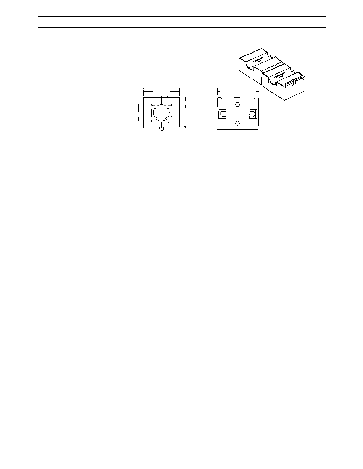
Ferrite Core (Data Line Filter): 0443-164151 (manufactured by Nisshin Electric)
Impedance specifications
25 MHz: 156 Ω
100 MHz: 250 Ω
30 mm
13 mm
29 mm
33 mm
Page 21

xxii
EC Directives 6
Page 22

1
SECTION 1
Available Units and Features
This section describes the features of GRT1-series Slice I/O Units and lists the available Units.
1-1 Slice I/O Terminal Introduction . . . . . . . . . . . . . . . . . . . . . . . . . . . . . . . . . . . 2
1-1-1 Features of the GRT1-series Slice I/O Units . . . . . . . . . . . . . . . . . . 2
1-2 Available Units . . . . . . . . . . . . . . . . . . . . . . . . . . . . . . . . . . . . . . . . . . . . . . . . 7
1-2-1 Communications Units . . . . . . . . . . . . . . . . . . . . . . . . . . . . . . . . . . . 7
1-2-2 Digital I/O Units . . . . . . . . . . . . . . . . . . . . . . . . . . . . . . . . . . . . . . . . 7
1-2-3 Analog I/O Units. . . . . . . . . . . . . . . . . . . . . . . . . . . . . . . . . . . . . . . . 7
1-2-4 Counter Units and Positioning Unit . . . . . . . . . . . . . . . . . . . . . . . . . 8
1-2-5 System Units. . . . . . . . . . . . . . . . . . . . . . . . . . . . . . . . . . . . . . . . . . . 8
1-2-6 Connecting Cable . . . . . . . . . . . . . . . . . . . . . . . . . . . . . . . . . . . . . . . 9
1-2-7 Functions Supported by Slice I/O Units. . . . . . . . . . . . . . . . . . . . . . 9
1-2-8 Slice I/O Unit Installation and Power Supply Methods . . . . . . . . . . 10
Page 23

2
Slice I/O Terminal Introduction Section 1-1
1-1 Slice I/O Terminal Introduction
A Slice I/O Terminal is a building-block style remote I/O terminal made up of a
Communications Unit and a number of Slice I/O Units, which each provide a
small number of I/O points. The Slice I/O Units communicate with the host by
remote I/O communications (cyclic communications) through the Communications Unit. Remote I/O communications (cyclic communications) can be
started just by setting the Communications Unit’s node address and turning
ON the power supply.
Since the Slice I/O Units expand the system in small I/O increments, a flexible
system can be assembled to exactly match various customer applications,
with less labor and space.
1-1-1 Features of the GRT1-series Slice I/O Units
The GRT1-series Slice I/O Units have the following features.
Features Shared by all Units
Small I/O Increments The GRT1-series Slice I/O Units have just a few I/O points (2 to 4 points) per
Unit, so the application can be flexibly constructed to match the space and
capacity requirements.
Building-block Style
Termina ls
Slice I/O Terminals are building-block style Units that can be expanded by
attaching additional Slice I/O Units to the side of the Terminal. Up to 64 Slice I/
O Units can be connected to one Communications Unit.
Time-saving Screwless
Termina l Blocks
Slice I/O Units are equipped with screwless clamp terminal blocks, which can
be wired just by inserting the wire into the terminals. Wires can be removed
just by pressing the release button and pulling out the wire.
Example: DeviceNet
PLC
Serial connection
(For setting, monitoring, and operating)
Slave
GRT1-DRT DeviceNet
Communications Unit
Slice I/O Units
Up to 64 Slice I/O Units can be connected to one DeviceNet Communications Unit.
(Up to 1,024 inputs and outputs can be connected.)
Slice I/O Terminals
DeviceNet Unit
Page 24

3
Slice I/O Terminal Introduction Section 1-1
Parameter Backup and
Restore
Before replacing a Slice I/O Unit for maintenance, the parameter data set in
the I/O Unit can be backed up in the connected Communications Unit. The
backed up parameter data is compared with the replacement I/O Unit’s data
and the backed up data is restored to the replacement I/O Unit.
Online Replacement of I/O
Units
The Slice I/O Units are made up of 3 blocks (the base block, main block, and
terminal block) that can be separated from each other. This means you can
leave the base block connected to the Slice I/O Terminal with power supplied
to the Slice I/O Terminal and replace the main block or terminal block.
Note Turn OFF the I/O power supply before replacing Slice I/O Unit
blocks. Also turn OFF any external power supplied to the terminals.
Automatic Baud Rate
Recognition
It isn’t necessary to set the baud rate on the GRT1-series Slice I/O Units.
Automatic Allocation of
Unit Numbers
Unit numbers are allocated automatically to the connected Slice I/O Units
from left to right and stored within the Communications Unit. It is not necessary for the user to set these numbers.
Remote I/O
Communications
GRT1-series Slice I/O Units communicate with the host Master by remote I/O
communications through the Communications Unit. The Slice I/O Units’ data
is collected in the Communications Unit and exchanged with the Master in a
batch.
Unit Conduction Time
(Power ON Time) Monitor
This function records the total time that the Slice I/O Unit's internal circuit
power has been ON. A warning level can be set in the Unit and a warning flag
will be turned ON when the set warning time is exceeded. The Power ON
Time can be read with an explicit message command or from the Configurator.
Unit Comments A user-set name can be assigned to each Unit and recorded in the Unit.
Connected Device
Comments
User-set names can be assigned to each I/O device (sensor, valve, etc.) connected to a Unit and recorded in the Unit.
Communications Error
History Monitor
The communications error log within the Unit can collect the four most recent
communications errors (communications error cause code and communications power supply voltage when error occurred). The information can be read
with an explicit message command or from the Configurator.
Last Maintenance Date The date on which maintenance was performed can be written in the Unit.
The date can be written from the Configurator.
Digital I/O Unit Features
I/O Power Supply Monitor This function detects whether the I/O power is being supplied and turns ON a
warning flag in the Unit if the I/O power supply is OFF. The flags can be read
with an explicit message command or from the Configurator.
Input Filter The input filter function reads the input value several times during the set
interval and removes irregular data caused by noise and switch chattering.
This function can also be used to create ON/OFF delays.
Sensor Power ON Delay When the I/O power has gone OFF, the sensor power ON delay function
blocks inputs for the first 100 ms after the I/O power is turned back ON. This
function prevents incorrect inputs caused by inrush current at startup after the
I/O power is turned ON.
Page 25

4
Slice I/O Terminal Introduction Section 1-1
Contact Operation
Counter
This function can count the number of times each input or output contact
changes from OFF to ON (maximum resolution: 50 Hz). A warning set value
can be set in the Unit to monitor the number of contact operations, and turn
ON a warning flag in the Status Area when the set value is reached. The Configurator or explicit messages can be used to read the information.
Note The Contact Operation Counter and Total ON Time Monitor cannot be used at
the same time for a single contact.
Total ON Time Monitor This function can record the total ON time of devices connected to the Unit,
such as sensors and relays. The total time is stored in the Unit and can be
read by the Configurator or explicit messages. A warning set value can be set
in the Unit to monitor the total ON time, and turn ON a warning flag in the Status Area when the set value is reached.
Note The Total ON Time Monitor and Contact Operation Counter cannot be used at
the same time for a single contact.
Operation Time Monitor This function can measure and monitor an Input Unit’s operating time. The
time required for a bit to go ON or OFF can be measured at high speed within
the Unit, so that ladder programming is not required to measure the operating
time. The trigger edge (ON
→OFF or OFF→ON), input number, and output
number can be selected freely, providing flexibility when testing. A warning set
value can be set in the Unit to monitor the operating time, and turn ON a
warning flag in the Status Area when the set value is reached.
Analog I/O Unit Features
Setting the Number of AD
Conversion Points
The conversion cycle when both analog input points are used is 2.42 ms max.
The AD conversion cycle can be shortened by reducing the number of points
used (i.e., the number of AD conversion points).
Moving Average Analog Input Terminals can calculate the average of the past eight analog
input values to produce a stable input value even when the input value is
unsteady.
Scaling Scaling allows values to be converted according to the industry unit required
by the user. It reduces the number of operations requiring ladder programming in the Master CPU Unit. Scaling also supports an offset function for compensating for errors in scaled values.
Peak/Bottom Hold The maximum (peak) and minimum (bottom) values input to Analog Input Ter-
minals can be held. These values can then be compared with alarm set values, and flags turned ON accordingly to indicate the status (comparator
function).
Top/Valley Hold (Input
Units Only)
The top and valley values for values input to Analog Input Terminals can be
held. The timing of tops and valleys can be monitored with the Top/Valley
Detection Timing Flags. The top and valley values can be compared with
alarm set values, and flags turned ON accordingly to indicate the status (comparator function).
Rate of Change The rate of change for values input to Analog Input Terminals can be obtained
for each sampling cycle.
Comparator Values input to Analog Input Terminals or values after math processing can be
compared to the alarm set values (HH, H, L, and LL), and the result indicated
with the Analog Status Flags. If the result is outside the set range, the Normal
Flag (pass signal) is turned ON.
Off-wire Detection With Analog Input Terminals, disconnections can be detected in wiring for
analog (voltage or current) inputs that are enabled as AD conversion points.
Page 26

5
Slice I/O Terminal Introduction Section 1-1
The status can be checked at the Master using the Off-wire Detection Flag.
This function is valid only for the input ranges 4 to 20 mA and 1 to 5 V.
User Adjustment Input or output values can be adjusted to compensate for errors in the input or
output voltage or current resulting from the characteristics or connection
methods of the I/O device. Compensation is performed by applying linear conversion based on the points corresponding to 0% and 100%.
Cumulative Counter A cumulated value that approximates the integral of analog input or output val-
ues over time can be calculated and read.
Communications Error
Output (Output Units
Only)
The values output by Output Units when errors occur can be set for each output.
Temperature Input Unit Features
Moving Average Temperature Input Units can calculate the average of the past eight input val-
ues to produce a stable input value even when the input value is unsteady.
Scaling Scaling allows values to be converted according to the industry unit required
by the user. It reduces the number of operations requiring ladder programming in the Master CPU Unit. Scaling also supports an offset function for compensating for errors in scaled values.
Peak/Bottom Hold The maximum (peak) and minimum (bottom) values input to Temperature
Input Units can be held. These values can then be compared with alarm set
values, and flags turned ON accordingly to indicate the status (comparator
function).
Top/Valley Hold The top and valley values for values input to Temperature Input Units can be
held. The timing of tops and valleys can be monitored with the Top/Valley
Detection Timing Flags. The top and valley values can be compared with
alarm set values, and flags turned ON accordingly to indicate the status (comparator function).
Rate of Change The rate of change for values input to Temperature Input Units can be
obtained for each sampling cycle.
Comparator Values input to Temperature Input Units or values after math processing can
be compared to the alarm set values (HH, H, L, and LL), and the result indicated with the Temperature Status Flags. If the result is outside the set range,
the Normal Flag (pass signal) is turned ON.
Off-wire Detection With Temperature Input Units, disconnections can be detected individually for
each sensor input. The status can be checked at the Master using the Offwire Detection Flags.
Input Error Detection
Disable
Detection of input errors, including off-wire detection, can be disabled for
channels that are not used.
User Adjustment Input or output values can be adjusted to compensate for errors in the input or
output voltage or current resulting from the characteristics or connection
methods of the I/O device. Compensation is performed by applying linear conversion based on the points corresponding to 0% and 100%.
Cumulative Counter A cumulated value that gives the integral of analog input values over time can
be calculated and read.
Top or Valley Count The numbers of times that the top or valley value is reached can be counted,
e.g., in an application in which the temperature input value varies in a fixed
cycle of temperature change. The host will be notified with a flag when the
number of cycles exceeds the set value.
Page 27

6
Slice I/O Terminal Introduction Section 1-1
Temperature Zone
Counter
The temperature zone counter can be used to measure how long the temperature input value is within a user-set temperature range in 1-second increments. The host will be notified with a flag when the measured value exceeds
the set value.
Data Comparison between
Channels
The temperature differences between input channels 0 and 1 can be calculated and compared to a set value. The host will be notified with a flag when
the temperature difference exceeds a set value.
Counter Unit and Positioning Unit Features
Counter Each Unit provides one high-speed counter with a 32-bit resolution. Counting
is performed in linear fashion, and encoder signals up to 60 kHz can be input
with Counter Units and up to 100 kHz can be input with Positioning Units. The
Counter Units support 24-V inputs and the Positioning Unit supports either
24-V or line-driver inputs (settable).
Counter Input Modes The counter can be set to any of the following input modes:
• Phase differential
×1
• Phase differential ×2
• Phase differential
×4
• Pulse/direction
•Up/down
Speed Measurement The output pulse frequency is measured and can be read from the I/O area at
any time.
Digital Inputs The Counter Unit supports an input that can be set to operate either as a digi-
tal input or an encoder Z-signal input. The Positioning Unit provides both a
digital input and an encoder Z-signal input.
The digital input can be set to reset the counter, preset the counter, or capture
the present counter value. Any of these actions can be set to be performed on
the rising or falling edge of the digital signal.
The Z-signal input of the Positioning Unit can be set to reset the counter in
various ways.
Digital Outputs Each Counter Unit provides one digital output and the Positioning Unit pro-
vides two digital outputs. A digital output can be used as a general-purpose
output, or it can be controlled using a settable counter value comparison
range.
Comparison Range A comparison range can be enabled for the counter value to control a digital
output. The output will be turned ON or OFF depending on the relationship
between the counter value and the range that is set. Each Counter Unit provides one comparison range.
Page 28
7
Available Units Section 1-2
1-2 Available Units
The following tables list the available GRT1-series Units, categorized by type.
1-2-1 Communications Units
1-2-2 Digital I/O Units
1-2-3 Analog I/O Units
Type I/O points Model number Description
DeviceNet Communications
Unit
--- GRT1-DRT Interface Unit that connects the DeviceNet
Unit with the Slice I/O
Units
PROFIBUS Communications Unit
--- GRT1-PRT Interface Unit that connects the PROFIBUS
Unit with the Slice I/O
Units.
Type I/O points Model number Description
DC Input/Transistor
Output Units
4 inputs (NPN) GRT1-ID4 4 DC inputs
4 inputs (PNP) GRT1-ID4-1
4 outputs (NPN) GRT1-OD4 4 transistor outputs
4 outputs (PNP) GRT1-OD4-1
4 outputs (PNP) GRT1-OD4G-1
4 outputs (PNP) GRT1-OD4G-3 4 transistor outputs (2 A)
8 inputs (NPN) GRT1-ID8 8 DC inputs
8 inputs (PNP) GRT1-ID8-1
8 outputs (NPN) GRT1-OD8 8 transistor outputs
8 outputs (PNP) GRT1-OD8-1
8 outputs (PNP) GRT1-OD8G-1
AC Input Units 4 inputs GRT1-IA4-1 100 to 120 VAC
4 inputs GRT1-IA4-2 200 to 240 VAC
Relay Output Unit 2 outputs GRT1-ROS2 Relay outputs
Type I/O points Model number Description
Analog I/O Units 2 inputs GRT1-AD2 2 analog inputs
2 outputs GRT1-DA2V 2 analog voltage outputs
2 outputs GRT1-DA2C 2 analog current outputs
Temperature Input
Units
2 inputs GRT1-TS2P Resistance thermometer
input
Type:
PT100 (−200 to 850°C)
PT100 (−200 to 200°C)
2 inputs GRT1-TS2PK Resistance thermometer
input
Type:
PT1000 (−200 to 850°C)
PT1000 (−200 to 200°C)
2 inputs GRT1-TS2T Thermocouple input
(R, S, K1, K2, J1, J2, T, E,
B, N, L1, L2, U, W, or PL2;
switchable)
Page 29

8
Available Units Section 1-2
1-2-4 Counter Units and Positioning Unit
1-2-5 System Units
Type I/O Model number Description
Counter
Units
• A and B counter inputs
• One input settable to Z counter
input or digital input
• 1 digital output (NPN)
GRT1-CT1 1 counter
Max. frequency:
60 kHz (depending on counter
input mode)
• A and B counter inputs
• One input settable to Z counter
input or digital input
• 1 digital output (PNP)
GRT1-CT1-1
Positioning
Unit
• A, B, and Z counter inputs
• 1 digital input
• 2 digital outputs (PNP)
GRT1-CP1-L 1 counter
Max. frequency:
100 kHz (depending on interface
and counter input
mode)
Type I/O points Model number Description
Right Turnback Unit --- GRT1-TBR Mounts to the right side of
the last Unit to add a new
block.
Left Turnback Unit --- GRT1-TBL Mounts to the left side of
the new block. Power is
supplied from the Left
Tur nb a ck Un i t.
I/O Power Feed Units --- GRT1-PD2 Feeds I/O power within the
Slice I/O Terminal.
2 voltage terminals and
2 ground terminals
--- GRT1-PD2G Feeds I/O power within the
Slice I/O Terminal.
2 voltage terminals and
2 ground terminals
Overcurrent protection
--- GRT1-PD8 Feeds I/O power within the
Slice I/O Terminal.
8 voltage terminals and
4 ground terminals
--- GRT1-PD8-1 Feeds I/O power within the
Slice I/O Terminal.
4 voltage terminals and
8 ground terminals
I/O Power Connection
Units
--- GRT1-PC8 Provides extra voltage and
ground terminals.
8 voltage terminals and
4 ground terminals
--- GRT1-PC8-1 Provides extra voltage and
ground terminals.
4 voltage terminals and
8 ground terminals
End Unit --- GRT1-END An End Unit must be
mounted to the end of the
Slice I/O Terminal.
Page 30
9
Available Units Section 1-2
1-2-6 Connecting Cable
1-2-7 Functions Supported by Slice I/O Units
Type I/O points Model number Description
Turnback Cable for
Slice I/O Units (1 m)
--- GCN2-100 This is a special turnback cable.
Up to 2 Turnback Cables (2 m
total) can be connected for one
Communications Unit.
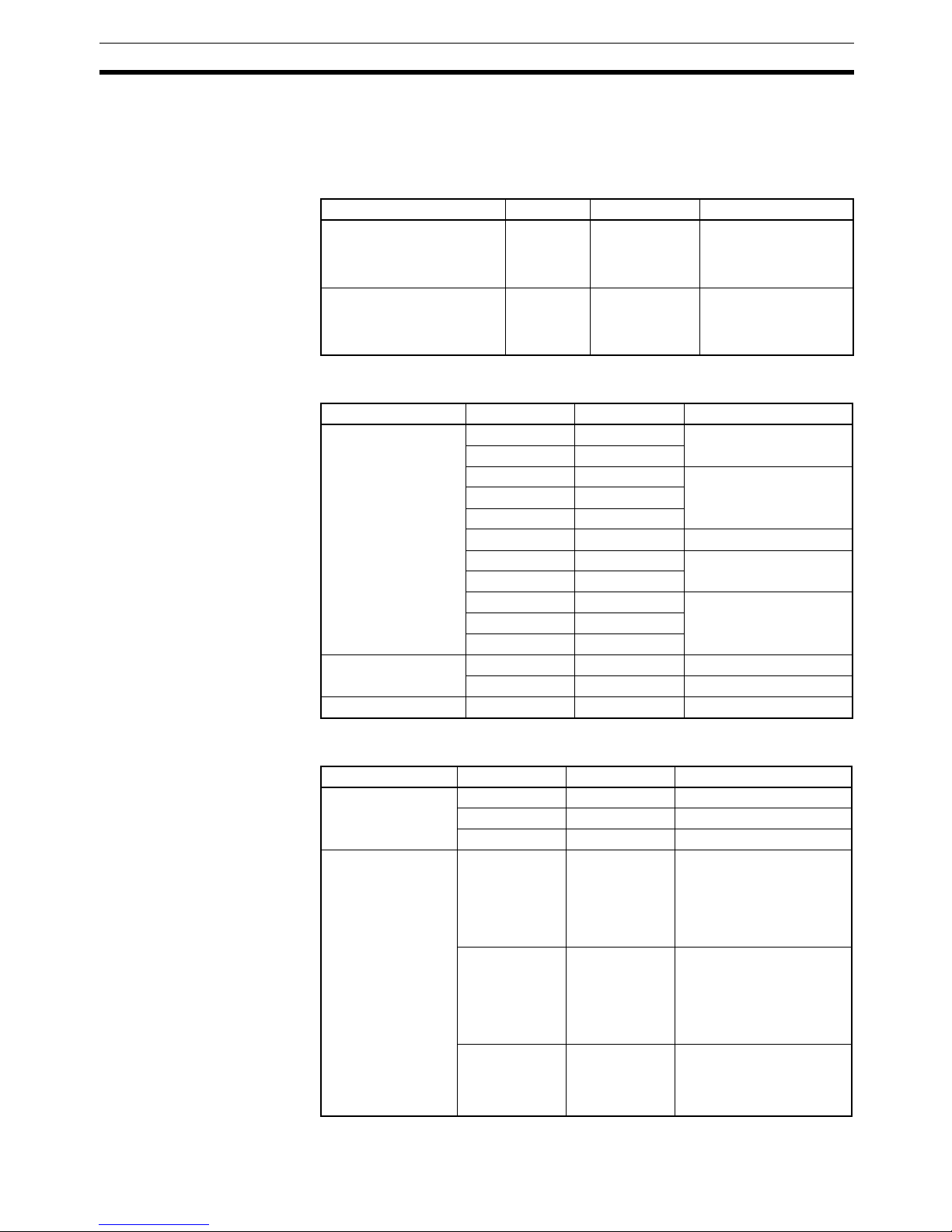
Function GRT1-series Slice I/O Units
Digital I/O Units Analog I/O Units Tempera-
ture Input
Units
Counter
Units and
Position-
ing Unit
DC Input
Units
AC Input
Units
Output
Units
Relay
Output
Units
Input
Units
Output
Units
Backup/Restore Supported
Online Replacement Supported
Automatic Baud Rate
Recognition
Supported
Unit Conduction Time
(Power ON Time) Monitor
Supported
Unit Comments Supported
Connected Device Com-
ments
Supported
Last Maintenance Date Supported
Communications Error
History Monitor
Supported
Detachable Terminal
Block
Supported
Total ON Time Monitor Supported --- Supported
Contact Operation
Counter
Supported --- Supported
Operation Time Monitor Supported --I/O Power Supply Monitor Supported --- Supported --- Supported
Input Filter Supported --Sensor Power ON Delay Supported --Scaling --- Supported --User Adjustment --- Supported --Cumulative Counter --- Supported --Moving Average --- Supported --- Supported --Setting the Number of AD
Conversion Points
--- Supported --- --- ---
Input Error Detection Disable
--- --- --- Supported ---
Peak/Bottom Hold --- Supported --- Supported --Top/Valley Hold --- Supported --- Supported --Rate of Change --- Supported --- Supported --Comparator --- Supported --- Supported --Communications Error
Output
--- Supported --- Supported --- Supported
Temperature Zone
Counter
--- --- --- Supported ---
Data Comparison
between Channels
--- --- --- Supported ---
Page 31

10
Available Units Section 1-2
1-2-8 Slice I/O Unit Installation and Power Supply Methods
The following installation and power supply methods apply to all GRT1-series
Units.
I/O Unit connection Unit
installation
I/O connection Unit power supply to
base block
I/O power supply
Building-block connections
with slide connectors on
sides of Units
DIN Track installation
Screwless clamping terminal block
Supplied through the
Communications Unit or
Left Turnback Unit.
Supplied through the
Communications Unit, I/O
Power Feed Unit, or Left
Tur nba ck Un i t.
Page 32

11
SECTION 2
Shared Specifications and Functions
This section describes the specifications and functions that are shared by all of the Slice I/O Units.
2-1 Specifications Shared by the Units . . . . . . . . . . . . . . . . . . . . . . . . . . . . . . . . . 12
2-1-1 General Specifications . . . . . . . . . . . . . . . . . . . . . . . . . . . . . . . . . . . 12
2-1-2 Slice I/O Unit Specifications . . . . . . . . . . . . . . . . . . . . . . . . . . . . . . 12
2-1-3 LED Indicators . . . . . . . . . . . . . . . . . . . . . . . . . . . . . . . . . . . . . . . . . 12
2-2 Unit Numbers and I/O Allocations . . . . . . . . . . . . . . . . . . . . . . . . . . . . . . . . . 13
2-2-1 Unit Numbers of Slice I/O Units (Automatically Allocated) . . . . . . 13
2-2-2 I/O Allocations in the Slice I/O Terminal’s Master Unit . . . . . . . . . 14
2-3 Functions Shared by all Units . . . . . . . . . . . . . . . . . . . . . . . . . . . . . . . . . . . . . 17
2-3-1 Backup Function. . . . . . . . . . . . . . . . . . . . . . . . . . . . . . . . . . . . . . . . 17
2-3-2 Automatic Restore Function. . . . . . . . . . . . . . . . . . . . . . . . . . . . . . . 18
2-3-3 Online Replacement Function . . . . . . . . . . . . . . . . . . . . . . . . . . . . . 19
2-3-4 Unit Conduction Time Monitor . . . . . . . . . . . . . . . . . . . . . . . . . . . . 20
2-3-5 Unit Comments. . . . . . . . . . . . . . . . . . . . . . . . . . . . . . . . . . . . . . . . . 22
2-3-6 I/O Comments. . . . . . . . . . . . . . . . . . . . . . . . . . . . . . . . . . . . . . . . . . 23
2-3-7 Communications Error History Monitor . . . . . . . . . . . . . . . . . . . . . 26
2-3-8 Last Maintenance Date . . . . . . . . . . . . . . . . . . . . . . . . . . . . . . . . . . . 28
Page 33

12
Specifications Shared by the Units Section 2-1
2-1 Specifications Shared by the Units
2-1-1 General Specifications
2-1-2 Slice I/O Unit Specifications
2-1-3 LED Indicators
The following table shows the meaning of the Unit’s TS and I/O indicators,
which are common to all of the Slice I/O Units.
The ERR indicators show errors specific to the Unit, such as I/O errors. Any
numbers that immediately follow “ERR” indicate the channel number, e.g.
ERR0 indicates a Unit that has an error in channel 0.
Item Specification
Ambient operating temperature
−10 to 55
°C (with no icing or condensation)
Ambient operating humidity 25% to 85%
Ambient storage temperature
−25 to 65°C (with no icing or condensation)
Noise immunity Conforms to IEC61000-4-4, 2.0 kV
Vibration resistance 10 to 60 Hz: 0.7 mm double amplitude
60 to 150 Hz: 50 m/s
2
Shock resistance
150 m/s
2
Withstand voltage 500 VAC (between isolated circuits)
Enclosure rating IP20
Item Specification
Communications protocol Slice bus
Communications distance Slice I/O Units: 64 Units coupled (about 2 m max.)
Turnback Cable: 2 m max. (2 cables, 1 m each)
Unit power supply Voltage: 24 VDC
Unit connection method Building-block style configuration with slide connec-
tors on sides of Units
Unit number 1 to 64 (automatically allocated)
I/O power supply Voltage: 24 VDC
Current: 4 A max.
Indicators TS
(Two-color LED)
Indicates the Unit’s operating status
IO
(One-color LED)
Indicates the I/O status
Page 34

13
Unit Numbers and I/O Allocations Section 2-2
The TS indicator shows the status of the Slice I/O Unit itself and the I/O indicators show the status of the connected devices.
■ Digital I/O Units
The following table shows the meaning of the yellow I/O indicator.
The following table shows the meaning of the red ERR indicator.
2-2 Unit Numbers and I/O Allocations
2-2-1 Unit Numbers of Slice I/O Units (Automatically Allocated)
The numbers used to identify the Slice I/O Units in a Slice I/O Terminal are
called the Slice I/O Units’ unit numbers. These unit numbers are allocated
automatically from left to right starting from #1, when the power is turned ON.
It is not necessary for the user to set these numbers.
Name Color Status Meaning
TS Green Lit Normal status Normal Unit status
Normal network status
Flashing Operating The automatic restore/backup
function is operating.
Red Lit Fatal error Unit hardware error
(EEPROM error or WDT
error)
Flashing Non-fatal error Communications timeout,
incorrect switch setting, etc.
Cold junction compensator
error (GRT1-TS2T only)
--- Not lit No power • Unit power supply is OFF.
• Unit is waiting for initialization.
• Unit is being reset.
TS
TS
TS
TS
TS
Name Color Status Meaning
I/O Yellow Lit Normal status I/O ON
--- Not lit --- I/O OFF
Name Color Status Meaning
ERR Red Lit Error The error depends on the
Unit. Refer to specific information for the relative Unit.
--- Not lit Normal status No error has occurred.
Page 35

14
Unit Numbers and I/O Allocations Section 2-2
Note The unit numbers allocated automatically to the Slice I/O Units are unrelated
to the DeviceNet node address set with the rotary switches.
2-2-2 I/O Allocations in the Slice I/O Terminal’s Master Unit
The Slice I/O Terminal’s I/O data is allocated in the CPU Unit’s I/O memory
and transferred through the Communications Unit and the Unit (such as a
DeviceNet Unit) connected to the CPU Unit.
The Communications Unit’s Programming Device (such as a Configurator)
can be used to freely select the kind of data allocated. Refer to the Communications Unit’s operation manual for details.
Communications Unit
The Slice I/O Units' unit numbers are allocated
automatically in order, from left to right.
I/O
#1
I/O
#2
I/O #3I/O
#4
I/O
#64
:
:
E
Connected order
CPU Unit
Master Unit
I/O memory
A
B
CD
E
Communications
Unit
A
BC
D
Slice I/O Terminal
Data is allocated to I/O memory in the order
that the Units are connected, from lowest to
highest.
I/O Units with bit allocation are allocated data
from the rightmost to leftmost bit, in 2-bit units.
I/O Units with word allocations are allocated
data from the lower to higher word address.
0
8
16
Order of allocation
(1) Communications Unit status
(2) Each Slice I/O Unit's I/O data.
(3) Slice I/O Unit network
participation status.
Page 36

15
Unit Numbers and I/O Allocations Section 2-2
I/O Allocation
Example
I/O data is allocated to the I/O Units in the order that they are connected to the
Communications Unit, regardless of the I/O Units’ models. Unless special
allocation data settings are selected with the Communications Unit’s Programming Device, data is allocated from the first word starting with the Communications Unit’s Status Flags and then the leftmost I/O Unit’s data.
Data in the Master’s Input and Output Areas is allocated to the Slice I/O Units
based on their unit numbers.
Note I/O Units with bit allocations (such as the GRT1-ID4/OD4) are allocated data
in 2-bit units. I/O Units with word allocations (such as the GRT1-AD2) are allocated data in 1-word units. The following example shows the allocations to
Output Units.
#1
ID4#2ID4#3ID4#4AD2
#6
OD4#7ROS2#8OD8#9OD4
#5
ID8
First Word
+1
+2
+3
Communications Unit Status
Unused
#3 #2 #1
#4
+4 #5
First Word
+1
+2
Unused
#7 #6
Unused
Unused
#9
Some areas may be unused when data is allocated.
Word
Input Area
08
15
015 8
Output Area
Unused
#8
Communications
Unit
Data is allocated in 2-bit units
to I/O Units that require 4 bits,
so there may be unused areas
as shown in the following table.
Slice I/O Terminal Configuration
#1
OD4
#2
OD4
#3
OD4
#4
ROS2
#6
DA2
#5
OD4
#8
OD8
#7
OD4
+0
+1
+2
+3
#
5
#3 #2 #1
#6
+4
Word
8
15
0
Unused
#
5
#
4
Unused
#7
+5
Unused #8
Communications
Unit
Data in these areas will not be output.
Page 37

16
Unit Numbers and I/O Allocations Section 2-2
Note As shown in example 1, 0 is entered into any unused area that creates a gap
in another area. Such an area cannot be used for any other purpose. If there
is more than 1 byte that do not create a gap in any other area, such as in word
4 in example 2, then they can be used for other purposes.
Allocated Data
Patterns
The following kinds of data can be allocated for the Master. The Programming
Device can be used to freely select the kinds/combination of data allocated. If
the Programming Device isn’t used to select the data pattern, the default setting is used, which is I/O data + Communications Unit Status Flags (pattern
number 1 in the following table).
#2
AD2
#3
ID4
#4
ID4
#5
ID4
#1
ID4
+2
+3
+1
CH
15 8 0
#1
+4
0
#2
+0
#3 #4 #5
#2
AD2
#3
ID4
#4
ID4
#5
ID4
#1
ID4
+2
+3
+1
15 8 0
#1
+4
0
#2
+0
#3 #4 #5
Communications Unit Status
Communications
Unit
0
Word
A 0 will be entered into the unused areas.
These areas cannot be used for any other
purposes.
Example Input Area 1 (Total of 10 Bytes)
#2
AD2
#3
ID4
#4
ID4
#1
ID4
+2
+3
+1
15 8 0
#1
+4
0
#2
+0
#3 #4
Communications Unit Status
Communications
Unit
Word
Unused
Nothing will be input into this unused area.
If there is more then one unused byte that does
not create gaps in any area, then it can be used
for another purpose.
A 0 will be entered into this unused area.
This area cannot be used for other purposes.
Example Input Area 2 (Total of 9 Bytes)
Page 38

17
Functions Shared by all Units Section 2-3
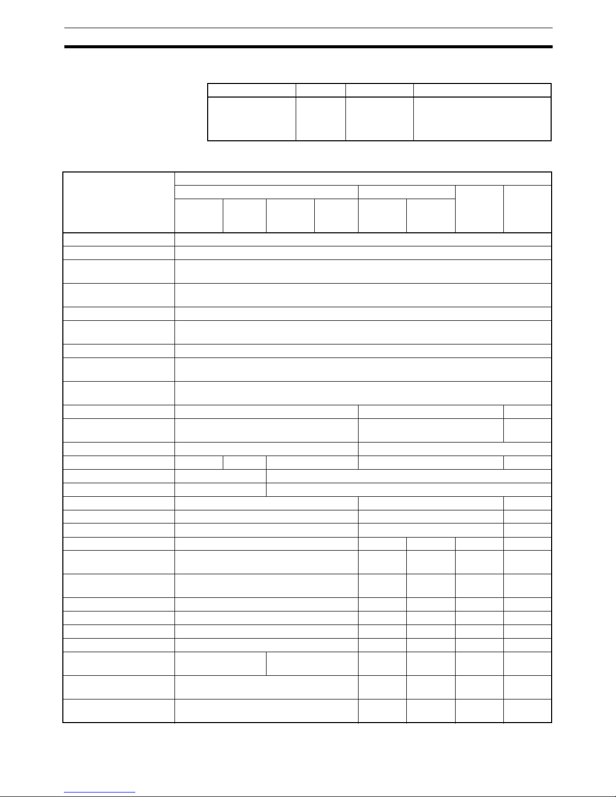
Input Data Patterns and Sizes
Output Data Patterns and
Sizes
(1) Only one pattern of output data can be allocated.
(2) When allocating data, be sure that it does not exceed the maximum that
can be allocated (64 words).
2-3 Functions Shared by all Units
2-3-1 Backup Function
Function Overview The backup function records the parameter data of all Slice I/O Units con-
nected to the Communications Unit. The parameter data recorded in the
Communications Unit can be restored to the Slice I/O Units later with the
automatic restore function when a Slice I/O Unit has been replaced.
Backup Procedure when
using a DeviceNet
Communications Unit
1,2,3... 1. Verify that the power is ON, DIP switch pin 1 (REGS) is ON, and all of the
Slice I/O Units are participating in I/O communications.
Allocated data pattern Description
1. Input data + Communications
Unit Status Flags
Used input data size + 1 word
Maximum Input Area: 65 words (with Communica-
tions Unit)
2. Input data only The total of the bit, word, and used areas. Calcu-
late following the previous example.
Maximum Input Area: 64 words (with Communica-
tions Unit)
3. Communications Unit Status
Flags only
1 word (with Communications Unit)
4. Slice I/O Unit Communications Participating/Withdrawn
Flags only
Participating Flags: 4 words
Withdrawn Flags: 4 words
Total: 8 words
Allocated data pattern Description
Output data only The total of the bit, word, and used areas. Calcu-
late following the previous example.
Maximum Input Area: 64 words (with Communica-
tions Unit)
Communications
Unit
Turn pin 4 ON, OFF, and
then ON again while the
power is ON and pin 1 is ON.
Downloads all of the I/O Units' unit
information and
p
arameter data.
#1
#2 #3 #4
Power ON
Page 39

18
Functions Shared by all Units Section 2-3
2. Turn DIP switch pin 4 (BACK) ON, then OFF, and then ON again within 3 s
to start the back up.
3. While the data is being backed up, the DeviceNet Communications Unit’s
TS indicator will flash green every 0.5 s. The TS indicator will stop flashing
(not lit) when the backup is completed.
If the restore operation fails, the TS indicator will be lit red for 2 s.
Note (1) Do not turn OFF the power supply or reset the Configurator while data is
being backed up. The data will not be backed up properly if the power is
turned OFF.
(2) The backup data will be erased along with the registered I/O configuration
table if the power is turned OFF and back ON or if the Unit is restarted
while DIP switch pin 1 (REGS) is turned OFF.
(3) We recommend backing up the parameter data in case a Unit fails in the
future.
2-3-2 Automatic Restore Function
Function Overview When a Slice I/O Unit has been replaced, this function will automatically
download (restore) Slice I/O Unit parameter data that was previously backed
up in the Communications Unit. The following conditions are required to execute the automatic restore function:
• DIP switch pin 1 (REGS) was ON when the power was turned ON, so the
registered table is enabled.
• DIP switch pin 3 (ADR) was ON when the power was turned ON, so the
automatic restore function is enabled.
• Parameter data has been backed up.
Restoration Procedure
when using a DeviceNet
Communications Unit
1,2,3... 1. Create backup data in the Communications Unit with the backup function.
2. Turn ON DIP switch pin 3 (ADR).
Unit Replacement
Procedure
1,2,3... 1. Turn OFF the Slice I/O Terminal’s power supply and the I/O power supply.
2. Release the hook on the front of the I/O Unit that you want to replace and
remove the terminal block. The wiring can remain connected.
3. Remove the main block of the Slice I/O Unit and replace it with a new I/O
Unit.
4. Mount the terminal block that was removed in step 2 and latch the hook
that was released.
Communications
Unit
Pin 1 was ON when power
is turned ON and pin 3 is
turned from OFF to ON.
Parameter data is automatically restored only
to the Unit that was replaced (same unit number,
same model number, different serial number).
Parameter data
Power ON
#1
#2 #3 #4
Page 40

19
Functions Shared by all Units Section 2-3
5. When the power is turned ON again, the Communications Unit will automatically detect the Unit that was replaced and download the backup data.
The I/O Unit’s TS indicator will indicate the results of the restore operation.
• If the download was successful, the Unit will be reset automatically and
join I/O communications normally. The I/O Unit’s TS indicator will be lit
green.
• If the download failed, the I/O Unit’s TS indicator will be flash red.
• If the connected Unit is the wrong model, the I/O Unit’s TS indicator will be
lit red.
Note (1) Do not turn OFF the power or reset the Unit from the Configurator while
data is being restored. The data will not be restored properly if the power
is turned OFF or the Unit is reset.
(2) When an I/O Unit has been replaced with the power ON and the new I/O
Unit joins I/O communications, the new Unit will be compared to the previous one and the parameter data restore operation will start automatically. While data is being restored, the DeviceNet Communications Unit’s TS
indicator will flash green every 0.5 s. The TS indicator will stop flashing
(not lit) when the restore operation is completed. If the restore operation
fails, the Automatic Restore Monitor Flag (bit 13 of the Communications
Unit Status Flags) will be turned ON and the Communications Unit’s TS
indicator will be lit red for 2 s.
2-3-3 Online Replacement Function
Function Overview When one of the Slice I/O Units connected to the Communications Unit must
be replaced, the Unit can be replaced without turning OFF the Slice Bus
Power. Any AC power supplied via the Slice I/O Terminal must always be
turned OFF before replacing a Unit.
The Units can be replaced online because the Slice I/O Units are made up of
3 blocks: the base block, main block, and terminal block. When replacing a
Slice I/O Unit, leave just the base block connected and replace the main
block. I/O communications will continue with the other I/O Units even while the
problem Unit is being removed and replaced.
Replacement Procedure
1,2,3... 1. Turn OFF the I/O power supply of the I/O Unit being replaced.
2. Release the hook on the front of the I/O Unit that you want to replace and
remove the terminal block. The wiring can remain connected.
3. Remove the main block of the Slice I/O Unit and replace it with a new I/O
Unit.
To keep the system online, leave the
communications block connected.
Unit being
replaced
If pin 1 and pin 3 are ON,
data is automatically restored
to the replaced Unit.
Power ON
Communications
Unit
#1
#2
#3
#4
Page 41

20
Functions Shared by all Units Section 2-3
4. Mount the terminal block that was removed in step 2 and latch the hook
that was released.
5. Turn ON the I/O power supply.
!WARNING Always turn OFF the I/O Unit's I/O power supply before performing online
replacement. In addition, if external power is supplied to the terminal block for
a Unit such as a Relay Output Unit or AC Input Unit, turn OFF that power supply before replacing the Unit. Not turning OFF these power supplies may
result in false output signals, false input signals, or electrical shock.
Note (1) When a Unit withdraws from I/O communications during replacement, the
corresponding Slice I/O Unit Communications Withdrawn Flag will go ON
and the Communications Unit’s TS indicator will flash red.
(2) Before using the automatic restore function, the preparation for automatic
restoration (creating backup data and turning ON DIP switch pin 3) must
be completed. Refer to 2-3-2 Automatic Restore Function for details.
(3) Only replace one I/O Unit at a time.
(4) Always replace the I/O Unit with the same model of I/O Unit. If a Unit is
replaced with a different model, there may be unexpected outputs and the
restore operation may not be completed properly.
(5) If the base block is faulty or damaged, turn OFF the power supply and re-
place the entire Unit. Even in this case, the I/O Unit’s parameter data will
be restored automatically if the automatic restore function is enabled
when the power is turned ON.
2-3-4 Unit Conduction Time Monitor
Function Overview The total ON time (unit: 0.1 hr) of the Unit's internal circuit power can be cal-
culated and recorded.
A monitor value can be set in the Unit so that the corresponding notification
flag in the Status Area will be turned ON when the total time reaches the set
monitor value in order to notify the Communications Unit. (Bit 2 of the Communication’s Unit’s Status Flags will go ON.) The total ON time can be read
with a Programming Device.
• Measured time: 0 to 429496729 hours (stored data: 00000000 to
FFFFFFFF hex)
Page 42

21
Functions Shared by all Units Section 2-3
• Measuring unit: 0.1 hr
Note The Unit conduction time monitor (Power ON time monitor) calculates the total
time that Network power supply is ON. The total time is not calculated when
the power is OFF.
Setting with a
Programming Device
This example shows how to use the DeviceNet Configurator (version 2.43 or
higher) to set the monitor value for the Unit Conduction Time.
1,2,3... 1. Open the Network Configuration Window and double-click the desired
Slice I/O Terminal’s icon or right-click the icon and select Parameters -
Edit to display the Edit Device Parameters Window.
2. Click the I/O Module Ta b.
Host Master
Total ON time
Internal circuit
power
ON
OFF
Communications
Unit
Recorded in Unit
Corresponding bit
turned ON when
monitor value is
exceeded.
Corresponding bit is turned
ON in the Communications
Unit's status flags.
Slice I/O Unit
Page 43

22
Functions Shared by all Units Section 2-3
3. Click the Edit Button to display the Edit Unit Parameters Window.
4. Input the desired monitor value in the Unit Conduction Time Field.
5. Click the Download Button, and then click the Reset Button to reset the
Unit.
6. Click the OK Button.
2-3-5 Unit Comments
Function Overview The user can assign and record a name or comment for every Unit (up to 32
characters). The network Programming Device can be used to read and write
these Unit names (comments).
Setting with a
Programming Device
This example shows how to use the DeviceNet Configurator (version 2.43 or
higher) to set the Unit Comments.
1,2,3... 1. Open the Network Configuration Window and double-click the desired
Slice I/O Terminal’s icon or right-click the icon and select Parameters -
Edit to display the Edit Device Parameters Window.
Slice I/O Unit
Recorded in Unit
Unit comment
Set a Unit name with th
e
Programming Device.
Page 44

23
Functions Shared by all Units Section 2-3
2. Click the I/O Module Ta b.
3. Click the Edit Button to display the Edit Unit Parameters Window.
4. Input the desired name in the Comment Field.
5. Click the Download Button, and then click the Reset Button to reset the
Unit.
6. Click the OK Button.
2-3-6 I/O Comments
Function Overview The user can assign a name for each of the Unit's I/O contacts (up to 32 char-
acters) and record it in the Unit. The connected device can be checked for
each I/O contact, allowing faulty devices to be identified during remote maintenance. The network Programming Device can be used to read and write the
names (comments) of the connected devices.
Page 45

24
Functions Shared by all Units Section 2-3
Slice I/O Unit
Recorded in Unit
Connected
device
Connected device
comment
What is this connected
device used for?
Set a device comment with
the Programming Device.
Page 46

25
Functions Shared by all Units Section 2-3
Setting with a
Programming Device
This example shows how to use the DeviceNet Configurator (version 2.43 or
higher) to set the device comments.
1,2,3... 1. Open the Network Configuration Window and double-click the desired
Slice I/O Terminal’s icon or right-click the icon and select Parameters -
Edit to display the Edit Device Parameters Window.
2. Select the desired Slice I/O Unit from the list on the I/O Module Tab Page
and click the Edit Button.
3. Select the IN Tab or OUT Tab. (In this case, the IN Tab has been selected.)
4. Select the connected device that requires a comment and double-click the
I/O Comment Column to display the following window. Input the desired
name and click the OK Button.
5. Click the General Ta b.
6. Click the Download Button, and then click the Reset Button to reset the
Unit.
7. Click the OK Button.
Page 47

26
Functions Shared by all Units Section 2-3
2-3-7 Communications Error History Monitor
Function Overview Information on communications error (communications error code, communi-
cations power voltage when the error occurred) for the last four communications errors can be recorded in the Unit. The network Programming Device
can be used to read that communications error history.
Reading with a
Programming Device
This example shows how to use the DeviceNet Configurator (version 2.43 or
higher) to check the error information.
1. Open the Network Configuration Window, right-click the desired Slice I/O
Terminal’s icon, and select Maintenance Information from the pop-up
menu.
What happened to cause
a communications error?
Status when communications
error occurred.
First error
Second error
Third error
Fourth error
Slice I/O Unit
The last 4 errors are
recorded in the Unit.
Page 48

27
Functions Shared by all Units Section 2-3
2. Select the desired Slice I/O Unit from the list on the I/O Module Tab Page
and click the View Button.
3. Select the Error History Tab in the Maintenance Information Window.
The communications error history for the last four errors will be displayed,
as shown in the following window.
Page 49

28
Functions Shared by all Units Section 2-3
2-3-8 Last Maintenance Date
Function Overview This function can be used to write the date on which maintenance was last
performed to the Unit. This means that the timing for future maintenance can
be judged more easily. The date can be written using the network Programming Device.
Setting with a
Programming Device
This example shows how to use the DeviceNet Configurator (version 2.43 or
higher) to check the last maintenance date.
1,2,3... 1. Open the Network Configuration Window and double-click the desired
Slice I/O Terminal’s icon or right-click the icon and select Parameters -
Edit to display the Edit Device Parameters Window.
2. Select the desired Slice I/O Unit from the list on the I/O Module Tab Page
and click the Edit Button.
3. Click the General Tab and select the desired date from the pull-down menu
in the Last Maintenance Date Field. (Click the Today Button to enter the
current date.)
4. Click the Download Button, and then click the Reset Button to reset the
Unit.
5. Click the OK Button.
Page 50

29
SECTION 3
Installation and Wiring
This section provides information on installing and wiring the Slice I/O Units.
3-1 Installation. . . . . . . . . . . . . . . . . . . . . . . . . . . . . . . . . . . . . . . . . . . . . . . . . . . . 30
3-1-1 Connecting the Communications Unit and Slice I/O Units . . . . . . . 30
3-1-2 Connecting Additional Slice I/O Units. . . . . . . . . . . . . . . . . . . . . . . 31
3-1-3 Installation on a DIN Track . . . . . . . . . . . . . . . . . . . . . . . . . . . . . . . 32
3-2 Power Supply Wiring . . . . . . . . . . . . . . . . . . . . . . . . . . . . . . . . . . . . . . . . . . . 36
3-2-1 Connecting the Slice I/O Terminal Power Supply . . . . . . . . . . . . . . 37
3-2-2 Wiring Methods . . . . . . . . . . . . . . . . . . . . . . . . . . . . . . . . . . . . . . . . 39
3-3 Connecting Turnback Cables . . . . . . . . . . . . . . . . . . . . . . . . . . . . . . . . . . . . . 40
3-3-1 Connecting Turnback Units . . . . . . . . . . . . . . . . . . . . . . . . . . . . . . . 41
Page 51

30
Installation Section 3-1
3-1 Installation
The Slice I/O Terminal is installed and set up as a network Slave. The Communications Unit’s communications connector connects to the Master Unit
through a communications cable.
Up to 64 Slice I/O Units can be connected to one Communications Unit.
Note (1) Do not connect or disconnect the Communications Unit’s communica-
tions cable while the network is operating. Short-circuits or poor contacts
in the cable may prevent normal communications.
(2) Be sure that the power supplies for the Communications Unit, Slice I/O
Units connected to the Communications Unit, and external I/O are wired
correctly through the Communications Unit’s terminal block.
3-1-1 Connecting the Communications Unit and Slice I/O Units
Connect the first Slice I/O Unit to the Communications Unit by aligning the
sides of the Units and sliding in the Slice I/O Unit from the front. Additional
Slice I/O Units can be connected consecutively to the first.
In the following example, a Slice I/O Unit is being connected to a DeviceNet
Communications Unit.
Note Do not touch the connector on the Unit’s base block.
Master
Communications Unit
Slide Slice I/O Units in from
the front to install.
Slice I/O Units (64 max.)
24 VDC
for Unit
24 VDC
for I/O
Slide the Slice I/O Unit toward the DIN Track from
the front. Insert the Unit until you hear a click,
which indicates that the Unit has locked on the Track.
It is not normally necessary to release the DIN Track
mountin
g
hook when mounting the Unit.
Page 52

31
Installation Section 3-1
3-1-2 Connecting Additional Slice I/O Units
Connect additional Slice I/O Units by aligning the sides of the Units and sliding in the next Unit from the front. Up to 64 Slice I/O Units can be connected
to one Communications Unit.
Connecting Turnback
Units
When a Slice I/O Terminal is divided into blocks, connect a GRT1-TBR Right
Turnback Unit to the right end of the first block. Connect a GRT1-TBL Left
Turnback Unit to the left side of the expansion block and connect additional
Slice I/O Units. Use a GCN2-100 Turnback Cable to connect the Turnback
Units together.
Note The Turnback Units can be used to divide a Slice I/O Terminal into up to three
blocks.
Slide the Unit to the DIN Track from the front.
Insert the Unit until you hear a click, which indicates
that the Unit has locked on the Track.
It is not normally necessary to release the DIN Track
mounting hook when mounting the Unit.
GRT1-TBR Turnback Unit
(for ri
g
ht side of block)
Turnback Cable connectors
GRT1-TBL Turnback Unit
(for left side of block)
Page 53

32
Installation Section 3-1
Connecting the End
Unit
A GRT1-END End Unit must be connected to the end of the Slice I/O Terminal.
Note When connecting Units, always align the guide tracks on the top and bottom
of the Units and be sure that they join properly as you slide the Unit toward the
DIN Track.
3-1-3 Installation on a DIN Track
DIN Track Installation Mount the Communications Unit and Slice I/O Units on a DIN Track. Attach
the DIN Track with screws in every fourth mounting hole.
PFP-50N (50 cm) or PFP100N (100 cm) DIN Track
PFP-M End Plate (Two
Required)
GRT1-END End Unit
Attach the track with screws at a
maximum spacing of 105 mm
between ad
j
acent screws.
Page 54

33
Installation Section 3-1
Slice I/O Terminal
Orientation
There is no particular restriction on the Slice I/O Terminal’s orientation. The
Terminal can be mounted in any of the following 6 directions.
Installing a Unit Press the Units onto the DIN Track firmly from the front. Press the Unit firmly
until it clicks, indicating that the Unit’s DIN Track Mounting Hooks have locked
onto the DIN Track.
Note It is not normally necessary to release the DIN Track mounting hook when
mounting the Unit. When the Units are installed on a DIN Track other than the
recommended track, the Mounting Hooks may not lock onto the track completely. In that case, release the Mounting Hook locks, mount the Unit on the
DIN Track again, and lock the Mounting Hooks.
Slice I/O Unit
Structure
The Slice I/O Units are made up of 3 blocks. Each block can be removed for
replacement.
Press firmly towards the DIN Track.
Press firmly until you hear a click,
indicating that the Mounting Hooks
have locked.
Mounting Hooks
When the Unit is pushed onto the DIN Track,
verify that the Mounting Hooks have locked.
Page 55

34
Installation Section 3-1
Removing a Unit Use a standard screwdriver to release the DIN Track Mounting Hooks at the
top and bottom of the Unit and pull the Unit straight away from the DIN Track.
Main Block
Base Block
Terminal Block
This is the terminal block of the Slice I/O Unit.
If the main block is damaged or needs to be
replaced for any other reason, the wiring
connected to the terminal block does not
need to be removed.
This is the bus section of the Slice I/O Unit.
If the main block is damaged or needs to be
replaced for any other reason, the base block
can be left connected to the Slice I/O Terminal
so that the main block can be replaced online.
Page 56

35
Installation Section 3-1
Removing an Entire Unit
Including the Base Block
1,2,3... 1. Remove the main block of the Unit on the right side of the Slice I/O Unit
actually being replaced.
2. Release the Mounting Hook locks of the Unit being replaced. (The hooks
attach the Unit to the top and bottom of the DIN Track.)
3. Pull the Unit straight away from the DIN Track.
Removing Just a Unit’s
Main Block
Press the latches on the top and bottom of the main block and pull the block
forward.
Removing Only the
Termina l Block
Release the hooks on the top and bottom of the terminal block and pull out the
terminal block.
B
B
A
C
Unit being replaced
Press the latches on the top and bottom o
f
the main block and pull the block forward.
Release the hooks on the top
and bottom of the terminal block.
Page 57

36
Power Supply Wiring Section 3-2
Installing the End
Plates
Always secure the Slice I/O Terminal on the DIN Track by installing End Plates
on both sides of the Terminal. First hook the bottom of the End Plate on the
bottom edge of the DIN Track (1), attach the top of the End Plate, and pull the
End Plate down onto the top edge of the DIN Track (2).
Tighten the End Plate’s securing screw.
Note Always secure the Slice I/O Terminal by attaching End Plates on both ends.
3-2 Power Supply Wiring
Both the Slice I/O Terminal power supply and the external I/O power supply
are connected with screwless clamp terminals on the Communications Unit.
The following I/O Power Feed Units and I/O Power Connection Units are available. Select the Unit depending on the application. For information on wiring
for the GRT1-PD8(-1) and GRT1-PC8(-1), refer to the wiring examples for the
GRT1-ID8(-1) and GRT1-OD8(-1) in SECTION 4 Digital I/O Units.
1
2
End Unit
End Plate
End Plate
Unit Description
GRT1-PD2
GRT1-PD2G
Used to feed external power to the Units. (The GRT1-PD2G
has overcurrent protection.)
GRT1-PD8(-1) Used to feed external power to the Units and provide more
common terminals. Use this Unit if there are not enough common terminals, for example, when using the GRT1-ID8(-1) or
GRT1-OD8(-1).
GRT1-PC8(-1) Used to provide more common terminals. Use this Unit if more
common terminals are required, for example, when using the
GRT1-ID8(-1) or GRT1-OD8(-1).
This Unit cannot be used to feed external power.
Page 58

37
Power Supply Wiring Section 3-2
3-2-1 Connecting the Slice I/O Terminal Power Supply
The Communications Unit has two sets of power supply terminals for the following two systems.
Evaluating the Power
Supply Requirements
Unit Power Supply The maximum power consumption for a Slice I/O Terminal is 80 W per block.
1,2,3... 1. Calculate the power consumption of all of the Slice I/O Units connected to
the Communications Unit.
2. If the power consumption exceeds 80 W, mount a Right Turnback Unit
(GRT1-TBR) on the Slice I/O Unit at the point where the power consumption is less than 80 W.
3. Connect the 24 VDC Unit power supply to the Left Turnback Unit (GRT1TBL).
Power Consumption of Slice I/O Units
For details on the power consumption of the various Slice I/O Units, refer to
Appendix C Power Consumption and Weight Tables.
Note (1) There is a small amount of electrical resistance in the connections be-
tween the Slice I/O Units. This can result in a voltage drop of up to 2 V
when 64 Slice I/O Units are connected at 4 A. Consider this voltage drop
when designing the system.
(2) When dividing the power supply, always wire (supply) the power from the
same power supply. (Refer to the following wiring example.)
I/O Power Supply The maximum I/O current consumption is 4 A.
1,2,3... 1. Calculate the total current consumption used by all external I/O of the con-
nected Slice I/O Units (including other Units such as Turnback Units, but
excluding the GRT1-OD4G-3, which has a separate I/O power supply connection).
2. If the current consumption exceeds 4 A or you want to provide separate
systems for inputs and outputs, divide the Slice I/O Units at the desired
point with a GRT1-PD2, GRT1-PD2G, GRT1-PD8 or GRT1-PD8-1 I/O
Power Feed Unit, and provide a separate external I/O power supply.
3. It is also possible to provide a separate external I/O power supply at a Left
Turnback Unit (GRT1-TBL).
I/O Current Consumption of Slice I/O Units
For details on the I/O current consumption of the various Slice I/O Units, refer
to Appendix D I/O Current Consumption Table.
Note (1) Always use isolated power supplies for the power supplies.
(2) Power is not supplied through the GCN2-100 Turnback Cable. (Refer to
the following wiring example.)
Power supply
terminals
Description
Unit power supply
terminals
These terminals supply power to the Communications Unit’s
internal circuits as well as the connected Slice I/O Units’ internal circuits (supplied through the Slice bus).
I/O power supply terminals
These terminals supply power to the external I/O that is connected to the Terminal’s Slice I/O Units.
Page 59

38
Power Supply Wiring Section 3-2
Wiring Example
GRT1-PD2/PD2G/PD8(-1)
I/O Power Feed Unit
End Unit
Connector
Power is not supplied through
the Turnback Cable.
GRT1-TBR
Right Turnback Unit
Do not exceed 80 W
power consumption
in one block (excluding
the I/O power supply).
Connector
GRT1-TBL Left Turnback Unit
Do not exceed 80 W
power consumption
in one block (excluding
the I/O power supply).
Use the same power supply
as the Communications Unit.
GRT1-PC8(-1)
I/O Power Connection Unit
CPU
Communications Unit
I/O
(AD)
I/O
(AD)
I/O
(IN)
I/O
(IN)
I/O
(OUT)
I/O
(OUT)
I/O
(OUT)
I/O
(OUT)
I/O
(OUT)
I/O
(OUT)
Power supply
(24 VDC)
I/O
power
supply
I/O
power
supply
I/O
power
supply
I/O
power
supply
GRT1OD4G-3
Page 60

39
Power Supply Wiring Section 3-2
3-2-2 Wiring Methods
Supplying Power to
the Units
Connect the power supply wires (24 VDC) to the Communications Unit’s
screwless clamping power supply terminals. If pin terminals are used on the
wire ends, the pin terminals can just be inserted to wire the power.
Note The GRT1-TBL Left Turnback Unit has the same screwless clamping power
supply terminals. Those terminals are wired in the same way as the Communications Unit’s terminals, just by inserting the power supply wires.
Supplying Power to
External I/O
The power supply for external I/O devices is supplied through the Communications Unit’s screwless clamping power supply terminals. If pin terminals are
used on the wire ends, the pin terminals can just be inserted to wire the
power.
Note (1) The GRT1-TBL Left Turnback Unit has the same screwless clamp termi-
nals for the power supply. Those terminals are wired in the same way as
the Communications Unit’s pin terminals, just by inserting the power supply wires.
(2) The GRT1-PD2 I/O Power Feed Unit, GRT1-PD8 I/O Power Feed Unit,
and other Units use different terminals from the Communications Unit
and the GRT1-TBL. For information on the wiring procedure, refer to 4-3
I/O Wiring. For information on the recommended power supply, refer to
Recommended Power Supplies on page 40.
Removing Wires Press the release button above the terminal hole with a slotted precision
screwdriver and pull out the wire.
These terminals supply power to both
the Communications Unit's internal
circuits and the connected Slice I/O
Units' internal circuits.
Holes for wires
(pin terminals)
Release button
Press the release button with a screwdrive
r
and pull out the wire (pin terminal).
24 VDC
These terminals supply power to the
external I/O devices connected to the
Slice I/O Units.
Holes for wires
(pin terminals)
Release button
Press the release button with a screwdrive
r
and pull out the wire (pin terminal).
24 VDC
0
5
0
4
0
3
0
2
+
V
+
V
+
V
1
Slotted precision screwdriver
Release button
Page 61

40
Connecting Turnback Cables Section 3-3
Use the following screwdriver or an equivalent to remove the wires.
Recommended Screwdriver
Recommended Power
Supplies
Use a SELV power supply with overcurrent protection.
A SELV power supply has redundant or increased insulation between the I/O,
an output voltage of 30 Vr.m.s and a 42.4-V peak or maximum of 60 VDC.
Recommended power supply: S82K-10024 (OMRON) or S82J-10024D
(OMRON)
Recommended Wire
Strip Length Strip between 7 and 10 mm of insulation at the ends of the wires (stranded or
solid wire).
Pin Terminal Length Use pin terminals with a pin (conductor) length of 8 to 10 mm.
3-3 Connecting Turnback Cables
When a Slice I/O Terminal is divided into blocks to expand the system, connect a GRT1-TBR Right Turnback Unit to the GRT1-TBL Left Turnback Unit
with a GCN2-100 Turnback Cable.
Note Power is not supplied through the GCN2-100 Turnback Cable. Always wire
(supply) the power to the GRT1-TBL Left Turnback Unit from the same power
supply that supplies the Communications Unit.
Model Maker
SZF1 Phoenix Contact
3.5 mm0.6 mm
Side view Front vie
w
Type Gauge
Stranded wire 20 AWG to 16 AWG
(0.5 to 1.25 mm2)
Solid wire
Pin terminal
Strip 7 to 10 mm.
Pin length: 8 to 10 mm
Page 62

41
Connecting Turnback Cables Section 3-3
3-3-1 Connecting Turnback Units
Connect Turnback Units with Turnback Cable, as shown in the following diagram. A single Communications Unit can be expanded with up to two sets of
Right/Left Turnback Units.
GRT1-TBR Turnback Unit
GRT1-TBL Turnback Unit
GCN2-100 Turnback Cable
Insert the cable's connector fully
until it clicks, which indicates that
the connector's top and bottom
latches have locked.
Page 63

42
Connecting Turnback Cables Section 3-3
Page 64

43
SECTION 4
Digital I/O Units
This section provides the specifications and shows the components, terminal arrangements, wiring diagrams, and
dimensions for the Digital I/O Units.
4-1 Overview. . . . . . . . . . . . . . . . . . . . . . . . . . . . . . . . . . . . . . . . . . . . . . . . . . . . . 44
4-1-1 Specifications Shared by the Units. . . . . . . . . . . . . . . . . . . . . . . . . . 44
4-1-2 I/O Data . . . . . . . . . . . . . . . . . . . . . . . . . . . . . . . . . . . . . . . . . . . . . . 44
4-2 Status Area . . . . . . . . . . . . . . . . . . . . . . . . . . . . . . . . . . . . . . . . . . . . . . . . . . . 45
4-2-1 Status Areas of Digital I/O Units . . . . . . . . . . . . . . . . . . . . . . . . . . . 45
4-3 I/O Wiring . . . . . . . . . . . . . . . . . . . . . . . . . . . . . . . . . . . . . . . . . . . . . . . . . . . . 47
4-3-1 Wiring to the Screwless Clamping Terminal Block . . . . . . . . . . . . . 47
4-4 Functions of Digital I/O Units . . . . . . . . . . . . . . . . . . . . . . . . . . . . . . . . . . . . 48
4-4-1 I/O Power Supply Monitor . . . . . . . . . . . . . . . . . . . . . . . . . . . . . . . . 48
4-4-2 Input Filter (Input Units Only) . . . . . . . . . . . . . . . . . . . . . . . . . . . . . 49
4-4-3 Sensor Power ON Delay (Input Units Only) . . . . . . . . . . . . . . . . . . 52
4-4-4 Contact Operation Counter. . . . . . . . . . . . . . . . . . . . . . . . . . . . . . . . 53
4-4-5 Total ON Time Monitor . . . . . . . . . . . . . . . . . . . . . . . . . . . . . . . . . . 55
4-4-6 Operation Time Monitor. . . . . . . . . . . . . . . . . . . . . . . . . . . . . . . . . . 58
4-4-7 Output Hold/Clear Setting . . . . . . . . . . . . . . . . . . . . . . . . . . . . . . . . 59
4-5 Maintenance Information Window . . . . . . . . . . . . . . . . . . . . . . . . . . . . . . . . . 60
4-5-1 Checking Maintenance Information . . . . . . . . . . . . . . . . . . . . . . . . . 60
4-6 Digital I/O Units . . . . . . . . . . . . . . . . . . . . . . . . . . . . . . . . . . . . . . . . . . . . . . . 64
4-6-1 Four-point DC Input Units: GRT1-ID4 (NPN) and GRT1-ID4-1 (PNP) 64
4-6-2 Four-point Transistor Output Units: GRT1-OD4 (NPN),
GRT1-OD4-1 (PNP), GRT1-OD4G-1 (PNP), GRT1-OD4G-3 (PNP) 67
4-6-3 Eight-point DC Input Units: GRT1-ID8 (NPN) and GRT1-ID8-1 (PNP) 73
4-6-4 Eight-point Transistor Output Units: GRT1-OD8 (NPN),
GRT1-OD8-1 (PNP), and GRT1-OD8G-1 (PNP) . . . . . . . . . . . . . . 79
4-6-5 Two-point Relay Output Unit: GRT1-ROS2 . . . . . . . . . . . . . . . . . . 83
4-6-6 Four-point AC Input Units: GRT1-IA4-1 and GRT1-IA4-2. . . . . . . 85
Page 65

44
Overview Section 4-1
4-1 Overview
4-1-1 Specifications Shared by the Units
The following tables show the specifications common to all of the Digital I/O
Units. For details on other specifications, refer to the pages describing the
individual Slice I/O Unit.
Specifications
Note Some specifications are different for the GRT1-ROS2 Relay Output Unit. For
details, refer to 4-6-5 Two-point Relay Output Unit: GRT1-ROS2.
4-1-2 I/O Data
The following table lists the I/O data allocated to each Digital I/O Unit. Refer
also to 2-2-2 I/O Allocations in the Slice I/O Terminal’s Master Unit.
Item Specification
Unit power supply voltage 24 VDC (20.4 to 26.4 VDC)
I/O power supply voltage 24 VDC (20.4 to 26.4 VDC)
Noise immunity Conforms to IEC61000-4-4, 2.0 kV (power supply
line)
Vibration resistance 10 to 60 Hz: 0.7 mm double amplitude
60 to 150 Hz: 50 m/s
2
Shock resistance
150 m/s
2
Withstand voltage 500 VAC (between isolated circuits)
Insulation resistance 20 MΩ min. (between isolated circuits)
Ambient operating temperature
−10 to 55°C (with no icing or condensation)
Ambient operating humidity 25% to 85%
Operating environment No corrosive gases
Ambient storage temperature
−25 to 65
°C (with no icing or condensation)
Mounting 35-mm DIN Track mounting
Unit name I/O allocation Size Remarks
GRT1-ID4 Bits 4 input bits --GRT1-ID4-1 Bits 4 input bits --GRT1-IA4-1 Bits 4 input bits --GRT1-IA4-2 Bits 4 input bits --GRT1-OD4 Bits 4 output bits --GRT1-OD4-1 Bits 4 output bits --GRT1-OD4G-1 Bits 4 output bits --GRT1-OD4G-3 Bits 4 output bits --GRT1-ROS2 Bits 2 output bits --GRT1-ID8 Word 1 input word Bits 8 to 15 are not used.
GRT1-ID8-1 Word 1 input word Bits 8 to 15 are not used.
GRT1-OD8 Word 1 output word Bits 8 to 15 are not used.
GRT1-OD8-1 Word 1 output word Bits 8 to 15 are not used.
GRT1-OD8G-1 Word 1 output word Bits 8 to 15 are not used.
Page 66

45
Status Area Section 4-2
4-2 Status Area
4-2-1 Status Areas of Digital I/O Units
The Digital I/O Units have two status areas. Each Unit’s Status Flags are
turned ON and OFF based on the threshold/monitor values set for the function
in that Unit. A flag in the Communications Unit will be turned ON only when
the corresponding flag has been turned ON in one of those status areas.
The Communications Unit’s Status Flag information is transmitted to the Master. The I/O Unit’s status area information can be read from a Programming
Device.
Warning Status Area The Slice I/O Unit’s Warning Status Area contains the following 16 bits. The
Warning Status Area provides notification of minor errors detected in the Unit.
When any of these flags goes ON, bit 2 of the Communications Unit’s Status
Flags is turned ON and that information is transmitted to the Master.
Slice I/O Unit
Communications Unit
Flags are turned ON when the corresponding
monitor value is exceeded. The flag status can
be read from a Programming Device.
When one of the I/O Unit's status flags
goes ON, the corresponding status flag
in the Communications Unit is turned ON.
Transmitted
to Master
Master
Bit Content Description
0 Reserved --1 Reserved --2 Reserved --3 Unit Maintenance Flag
OFF: Normal
ON: Error (Monitor value exceeded.)
Monitors the power ON time warning
value set for the Unit Conduction
Time Monitor function.
4 Reserved --5 Reserved --6 Reserved --7 Reserved --8 Operation Time Monitor Flag
OFF: Within range (below set value)
ON: Out-of-range (exceeded set
value)
Monitors whether the operating time
for the specified I/O bits is within the
warning value set for the Operation
Time Monitor function.
9 Connected Device Maintenance Flag
OFF: Within range (all points below set
value)
ON: Out-of-range (one or more points
exceeded set value)
Monitors the warning value set for the
Contact Operation Counter or Total
ON Time Monitor function.
10 Reserved --11 Reserved --12 Reserved --13 Reserved --14 Reserved --15 Reserved ---
Page 67

46
Status Area Section 4-2
Alarm Status Area The Slice I/O Unit’s alarm status area contains the following 16 bits. The
Alarm Status Area provides notification of serious errors detected in the Unit.
When any of these flags goes ON, bit 3 of the Communications Unit’s Status
Flags is turned ON and that information is transmitted to the Master.
Bit Content Description
0 Reserved --1 EEPROM Data Error Flag OFF: Normal
ON: Error occurred
2 Reserved --3 Reserved --4 Reserved --5 Reserved --6 Reserved --7 Reserved --8 I/O Power Supply Status Flag OFF: I/O power supply ON
ON: I/O power supply OFF
9 Reserved --10 Reserved --11 Reserved --12 Reserved --13 Reserved --14 Reserved --15 Reserved ---
Page 68

47
I/O Wiring Section 4-3
4-3 I/O Wiring
4-3-1 Wiring to the Screwless Clamping Terminal Block
All of the GRT1-series Slice I/O Units can be wired with screwless clamp terminal blocks, which do not require screws to be tightened. When connecting a
sensor or an external device, always crimp pin terminals to the cable of the
sensor or device. There are two types of pin terminals: one-pin terminals and
two-pin terminals. By using two-pin terminals, wiring can be performed without using a GRT1-PC8(-1) I/O Power Connection Unit when connecting a 2wire sensor to a GRT1-ID8(-1). When using a GRT1-OD8(-1), wiring can also
be performed without using a GRT1-PC8(-1) I/O Power Connection Unit.
The following table shows the compatible pin terminals.
One-pin Terminals
Two-pin Terminals
Pin Terminal Length Use pin terminals with a pin (conductor) length of 9 to 11 mm.
Wiring to a Clamping Terminal Block
Insertion Fully insert the pin terminal into any terminal hole.
Removal Press the release button above the terminal hole with a slotted precision
screwdriver and pull out the wire.
Note (1) When pressing the release button, press with appropriate force (30 N
max.). If excessive force is used, the terminal block may be damaged.
Maker Model number Appropriate wire
Phoenix Contact AI-0.5-10WH
0.5 mm2 (AWG 20)
AI-0.75-10GY
0.75 mm
2
(AWG 18)
AI-1.5-10BK
1.25 mm
2
(AWG 16)
Nihon Weidmuller H 0.5/16 D
0.5 mm
2
(AWG 20)
H 0.75/16 D
0.75 mm2 (AWG 18)
H 1.5/16 D
1.25 mm
2
(AWG 16)
Maker Model number Appropriate wire
Phoenix Contact AI-TWIN 2 x 0.75-10 GY
0.75 mm2 (AWG 18)
Nihon Weidmuller H 0.5/16.5 D
0.5 mm
2
(AWG 20)
H 0.75/17 D
0.75 mm2 (AWG 18)
Pin length: 9 to 11 mm
3
2
1
0
5
0
4
0
3
0
2
+
V
+
V
+
V
+
V
+
V
NC
4
0
5
0
4
0
3
0
2
+
V
+
V
+
V
+
V
NC
4
2
1
Insert the pin terminal
fully into the hole.
Slotted precision screwdrive
r
Release button
Page 69

48
Functions of Digital I/O Units Section 4-4
(2) When 2-pin terminals are used next to each other, insert them facing ver-
tically as shown in the following figure, so that the terminal insulating covers do not interfere with each other.
Crimp the pin terminals on the sides that align with wide sides of the insulating cover, as shown in the following figure.
Use the following screwdriver or an equivalent to remove the wires.
Recommended Screwdriver
4-4 Functions of Digital I/O Units
4-4-1 I/O Power Supply Monitor
Function Overview This function is used to detect whether the I/O power is ON.
When the I/O power supply is turned OFF, the Basic Unit I/O Power Supply
Status Flag or Expansion Unit I/O Power Supply Status Flag in the Status
Area is turned ON. (BIt 4 of the Communications Unit’s Status Flags will be
ON.)
Model Maker
SZF1 Phoenix Contact
3.5 mm0.6 mm
Side view Front vie
w
Page 70

49
Functions of Digital I/O Units Section 4-4
The Programming Device can be used to read the flag status.
Note The value for detecting a low voltage for the I/O power cannot be set.
Checking with a
Programming Device
This example shows how to use the DeviceNet Configurator (version 2.43 or
higher) to check the I/O power status monitor information.
1,2,3... 1. Open the Network Configuration Window, right-click the Slice I/O Termi-
nal’s icon and display the Maintenance Information Window.
2. Select the desired Slice I/O Unit and click the View Button. The Unit’s
Maintenance Information Window will be displayed. If the Power Supply Er-
ror Option is selected, it indicates that I/O power is not being supplied.
4-4-2 Input Filter (Input Units Only)
Function Overview Input values can be read several times during a set interval so that the input
value is enabled only when the value of all samples are the same. The input
filter is applied to all of the inputs of the Unit.
ON Response Time When input data changes to ON, the input data is read four times for the
period of the set interval (1/4 of the ON response time). If all values are ON,
the input is turned ON. The ON timing is delayed according to the length of
the ON response time.
Connected device
Is the I/O power
bein
g
supplied?
I/O power is supplied to all
of the block's Units from the
Communications Unit.
Slice I/O Unit
Page 71

50
Functions of Digital I/O Units Section 4-4
The input filter can also be used to perform an ON delay operation (a delay for
the ON response time is created when the input filter is enabled).
OFF Response Time When input data changes to OFF, the input data is read five times for the
period of the set interval (1/5 of the OFF response time). If all values are OFF,
the input is turned OFF. The OFF timing is delayed according to the length of
the OFF response time.
The input filter can also be used for ON/OFF delay operations.
To use a pulse shorter than the communications cycle time, set the OFF
response time to a value longer than the communications cycle time. (If the
input pulse is short, the input may remain ON.)
OFF
ON
ON
OFF
ON
ON
OFF
OFF
4 3 2 1
ON
ON
ON
ON
4 3
2
1
OFF
ON
ON
OFF
Input data
Input data
ON delay time
(= input filter time)
Not all values are
ON during the four
samples, so the
input is regarded as
being OFF.
All values are ON
during the four
samples, so the
input is regarded
as being ON.
OFF
1
ON
5
OFF OFF ON
4 3
2
OFF
ON
ON
OFF
OFF
OFF
OFF
OFF
4 3
2
1
OFF
5
OFF
ON
ON
OFF
Input data
Input data
ON delay time
(= input filter time)
Not all values are
OFF during the five
samples, so the input
is regarded as being
ON.
All values are OFF
for all five samples,
so the input is
regarded as being
OFF.
Page 72

51
Functions of Digital I/O Units Section 4-4
Setting with a
Programming Device
This example shows how to use the DeviceNet Configurator (version 2.43 or
higher) to set the input filter.
1,2,3... 1. Open the Network Configuration Window and double-click the desired
Slice I/O Terminal’s icon or right-click the icon and select Parameters -
Edit to display the Edit Device Parameters Window.
2. Select the desired Slice I/O Unit from the list on the I/O Module Tab Page
and click the Edit Button to display the Edit Unit Parameters Window.
3. Select the IN Tab, input the desired values for the ON response time (in the
ON Delay Field) and the OFF response time (in the OFF Delay Field), and
click the OK Button.
4. Click the General Ta b.
5. Click the Download Button, and then click the Reset Button to reset the
Unit.
6. Click the OK Button.
Page 73

52
Functions of Digital I/O Units Section 4-4
4-4-3 Sensor Power ON Delay (Input Units Only)
Function Overview When the I/O power has gone OFF, this function blocks inputs for the first 100
ms after the I/O power is turned back ON. The power ON delay allows the
sensor power supply to stabilize and prevents false input signals caused by
inrush current at startup. The Programming Device can be used to enable or
disable this function.
Setting with a
Programming Device
This example shows how to use the DeviceNet Configurator (version 2.43 or
higher) to set the sensor power ON delay function.
1,2,3... 1. Open the Network Configuration Window and double-click the desired
Slice I/O Terminal’s icon or right-click the icon and select Parameters -
Edit to display the Edit Device Parameters Window.
2. Select the desired Slice I/O Unit from the list on the I/O Module Tab Page
and click the Edit Button to display the Edit Unit Parameters Window.
3. Select the IN Tab, select the Enable Option for the Sensor Power ON De-
lay, and click the OK Button.
4. Click the General Ta b.
5. Click the Download Button, and then click the Reset Button to reset the
Unit.
6. Click the OK Button.
Page 74

53
Functions of Digital I/O Units Section 4-4
4-4-4 Contact Operation Counter
Function Overview The Contact Operation Counter is used to count the number of times each
input or output contact has changed from OFF to ON (maximum resolution
50 Hz) and record the total value calculated in the Unit.
The monitor value can be set in the Unit, and when the set number of operations is reached, the Connected Device Maintenance Flag in the Status Area
will be turned ON. (The Programming Device can be used to read the status
of the Connected Device Maintenance Flag.)
• Counted operations: 0 to 4,294,967,295 operations (stored data:
00000000 to FFFFFFFF hex)
• Counting unit: One operation
Note 1. The Contact Operation Counter and Total ON Time Monitor cannot be
used at the same time for a single contact. Select the function to be used
in the Detection Mode Area.
2. The Contact Operation Counter will not operate unless I/O power is being
supplied.
OFF to ON
3 2 1
Slice I/O Unit
Output device
(relay, etc.)
Recorded in the Unit
Number of times output
contact goes OFF to ON.
Page 75

54
Functions of Digital I/O Units Section 4-4
Setting with a
Programming Device
This example shows how to use the DeviceNet Configurator (version 2.43 or
higher) to set the Contact Operation Counter function.
1,2,3... 1. Open the Network Configuration Window and double-click the desired
Slice I/O Terminal’s icon or right-click the icon and select Parameters -
Edit to display the Edit Device Parameters Window.
2. Select the desired Slice I/O Unit from the list on the I/O Module Tab Page
and click the Edit Button to display the Edit Unit Parameters Window.
3. Select the IN Ta b .
4. Select the desired device and double-click the I/O Comment Column to
display the following window. Select the Count Option in the Detection
Mode Area, enter a monitor value in the Va l ue Field, and then click the OK
Button.
5. After checking that the setting for the monitor value is reflected in the Edit
Unit Parameters Window, click the General Tab and click the Download
Button.
6. Click the OK Button.
Page 76

55
Functions of Digital I/O Units Section 4-4
4-4-5 Total ON Time Monitor
Function Overview The total ON time for each I/O contact can be calculated (unit: s) and
recorded in the Unit. A monitor value can be set in the Unit, and when the total
I/O contact ON time reaches the monitor value, the Connected Device Maintenance Flag in the Status Area is turned ON. (Bit 2 of the Communications
Unit’s Status Flags is turned ON.) The Programming Device can be used to
read the status of the Connected Device Maintenance Flag.
• Measured time: 0 to 4,294,967,295 s (stored data: 00000000 to
FFFFFFFF hex)
• Measuring unit: s
Note 1. The Total ON Time Monitor and Contact Operation Counter cannot be
used at the same time for a single contact. Select the function to be used
in the Detection Mode Area.
2. The Total ON Time Monitor operates when the I/O power is ON only.
3. The Total ON Time Monitor checks approximately every second whether
the connected devices are ON.
If the total ON time is calculated for ON times of less than a second, the
measurement may not be accurate.
■ Measurement for ON Time of 0.5 s:
In Figure 1, the actual ON time is 0.5 s × 3 = 1.5 s. The measurement will be
taken once during this ON time, so the total ON time will be measured as 1 s.
Figure 1
ON
OFF
Total ON time
Recorded in
the Unit
Connected
device
Total ON time
Connected
device
Slice I/O Unit
ON
OFF
Reading taken approximately every second.
0.5 s
Page 77

56
Functions of Digital I/O Units Section 4-4
In Figure 2, the actual ON time is 0.5 s × 3 = 1.5 s. The reading will be taken
twice during this ON time, so the total ON time will be measured as 2 s.
Figure 2
■ Measurement for ON time of 1.5 s:
In Figure 3, the actual ON time is 1.5 s × 2 = 3 s. The measurement will be taken four times during this ON time, so the total ON time will be measured as 4 s.
Figure 3
Setting with a
Programming Device
This example shows how to use the DeviceNet Configurator (version 2.43 or
higher) to set the Total ON Time Monitor function.
1,2,3... 1. Open the Network Configuration Window and double-click the desired
Slice I/O Terminal’s icon or right-click the icon and select Parameters -
Edit to display the Edit Device Parameters Window. Select the desired
Slice I/O Unit from the list on the I/O Module Tab Page and click the Edit
Button to display the Edit Unit Parameters Window.
2. Select the IN Ta b .
ON
OFF
Reading taken approximately every second.
0.5 s
ON
OFF
Reading taken approximately every second.
1.5 s
Page 78

57
Functions of Digital I/O Units Section 4-4
3. Select the desired device and double-click the I/O Comment Column to
display the following window. Select the Time Option in the Detection Mode
Area, enter a monitor value in the Value Field, and then click the OK Button.
4. After checking that the setting for the monitor value is reflected in the Edit
Unit Parameters Window, click the General Tab, and click the Download
Button.
5. Click the OK Button.
Page 79

58
Functions of Digital I/O Units Section 4-4
4-4-6 Operation Time Monitor
Function Overview This function can measure and monitor the time between the ON/OFF transi-
tions of two bits. The Unit’s starting and ending bits can be selected freely.
The trigger edge (ON
→OFF or OFF→ON), and input or output numbers can
be selected freely, providing flexibility when testing. A monitor value can be
set in the Unit to monitor the operating time, and turn ON a warning flag in the
Status Area when the set value is reached. A monitor value can be set in the
Unit, and when the operating time exceeds the monitor value, the Operation
Time Monitor Flag in the Status Area is turned ON. (Bit 2 of the Communications Unit’s Status Flags is turned ON.) The Programming Device can be used
to read the status of the flag.
Setting with a
Programming Device
This example shows how to use the DeviceNet Configurator (version 2.43 or
higher) to set the Operation Time Monitor function.
1,2,3... 1. Open the Network Configuration Window and double-click the desired
Slice I/O Terminal’s icon or right-click the icon and select Parameters -
Edit to display the Edit Device Parameters Window. Select the desired
Slice I/O Unit from the list on the I/O Module Tab Page and click the Edit
Button to display the Edit Unit Parameters Window.
2. Select the Operation Time Ta b.
3. Select the desired device and double-click the Equipment Name Column
to display the following window. Input the desired monitor value in the Op-
eration Time Field, specify the starting and ending I/O points, select the
trigger edge pattern (ON
→OFF or OFF→ON), and then click the OK But-
ton.
Page 80

59
Functions of Digital I/O Units Section 4-4
4. After checking that the setting for the monitor value is reflected in the Edit
Unit Parameters Window, click the General Ta b , c l ic k th e Download But-
ton, and then click the Reset Button.
5. Click the OK Button.
4-4-7 Output Hold/Clear Setting
Set the output’s hold/clear setting to specify the output status when an error
occurs in the Output Unit. This example shows how to use the DeviceNet
Configurator (version 2.43 or higher) to set the Output Hold/Clear setting.
1,2,3... 1. Open the Network Configuration Window and double-click the desired
Slice I/O Terminal’s icon or right-click the icon and select Parameters -
Edit to display the Edit Device Parameters Window.
2. Select the desired Slice I/O Unit from the list on the I/O Module Tab Page
and click the Edit Button to display the Edit Unit Parameters Window.
3. Click the OUT Ta b.
4. Double-click the desired device’s output to display the following window.
Set the status of the Output Unit’s outputs for bus errors and communications errors.
Output status for bus
errors (Fault Action)
Sets the status of outputs when an error occurs in
the Slice I/O Terminal’s slice bus.
Output status for communications errors (Idle Action)
Sets the status of outputs when an error occurs in
host communications (such as DeviceNet).
Page 81

60
Maintenance Information Window Section 4-5
5. After checking that the settings are reflected in the Edit Unit Parameters
Window, click the General Tab, click the Download Button, and then click
the Reset Button.
6. Click the OK Button.
4-5 Maintenance Information Window
This section describes the Maintenance Information Window, which can be
used to check the status of the Digital I/O Units. The Monitor Device Window
can be used to check the same Unit status information, but the examples in
this section use the Maintenance Information Window.
4-5-1 Checking Maintenance Information
From the Programming Device’s Main Window, click the right mouse button
and select Maintenance Information. (From the Maintenance Mode Window,
double-click the icon of the desired Unit.)
Click the I/O Module Tab, select the desired Unit, and click the View Button to
display the Unit’s Maintenance Information Window.
Page 82

61
Maintenance Information Window Section 4-5
Tabs in the Maintenance Information Window
General Tab Page
Status Check Boxes for Status Flags
The flags shown in the following table will be turned ON when the corresponding error occurs.
Item Description
Comment Displays up to 32 characters of text set as the Unit comment.
Last Maintenance
Date
Displays the last maintenance date that was set.
Unit Conduction
Time
Displays the total time that the Unit has been ON (cumulative
power ON time).
Update Button Click this Button to update the Maintenance information.
Save Maintenance
Counter
This function saves the maintenance counter value in the Unit.
If this function is used, the previous value will be retained
when the power supply is turned OFF and ON again.
Item Description
Unit Maintenance ON when the total Unit ON time exceeds the set value.
Connected Device
Maintenance
ON when any I/O point’s Total ON Time Monitor or Contact
Operation Counter exceeds its user-set monitor value.
Operation Time
Monitor
ON when the measured operation time exceeds the user-set
monitor value.
I/O Power Supply
Error
ON when the input power supply is OFF.
EEPROM data error ON when the data contained in EEPROM is invalid.
▲
Status check boxes
(Status flags)
Page 83

62
Maintenance Information Window Section 4-5
OUT Tab Page Output terminals are listed in numerical order.
IN Tab Page Input terminals are listed in numerical order.
Item Description
Comment Displays up to 32 characters of text set as the output comment
for each output.
Maintenance
Counter
Displays the maintenance counter for each output. If the main-
tenance counter exceeds the threshold value, a warning icon
will be displayed on the left side of the output’s No. column.
Total ON Time Monitor unit = seconds
Contact Operation Counter unit = operations
Page 84

63
Maintenance Information Window Section 4-5
Operation Time Tab Page Terminals are listed in numerical order.
Item Description
Comment Displays up to 32 characters of text set as the input comment
for each input.
Maintenance
Counter
Displays the maintenance counter for each input. If the mainte-
nance counter exceeds the threshold value, a warning icon will
be displayed on the left side of the input’s No. column.
Total ON Time Monitor unit = seconds
Contact Operation Counter unit = operations
Item Description
Equipment Name Displays up to 16 characters of text set as the comment for
each monitored device.
Response Time Displays the operation time (in ms) for each device. If the oper-
ation time exceeds the threshold, a warning icon will be dis-
played on the left side of the terminal’s No. column.
Peak Value Displays the maximum operation time that has occurred.
Error History Reads the I/O Unit error history.
Page 85

64
Digital I/O Units Section 4-6
Error History Tab Page Displays the most recent errors that have occurred.
4-6 Digital I/O Units
4-6-1 Four-point DC Input Units: GRT1-ID4 (NPN) and GRT1-ID4-1 (PNP)
Input Specifications
Item Description
Content Displays the contents of the communications errors that have
occurred.
Unit Conduction
Time
Displays the total time that the network power supply had been
ON when the error occurred.
Item Specification
Model GRT1-ID4 GRT1-ID4-1
Internal I/O common NPN PNP
Number of I/O points 4 inputs
ON voltage 15 VDC min. (between each
input terminal and V)
15 VDC min. (between each
input terminal and G)
OFF voltage 5 VDC max. (between each
input terminal and V)
5 VDC max. (between each
input terminal and G)
OFF current 1 mA max.
Input current 6.0 mA max./point (for 24 VDC)
ON delay time 1.5 ms max.
OFF delay time 1.5 ms max.
Number of circuits 4 inputs with one common
Page 86

65
Digital I/O Units Section 4-6
Component Names and Functions (Same for GRT1-ID4 and GRT1-ID4-1)
Internal Circuits
GRT1-ID4 (NPN)
LED indicators
Indicate the Unit's status.
Terminal Block
ID4
TS
0
1
2
3
A1
A2
A3A5
A4
A6
B1
B2
B3
B6
B4
B5
Test pi n
Release button
Terminal insertion hole
Base block
Main block
Terminal bloc
k
I/O LED
0
V
G
3
V
G
Internal circuits
Internal circuits
Page 87

66
Digital I/O Units Section 4-6
GRT1-ID4-1 (PNP)
Wiring
GRT1-ID4 (NPN)
GRT1-ID4-1 (PNP)
Note Wire colors in parentheses are the previous JIS colors for photoelectric and
proximity sensors.
Base block
Main block
Terminal bloc
k
I/O LED
0
V
G
3
V
G
Internal circuits
Internal circuits
G
2
V
G
0
V
3
1
G
V
V
G
2-wire sensor
(such as a limit switch)
Brown (white)
Blue (black)
3-wire sensor with NPN output
(photoelectric or proximity sensor)
Black (white)
Brown (red)
Blue (black)
G
2
V
G
0
V
3
1
G
V
V
G
2-wire sensor
(such as a limit switch)
Brown (white)
Blue (black)
3-wire sensor with NPN output
(photoelectric or proximity sensor)
Black (white)
Brown (red)
Blue (black)
Page 88

67
Digital I/O Units Section 4-6
Dimensions (Same for GRT1-ID4 and GRT1-ID4-1)
4-6-2 Four-point Transistor Output Units:
GRT1-OD4 (NPN), GRT1-OD4-1 (PNP), GRT1-OD4G-1 (PNP),
GRT1-OD4G-3 (PNP)
Output Specifications
12
12
84
3 3
15
11.7
(74.4)
(84)
74.414.1
(88.5)
14.3
OMRON
Item Specification
Model GRT1-OD4 GRT1-OD4-1 GRT1-OD4G-1 GRT1-OD4G-3
Internal I/O common NPN PNP PNP PNP
Number of I/O points 4 outputs
Rated output current 0.5 A/point max. 2.0 A max./point up to an
ambient temperature of 30°C
(Refer to the table in Rated
Output Current for restrictions
at higher ambient temperatures.)
Output overcurrent
and short-circuit protection
Not supported. Not supported. Supported (with
automatic recovery).
(See note.)
Supported (with automatic
recovery). (See note.)
Residual voltage 1.2 V max. (at 0.5 A
between each output
terminal and G)
1.2 V max. (at 0.5 A between each output
terminal and V)
1.2 V max. (at 2 A between
each output terminal and V)
Leakage current 0.1 mA max.
ON delay time 0.5 ms max.
OFF delay time 1.5 ms max.
Number of circuits 4 outputs with one common 4 points, common V/G
I/O power supply 24 V I/O power supply voltage supplied via the slice I/O bus 24 V I/O power supply voltage
supplied via the unit I/O terminal connector.
Refer to 3-2 Power Supply
Wiring.
Page 89

68
Digital I/O Units Section 4-6
Note With the GRT1-OD4G-1 or GRT1-OD4G-3, even if a short-circuit occurs on
one output, the other three outputs will operate normally.
Rated Output Current of the GRT1-OD4G-3
The total power that may be delivered by the outputs of the GRT1-OD4G-3
depends on the ambient temperature. To determine the maximum allowed
temperature for an application, add the squares of the currents (at 24 V DC)
for outputs that can be ON simultaneously. Find the corresponding temperature in the following graph. The actual ambient temperature may not exceed
the found value.
If necessary, spread the output load over multiple GRT1-OD4G-3 Units.
0
2
4
6
8
10
12
14
16
18
0 102030405060
Ambient temperature
Σ
I
2
Ambient
temperature
Examples of maximum output loads
≤30 °C
16 A
2
4 points × 2 A
35 °C
14 A
2
3 points × 2 A + 1 points × 1.4 A
4 points × 1.85 A
40 °C
11.5 A
2
2 points × 2 A + 2 points × 1.3 A
4 points × 1.7 A
45 °C
9 A
2
2 points × 2 A + 2 points × 0.7 A
4 points × 1.5 A
50 °C
6.5 A
2
1 points × 2 A + 1 points × 1.4 A + 2 points × 0.5 A
4 points × 1.25 A
55 °C
4 A
2
1 points × 2 A
4 points × 1 A
Σ
I
2
Page 90

69
Digital I/O Units Section 4-6
Component Names and Functions
(Same for GRT1-OD4, GRT1-OD4-1, GRT1-OD4G-1, GRT1-OD4G-3)
PWR Indicator The PWR indicator shows the status of the power supply on the GRT1-OD4G-
3 only.
For information on other indicators, refer to 2-1-3 LED Indicators.
Internal Circuits
GRT1-OD4 (NPN)
LED indicators
Indicate the Unit's status.
Terminal Block
OD4
TS
0
1
2
3
A1
A2
A3A5
A4
A6
B1
B2
B3
B6
B4
B5
Test pi n
Release button
Terminal insertion hole
GRT1-OD4
GRT1-OD4-1
GRT1-OD4G-1
GRT1-OD4G-3
LED indicators
Indicate the Unit's status.
Terminal Block
OD4G-3
TS
0
1
PWR
2
3
A1A2
A3A5
A4
A6
B1
B2
B3
B6
B4
B5
Test pi n
Release button
Terminal insertion hole
PWR Green Lit I/O power and Unit power are being supplied.
Not lit I/O power or Unit power is not being supplied.
Base block
Main block
Terminal bloc
k
0
V
NC
3
V
NC
I/O LED
Voltage
step-down
Internal circuits
Internal circuits
Page 91

70
Digital I/O Units Section 4-6
GRT1-OD4-1 (PNP)
GRT1-OD4G-1 (PNP)
Base block
Main block Terminal bloc
k
0
NC
G
3
NC
G
I/O LED
Internal circuits
Internal circuits
Voltage
step-down
Base block
Main block Terminal bloc
k
0
V
G
3
V
G
I/O LED
Internal circuits
Internal circuits
Voltage
step-down
Shortcircuit
detection
Page 92

71
Digital I/O Units Section 4-6
GRT1-OD4G-3 (PNP)
Wiring
GRT1-OD4 (NPN)
GRT1-OD4-1 (PNP)
Base block
Terminal
block
Internal circuits
I/O LED
Voltage
step-down
Internal
X
X
circuits
G
Main block
0
G
3
V (2)
G (2)
Short-
circuit
detection
NC
2
V
NC
0
V
3
1
NC
V
V
NC
Solenoid,
valve, etc.
G
2
NC
G
0
NC
3
1
G
NC
NC
G
Solenoid,
valve, etc.
Page 93

72
Digital I/O Units Section 4-6
GRT1-OD4G-1 (PNP)
GRT1-OD4G-3 (PNP)
Dimensions (Same for GRT1-OD4, GRT1-OD4-1, GRT1-OD4G-1, and GRT1-OD4G-3)
G
2
V
G
0
V
3
1
G
V
V
G
Solenoid,
valve, etc.
3-wire
actuator
G G
0 1
G G
V V
2 3
G G
Solenoid,
valve, etc.
3-wire
actuator
24 VDC
12
12
84
3 3
15
11.7
(74.4)
(84)
74.414.1
(88.5)
14.3
OMRON
Page 94

73
Digital I/O Units Section 4-6
4-6-3 Eight-point DC Input Units:
GRT1-ID8 (NPN) and GRT1-ID8-1 (PNP)
Input Specifications
Component Names and Functions (Same for GRT1-ID8 and GRT1-ID8-1)
Item Specification
Model GRT1-ID8 GRT1-ID8-1
Internal I/O common NPN PNP
Number of I/O points 8 inputs
ON voltage 15 VDC min. (between each
input terminal and V)
15 VDC min. (between each
input terminal and G)
OFF voltage 5 VDC max. (between each
input terminal and V)
5 VDC max. (between each
input terminal and G)
OFF current 1 mA max.
Input current 3.0 mA min./point for 24 VDC
4.0 mA max./point for 24 VDC
ON delay time 1.5 ms max.
OFF delay time 1.5 ms max.
Number of circuits 8 inputs with one common
LED indicators
Indicate the Unit's status.
Terminal Block
ID8
TS
0
1
2
3
A1
A2
A3A5
A4
A6
B1
B2
B3
B6
B4
B5
Test pi n
Release button
Terminal insertion hole
4
5
6
7
Page 95

74
Digital I/O Units Section 4-6
Internal Circuits
GRT1-ID8 (NPN)
GRT1-ID8-1 (PNP)
Base block
Main block
Terminal block
I/O LED
0
7
4 × G
Internal circuits
Internal circuits
V
G
Base block
Main block
Terminal block
I/O LED
0
7
4 × V
Internal circuits
Internal circuits
V
G
Page 96

75
Digital I/O Units Section 4-6
Wiring
GRT1-ID8 (NPN) GRT1-ID8 (NPN)
When using 3-wire sensors, wire using the GRT1-PC8 I/O Power Connection
Unit as shown in the following figure.
If the Unit connected on the left needs to be isolated, wire using the GRT1PD8 I/O Power Feed Unit. When using the GRT1-PD8 I/O Power Feed Unit,
however, a maximum of seven sensors can be connected, as shown in the following figure.
GRT1-ID8GRT1-PC8
6
G
2
G
0
4
G
7
G
3
1
5
G
V
G
V
V
V
V
G
V
G
V
V
3-wire sensors
Black (white)
Brown (red)
Blue (black)
Black (white)
Brown (red)
Blue (black)
Black (white)
Brown (red)
Blue (black)
Black (white)
Brown (red)
Blue (black)
3-wire sensors
Black (white)
Brown (red)
Blue (black)
Black (white)
Brown (red)
Blue (black)
Black (white)
Brown (red)
Blue (black)
Black (white)
Brown (red)
Blue (black)
GRT1-ID8GRT1-PD8
6
G
2
G
0
4
G
7
G
3
1
5
G
V
G
V
V
V
V
G
V
G
V
V
3-wire sensors
Black (white)
Brown (red)
Blue (black)
Black (white)
Brown (red)
Blue (black)
Black (white)
Brown (red)
Blue (black)
3-wire sensors
Black (white)
Brown (red)
Blue (black)
Black (white)
Brown (red)
Blue (black)
Black (white)
Brown (red)
Blue (black)
Black (white)
Brown (red)
Blue (black)
−
+
I/O power
supply
Page 97

76
Digital I/O Units Section 4-6
When connecting 2-wire sensors, wire using the GRT1-PC8-1 I/O Power Connection Unit as shown in the following figure. A single I/O Power Connection
Unit can be connected to up to two GRT1-ID8 Units.
Note Wire colors in parentheses are the previous JIS colors for photoelectric and
proximity sensors.
GRT1-ID8-1 (PNP) When using 3-wire sensors, wire using the GRT1-PC8-1 I/O Power Connec-
tion Unit as shown in the following figure.
GRT1-PC8-1GRT1-ID8 GRT1-ID8
6
G
2
G
0
4
G
7
G
3
1
5
6
G
2
G
0
4
G
7
G
3
1
5
G
V
G
V
G
G
V
G
V
G
G
G
Brown (white)
Blue (black)
Brown (white)
Blue (black)
Brown (white)
Blue (black)
2-wire sensors
2-wire sensors
Brown (white)
Blue (black)
Brown (white)
Blue (black)
Brown (white)
Blue (black)
Brown (white)
Blue (black)
Brown (white)
Blue (black)
Brown (white)
Blue (black)
Brown (white)
Blue (black)
Brown (white)
Blue (black)
Brown (white)
Blue (black)
Brown (white)
Blue (black)
Brown (white)
Blue (black)
Brown (white)
Blue (black)
Brown (white)
Blue (black)
GRT1-ID8-1GRT1-PC8-1
V
2
V
6
0
4
7
V
3
V
1
5
G
V
G
V
G
G
V
G
V
G
G
G
3-wire sensors
Black (white)
Brown (red)
Blue (black)
Black (white)
Brown (red)
Blue (black)
Black (white)
Brown (red)
Blue (black)
Black (white)
Brown (red)
Blue (black)
3-wire sensors
Black (white)
Brown (red)
Blue (black)
Black (white)
Brown (red)
Blue (black)
Black (white)
Brown (red)
Blue (black)
Black (white)
Brown (red)
Blue (black)
Page 98

77
Digital I/O Units Section 4-6
If the Unit connected on the left needs to be isolated, wire using the GRT1PD8-1 I/O Power Feed Unit. When using the GRT1-PD8-1 I/O Power Feed
Unit, however, a maximum of seven sensors can be connected, as shown in
the following figure.
When connecting 2-wire sensors, wire using the GRT1-PC8 I/O Power Connection Unit as shown in the following figure. A single Power Supply Unit can
be connected to up to two GRT1-ID8-1 Units.
Note Wire colors in parentheses are the previous JIS colors for photoelectric and
proximity sensors.
GRT1-ID8-1GRT1-PD8-1
V
2
V
6
0
4
7
V
3
V
1
5
G
V
G
V
G
G
V
G
V
G
G
G
3-wire sensors
Black (white)
Brown (red)
Blue (black)
Black (white)
Brown (red)
Blue (black)
Black (white)
Brown (red)
Blue (black)
3-wire sensors
Black (white)
Brown (red)
Blue (black)
Black (white)
Brown (red)
Blue (black)
Black (white)
Brown (red)
Blue (black)
Black (white)
Brown (red)
Blue (black)
−
+
I/O power
supply
GRT1-PC8GRT1-ID8-1 GRT1-ID8-1
V
2
V
6
0
4
7
V
3
V
1
5
V
2
V
6
0
4
7
V
3
V
1
5
G
V
G
V
V
V
V
G
V
G
V
V
2-wire sensors 2-wire sensor
s
Brown (white)
Blue (black)
Brown (white)
Blue (black)
Brown (white)
Blue (black)
Brown (white)
Blue (black)
Brown (white)
Blue (black)
Brown (white)
Blue (black)
Brown (white)
Blue (black)
Brown (white)
Blue (black)
Brown (white)
Blue (black)
Brown (white)
Blue (black)
Brown (white)
Blue (black)
Brown (white)
Blue (black)
Brown (white)
Blue (black)
Brown (white)
Blue (black)
Brown (white)
Blue (black)
Brown (white)
Blue (black)
Page 99

78
Digital I/O Units Section 4-6
Dimensions (Same for GRT1-ID8 and GRT1-ID8-1)
1212
84 3
14.3
(88.5)
(74.4)
OMRON
15
74.414.1
(84)
11.7
3
Page 100

79
Digital I/O Units Section 4-6
4-6-4 Eight-point Transistor Output Units: GRT1-OD8 (NPN), GRT1-
OD8-1 (PNP), and GRT1-OD8G-1 (PNP)
Output Specifications
Note With the GRT1-OD8G-1, even if a short-circuit occurs on one output, the other
seven outputs will operate normally.
Component Names and Functions
(Same for GRT1-OD8, GRT1-OD8-1, and GRT1-OD8G-1)
Item Specification
Model GRT1-OD8 GRT1-OD8-1 GRT1-OD8G-1
Internal I/O common NPN PNP PNP
Number of I/O points 8 outputs
Rated output current 0.5 A/point max.
Output overcurrent and
short-circuit protection
Not supported. Not supported. Supported (with automatic
recovery). (See note.)
Residual voltage 1.2 V max. (at 0.5 A between
each output terminal and G)
1.2 V max. (at 0.5 A between each output terminal and V)
Leakage current 0.1 mA max.
ON delay time 0.5 ms max.
OFF delay time 1.5 ms max.
Number of circuits 8 outputs with one common
LED indicators
Indicate the Unit's status.
Terminal Block
A1
A2
A3A5
A4
A6
B1
B2
B3
B6
B4
B5
Test pi n
Release button
Terminal insertion hol
e
OD8
TS
0
1
2
3
4
5
6
7
 Loading...