

Page 1
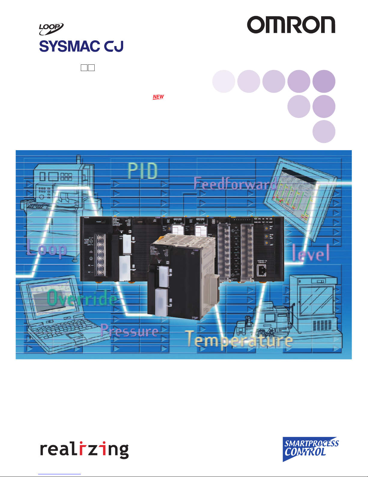
Fully Integrated Sequence and Loop Control
New Built-in Loop Controller
CJ1G-CPU P Loop-control CPU Unit
Unit Version 3.5 (Version Upgrade)
CJ1 Special I/O Units
Process Analog Input Units
(Isolated Units with Fully Universal Inputs)
CJ1W-PH41U (High-resolution Unit) and CJ1W-AD04U (General-purpose Unit)
Series
Programmable Controllers
Page 2
3
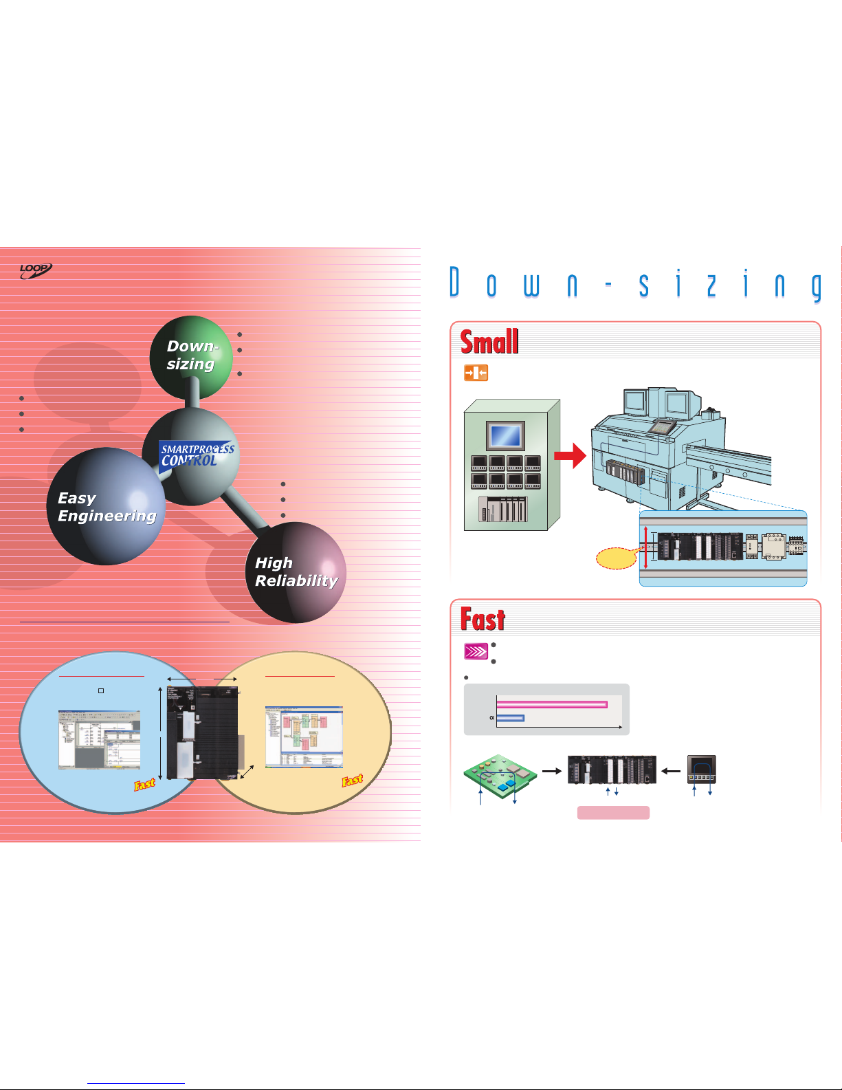
Introducing the New Style of Loop Control
Advanced controller functions integrated with the same CJ-series
functionality and high-speed capabilities
Duct
Duct
90 mm high
S82K G3J J7AN
Power supply SSR Contactor
The same level of high-speed processing
Digital Controller
High-speed processing
(Example: 1-ms response)
High-speed processing
(Example: 50 ms)
SYSMAC CJ-series PLCDedicated microcomputer board
PCMIX Values
CJ1G
SYSMAC
7.4
1.4
Sequencing
Only One CPU Unit Needed
Greatly
reduces space
between ducts
Note: Loop configuration: Ai4 Terminal + Segment Linearizer + Basic PID + Ao4 Terminal
The external I/O response time in the overall system refers to the conversion time.
Ultra-small size fits in most
devices
Backplane-free structure provides
the functions you need in
minimum space.
Low-cost solution for controlling
multiple loops
Control functions have the added
ability to control multiple loops.
Consolidating the proven CSseries loop-control technology
Effective maintenance functions
Function block programming for
easy engineering
Seamless integration of sequence
control and loop control.
HMI windows can be simply
generated from function blocks
automatically.
Super compact: Only 90 mm High and 65 mm Deep, and
Backplane-free structure enables flexible width design.
High-speed sequence control functions can be used directly for
high-speed, advanced loop control.
Compact PLC Aids Machine Downsizing by Fitting Just About Anywhere.
Wide Array of I/O Units, Special I/O Units, and CPU Bus Units Are Available to Suit Your Application.
Sequence control: Executes 20-Kstep ladder programs in 1 ms (with basic instructions only).
PCMIX = 7.4 LD or OUT executed in 40 ns
Loop control: Executes PID operations for 20 loops in up to 10 ms. This is a guide for general
applications.
(See note.)
Integrated Loop Control and Sequence Control
Sequence Control Engine Loop Control Engine
An engine for controlling analog quantities (e.g., temperature, pressure, flowrate) is built into the CPU Unit together
with the engine for executing sequence control, delivering high-speed sequence control and high-speed, advanced
analog quantity control in a single Unit.
CPU Unit element:
CJ1G-CPU4 H
69 mm
D: 65 mm
90 mm
Loop-control
CPU Unit
2
CX-Programmer sequence control program
(ladder, function block, structured text)
Loop Controller Element:
Up to 300 or 50 function blocks
CX-Process loop control program (function blocks)
20-Kstep
1 ms
Execute 20-Kstep ladder
programs in 1 ms
(See note.)
Note: Basic instructions only
20 Loops in 10 ms
Execute PID Control for
20 Loops 10 ms
(See note.)
Note: General application (e.g., loop
configuration: Ai4 Terminal + Segment
Linearizer + Basic PID + Ao4 Terminal)
Page 3
5
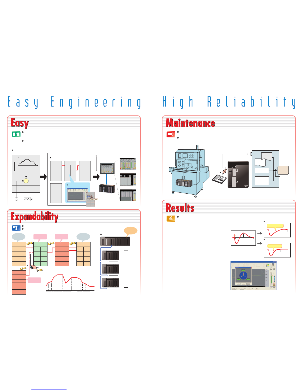
New Algorithm Further Enhances Control
Stability
Disturbance Overshoot Adjustment
Optimum Tuning to Suit the Application
Fine Tuning
Disturbance
Disturbance generated
Time required to
stabilize
Overshoot
Conventional PID gain adjustment
Using the Disturbance
Overshoot Adjustment function
Longer time required
to stabilize
Faster stabilization
This function restrains overshoot when a disturbance is
generated, allowing faster stabilization.
[Example]
• Temperature drops when adding objects to a furnace
• Control disturbances when retooling
Adjust PVs, SPs, and MVs while monitoring, and save
data as CSV files from the software tuning window.
Autotuning (AT) and fine-tuning functions can also be
used for automatically calculating PID constants (see note
2).
Note 1: For details on CS-series Loop Control Boards, refer to the PLC-based
Process Control Catalog (Cat. No. P051).
2: Control can be fine-tuned by automatically tuning PID parameters using
previous control parameters and three user-set requirements to execute
fuzzy logic.
CS-Process Tool Tuning Window
Sequence
program
Function
block
program
I/O memory
Parameter Area
CPU Unit
Memory
Card
Condition: Pin 7 is ON
CX-Process Tool (Software for Personal Computer)
Face Plate Auto-Builder for NS
Touch panel windows are automatically generated.
Segment program
parameter setting window
Tuning window
NT-series PT
Loop-control CPU Unit
Serial or
Ethernet
communications
Control window
SP
TIC
Input
channel 1
Output
channel 1
Time
RSP
PV
MV
Temperature
input
Heater output
Loop-control CPU Unit
Y1
Y2
Y3
Y4
X1
X2
X3
X4
PV
RSP
MV
Analog Output
Field Terminal
Analog Input
Field Terminal
Y1
Segment
Program
Basic PID
Adjust PID and other parameters
in the tuning window.
Expansion Rack
Expansion Rack
Expansion Rack
10 Units max.
10 Units max.
10 Units max.
10 Units max.
Note: CJ1G-CPU44P/45P
(CJ1G-CPU42P/43P: Expand up to 2 Racks)
Analog Input
Field Terminal
MV
DV
SP
PV
Y1
Y2
Y3
Y4
Y5
Y6
Y7
Y8
RSP
Basic PID
Split Conversion
Y1X1
Y2
Y1
X1
Y2
Segment
Program 2
X1
X2
X3
X4
X5
X6
X7
X8
Analog Output
Field Terminal
Function blocks make loop-control programming easy. You can also create
CX-Process Tool tuning windows to help adjust loops. Controller faceplates
can be created automatically for touch panel displays.
Lineup includes low-cost models that use up to 50 function
blocks and models that allow up to 300 blocks designed for
large-scale systems and complicated operations.
Sequence control programs: Standardize and simplify programs using structured programming. Special I/O
Unit and CPU Bus Unit settings are easy with function blocks (using ladder programming language or
structured text).
Loop control programs: By combining function blocks, a wide array of control methods can be easily
configured, from basic PID control used by Temperature Controllers to program, cascade, and feed-forward
control. Easily display values, such as temperatures, in engineering units, allowing you to check operation.
Simple backup function enables backup, recovery, and comparison of all PLC data including the
function block programs for the Loop Control Board using the Memory Card.
Save tag settings, comments, annotations, and connection data created using the CX-Process
Tool to either a Memory Card or a Loop-control CPU Unit.
Loop control: Proven functionality of Temperature Controllers and CS-series Loop Control
Boards (see note 1) in a compact size.
Loop control: Programming with function blocks to suit the application.
System configuration: Choose and combine functions from a broad selection of I/O Units.
Engineering Example: Program Control
Analog
Input
Unit
Analog
Output
Unit
Combine function blocks and connect graphically
using the mouse.
1
2
3
Read data from
Analog Input
Units
Perform PID
control
Perform
heating/cooling
control
Perform program
control
Control output
from Analog
Output Unit
Process Input
Units, Analog
I/O Units, etc.
System Configuration
Expansion
Rack: 3
Racks
max.
(See note.)
Simply turn the DIP Switch ON/OFF to save or read the
user program including function blocks using the
Memory Card.
Consolidating OMRON's expertise in temperature and process control
cultivated over many years to provide you with effortless solutions
using proven algorithms.
Press the
Memory Card
power supply
switch for 3 s.
Simple backup
to Memory
Card, including
function block
data.
Note: Supported by unit version 3.0 or later.
T0 T1 T2 T3 T4 T5 T6 T97 T98 T99 T100 TIME
Set point (SP)
4
Page 4
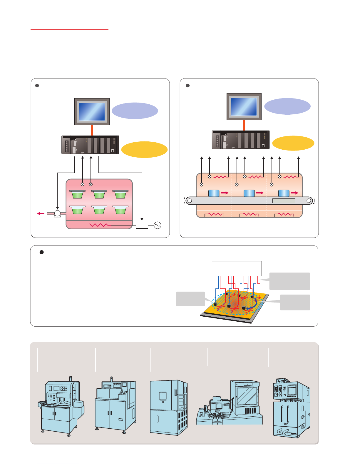
Sterilization and Disinfection of
Pharmaceuticals, Food and Beverages
Loop-control CPU Unit
Loop-control CPU Unit
N2 atmosphere
Solder
Workpiece
Conveyor
NS-series PT
NS-series PT
Heater
Temperature
sensor
SCR
Temperature
Thyristor
Pressure
Control outputsControl outputs
Logging Trend Data
(monitoring and operation
windows)
Monitoring and operation
windows or heaters and
temperature sensors
Program pattern
control
Cascade control of
tunnel furnace
Industrial Furnace
6
Applications
Providing Solutions to Other Problems
The Loop-control CPU Unit Provides You with Solutions for the Complex and Advanced
Functions Demanded by Control Devices in an Increasingly Diverse Range of Equipment.
CPU: CJ1G-CPU45P-GTC
Electrical parts equipment
requiring high-speed
temperature control for
higher precision and
improved tact time.
Diffusion furnaces that
perform cascade control
of heater temperatures
and internal chamber
temperatures.
Food machines, semiconductor devices and
other machines requiring
multipoint temperature
control.
Fermentation equipment
requiring temperature,
pressure, flowrate, and pH
control.
Testing devices that
frequently change
setting conditions and
program settings.
Average
temperature
controlled.
Temperature
differences
controlled.
Interference at other
control output points
suppressed.
Gradient temperature
control
Example: Planar Temperature Control of Multi-stage Furnaces,
Wafer and Glass Surface Temperatures, and Other Applications.
Gradient Temperature Control for Planar
Temperature Control Across Multiple Points
Note: CJ1G-CPU45P-GTC only.
Gradient temperature control equalizes the temperatures at
multiple points, providing high-quality heat processing,
reducing energy loss until temperatures stabilize, and saving
labor in adjustments due to interference between heaters.
For details, refer to the SYSMAC CS/CJ Series Controllers for Gradient
Temperature Control Catalog (R141).
Page 5

7
Process
Loop Control Machines and Product Variations
High-speed and highly reliable (duplex)Easy Controlling analog quantities
CS1D-series
Process-control CPU Unit
(See note 2.)
CS-series/CS1D-S
Loop Control Board
(See note 2.)
CJ1G-CPU4 P CJ-series
Loop-control CPU Unit
Processing facilities
• Chemical/
pharmaceutical
• Utilities
• DCS replacement
• Water treatment
Etc.
• Packaging
machines
• General food
machines
Machinery
• Semi-conductor/
electrical components
• Industrial furnaces
(firing)
• Food machines
(sterilization)
• Testing equipment
Etc.
4 to
20 mA
4 to 20 mA4 to
20 mA
4 to 20 mA
4 to 20 mA
Model Selection
CJ1W-DA
Analog Output Unit
(linear output)
CJ1W-OD
Transistor Output Unit
(pulse output)
CJ1W-OC
Relay Output Unit
RS-485 communications:
Built-in serial port on CPU Unit
CJ1W-SCU 1-V1
E52
Thermocouples
Platinum-resistance
Thermometers
ES1/ES1B
Infrared Thermosensors
Flow Rate Sensors,
Displacement Sensors,
Signal Converters, etc.
• Position Control
G3PX Power Controller
• Cycle Control
G32A-EA + G3PA
• SSR
G3PA/B/C, G3NA, etc.
• ON/OFF Control
• Optimum Cycle Control
G3ZA
CJ1G-CPU P
Loop-control
CPU Unit
CJ1W-P
Analog Process
Input Unit
CJ1W-AD
Analog Input Unit
OutputControlInput
Temperature Sensors
Analog quantities (e.g., temperature,
flowrate, concentration)
Thermocouple
Compensating
Conductor
Sensor Flow Rate Sensor Capacitive
Flow Rate Sensor
PT
Personal computer for
programming/
monitoring
PLC
SYSMAC CJ Series
Compact CJ-series Loop-control CPU units are ideal for equipment with built-in applications. CS-series and CS1D
models designed for duplex systems are also available for processing equipment that requires high reliability.
CJ-series
Temperature Control Unit
(
See note 1.)
Note 1: The Temperature Control Unit integrates control and I/O for either 2 loops or 4 loops.
Temperature control is achieved simply by setting parameters. (CX-Process cannot be used.)
2: For details on CS-series Loop Control Boards and Process-control CPU Units, refer to the PLC-based Process Control Catalog (Cat. No. P051).
System Configuration Example
Example of Peripheral Devices
Page 6
8
Peripheral Devices
Input Devices
Input Devices
Output Devices
Output Devices
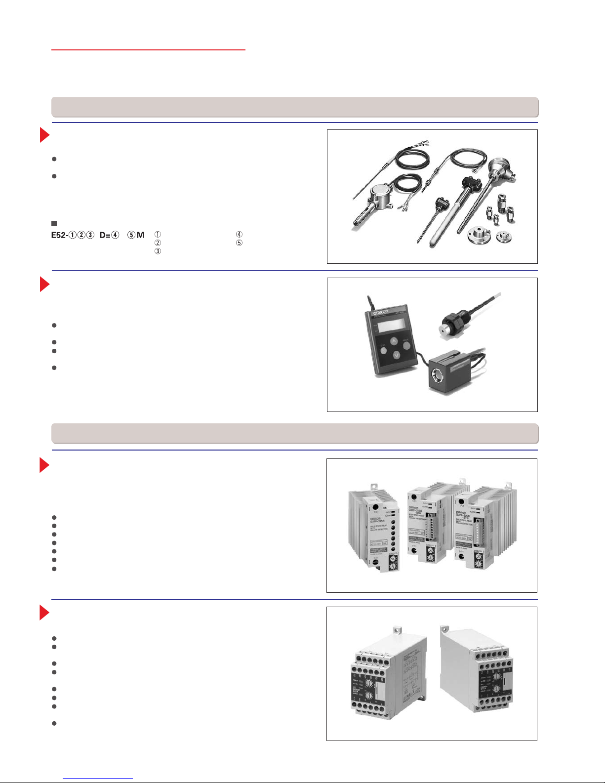
E52-series Temperature Controllers
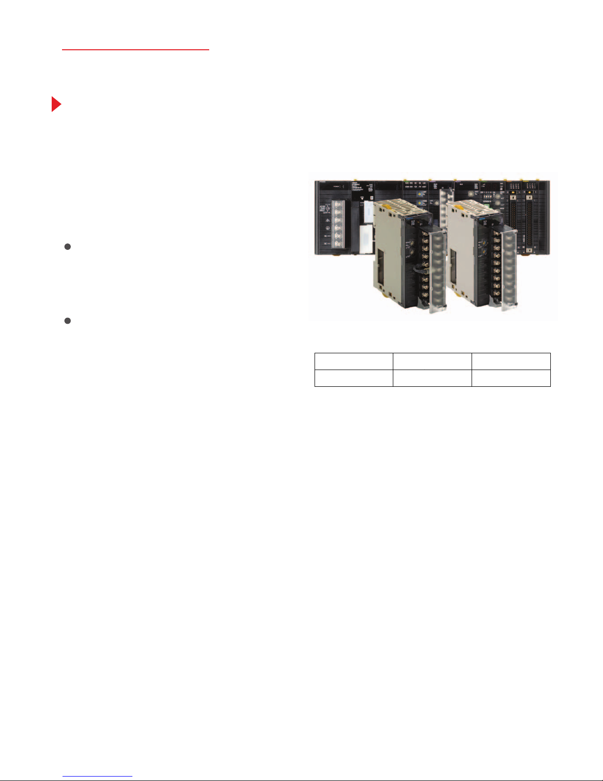
ES1/ES1B-series Infrared Thermosensors
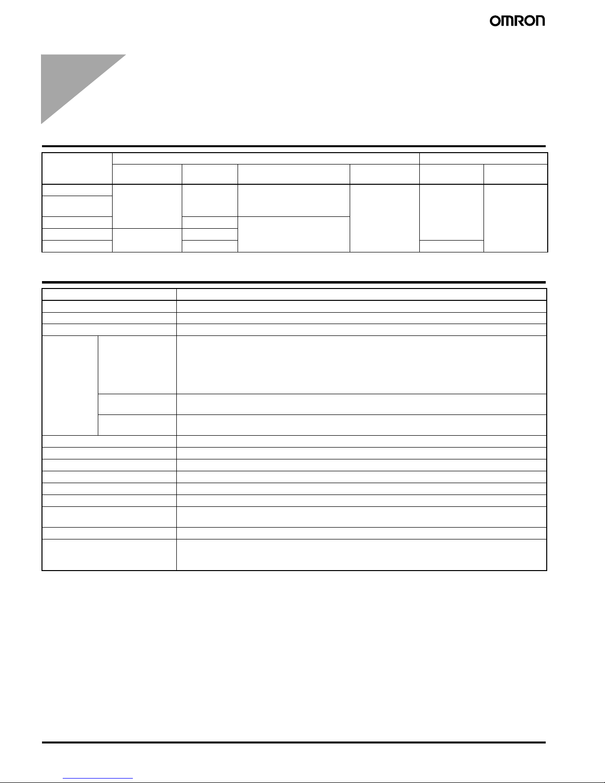
G3PF Solid-state Relay with Built-in
Current Transformer (CT)
Model Structure
Example: E52-CA15A D:3.2 2M
Plenty of Variation to Suit an Extensive Range of Applications
Select from a variety of choices in number of elements, shape, protective
tubing length, and terminal type.
Economical models and special models are available as well as general purpose models. Select from a diverse range of models to suit the application:
Models for high temperatures, metal patterns, surface measurement, and
room temperatures, waterproof and anti-corrosive models, models for moving
parts, and models with double elements.
Hygienic temperature measurement without damaging the workpiece. Ideal for
workpieces on conveyors or other applications in which contact measurement is
difficult.
ES1 Series: Designed for high-precision, small-spot, high-temperature
measurements.
Two types of small spot: 3-mm dia. and 8-mm dia.
High-precision and high-speed measurement with a repeatability of ±0.5°C
and response speed of 0.4 s (95%).
Models are available for medium (–500 to 500°C), mid-low (–50 to 500°C),
and high (0 to 1000°C) temperature ranges.
Built-in current transformer is provided and heater burnouts and SSR shortcircuits can be detected.
Built-in current transformer reduces wiring work.
Detects the burnout of any one of multiple heaters.
Detects burnouts in 3-phase heaters.
Detects SSR short-circuits.
Error detection level can be easily set with a switch.
Can be mounted to a DIN Track or with screws.
Three types of input terminals are available: M3 terminals, screwless clamp
terminals (detachable), or compact slotted terminals (detachable).
G3ZA Multi-channel Power Controller
Optimum Cycle Control for High-precision Control with Low Noise
Smaller than power conditioners.
Power control with little noise is enabled by combining the Power Controller
with zero-cross SSRs. (See note.)
One Controller can control up to 8 SSRs.
RS-485 communications can be used to set output values and heater burnout
detection.
The G3ZA Smart FB Library is also available.
A soft-start function that can be used for lamp heaters has been added. (See note.)
A 3-phase optimum cycle control function has been added for use with 3-cycle
heaters.
Detection of 150-A currents has been added along with a special current
transformer.
Note: Non-zero-cross SSRs must be used in combination with the soft-start function.
Element type
Protective tubing length
Terminal type
Protective tubing model
Lead wire length
Page 7
9
New Products
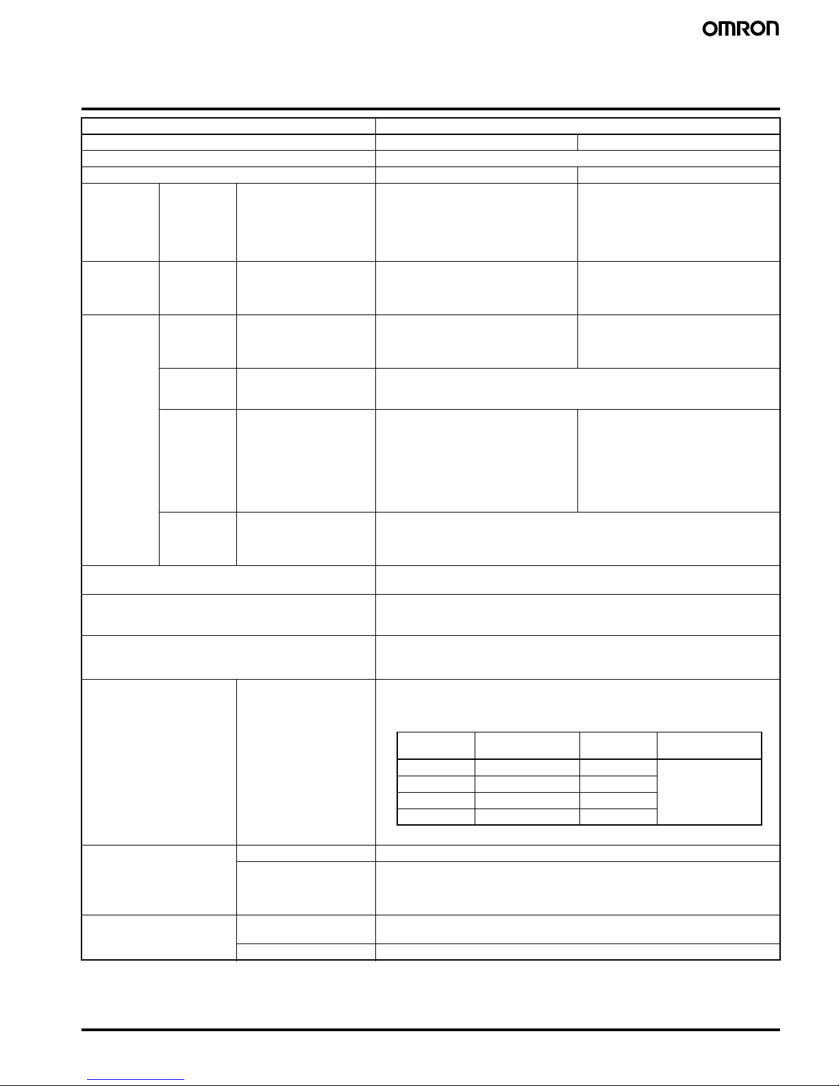
CJ1W-AD04U Process Analog I/O Unit
(General-purpose Unit with Fully Universal Inputs)
CJ1W-PH41U Process Analog I/O Unit
(High-resolution Unit with Fully Universal Inputs)
Fully Universal Inputs, Including Thermocouple
Inputs, Platinum Resistance Thermometer Inputs, and
DC/Voltage Inputs
The input type can be selected for each input channel, saving
space and reducing costs for compact devices that use a mix of
input types. And trouble-free selection of input types improves
inventory control and maintenance.
A single Unit handles all types of inputs, including
temperature sensor inputs (e.g., thermocouple or
platinum resistance thermometer), analog signal
inputs (e.g., 4 to 20 mA or 1 to 5 V), and
potentiometer inputs.
Resolutions and Sampling Speeds for High-resolution Models
Resolution: 1/256,000
60 ms/4 points
Resolution: 1/64,000
10 ms/4 points
Resolution: 1/16,000
5 ms/4 points
General-purpose Models for Great Cost Performance
and High-resolution Models for Applications Such as
Semiconductor Production Equipment
These compact CJ-series Units provide four insolated input
channels per Unit. Depending on the application, choose either the
high-resolution CJ1W-PH41U, which provides a selection of
combinations of resolutions and conversion speeds in addition to
a PLC-first 1/1,000°C range (0.000 to 50.000°C, 4-wire Pt100), or the
general-purpose CJ1W-AD04U, which provides superior cost
performance. (See note.)
Note: According to OMRON investigation.
Page 8
10
Loop-control CPU Units
Loop-control CPU Units
Loop-control CPU Units
Loop-control CPU Units
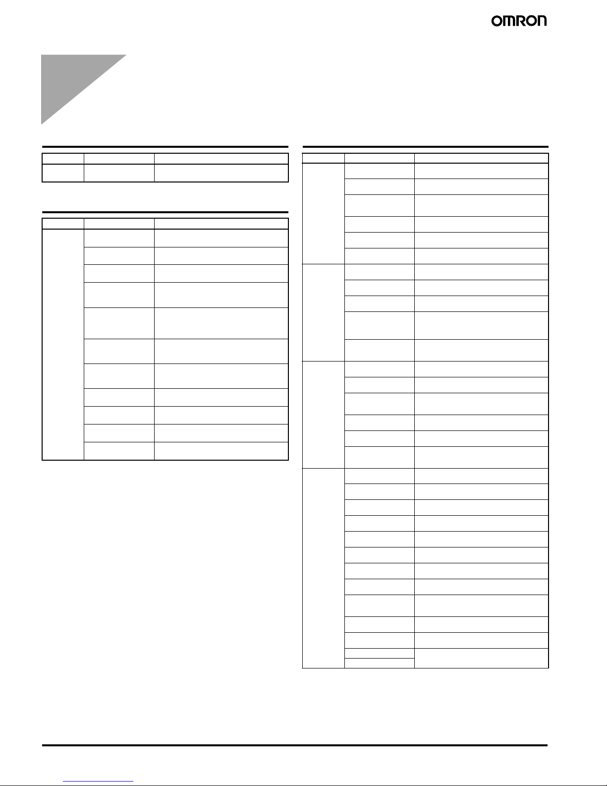
Loop Controller Element Specifications
Model CPU Unit element Loop Controller
I/O capacity Program
capacity
Data memory capacity Programming
software
Number of
function blocks
Programming
software
CJ1G-CPU45P 1,280 points
(Up to 3 Expansion
Racks)
60 Ksteps 128 K words (DM: 32 K words,
EM: 32 K words
× 3 banks)
CX-Programmer,
CX-Simulator, etc.
300 blocks CX-Process
CJ1G-CPU45PGTC
CJ1G-CPU44P 30 Ksteps 64 K words (DM: 32 K words,
EM: 32 K words
× 1 bank)
CJ1G-CPU43P 960 points (Up to 2
Expansion Racks)
20 Ksteps
CJ1G-CPU42P 10 Ksteps 50 blocks
Item Specification
Name Loop-control CPU Unit
Model Number CJ1G-CPU@@P(-GTC)
Applicable PLCs CJ-series PLCs
Area for data
exchange
with CPU Unit
CPU Unit's
Auxiliary Area
• Loop Controller element-to-CPU Unit element:
Run Status Flag, PV Error Input Flag, MV Error Input Flag, Execution Error Flag, Function Block Database (RAM) Error Flag, Automatic Cold Start Execution Flag, Backup during Operation Flag, Function
Block Changed Flag, etc.
• CPU Unit element-to-Loop Controller element:
Start Mode at Power ON: Hot/Cold Start bit.
User allocations in
I/O Memory
User link tables are used to allocate function block ITEM data in any par t of I/O memory in the CPU Unit.
(CIO, Work, Holding, or DM Areas, or EM Area bank 0)
Allocations for all
data
HMI function used to allocate function block ITEM data for Control, Operation, External Controller, and
System Common blocks in the specified bank of the EM Area in the CPU Unit.
Settings None
Indicators Two LED indicators: RUN and ready
Super capacitor backup data All function block data (including sequence tables, step ladder program commands), stored error log data
Super capacitor backup time 5 minutes at 25
°C
Data stored in flash memory Function block data
Backup from RAM to flash memory Executed from CX-Process Tool (as required).
Recovery from flash memory to
RAM
Automatically transferred when power to CPU Unit is turned ON if startup mode is set for a cold start, or
executed from CX-Process Tool (as required).
Influence on CPU Unit cycle time 0.8 ms max. (depends on function block data contents)
Current consumption (supplied
from Power Supply Unit)
1.06 A for 5 VDC (current consumption for Loop-control CPU Unit including CPU Unit element and Loop
Controller element)
Note: Increased by 150 mA when NT-AL001 Link Adapter is used.
Page 9
11
Loop-control CPU Units
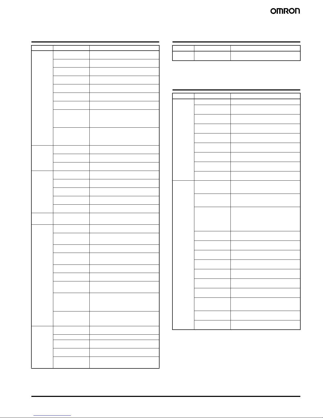
Loop Controller Element Specifications
Loop Controller Element Specifications
Item Specifications
Model CJ1G-CPU42P CJ1G-CPU43/44/45P(-GTC)
Operation method Function block method
Loop Controller element LCB01 LCB03
Function
block analog
operations
Control and
operation
blocks
PID and other control
functions, square root operation, time operations,
pulse train operation, and
other operation functions
for various processes.
50 blocks max. 300 blocks max.
Sequence
control
Step ladder
program
blocks
Logic sequence and step
sequence functions
20 blocks max.
2,000 commands total
100 commands max. per block
Separable into 100 steps max.
200 blocks max.
4,000 commands total
100 commands max. per block
Separable into 100 steps max.
I/O blocks Field terminal
blocks
Analog I/O function with
Analog I/O Unit, contact
I/O function with Basic I/O
Unit
30 blocks max. CJ1G-CPU43P: 30 blocks max.
CJ1G-CPU44/45P: 40 blocks max.
User link
tables
Analog data I/O and contact data I/O function for
CPU Unit
2,400 data items max.
HMI function I/O function for the speci-
fied bank of the EM Area
in the CPU Unit for function block ITEM data used
for Control, Operation,
External Controller, and
System Common blocks
for the HMI function.
Allocated 1 EM Area bank
Operation and Control blocks:
50 blocks max.
× 20 send/receive words
System Common blocks:
20 send/receive words
Allocated 1 EM Area bank
Operation and Control blocks:
300 blocks max.
× 20 send/receive words
System Common blocks:
20 send/receive words
System
Common
block
System common operation cycle setting, run/
stop command, load rate
monitor, etc.
Single block
Method for creating and transferring function blocks Created using CX-Process Tool (purchased separately) and transferred to Loop
Controller.
External I/O response time The time from external input of analog signals up to external output of analog signals
on a single control loop depends on the function block's operation cycle and the
CPU Unit's cycle time.
Operation cycle 0.01, 0.02, 0.05, 0.1, 0.2, 0.5, 1, or 2 s (default: 1 s) (See note.)
Can be set for each function block.
Note: 0.01, 0.02, and 0.05 s cannot be set for some blocks.
Internal operation Number of control loops • The maximum number of loops that can be used if the LCB load rate is 80% for a
standard applications (e.g., with each loop consisting of one Ai4 Terminal, Segment Linearizer, Basic PID, and A04 terminal) is shown in the following table.
Note: Loop Controller element LCB01: 25 loops max.
Control method PID control method PID with 2 degrees of freedom
Control combinations Any of the following function blocks can be combined:
Basic PID control, cascade control, feed-forward control, sample PI control, Smith
dead time compensation control, PID control with differential gap, override control,
program control, time-proportional control, etc.
Alarms PID block internal alarms 4 PV alarms (upper upper-limit, upper limit, lower limit, lower lower-limit) and 1
deviation alarm per PID block
Alarm blocks High/low alarm blocks, deviation alarm blocks
Operation
cycle
Maximum number
of loops
Operation
cycle
Maximum number
of loops
0.01 s 20 loops 0.2 s 150 loops
(See note.)
0.02 s 35 loops (see note) 0.5 s
0.05 s 70 loops (see note) 1 s
0.1 s 100 loops (see note) 2 s
Page 10
12
List of Function Blocks
System Common Block
List of Function Blocks
System Common Block
Control Blocks
Note: 1. The Function Blocks dealing with high-speed operation
(operation cycle: 0.01, 0.02, and 0.05 seconds is possible).
2. Cannot be used with the CJ1G-CPU45P-GTC.
Operation Blocks
Type Block Name Function
--- System Common Makes settings common to all function
blocks and outputs signals for the system.
Type Block Name Function
Controller 2-position ON/OFF
(See note 1.)
2-position type ON/OFF controller
3-position ON/OFF
(See note 1.)
3-position type ON/OFF controller for
heating/cooling ON/OFF control
Basic PID
(See note 1.)
Performs basic PID control.
Advanced PID
(See note 1.)
Performs advanced PID control for
enabling deviation/MV compensation,
MV tracking, etc.
Blended PID
(See note 2.)
Performs PID control on the cumulative
value (cumulative deviation) between the
accumulated value PV and accumulated
value Remote Set Point.
Batch Flowrate
Capture (See note 2.)
Functions to open the valve at a fixed opening until a fixed batch accumulated value is
reached.
Fuzzy Logic
(See note 2.)
Outputs up to 2 analog outputs based on
fuzzy logic performed on up to 8 analog
inputs.
Indication and Setting
(See note 1.)
Manual setter with PV indication and SP
setting functions
Indication and Operation (See note 1.)
Manual setter with PV indication and MV
setting functions
Ratio Setting
(See note 1.)
Ratio and bias setter w ith PV indication and
ratio setting function
Indicator
(See note 1.)
PV indicator with PV alarm
Type Block Name Function
Alarm/Signal
restrictions/
Hold
High/Low Alarm
(See note 1.)
Provides the alarm contact outputs for the high
and low limits of single analog signals.
Deviation Alarm
(See note 1.)
Provides the alarm contact outputs for the deviation of two analog signals.
Rate-of-change Operation and Alarm
(See note 1.)
Provides the alarm contact outputs for the high
and low limits of rate-of-change operation when
the analog signal rate-of-change is output.
High/Low Limit
(See note 1.)
Limits the high and low limits of single analog
signals.
Deviation Limit
(See note 1.)
Calculates the deviation between two analog
signals, and limits the deviation within that range.
Analog Signal Hold
(See note 1.)
Holds the maximum, minimum or instantaneous
value of single analog signals.
Arithmetic Addition or Subtraction
(See note 1.)
Performs addition/subtraction with gain and bias
on up to 4 analog signals.
Multiplication
(See note 1.)
Performs multiplication with gain and bias on up to
2 analog signals.
Division (See note 1.) Performs division with gain and bias on up to 2
analog signals.
Arithmetic Operation
(See note 1.)
Performs various math operation (trigonometric,
logarithmic, etc.) on floating-point decimal values
converted (to industrial units) from up to 8 analog
inputs.
Range Conversion
(See note 1.)
Easily converts up to 8 analog signals simply by
inputting the 0% and 100% input values and 0%
and 100% output values.
Functions Square Root
(See note 1.)
Performs square root extraction (with low end
cutout) on single analog signals.
Absolute Value
(See note 1.)
Outputs the absolute value of single analog signals.
Non-linear Gain
(Dead Band)
(See note 1.)
Performs non-linear (3 gain values) operation on
single analog signals. Analog signals can also set
as a dead band (with different gap).
Low-end Cutout
(See note 1.)
Sets output to zero close to the zero point of single
analog signals.
Segment Linearizer
(See note 1.)
Converts single analog signals to 15 segments
before the signals are output.
Temperature and
Pressure Correction
(See note 1.)
Performs temperature and pressure correction.
Time Function First-order Lag
(See note 1.)
Performs first-order lag operation on single analog
signals.
Rate-of-change Limit
(See note 1.)
Performs rate-of-change restriction on single
analog signals.
Moving Average
(See note. 1)
Performs moving average operation on single
analog signals.
Lead/Delay (See note 1.) Performs lead/delay operation on single analog
signals.
Dead Time (See note 1.) Performs dead time and first-order lag operations
on single analog signals.
Dead Time Compensation
Used for Smith's dead time compensation PID
control.
Accumulator for instantaneous value input
Accumulates analog signals, and outputs 8-digit
accumulated value signals.
Run Time Accumulator Accumulates the operating time, and outputs the
pulse signal per specified time.
Time Sequence Data
Statistics (See note 1.)
Records time sequence data from analog signals
and calculates statistics, such as averages and
standard deviations.
Ramp Program Ramp program setter for combining ramps for time
and hold values.
Segment Program Segment program setter setting the output values
with respect to time.
Segment Program 2 Segment program setting with wait function for
setting the output values with respect to time.
Segment Program 3
Page 11
13
List of Function Blocks
Note: 1. The Function Blocks dealing with high-speed operation
(operation cycle: 0.01, 0.02, and 0.05 seconds is possible).
2. Cannot be used with the CJ1G-CPU45P-GTC.
Sequence Control
Note: The Function Blocks dealing with high-speed operation (oper-
ation cycle: 0.01, 0.02, and 0.05 seconds is possible).
Field Terminals
Note: The Function Blocks dealing with high-speed operation
(operation cycle: 0.01, 0.02, and 0.05 seconds is possible).
Type Block Name Function
Signal Selection/Switching
Rank Selector
(See note 1.)
Selects the rank of up to 8 analog signals.
Input Selector
(See note 1.)
Selects the specified analog signals specified by
the contact signal from up to 8 analog signals.
3-input Selector
(See note 1.)
Selects and outputs one of three analog input
signals.
3-output Selector
(See note 1.)
Outputs one analog input signal in three switched
directions.
Constant Selector
(See note 1.)
Selects 8 preset constants by the contact signal.
Constant Generator
(See note 1.)
Outputs 8 independent constants.
Ramped Switch Switches two analog inputs (or constants) with a
ramp.
Bank Selector Records the PID parameters (SP, P, I, D, MH, ML)
in up to 8 sets in advance, and switches the PID
parameter for Basic/Advanced/Blended PID
Blocks according to the analog input range
(zone) or input bits.
Split Converter Inputs the MV from the Basic PID block or Ad-
vanced PID block, converts the MV into two
analog outputs for V characteristics or parallel
characteristics (e.g., MV for heating or cooling)
and outputs them.
Constant
ITEM Setting
Constant ITEM Setting
(See note 1.)
Writes the constant to the specified ITEM at the
rising edge of the send command contact.
Variable ITEM Setting
(See note 1.)
Writes the analog signal to the specified ITEM at
the rising edge of the send command contact.
Batch Data Collector
(See note 1.)
Stores each of max. 8 analog inputs to buffer by
a certain timing within sequential processing.
Pulse Train
Operation
Accumulated Value Input Adder
Adds up to four accumulated value signals.
Accumulated Value Analog Multiplier
Multiplies analog signals by the accumulated
value signals.
Accumulator for accumulated value input
Converts 4-digit accumulated value signals to 8
digits.
Contact input/Accumulated value output
Counts low-speed contact pulses, and outputs
8-digit accumulated signals.
Accumulated Value Input/Contact Output
Converts 4-digit accumulated value signals to
low-speed contact pulses before they are output.
Others Analog/Pulse Width
Converter (See note 1.)
Changes the ON/OFF duration ratio in a constant
cycle duration so that it is proportional to the
analog signal.
Sequence
Operation
Contact Distributor Connect contact signals between function blocks
in a 1:1 connection.
Constant Comparator
(See note 1.)
Compares up to eight sets of analog signals and
constants, and outputs the comparison results as
contacts.
Variable Comparator
(See note 1.)
Compares up to eight pairs of analog signals,
and outputs the comparison results as contacts.
Timer (See note 1.) 2-stage output type addition timer for forecast
values and reached values. Can also output the
present value.
ON/OFF Timer
(See note 1.)
Timer for performing ON-OFF operation at preset
ON and OFF times.
Clock Pulse
(See note 1.)
Outputs a clock pulse at the setting time interval
for a single operation cycle.
Counter (See note 1.) 2-stage output type addition timer for forecast
values and arrival values. Can also output the
current va lue.
Internal Switch
(See note 1.)
Temporary storage contact for accepting relays in
the Step Ladder Program block.
Note: (One internal switch is already allocated
as “temporary storage” in CX-Process
To ol .)
Level Check
(See note 1.)
Checks an analog input for 8 levels and outputs
a contact corresponding to the level. The level
number is also output as an analog value at the
same time.
Contact Type
Control Target
ON/OFF Valve Manipulator
Manipulates and monitors ON/OFF valves with
open/close limit switches.
Motor Manipulator Manipulates and monitors motor operation.
Reversible Motor Manipulator
Manipulates and monitors reversible motor
operation.
Motor Opening Manipulator
Inputs a target opening, and manipulates an
electric positional-proportional motor.
Switch Meter
(See note 2.)
Manipulates and monitors multiple (up to 8)
devices such as ON/OFF valves, motors, or
pumps.
Type Block Name Function
--- Step Ladder Program (See note.)
Performs logic sequence and step progression control.
Type Block Name Function
Contact
I/O
(See note.)
DI 8-point Terminal Inputs 8 contacts from 8-point Input Unit.
DI 16-point Terminal Inputs 16 contacts from 16-point Input
Unit.
DI 32-point Terminal Inputs 32 contacts from 32-point Input
Unit.
DI 64-point Terminal Inputs 64 contacts from 64-point Input
Unit.
DO 8-point Terminal Outputs 8 contacts from 8-point Output
Unit.
DO 16-point Terminal
Outputs 16 contacts from 16-point Output
Unit.
DO 32-point Terminal
Outputs 32 contacts from 32-point Output
Unit.
DO 64-point Terminal
Outputs 64 contacts from 64-point Output
Unit.
DI 16-point/Do
16-point Terminal
Inputs and outputs 16 contacts each from
16-point Input/16-point Output Units.
Analog I/O
(See note.)
AI 4-point Terminal
(PTS51)
Inputs 4 analog signals from CJ1WPTS51 (Isolated-type Thermocouple
Input Unit)
AI 4-point Terminal
(PTS52)
Inputs 4 analog signals from CJ1WPTS52 (Isolated-type Temperature Resistance Input Unit).
AI 2-point Terminal
(PTS15/16, PDC15)
Inputs 2 analog signals from CJ1WPTS15 (Isolated-type Thermocouple
Input Unit), CJ1W-PTS16 (Isolated-type
Temperature Resistance Input Unit), or
CJ1W-PDC15 (Isolated-type DC Input
Unit).
AI 8-point Terminal
(AD081)
Inputs 8 analog signals from the CJ1WAD081(-V1).
AO 8-point Terminal
(DA08V/C)
Outputs 8 analog signals from the CJ1WDA08V/DA08C.
AI 4-point Terminal
(AD041)
Inputs 4 analog signals from the CJ1WAD041(-V1).
AO 4-point Terminal
(DA041)
Outputs 4 analog signals from the CJ1WDA041(-V1).
AO 2-point Terminal
(DA021)
Outputs 4 analog signals from the CJ1WDA021.
AI 4-point/AO 2-point
Terminal (MAD42)
Inputs 4 analog signals and outputs 2 analog signals each from the CJ1W-MAD42.
AI 4-point Terminal
(DRT1-AD04)
Inputs 4 analog signals from a DRT1AD04 DeviceNet Slave Analog Input Unit.
AO 2-point Terminal
(DRT 1-DA02)
Outputs two analog signals from a DRT1DA02 DeviceNet Slave Analog Output
Unit.
AI 4-point Terminal
(AD04U)
Inputs 4 analog signals from the CJ1WAD04U.
AI 4-point Terminal
(PH41U)
Inputs 4 analog signals from the CJ1WPH41U.
Page 12

14
CX-Process Tool and Monitor
Software Specifications
CX-Process Tool and Monitor
Software Specifications
Item
Specifications
CX-Process Tool CX-Process Monitor Plus
Name CX-Process CX-Process Monitor Plus
Model number WS02-LCTC1-EV5 WS02-LCMC1-EV2
Applicable PLCs CS-series PLCs
CJ-series PLCs
Applicable Units CJ-series Loop-control CPU Units
CS-series Loop Control Units/Boards
CS1D Process-control CPU Units
CJ-series Loop-control CPU Units
CS-series Loop Control Units/Boards
CS1D Process-control CPU Units
Compatible computers
Computer IBM PC/AT or compatible
CPU Intel CPU (Core, Pentium, or Celeron family)
For Windows Vista: 1 GHz min.
For any other OS: 333 MHz min. required, 1 GHz min. recommended
OS Microsoft Windows 2000 (Service Pack 3 or higher), NT4.0
(Service Pack 6a), 98SE, Me (See note 1), XP, or Vista (Ultimate or Business)
Microsoft Windows 2000, NT4.0, or XP
Memory For Windows Vista, 1 GB min.
For any other OS: 256 MB min. required, 512 MB min. recommended
Minimum: 96 Mbytes
Recommended: 128 Mbytes min.
Hard disk storage Min. required: 350 Mbytes of free space,
Recommended: 450 Mbytes or more of free space (including approx. 280 Mbytes used by communications middleware)
Minimum: 650 Mbytes free space
(Including approximately 50 Mbytes used for
communications middleware and other purposes)
Monitor Minimum: XGA
Recommended: SXGA 65,536 colors or more
Minimum requirement: XGA
(XGA or above recommended)
CD-ROM drive 1 drive min.
Sound board --- 1
Mouse Recommended: Microsoft mouse or compatible pointing device
Communications
method
Connection with CPU Unit
(or Serial Communications Board/Unit)
When FinsGateway Serial Unit driver is used:
Communications protocol with PLC: Host Link or Peripheral Bus (See note 2.)
• Connect the computer to the peripheral port or built-in RS-232C port of the CPU Unit, or to the
RS-232C port of the Serial Communications Board/Unit.
• Connecting cable:
For connecting to peripheral port of CPU Unit: CS1W-CN@@@ (2 m or 6 m)
For connecting to RS-232C port of CPU Unit: XW2Z-@@@-@ (2 m or 5 m)
When CX-Server is used:
Communications protocol with PLC: Host Link or Peripher-
al Bus
Connecting Cable:
• For connecting to peripheral port of CPU Unit:
CS1W-CN@@@ (2 m or 6 m)
For connecting to RS-232C port of CPU Unit:
XW2Z-@@@-@ (2 m or 5 m)
CX-Server is not supported.
Connection via Controller
Link
When FinsGateway Controller Link driver or CX-Server is used:
Install the software in a computer with a Controller Link Support Board to communicate with a PLC with a
Controller Link Unit mounted.
Connection via Ethernet When FinsGateway ETN_UNIT driver or CX-Server is used:
Install the software in a computer with an Ethernet Board to communicate with a PLC with an Ethernet Unit
mounted.
Page 13

15
CX-Process Tool and Monitor
Connections to PLC
Note: The CX-Process functions that can be used depend on the version. For details, refer to the operation manuals (Cat. No.: W372-E1-@ and
W373-E1-@).
Note: 1. When using Windows Me, the CPU must be a Pentium 150 MHz or higher.
2. Peripheral Bus cannot be used when FinsGateway V3 is used.
Connections to PLC
The following 4 methods can be used to connect to a PLC.
Note: 1. The Windows 2000 and XP operating systems are supported. (Windows 95, 98, and Me are not supported.)
2. When CX-Server is used for communications, CX-Programmer can be simultaneously connected via the same COM port.
3. The Windows 95 operating system cannot be used.
Item
Specifications
Offline functions ITEM data settings for function blocks
• Software connections for analog signals
• Displaying and printing text strings (annotation)
pasted on function block diagrams and ladder
diagrams.
• Instructions for step ladder blocks and commands for
sequence table blocks
• Tag settings for CX-Process Monitor
• Engineering unit display setting
• Segment Program parameter setting
Construction of user screens
Online functions • Transfer of function block data (Downloading/Upload-
ing for Loop Control Boards/Units.)
• Starting/stopping all function blocks (LCU/LCB)
• Monitoring system operation: Monitoring and
controlling the System Common block (including
LCB/LCU load rates)
• Validating LCB/LCU operation: Checking function
block connections (including starting and starting
individual function blocks), validating ladder
diagrams and sequence tables, and monitoring
ITEMs
• Tuning PID constants and other parameters
(fine tuning and autotuning)
• Initialization of Loop Control Unit memory (RAM)
• External backup specifications
User screens
• Overview screen
• Control screen
• Tuning screen
• Trend screen
• Graphic screen
• Operating guide message screen
System screens
• Alarm history screen
• System monitor screen
• Operation log screen
Communications network Communication driver
FinsGateway V3 FinsGateway Version
2003 (See note 1.)
CX-Server V2.2
Host Link Connection via PLC's peripheral port or
RS-232C port
Supported. (Serial Unit version is used.) Supported.
(See note 2.)
Peripheral Bus Not supported. Supported. Supported.
(See note 2.)
Controller Link Connection to PLC with Controller Link Unit
via Controller Link Support Board (PCI
board).
Supported. (See note 3.)
(CLK (PCI) version is used.)
Supported.
Connection to PLC with Controller Link Unit
via Controller Link Support Board (ISA
board).
Supported. (CLK (ISA) version is used.) Supported.
Ethernet Connection to PLC with Ethernet Unit via
Ethernet Board.
Supported. (Ethernet version is used.) Supported.
Page 14

16
Utility Software
Touch Panel Software
Utility Software
Touch Panel Software
■ Face Plate Auto-Builder for NS
Simply specify the CSV tag file created using the CX-Process Tool to automatically create a project constructed with a Face Plate for Loop-control
CPU Units for use with OMRON's NS-series Programmable Terminals.
Function Overview
• Create windows for monitoring and tuning PID and other function blocks for up to 100 loops (NS System version 4 or higher).
• NS project files for monitoring multiple Loop-control CPU Units from a single NS-series PT can be generated from CX-Process projects for up to
32 multiple nodes.
• When a Segment Program 2 or 3 function block is used for program operation, the Detailed Setting Windows (Time Interval vs. Output Value
Setting Window, Wait Interval Setting Window) used for the parameter settings are also automatically generated.
• NS-Runtime is supported.
Basic Specifications
Example of Automatically Created Windows
Item Specifications
Name Face Plate Auto-Builder for NS
Model number WS02-NSFC1-EV3
Applicable PLC products CJ-series Loop-control CPU Units
CS-series Loop Control Boards (unit version 1.0 or later)
CS-series Loop Control Units (unit version 2.0 or later)
CS1D Process-control CPU Units
Applicable PTs NS-series NS12, NS10, and NS8 (PT version 2.0 or later), CX-Designer
System
requirements
Computer IBM PC/AT or compatible
CPU Celeron 400 MHz or better recommended
OS Microsoft Windows 98SE, NT4.0 (Service Pack 6a), 2000 (Service Pack 3 or later), or XP
Memory Recommended: 32 Mbytes min.
Hard disk storage Recommended: 200 Mbytes free space min.
Monitor Minimum: 640
× 480 dots
Basic functions Number of generated loops:100 max., control windows and tuning windows
Applicable face plates: 2-position ON/OFF, 3-position ON/OFF, Basic PID, Advanced PID, Indication and
Operation, Indicator, Segment Program 2 (includes the parameter setting windows),
Segment Program 3 (includes the parameter setting windows)
Number of loops in control windows: 6 loops per window for NS12, 4 loops per window for NS10/NS8
Realtime trend in tuning window: 1-second cycle
Tuning Window
Basic PID Block Screen
Segment program details setting window
MV numerical value
display/input
MAN button/display
AUTO button/display
Time interval,
output value,
and unit for
each step
Setting confirmation
graph (horizontal axis
shows steps)
Up/Down buttons to change SP
SP bar display
CAS button/display
Unit display
SP numerical value display/input
PV numerical value display
Status display 2
(PV error, MV error)
Status display 1
(AUTO, MAN, CAS)
Tag No .
Tag comment
Alarm status
indicators
PV bar display
Alarm set
value display
MV indicator
MV bar display
Up/Down
buttons to change
MV
To Tuning Window
To Control
Window
Write/read setting data
Realtime trend
display
Switch status
Alarm setting Parameter settings
Function
Block Face
Plate
Page 15

17
Dimensions
CPU Units
Dimensions
CPU Units
■ Loop-control CPU Units
CJ1G-CPU42P
CJ1G-CPU43P
CJ1G-CPU44P
CJ1G-CPU45P(-GTC)
■ Process Input Units
CJ1W-P@@@@
CONTROLLER
CJ1G-CPU44P
SYSMAC
PROGRAMMABLE
ERR/ALM
RUN
COMM
INH
PRPHL
OPEN
PERIPHERAL
BUSY
MCPWR
PORT
65
69 73.9
2.7
2.7
90
LCB03
EXEC
RDY
INNER LOOP CONTROLLER
MACH
No.
PTS51
B1 A1
RUN
ERC
ERH
89
65
31
2.7
90
2.7
Page 16

18
Ordering Information
Basic Configuration Units
Ordering Information
Basic Configuration Units
■ CJ1 Loop Control Units
■ CJ1 CPU Units
Product name Specifications Current
consumption
(A)
Model Standards
CPU Unit Loop Controller 5 V 24 V
CJ1G Loopcontrol CPU
Units
Same as for CJ1G-CPU45H Number of function blocks:
300 blocks max.
1.06
(See
note
1.)
---
CJ1G-CPU45P
UC1, CE
CJ1G-CPU45P-GTC
Same as CJ1G-CPU44H
1.06
(See
note
1.)
--- CJ1G-CPU44P
Same as CJ1G-CPU43H
1.06
(See
note
1.)
--- CJ1G-CPU43P
Same as CJ1G-CPU42H Number of function blocks:
50 blocks max.
1.06
(See
note
1.)
--- CJ1G-CPU42P
Product name Specifications Current
consump-
tion (A)
Model Standards
I/O capacity/
Mountable-
Units (Expan-
sion Racks)
Program
capacity
Data memory
capacity
LD instruction execu-
tion time
5 V 24 V
CJ1-H-R CPU
Units
2,560 points/
40 Units
(3 Expansion
Racks max.)
250K steps 448K words
(DM: 32K words,
EM: 32K words
× 13
banks)
0.016
µs0.99
(See
note
1.)
---
CJ1H-CPU67H-R
UC1, N, L,
CE
120K steps 256K words
(DM: 32K words,
EM: 32K words
× 7
banks)
0.99
(See
note
1.)
---
CJ1H-CPU66H-R
60K steps 128K words
(DM: 32K words,
EM: 32K words
× 3
banks)
0.99
(See
note
1.)
---
CJ1H-CPU65H-R
30K steps 64K words
(DM: 32K words,
EM: 32K words
× 1 bank)
0.99
(See
note
1.)
---
CJ1H-CPU64H-R
Page 17

19
Ordering Information
Basic Configuration Units
Note: 1. Current consumptions include current for a Programming Console. Add 0.15 A per Adapter when using NT-AL001 RS-232C/RS-422A
Adapters. Add 0.04 A per Adapter when using CJ1W-CIF11 RS-422A Adapters.
2. Some specifications of the low-end CJ1M (CJ1M-CPU11/21) differ from those of the CJ1M-CPU12/13/22/23 as shown in the following
table.
CJ1H-H CPU Units 2,560 points/
40 Units
(3 Expansion
Racks max.)
250K steps 448K words
(DM: 32K words,
EM: 32K words
×13
banks)
0.02
µs0.99
(See
note
1.)
--- CJ1H-CPU67H UC1, N, L,
CE
120K steps 256K words
(DM: 32K words,
EM: 32K words
× 7
banks)
0.99
(See
note
1.)
--- CJ1H-CPU66H
60K steps 128K words
(DM: 32K words,
EM: 32K words
× 3
banks)
0.99
(See
note
1.)
--- CJ1H-CPU65H
CJ1G-H CPU Units 1,280 points/
40 Units
(3 Expansion
Racks max.)
60K steps
128K words
(DM: 32K words,
EM: 32K words
× 3
banks)
0.04
µs0.91
(See
note
1.)
--- CJ1G-CPU45H UC1, N, L,
CE
30K steps 64K words
(DM: 32K words,
EM: 32K words
× 1 bank)
0.91
(See
note
1.)
--- CJ1G-CPU44H
960 points/
30 Units
(2 Expansion
Racks max.)
20K steps 0.91
(See
note
1.)
--- CJ1G-CPU43H
10K steps 0.91
(See
note
1.)
--- CJ1G-CPU42H
CJ1M
CPU
Units
Without
built-in
I/O
640 points/
20 Units
(1 Expansion
Rack max.)
20K steps 32 K words
(DM: 32K words,
EM: None)
0.1
µs0.58
(See
note
1.)
--- CJ1M-CPU13 UC1, N, L,
CE
320 points/
10 Units
(No Expansion
Rack)
10K steps 0.58
(See
note
1.)
--- CJ1M-CPU12
160 points/
10 Units
(No Expansion
Rack)
5K steps 0.58
(See
note
1.)
--- CJ1M-CPU11
(See note 2.)
Product name Specifications Current
consump-
tion (A)
Model Standards
I/O capacity/
Mountable-
Units (Expan-
sion Racks)
Program
capacity
Data memory
capacity
LD instruction execu-
tion time
5 V 24 V
Page 18

20
Ordering Information
Basic Configuration Units
■ CJ1 CPU Units (with Built-in I/O)
Note: 1. Current consumptions include current for a Programming Console. Add 0.15 A per Adapter when using NT-AL001 RS-232C/RS-422A
Adapters. Add 0.04 A per Adapter when using CJ1W-CIF11 RS-422A Adapters.
2. Some specifications of the low-end CJ1M (CJ1M-CPU11/21) differ from those of the CJ1M-CPU12/13/22/23 as shown in the following
table.
3. The connector for built-in I/O in the CJ1M-CPU21/22/23 is not included. Purchase one of the connectors or connector cables in the following table separately.
Product name Specifications Current
consump-
tion (A)
Model Standards
I/O capacity/
Mountable-
Units (Expan-
sion Racks)
Program
capacity
Data memory
capacity
LD instruction execu-
tion time
Built-in I/O 5 V 24 V
CJ1M
CPU
Units
With
built-in
I/O
(See note
2.)
640 points/
20 Units
(1 Expansion
Rack max.)
20K steps 32K words
(DM: 32K
words,
EM: None)
0.1
µs 10 inputs
and 6 outputs,
2 counter
inputs, 2
pulse outputs
0.64
(See
note
1.)
---
CJ1M-CPU23
(See note 3.)
UC1, N, L,
CE
320 points/
10 Units
(No Expansion
Rack)
10K steps 0.64
(See
note
1.)
---
CJ1M-CPU22
(See note 3.)
160 points/
10 Units
(No Expansion
Rack)
5K steps 0.64
(See
note
1.)
---
CJ1M-CPU21
(See notes 2
and 3.)
CJ1M-CPU11 CJ1M-CPU12
CJ1M-CPU13
CJ1M-CPU21 CJ1M-CPU22
CJ1M-CPU23
Overhead time
0.7 ms 0.5 ms 0.7 ms 0.5 ms
Pulse start time
--- --- 63 µs
(without acceleration/deceleration, continuous)
46
µs
(without acceleration/deceleration, continuous)
100
µs
(trapezoidal control)
70 µs
(trapezoidal control)
Number of subroutines
and jumps
256 1024 256 1024
Number of scheduled
interrupt tasks
121 2
Number of PMW
outputs
--- --- 1 2
Page 19

21
Ordering Information
Basic Configuration Units
■ Power Supply Units
One Power Supply Unit is required for each Rack.
Product name Power
supply
voltage
Output capacity Options Model Standards
5-VDC
output
capacity
24-VDC
output
capacity
Tota l
power
consump-
tion
24-VDC
service
power
supply
RUN
out-
put
Maintenance
forecast
monitor
AC
Power
Supply
Units
100 to
240 VAC
5 A 0.8 A 25 W No No Yes CJ1W-PA205C UC1, N, L,
CE
Yes No CJ1W-PA205R
2.8 A 0.4 A 14 W No No CJ1W-PA202
DC
Power
supply
Units
24 VDC 5 A 0.8 A 25 W No No CJ1W-PD025
2 A 0.4 A 19.6 W No No CJ1W-PD022 UC1, CE
Page 20

22
Ordering Information
Basic Configuration Units
■ Connector Cables for Built-in I/O in CJ1M-CPU@2 CPU Unit
The connector for built-in I/O in the CJ1M-CPU21/22/23 is not included.
Purchase one of the connectors or connector cables in the following table separately.
Product name Specifications Model Stan-
dards
Applicable Connector MIL Flat Cable Connectors
(Pressure-fitted Connectors)
XG4M-4030-T ---
Normal Connection Method for Built-in I/O
(When Connector-Terminal Block Conversion
Unit is Used)
ConnectorTer mi nal
Block
Conversion
Units
Slim type (M3 screw terminals, 40-pin) XW2D-40G6 ---
Through type (M3 screw terminals, 40-pin) XW2B-40G4
Through type (M3.5 screw terminals, 40-pin) XW2B-40G5
Special Connecting Cables Cable length: 1 m XW2Z-100K
Cable length: 1.5 m XW2Z-150K
Cable length: 2 m XW2Z-200K
Cable length: 3 m XW2Z-300K
Cable length: 5 m XW2Z-500K
CJ1M-CPU2@ (with Built-in I/O)
Built-in I/O Connector
XW2Z-@@@K
Special Connecting Cable
XW2@-40G@
Connector-Terminal
Block Conversion Unit
Terminal Block
Page 21

23
Ordering Information
Basic Configuration Units
Connection to Servo Driver with Built-in I/O
When two axes are used, two Connecting
Cables are required at the Servo Driver for
each Servo Relay Unit
Servo
Relay
Units
Servo Relay Unit for 1 axis XW2B-20J6-8A ---
Servo Relay Unit for 2 axes XW2B-40J6-9A
OMNUC G
Series
Cable for CJ1M CPU Unit
Cable length: 0.5 m XW2Z-050J-A33
Cable length: 1 m XW2Z-100J-A33
Servo Driver Connecting Cables
Cable length: 1 m XW2Z-100J-B31
Cable length: 2 m XW2Z-200J-B31
SMARTSTEP
2
Cable for CJ1M CPU Unit
Cable length: 0.5 m XW2Z-050J-A33
Cable length: 1 m XW2Z-100J-A33
Servo Driver Connecting Cables
Cable length: 1 m XW2Z-100J-B32
Cable length: 2 m XW2Z-200J-B32
SMARTSTEP
Junior
Cable for CJ1M CPU Unit
Cable length: 1 m XW2Z-100J-A26
Servo Driver Connecting Cables
Cable length: 1 m XW2Z-100J-B17
Cable length: 2 m XW2Z-200J-B17
SMARTSTEP
A Series
Cable for CJ1M CPU Unit
Cable length: 1 m XW2Z-100J-A26
Servo Driver Connecting Cables
Cable length: 1 m XW2Z-100J-B5
Cable length: 2 m XW2Z-200J-B5
OMNUC W
Series
Cable for CJ1M CPU Unit
Cable length: 0.5 m XW2Z-050J-A27
Cable length: 1 m XW2Z-100J-A27
Servo Driver Connecting Cables
Cable length: 1 m XW2Z-100J-B4
Cable length: 2 m XW2Z-200J-B4
Product name Specifications Model Stan-
dards
CJ1M-CPU2@ (with Built-in I/O)
Built-in I/O Connector
Connecting Cables for CJ1M CPU Units
• For OMNUC G Series: XW2Z-@@@J-A3
3
• For SMARTSTEP2: XW2Z-@@@J-A33
Servo Relay Unit for 1 axis
XW2B-20J6-8A
Servo Driver Connecting Cables
• For OMNUC G Series:
XW2Z-@@@J-B31
• For SMARTSTEP2:
XW2Z-@@@J-B32
Servo Driver
• OMNUC G Series
R88D-GT
• SMARTSTEP2:
R7D-BP
Page 22

24
Ordering Information
Programming Devices
Programming Devices
Note: Site licenses are also available for users that need to use the CX-One on many computers. Ask your OMRON representative for details.
When purchasing the DVD format, verify the computer model and DVD drive specifications before purchasing.
Product name Specifications Model Standards
Number of
licenses
Media
FA Integrated
Tool Package
CX-One
Ver. 2.@
The CX-One is a comprehensive software package that integrates
Support Software for OMRON PLCs and components.
CX-One runs on the following OS.
Windows 98 SE, Me, NT4.0 (Service Pack 6a), 2000 (Service Pack
3 or higher), XP, or Vista
CX-One Ver.2.@ includes CX-Protocol Ver. 1.@, CX-Programmer
Ver.7 .@, CX-Designer Ver. 2.@, and CX-Process Tool Ver. 5.@, and
NS Faceplate Auto-Builder version 3.@ .
1 license CD CXONE-AL01C-EV2
---
DVD CXONE-AL01D-EV2
3 licenses CD CXONE-AL03C-EV2
DVD CXONE-AL03D-EV2
10 licenses CD CXONE-AL10C-EV2
DVD CXONE-AL10D-EV2
30 licenses CD CXONE-AL30C-EV2
DVD CXONE-AL30D-EV2
50 licenses CD CXONE-AL50C-EV2
DVD CXONE-AL50D-EV2
CX-Protocol, CX-Programmer, CX-Designer, CX-Process Tool, and NS Faceplate Auto-Builder can still be ordered individually in the
following model numbers.
CX-Protocol
Ver. 1.@
Protocol creation software for Windows 98SE, Me, NT4.0 (Ser vice
Pack 6a), 2000 (Service Pack 3 or higher), XP, or Vista
Note: Use with CJ1G/CJ1H CPU Unit version 1.2 or higher, or
CJ1M CPU Unit version 1.3 or higher.
1 license CD WS02-PSTC1-E
---
CXProgrammer
Ver. 7.@
Windows-based Support Software for ladder programming on Windows 98SE, Me, NT 4.0 (Service Pack 6a), 2000 (Service Pack 3
or higher), XP, or Vista
1 license CD WS02-CXPC1-E-V7@
3 licenses CD WS02-CXPC1-E03-V7@
10 licenses CD WS02-CXPC1-E10-V7@
CX-Designer
Ver. 2.@
NS-series PT screen creation software for Windows 98SE, Me,
NT4.0 (Service Pack 6a), 2000 (Service Pack 3 or higher), XP, or
Vista
CX-Designer version 2.@ or higher includes the Ladder Monitor
Software.
Note: The Ladder Monitor software allows ladder programming in
a CS/CJ-series PLC to be monitored on an NS-series PT. To
use System Program version 6.6 or earlier with the NS8/10/
12-V1 or NS8/10/12-V2, a Memory Card and Memory Card
Adapter must be ordered separately.
1 license
CD
NS-CXDC1-V2
CX-Process
Tool Ver. 5.@
Programming software for Loop Controller for Windows 98SE, Me,
NT4.0 (Service Pack 6a), 2000 (Service Pack 3 or higher), XP, or
Vista
1 license CD WS02-LCTC1-EV5
NS Faceplate
Auto-Builder
Ver. 3.@
Software to automatically creates NS-series PT screens for Windows 98SE, Me, NT4.0 (Service Pack 6a), 2000 (Service Pack 3 or
higher), XP, or Vista
1 license CD WS02-NSFC1-EV3
CX-Process
Monitor Plus
Windows-based monitoring software for Loop Controllers for Windows NT 4.0, 2000, or XP
1 license WS02-LCMC1-EV2
3 licenses WS02-LCMC1-EV2L03
Peripheral
Device
Connecting
Cables (for
peripheral port)
Connects IBM PC/AT or compatible computers, D-Sub 9-pin receptacle
(Length: 0.1 m) (Conversion cable to connect RS-232C cable to peripheral port)
CS1W-CN118 CE
Connects IBM PC/AT or compatible computers,
D-Sub 9-pin (Length: 2.0 m)
Used for Peripheral Bus
or Host Link.
CS1W-CN226
Connects IBM PC/AT or compatible computers,
D-Sub 9-pin (Length: 6.0 m)
CS1W-CN626
Peripheral
Device
Connecting
Cables (for RS232C port)
Connects IBM PC/AT or compatible computers,
D-Sub 9-pin (Length: 2.0 m)
Used for Peripheral Bus
or Host Link.
Anti-static connector
XW2Z-200S-CV ---
Connects IBM PC/AT or compatible computers,
D-Sub 9-pin (Length: 5.0 m)
XW2Z-500S-CV
Connects IBM PC/AT or compatible computers,
D-Sub 9-pin (Length: 2.0 m)
Used for Host Link only.
Peripheral Bus not supported.
XW2Z-200S-V
Connects IBM PC/AT or compatible computers,
D-Sub 9-pin (Length: 5.0 m)
XW2Z-500S-V
USB-Serial
Conversion
Cable
USB-RS-232C Conversion Cable (Length: 0.5 m) and PC driver (on a CD-ROM disc), Complies with USB Specification 1.1
On personal computer side: USB (A plug connector, male)
On PLC side: RS-232C (D-Sub 9-pin, male)
OS: Windows 98, Me, 2000, or XP
CS1W-CIF31 N
Page 23

25
Ordering Information
Basic I/O Units
Basic I/O Units
■ Input Units
Note: Connectors are not provided with these connector models. Either purchase one of the following 40-pin connectors, or use an OMRON XW2@
Connector-Terminal Block Conversion Unit or a G7@ I/O Relay Terminal.
Unit
classi-
fication
Product
name
Specifications Current
consump-
tion (A)
Model Standards
I/O
points
Input voltage
current
Commons
Additional
functions
External
connec-
tion
No. of
words
allo-
cated
5 V 24 V
CJ1
Basic
I/O
Units
DC Input
Units
8 inputs 12 to 24 VDC,
10 mA
Independent
contacts
None Remov-
able
terminal
block
1
word
0.09 --- CJ1W-ID201 UC1, N, L,
CE
16 inputs
24 VDC, 7 mA 16
points,
1 common
Removable
terminal
bloc
1
word
0.08 --- CJ1W-ID211
32 inputs
24 VDC, 4.1 mA 16
points,
1 common
Fujitsu
connector2 words
0.09 --- CJ1W-ID231
(See note.)
32 inputs
24 VDC, 4.1 mA 16
points,
1 common
MIL connector
2
words
0.09 --- CJ1W-ID232
(See note.)
64 inputs
24 VDC, 4.1 mA 16
points,
1 common
Fujitsu
connector4 words
0.09 --- CJ1W-ID261
(See note.)
64 inputs
24 VDC, 4.1 mA 16
points,
1 common
MIL connector
4
words
0.09 --- CJ1W-ID262
(See note.)
AC Input
Units
16 inputs
100 to 120 VAC,
7 mA (100 V,
50 Hz)
16
points,
1 common
Removable
Terminal
Block
1
word
0.09 --- CJ1W-IA111
8 inputs 200 to 240 VAC,
10 mA
(200 V, 50 Hz)
8 points,
1 common
Removable
Terminal
Block
1
word
0.08 --- CJ1W-IA201
Page 24

26
Ordering Information
Basic I/O Units
■ Output Units
Note: Connectors are not provided with these connector models. Either purchase one of the following 40-pin connectors, or use an OMRON XW2@
Connector-Terminal Block Conversion Unit or a G7@ I/O Relay Terminal.
Unit
classi-
fica-
tion
Product
name
Specifications No. of
words
allo-
cated
Current con-
sumption (A)
Model Standards
I/O
points
Maximum
switching
capacity
Commons Additional
functions
External
connec-
tion
5 V 24 V
CJ1
Basic
I/O
Units
Relay
Contact
Output
Units
8 outputs
250 VAC/
24 VDC, 2 A
Independent contacts
None Remov-
able terminal block
1 word 0.09 0.048
max.
CJ1W-OC201 UC1, N, L,
CE
16 outputs
250 VAC/
24 VDC, 2 A
16 points,
1 common
Removable terminal block
1 word 0.11 0.096
max.
CJ1W-OC211
Transistor Output
Units
8 outputs
12 to 24 VDC,
2 A, sinking
4 points,
1 common
Removable terminal block
1 word 0.09 --- CJ1W-OD201
8 outputs
24 VDC, 2 A,
sourcing
4 points,
1 common
Shortcircuit protection,
disconnection detection
Removable terminal block
1 word 0.11 --- CJ1W-OD202
8 outputs
12 to 24 VDC,
0.5 A, sinking
8 points,
1 common
None Remov-
able terminal block
1 word 0.10 --- CJ1W-OD203
8 outputs
24 VDC, 0.5 A
sourcing
8 points,
1 common
Shortcircuit
protection
Removable terminal block
1 word 0.10 --- CJ1W-OD204
16 outputs
12 to 24 VDC,
0.5 A, sinking
16 points,
1 common
None Remov-
able terminal block
1 word 0.10 --- CJ1W-OD211
16 outputs
24 VDC, 0.5 A,
sourcing
16 points,
1 common
Short-circuit protection
Removable terminal block
1 word 0.10 --- CJ1W-OD212
32 outputs
12 to 24 VDC,
0.5 A, sinking
16 points,
1 common
None Fujitsu
connector
2 words 0.14 --- CJ1W-OD231
(See note.)
32 outputs
24 VDC, 0.5 A,
sourcing
16 points,
1 common
Shortcircuit
protection
MIL connector
2 words 0.15 --- CJ1W-OD232
(See note.)
32 outputs
12 to 24 VDC,
0.5 A, sinking
16 points,
1 common
None MIL con-
nector
2 words 0.14 --- CJ1W-OD233
(See note.)
64 outputs
12 to 24 VDC,
0.3 A, sinking
16 points,
1 common
None Fujitsu
connector
4 words 0.17 --- CJ1W-OD261
(See note.)
64 outputs
24 VDC, 0.3 A,
sourcing
16 points,
1 common
None MIL con-
nector
4 words 0.17 --- CJ1W-OD262
(See note.)
64 outputs
12 to 24 VDC,
0.3 A, sinking
16 points,
1 common
None MIL con-
nector
4 words 0.17 --- CJ1W-OD263
(See note.)
Triac
Output
Units
8 outputs
250 VAC, 0.6 A 8 points,
1 common
None Remov-
able terminal block
1 word 0.22 --- CJ1W-OA201
Page 25

27
Ordering Information
Basic I/O Units
■ I/O Units
Note: 1. Connectors are not provided with these connector models. Either purchase one of the following 40-pin Connectors, or use an OMRON
XW2@ Connector-Terminal Block Conversion Unit or a G7@ I/O Relay Terminal.
2. Connectors are not provided with these connector models. Either purchase one of the following 20-pin or 24-pin Connectors, or use an
OMRON XW2@ Connector-Terminal Block Conversion Unit or a G7@ I/O Relay Terminal.
Applicable Connectors
Fujitsu Connectors for 32-input, 32-output, 64-input, 64-output, 32-input/32-output
classi-
fication
Product
name
Specifications Current
consump-
tion (A)
Model Standards
I/O
points
Input voltage,
Input current
Commons
Additional
functions
Exter-
nal con-
nection
No. of
words
allo-
cated
5 V 24 V
Maximum
switching
capacity
CJ1
Basic
I/O
Units
DC
Input/
Transistor Output
Units
16 inputs
24 VDC, 7 mA 16 points,
1 common
None Fujitsu
connector
2 words 0.13 --- CJ1W-MD231
(See note 2.)
UC1, N, CE
16 outputs
12 to 24 VDC,
0.5 A, sinking
16 points,
1 common
None
16 inputs
24 VDC, 7 mA 16 points,
1 common
None MIL con-
nector
2 words 0.13 --- CJ1W-MD232
(See note 2.)
UC1, N, L,
CE
16 outputs
24 VDC, 0.5 A,
sourcing
16 points,
1 common
Short-circuit
protectio
n
16 inputs
24 VDC, 7 mA 16 points,
1 common
None MIL con-
nector
2 words 0.13 --- CJ1W-MD233
(See note 2.)
UC1, N, CE
16 outputs
12 to 24 VDC,
0.5 A, sinking
16 points,
1 common
None
32 inputs
24 VDC, 4.1 mA 16 points,
1 common
None Fujitsu
connector
4 words 0.14 --- CJ1W-MD261
(See note 1.)
32 outputs
12 to 24 VDC,
0.3 A, sinking
16 points,
1 common
None
32 inputs
24 VDC, 4.1 mA 16 points,
1 common
None MIL con-
nector
4 words 0.14 --- CJ1W-MD263
(See note 1.)
32 outputs
12 to 24 VDC,
0.3 A, sinking
16 points,
1 common
None
TTL I/O
Units
32 inputs
5 VDC, 3.5 mA 16 points,
1 common
None MIL con-
nector
4 words 0.19 --- CJ1W-MD563
(See note 1.)
32 outputs
5 VDC, 35 mA 16 points,
1 common
None
Name Connection Remarks Applicable Units Model Standards
40-pin
Connectors
Soldered FCN-361J040-AU Connector
FCN-360C040-J2 Connector Cover
Fujitsu Connectors:
CJ1W-ID231(32 inputs): 1 per Unit
CJ1W-ID261 (64 inputs) 2 per Unit
CJ1W-OD231 (32 outputs):1 per Unit
CJ1W-OD261 (64 outputs): 2 per Unit
CJ1W-MD261 (32 inputs, 32 outputs):
2 per Unit
C500-CE404 ---
Crimped FCN-363J040 Housing
FCN-363J-AU Contactor
FCN-360C040-J2 Connector Cover
C500-CE405
Pressure
welded
FCN-367J040-AU/F C500-CE403
Page 26

28
Ordering Information
Special I/O Units
Special I/O Units
■ Process I/O Units
Isolated-type Units with Fully Universal Inputs
Note: 1. Do not connect a Relay Contact Output Unit in the same CPU Rack or Expansion Rack as the CJ1W-PH41U Isolated-type Universal
Input Unit.
2. L and
−100°C or less for K and T are ±2°C ±1 digit max., and 200°C or less for R and S is ±3°C ±1 digit max. No accuracy is specified
for 400
°C or less for B.
Unit
classi-
fica-
tion
Product
name
I/O
points
Signal
range
selec-
tion
Signal range Conver-
sion
speed
(resolu-
tion)
Accuracy at
ambient
temperature
of 25
°
C
)
Exter-
nal
con-
nection
No. of
unit
num-
bers
allo-
cated
Current
consump-
tion (A)
Model Stan-
dards
5 V 24 V
CJ1
Special
I/O
Units
Process
Input
Units
(Isolatedtype
Units
with
Fully
Universal
Inputs)
4 inputs
Set separately for
each input
Fully universal
inputs:
Pt100 (3-wire),
JPt100 (3-wire),
Pt1000 (3-wire),
Pt100 (4-wire),
K, J, T, E, L, U,
N, R, S, B,
WRe5-26, PL II,
4 to 20 mA,
0 to 20 mA,
1 to 5 V,
0 to 1.25 V,
0 to 5 V,
0 to 10 V,
±100 mV selectable range
−1.25 to 1.25 V,
−5 to 5 V,
−10 to 10 V,
±10 V selectable range,
potentiometer
Resolution (conversion
speed):
1/256,000
(conversion cycle:
60 ms/4
inputs)
1/64,000
(conversion cycle:
10 ms/
4 inputs)
1/16,000
(conversion cycle:
5 ms/4 inputs)
Standard
accuracy:
±0.05% of F.S.
Removable terminal
block
1
0.30 --- CJ1W-PH41U
(See note 1.)
UC1,
CE
4 inputs
Set separately for
each input
Fully universal
inputs: Pt100,
JPt100, Pt1000,
K, J, T, L, R, S,
B,
4 to 20 mA,
0 to 20 mA,
1 to 5 V, 0 to 5 V,
0 to 10 V
Conversion
speed:
250 ms/
4 inputs
Accuracy:
Platinum
resistance
thermometer
input: ±0.3%
of PV or
±0.8
°C,
whichever is
larger) ±1 digit
max.
Thermocouple input:
(±0.3% of PV
or ±1.5
°C,
whichever is
larger) ±1 digit
max. (See
note 2.)
Voltage or
current input:
±0.3% of F.S.
±1 digit max.
0.32 --- CJ1W-AD04U CE, L
Page 27

29
Ordering Information
Special I/O Units
Isolated-type Thermocouple Input Units
Note: 1. The accuracy depends on the sensors used and the measurement temperatures. For details, refer to the user’s manual.
2. This is for an external power supply, and not for internal current consumption.
3. L and
−100°C or less for K and T are ±2°C±1 digit max., and 200°C or less for R and S is ±3°C±1 digit max. No accuracy is specified for
400
°C or less for B.
Isolated-type Resistance Thermometer Input Units
Note: This is for an external power supply, and not for internal current consumption.
Isolated-type DC Input Unit
Note: This is for an external power supply, and not for internal current consumption.
Unit
classi-
fication
Product
name
I/O
points
Signal
range
selec-
tion
Signal
range
Conver-
sion speed
(resolution)
Accuracy at
ambient
temperature
of 25
°
C
)
External
connec-
tion
No. of
unit
num-
bers
allo-
cated
Current
consump-
tion (A)
Model Standards
5 V 24 V
CJ1
Special I/O
Units
Process
Input
Units
(Isolatedtype
Thermocouple
Input
Units)
2 inputs
Set
separately
for
each
input
Thermocouple: B, E, J,
K, L, N, R, S,
T, U,
WRe5-26,
PLII
DC voltage:
±100 mV
Conversion
speed:
10 ms/
2 inputs,
Resolution:
1/64,000
Standard
accuracy:
±0.05% of F.S.
(See note 1.)
Removable terminal block
1 0.18 0.06
(See
note
2.)
CJ1WPTS15
UC1, CE
4 inputs
Common
inputs
Thermocouple: R, S, K,
J, T, L, B
Conversion
speed:
250 ms/
4 inputs
Accuracy:
±0.3% of PV
or ±1
°C,
whichever is
larger, ±1 digit
max.
(See note 3.)
0.25 --- CJ1WPTS51
Unit
classi-
fication
Product
name
I/O
points
Signal
range
selec-
tion
Signal range Conver-
sion speed
(resolution)
Accuracy at
ambient
temperature
of 25
°
C
)
Exter-
nal
connec-
tion
No. of
unit
num-
bers
allo-
cated
Current
consump-
tion (A)
Model Standards
5 V 24 V
CJ1
Special I/O
Units
Process
Input
Units
(Isolatedtype
Resistance
Thermometer
Input
Units)
2 inputs
Set
separately
for
each input
Platinum resistance thermometer: Pt100,
JPt100, Pt50,
Ni508.4
Conversion
speed:
10 ms/
2 inputs,
Resolution:
1/64,000
Accuracy:
±0.05% of F.S.
or ±0.1
°C,
whichever is
larger.
Removable
terminal
block
1 0.18 0.07
(See
note.)
CJ1WPTS16
UC1, CE
4 inputs
Common
inputs
Platinum resistance thermometer: Pt100,
JPt100
Conversion
speed:
250 ms/
4 inputs
Accuracy:
±0.3% of PV
or ±0.8
°C,
whichever is
larger, ±1 digit
max.
0.25 --- CJ1WPTS52
Unit
classi-
fication
Product
name
I/O
points
Signal range Conver-
sion speed
(resolution)
Accuracy at
ambient
temperature
of 25
°
C
)
External
connec-
tion
No. of
unit
num-
bers
allo-
cated
Current
consump-
tion (A)
Model Standards
5 V 24 V
CJ1
Special
I/O
Unit
Isolatedtype DC
Input
Unit
2 inputs
DC voltage:
0 to 1.25 V,
−1.25 to 1.25 V,
0 to 5 V, 1 to 5 V,
−5 to 5 V,
0 to 10 V,
−10 to 10V,
±10-V selectable
DC current:
0 to 20 mA,
4 to 20 mA
Conversion
speed:
10 ms/
2 inputs,
Resolution:
1/64,000
Accuracy:
±0.05% of F.S.
Removable
terminal
block
1 0.18 0.09
(See
note.)
CJ1WPDC15
UC1, CE
Page 28

30
Ordering Information
Special I/O Units
■ Analog I/O Units
Analog Input Units
Note: 1. The resolution and conversion speed cannot be set independently. If the resolution is set to 1/4,000, then the conversion speed will be
1 ms/point.
2. At 23
±2°C
3. For products manufactured from August 2007 onwards.
Analog Output Units
Note: This is for an external power supply, and not for internal current consumption.
Unit
classi-
fica-
tion
Product
name
I/O
points
Signal
range
selec-
tion
Signal
range
Resolu-
tion
Conver-
sion
Speed
Accuracy
at ambi-
ent
tempera-
ture of
25
°
C
)
Exter-
nal
connec-
tion
No. of
unit
num-
bers
allo-
cated
Current
consump-
tion (A)
Model Standards
5 V 24 V
CJ1
Special
I/O
Units
Analog
Input
Units
8 inputs
Set
separately
for
each
input
1 to 5 V,
0 to 5 V,
0 to 10
V,
±10
V,
4 to
20 mA
1/8,000
(Settable
to
1/4,000)
(See
note 1.)
250
µs/
point max.
(Settable
to 1 ms/
point)
(See note
1.)
Voltage:
±0.2% of
F. S .
Current:
±0.4% of
F. S .
(See note
2.)
Removable
terminal
block
1 0.42 --- CJ1W-
AD081-V1
UC1, N, L,
CE
4 inputs
Set
separately
for
each
input
CS1WAD041-V1
Unit
classi-
fica-
tion
Product
name
I/O
points
Signal
range
selec-
tion
Signal
range
Resolu-
tion
Con-
ver-
sion
Speed
Accu-
racy at
ambi-
ent
tem-
pera-
ture of
25
°
C
)
Exter-
nal
connec-
tion
Exter-
nal
power
supply
No. of
unit
num-
bers
allo-
cated
Current
consump-
tion (A)
Model Standards
5 V 24 V
CJ1
Special I/O
Units
Analog
Output
Units
8 outputs
Set
separately
for
each
input
1 to 5 V,
0 to 5 V,
0 to
10 V,
−10 to
10 V
1/4,000
(Settable
to
1/8,000)
(See
note 1.)
1 ms/
point
(Settable to
250
µs/
point
max.)
±0.3%
of F.S.
Removable
terminal
block
24
VDC
,
140 mA
max.
1 0.14 0.14
(See
note.)
CJ1WDA08V
UC1, N, L,
CE
8 outputs
4 to
20 mA
24
VDC
,
170 mA
max.
0.17
(See
note.)
CS1WDA08C
UC1, N,
CE
4 outputs
1 to 5 V,
0 to 5 V,
0 to
10 V,
−10 to
10 V,
4 to
20 mA
1/4,000 1 ms/
point
max.
Vol tage:
±0.3%
of F.S.
Cur-
rent:
±0.5%
of F.S.
24
VDC
,
200 mA
max.
0.12 0.2
(See
note.)
CJ1WDA041
UC1, N, L,
CE
2 outputs
24
VDC
,
140 mA
max.
0.14
(See
note.)
CS1WDA021
+10%
−15%
+10%
−15%
+10%
−15%
+10%
−15%
Page 29

31
Ordering Information
Temperature Control Unit
Analog I/O Units
Note: The resolution and conversion speed cannot be set independently. If the resolution is set to 1/4,000, then the conversion speed will be 1 ms/
point.
Temperature Control Unit
Unit
classi-
fication
Product
name
I/O
points
Signal
range
selec-
tion
Signal
range
Resolution Conver-
sion
Speed
Accuracy
at
ambient
tempera-
ture of
25
°
C
)
Exter-
nal
connec-
tion
No. of
unit
num-
bers
allo-
cated
Current
consump-
tion (A)
Model Standards
5 V 24 V
CJ1
Special
I/O
Units
Analog
Input
Units
4 inputs
Set
separately
for
each
input
1 to 5 V,
0 to 5 V,
0 to
10 V,
−10 to
10 V,
4 to
20 mA
1/4,000
(Settable to
1/8,000)
1 ms/point
(Settable
to 500
µs/
point max.)
Voltage:
±0.2% of
F. S .
Current:
±0.2% of
F. S .
Removable
terminal
block
10.58---CJ1WMAD42
UC1, N, L,
CE
2 outputs
Voltage:
±0.3% of
F. S .
Current:
±0.3%C of
F. S .
Unit
classi-
fication
Product
name
Specifications No. of unit
numbers
allocated
Current
consump-
tion (A)
Model Standards
No. of loops Temperature
sensor
inputs
Control outputs 5 V 24 V
CJ1
Special I/O
Units
Tempe rature
Control
Units
4 loops Thermocou-
ple input
(R, S, K, J, T,
B, L)
Open collector NPN
outputs (pulses)
2 0.25 --- CJ1W-TC001 UC1, N, L,
CE
4 loops Open collector PNP
outputs (pulses)
0.25 --- CJ1W-TC002
2 loops, heater
burnout detection function
Open collector NPN
outputs (pulses)
0.25 --- CJ1W-TC003
2 loops, heater
burnout detection function
Open collector PNP
outputs (pulses)
0.25 --- CJ1W-TC004
4 loops Platinum
resistance
thermometer
input (JPt100,
Pt100)
Open collector NPN
outputs (pulses)
0.25 --- CJ1W-TC101
4 loops Open collector PNP
outputs (pulses)
0.25 --- CJ1W-TC102
2 loops, heater
burnout detection function
Open collector NPN
outputs (pulses)
0.25 --- CJ1W-TC103
2 loops, heater
burnout detection function
Open collector PNP
outputs (pulses)
0.25 --- CJ1W-TC104
Page 30

32
Ordering Information
CPU Bus Units
CPU Bus Units
■ Controller Link Units
Controller Link Units, New Models
Controller Link Units, Old Models
New models are fully compatible with old models and provide enhanced functionality, such as an increase in the number of send words from
1,000 to 4,000 words. Select a new model when ordering.
Note: Use the following special cable for shielded, twisted-pair cable.
• ESVC0.5 x 2C-13262 (Bando Electric Wire: Japanese Company)
• ESNC0.5 x 2C-99-087B (Nihon Electric Wire & Cable Corporation: Japanese Company)
• ESPC 1P x 0.5 mm
2
(Nagaoka Electric Wire Co., Ltd: Japanese Company)
• Li2Y-FCY2 x 0.56qmm (Kromberg & Schubert, Komtec Department: German Company)
• 1 x 2 x AWG-20PE+Tr.CUSN+PVC (Draka Cables Industrial: Spanish Company)
• #9207 (Belden: US Company)
Repeater Units
Note: 1. Using Repeater Units enables T-branches and long-distance wiring for Wired Controller Link networks. 62-node configurations, and con-
verting part of the network to optical cable.
2. When using wire-to-optical (H-PCF) cable, use a H-PCF cable (for both Controller Link and SYSMAC LINK) or a H-PCF optical fiber cable
with connector.
3. When using wire-to-optical (GI) cable, use a GI optical cable (for Controller Link).
Relay Terminal Block
Note: Controller Link Units can be replaced without stopping the communications of the entire network if a Relay Terminal Block is installed in
advance on the Unit in a Wired Controller Link network. Relay Blocks cannot be used on Controller Link Support Boards.
Unit
classifi-
cation
Product
name
Specifications No. of unit
numbers
allocated
Current con-
sumption (A)
Model Standards
Communica-
tions cable
Communi-
cations
type
Duplex
support
Max. Units
mountable
per CPU
Unit
5 V 24 V
CJ1
CPU
Bus
Unit
Controller Link
Unit
Wired shielded
twisted-pair cable
(See note 2.)
Data links
and message service
No 8 1 0.35 ---
CJ1W-CLK23
UC1, N, L,
CE
Unit
classifi-
cation
Product
name
Specifications No. of unit
numbers
allocated
Current consumption (A)
Model Standards
Communica-
tions cable
Communi-
cations
type
Duplex
support
Max. Units
mountable
per CPU
Unit
5 V 24 V
CJ1
CPU
Bus
Unit
Controller
Link Unit
Wired shielded
twisted-pair cable
(See note 2.)
Data links
and message service
No 8 1 0.35 --- CJ1W-CLK21-V1 UC1, N, L,
CE
Unit classification Specifications Model Standards
Controller Link
Repeater Unit
Wire-to-wire Model CS1W-RPT01 UC1, CE
Wire-to-Optical (H-PCF) Model (See note 2.) CS1W-RPT02
Wire-to-Optical (GI) Model (See note 3.) CS1W-RPT03
Unit classification Specifications Model Standards
Relay Terminal Block
for Wired Controller
Link Unit
Use for Wired Controller Link Units (set of 5). CS1W-TB101 ---
C
S1W-RPT01
PWR
T/R1
T/R
2
SL
1
TE
R S
W
T
ER SW
ON
S
L
2
D
C
2
4
V
IN
P
U
T
1
B
A
U
D
2
R
A
T
E
S
W
1
Page 31

33
Ordering Information
Serial Communications Units
Serial Communications Units
Note: 1. The Serial Gateway function is enabled only for Serial Communications Units of unit version 1.2 and later.
2. The no-protocol function is enabled only for Serial Communications Units of unit version 1.2 and later (and a CPU Unit of unit version 3.0
or later is also required).
3. The Modbus-STU Slave function is enabled only for Serial Communications Units of unit version 1.3 and later.
4. When an NT-AL001 RS-232C/RS-422A Conversion Unit is used, this value increases by 0.15 A/Unit. When a CJ1W-CIF11 RS-422A
Conversion Unit is used, it increases by 0.04 A/Unit.
Ethernet Unit
FL-net Unit
Unit
classi-
fication
Product name Specifications No. of unit
numbers
allocated
Current con-
sumption (A)
Model Standards
Communications
interface
Communications
functions
5 V 24 V
CJ1
CPU
Bus
Units
Serial Communications Units
1 RS-232C port and
1 RS-422A/485 port
The following functions
can be selected for each
port:
• Protocol macro
• Host Link
• NT Links (1:N mode)
• Serial Gateway
(See note 1.)
• No-protocol
(See note 2.)
• Modbus-RTU Slave
(See note 3.)
10.38
(See
note
4.)
--- CJ1W-SCU41-V1 UC1, N, L,
CE
2 RS-232C ports 0.28
(See
note
4.)
CJ1W-SCU21-V1
2 RS-422A/485
ports
0.38 CJ1W-SCU31-V1
Unit
classi-
fication
Product
name
Specifications No. of
unit
num-
bers
allo-
cated
Current consumption (A)
Model Standards
Communi-
cations
cable
Communications
functions
Max. Units
mount-
able per
CPU Unit
5 V 24 V
CJ1
CPU
Bus
Unit
Ethernet
Unit
100Base-TX FINS communications service
(TCP/IP, UDP/IP), FTP server
functions, socket services, mail
transmission service, mail reception (remote command receive),
automatic adjustment of PLC
built-in clock, server/host name
specifications
4 1 0.37 --- CJ1W-ETN21 UC1, N, L,
CE
Unit
classi-
fication
Product
name
Specifications No. of
unit
num-
bers
allo-
cated
Current
consump-
tion (A)
Model Standards
Communi-
cations
interface
Communications
functions
Max. Units
mountable per
CPU Units
5 V 24 V
CJ1
CPU
Bus
Units
FL-net Unit 100Base-TX With FL-net Ver. 2.0 spec-
ifications (OPCN-2),
Data links and message
service
4 1 0.37 --- CJ1W-FLN22 UC1, CE
Page 32

34
Ordering Information
DeviceNet Unit
DeviceNet Unit
CompoNet Master Unit
CompoBus/S Master Unit
Unit
classi-
fica-
tion
Product
name
Specifications Communications type No. of unit
numbers
allocated
Current
consump-
tion (A)
Model Standards
5 V 24 V
CJ1
CPU
Bus
Units
DeviceNet
Unit
Functions as master and/
or slave; allows control of
32,000 points max. per
master.
• Remote I/O communications master (fixed or
user-set allocations)
• Remote I/O communications slave (fixed or userset allocations)
• Message communications
1 0.29 --- CJ1W-DRM21 UC1, N, L,
CE
Unit
classi-
fica-
tion
Product
name
Specifications No. of unit
numbers
allocated
Current
consump-
tion (A)
Model Standards
Communications
functions
No. of I/O points
per Master Unit
5 V 24 V
CJ1
Special I/O
Unit
CompoNet
Master Unit
• Remote I/O com-
munications
• Message communications
Word Slaves: 2,048 max.
(1,024 inputs and 1,024 outputs)
Bit Slaves: 512 max.
(256 inputs and 256 outputs)
1, 2, 4, or 8 0.4 --- CJ1W-CRM21 CE, U, U1,
UC, UC1
(approval
pending)
Unit
classi-
fica-
tion
Product
name
Specifications No. of unit
numbers
allocated
Current
consump-
tion (A)
Model Standards
Communica-
tions functions
No. of I/O points Max. Units
mountable
per CPU
Unit
5 V 24 V
CJ1
Special I/O
Unit
CompoBus/
S Master
Unit
Remote I/O
communications
256 max.
(128 inputs and 128
outputs)
40 1 or 2
(variable)
0.15 --- CJ1W-SRM21 UC1, N, L,
CE
128 max.
(64 inputs and 64
outputs)
Page 33

35
Ordering Information
ID Sensor Units
ID Sensor Units
Note: 1. To use a V680-H01 Antenna, refer to the V680 Series RFID System Catalog (Cat. No. Q151).
2. Specifications subject to change without notice.
SYSMAC SPU (High-speed Data Storage Unit)
Unit
classi-
fication
Product
name
Specifications No. of unit
numbers
allocated
Current con-
sumption (A)
Model Standards
Connected ID
System
No. of
connected
R/W heads
External
power
supply
5 V 24 V
CJ1
Special I/O
Units
ID Sensor
Units
V680 Series RFID
System.
1 Not required. 1 0.26
(See
notes
1 and
2.)
0.13
(See
notes
1 and
2.)
CJ1W-V680C11 CE,
UC
(approval
pending)
2 2 0.32
(See
note
2.)
0.26
(See
note
2.)
CJ1W-V680C12
V600 Series RFID
System
1 Not required. 1 0.26 0.12 CJ1W-V600C11 UC, CE
2 2 0.32 0.24 CJ1W-V600C12
Unit
classi-
fication
Product name Specifications No. of unit
numbers
allocated
Current
consump-
tion (A)
Model Standards
PC Card slot Ethernet (LAN) port 5 V 24 V
CJ1
CPU
Bus
Units
SYSMAC SPU Ver.
2
(High-speed Data
Storage Unit)
CF Card Type I/II
× 1 slot
Use an OMRON HMCEF@@@ Memory Card.
1 port (10/100Base-TX) 1 0.56 ---
CJ1W-SPU01-V2
UC1, CE
SPUConsole Ver.
2.0
Functions: Unit settings, sampling settings, etc., for High-speed Data Collection Units (required for making settings for this Unit)
OS: Windows 2000 or XP
WS02-SPTC1-V2
---
SYSMAC SPU
Data Management
Middleware
Ver. 2.0
Functions: Data files collected by SYSMAC SPU Data Management Middleware are automatically acquired at the personal
computer, and can be registered in a database.
OS: Windows 2000 or XP
1 license WS02-EDMC1-V2
5 licenses WS02-EDMC1-
V2L05
Memory Cards Flash memory, 128 MB Note:
A Memory
Card is
required for
data collection.
HMC-EF183 N, L, CE
Flash memory, 256 MB (SYSMAC SPU only) HMC-EF283
Flash memory, 512 MB (SYSMAC SPU only) HMC-EF583
Flash memory 1 GB (SYSMAC SPU only)
HMC-EF194
Page 34

36
Ordering Information
NS-series Programmable Terminals
NS-series Programmable Terminals
■ NS-Runtime
Note: A hardware key (USB dongle) is required to run NS-Runtime.
Model name Specifications Model number Standards
Ethernet Case color
NS5-V2 5.7-inch STN monochrome,
320 x 240 dots
No Ivory NS5-MQ00-V2 UC1, CE, N, L
Black NS5-MQ00B-V2
Ye s I vo r y N S 5 - M Q 0 1- V 2
Black NS5-MQ01B-V2
5.7-inch STN, 320 x 240 dots No Ivory NS5-SQ00-V2
Black NS5-SQ00B-V2
Ye s I vo r y N S 5 - S Q 01 - V 2
Black NS5-SQ01B-V2
5.7-inch TFT, 320 x 240 dots No Ivory NS5-TQ00-V2
Black NS5-TQ00B-V2
Yes Ivory NS5-TQ01-V2
Black NS5-TQ01B-V2
NS8-V2 8.4-inch TFT, 640 x 480 dots No Ivory NS8-TV00-V2
Black NS8-TV00B-V2
Yes Ivory NS8-TV01-V2
Black NS8-TV01B-V2
NS10-V2 10.4-inch TFT, 640 x 480 dots No Ivory NS10-TV00-V2
Black NS10-TV00B-V2
Yes Ivory NS10-TV01-V2
Black NS10-TV01B-V2
NS12-V2 12.1-inch TFT, 800 x 600 dots No Ivory NS12-TS00-V2
Black NS12-TS00B-V2
Yes Ivory NS12-TS01-V2
Black NS12-TS01B-V2
NSH5-V2 Hand-held 5.7-inch STN, 320 x 240 dots No Black (Emergency stop
switch: red)
NSH5-SQR00B-V2 UC, CE
Black (Stop switch: gray) NSH5-SQG00B-V2
Cable Screen transfer cable for IBM PC/AT or compatible computers XW2Z-S002 --PT-to-PLC Connecting
Cable
PT connection: 9 pins
PLC connection: 9 pins
Length: 2 m XW2Z-200T
Length: 5 m XW2Z-500T
NSH5 Cables RS-422A cable (loose wires) Length: 10 m NSH5-422CW-10M
RS-232C cable (loose wires) Length: 3 m NSH5-232CW-3M
RS-232C cable (loose wires) Length: 10 m NSH5-232CW-10M
Model name Specifications Media Model number Standards
NS-Runtime NS-Runtime Installer, manual in PDF format,
hardware key (See note.)
1 license CD
NS-NSRCL1
---
3 licenses
NS-NSRCL3
10 licenses
NS-NSRCL10
Page 35

37
Ordering Information
Ordering Information
Ordering Information
International Standards
• The standards indicated in the “Standards” column are those cur-
rent for UL, CSA, cULus, cUL, NK, and Lloyd standards and EC
Directives as of the end of January 2008. The standards are abbreviated as follows: U: UL, UR: UL Recognition Mark, U1: UL Class I
Division 2 Products for Hazardous Locations, C: CSA, UC: cULus,
UC1: cULus Class I Division 2 Products for Hazardous Locations,
CU: cUL, N: NK, L: Lloyd, and CE: EC Directives.
• Ask your OMRON representative for the conditions under which the
standards were met.
EMC Directives
Applicable Standards
EMI: EN 61000-6-4
EMS: EN 61131-2 and EN 61000-6-2 (See note.)
PLCs are electrical devices that are incorporated in machines and
manufacturing installations. OMRON PLCs conform to the related
EMC standards so that the devices and machines into which they are
built can more easily conform to EMC standards. The actual PLCs
have been checked for conformity to EMC standards. Whether these
standards are satisfied for the actual system, however, must be
checked by the customer.
EMC-related performance will vary depending on the configuration,
wiring, and other conditions of the equipment or control panel in
which the PLC is installed. The customer must, therefore, perform
final checks to confirm that the overall machine or device conforms to
EMC standards.
Note: The applicable EMS standard depends on the product.
Low Voltage Directive
Applicable Standard: EN 61131-2
Devices that operate at voltages from 50 to 1,000 VAC or 75 to 150
VDC must satisfy the appropriate safety requirements. With PLCs,
this applies to Power Supply Units and I/O Units that operate in these
voltage ranges.
These Units have been designed to conform to EN 61131-2, which is
the applicable standard for PLCs.
Page 36

Note: Do not use this document to operate the Unit.
Printed in Japan
0308(1104)
Authorized Distributor:
In the interest of product improvement,
specifications are subject to change without notice.
Read and Understand this Catalog
Please read and understand this catalog before purchasing the product. Please consult your OMRON representative if you have any
questions or comments.
Warranty and Limitations of Liability
WARRANTY
OMRON's exclusive warranty is that the products are free from defects in materials and workmanship for a period of one year (or
other period if specified) from date of sale by OMRON.
OMRON MAKES NO WARRANTY OR REPRESENTATION, EXPRESS OR IMPLIED, REGARDING NON-INFRINGEMENT,
MERCHANTABILITY, OR FITNESS FOR PARTICULAR PURPOSE OF THE PRODUCTS. ANY BUYER OR USER ACKNOWLEDGES THAT
THE BUYER OR USER ALONE HAS DETERMINED THAT THE PRODUCTS WILL SUITABLY MEET THE REQUIREMENTS OF THEIR
INTENDED USE. OMRON DISCLAIMS ALL OTHER WARRANTIES, EXPRESS OR IMPLIED.
LIMITATIONS OF LIABILITY
OMRON SHALL NOT BE RESPONSIBLE FOR SPECIAL, INDIRECT, OR CONSEQUENTIAL DAMAGES, LOSS OF PROFITS OR
COMMERCIAL LOSS IN ANY WAY CONNECTED WITH THE PRODUCTS, WHETHER SUCH CLAIM IS BASED ON CONTRACT,
WARRANTY, NEGLIGENCE, OR STRICT LIABILITY.
In no event shall the responsibility of OMRON for any act exceed the individual price of the product on which liability is asserted.
IN NO EVENT SHALL OMRON BE RESPONSIBLE FOR WARRANTY, REPAIR, OR OTHER CLAIMS REGARDING THE PRODUCTS
UNLESS OMRON'S ANALYSIS CONFIRMS THAT THE PRODUCTS WERE PROPERLY HANDLED, STORED, INSTALLED, AND
MAINTAINED AND NOT SUBJECT TO CONTAMINATION, ABUSE, MISUSE, OR INAPPROPRIATE MODIFICATION OR REPAIR.
Application Considerations
SUITABILITY FOR USE
OMRON shall not be responsible for conformity with any standards, codes, or regulations that apply to the combination of the
product in the customer's application or use of the product.
Take all necessary steps to determine the suitability of the product for the systems, machines, and equipment with which it will be
used.
Know and observe all prohibitions of use applicable to this product.
NEVER USE THE PRODUCT FOR AN APPLICATION INVOLVING SERIOUS RISK TO LIFE OR PROPERTY WITHOUT ENSURING THAT
THE SYSTEM AS A WHOLE HAS BEEN DESIGNED TO ADDRESS THE RISKS, AND THAT THE OMRON PRODUCT IS PROPERLY
RATED AND INSTALLED FOR THE INTENDED USE WITHIN THE OVERALL EQUIPMENT OR SYSTEM.
PROGRAMMABLE PRODUCTS
OMRON shall not be responsible for the user's programming of a programmable product, or any consequence thereof.
Disclaimers
CHANGE IN SPECIFICATIONS
Product specifications and accessories may be changed at any time based on improvements and other reasons. Consult with your
OMRON representative at any time to confirm actual specifications of purchased product.
DIMENSIONS AND WEIGHTS
Dimensions and weights are nominal and are not to be used for manufacturing purposes, even when tolerances are shown.
PERFORMANCE DATA
Performance data given in this catalog is provided as a guide for the user in determining suitability and does not constitute a
warranty. It may represent the result of OMRON's test conditions, and the users must correlate it to actual application requirements.
Actual performance is subject to the OMRON Warranty and Limitations of Liability.
OMRON Corporation
Industrial Automation Company
Control Devices Division H.Q.
Analog Controller Division
Shiokoji Horikawa, Shimogyo-ku,
Kyoto, 600-8530 Japan
Tel: (81) 75-344-7080/Fax: (81) 75-344-7149
2-2-1 Nishikusatsu, Kusatsu-shi,
Shiga, 525-0035 Japan
Tel: (81) 77-565-5216/Fax: (81) 77-565-5568
Regional Headquarters
OMRON EUROPE B.V.
Wegalaan 67-69-2132 JD Hoofddorp
The Netherlands
Tel: (31)2356-81-300/Fax: (31)2356-81-388
OMRON ELECTRONICS LLC
One Commerce Drive Schaumburg,
IL 60173-5302 U.S.A.
Tel: (1) 847-843-7900/Fax: (1) 847-843-7787
OMRON ASIA PACIFIC PTE. LTD.
No. 438A Alexandra Road # 05-05/08 (Lobby 2),
Alexandra Technopark, Singapore 119967
Tel: (65) 6835-3011/Fax: (65) 6835-2711
OMRON (CHINA) CO., LTD.
Room 2211, Bank of China Tower,
200 Yin Cheng Zhong Road,
PuDong New Area, Shanghai, 200120, China
Tel: (86) 21-5037-2222/Fax: (86) 21-5037-2200
OMRON Industrial Automation Global: www.ia.omron.com
Cat. No. R128-E1-03
 Loading...